


Instruction Manual
αlpha pH 200
1/8 DIN pH / ORP Controller with Temperature display and Transmitter
Technology Made Easy ...
68X276101 Rev 3 1/2004
Preface
This manual serves to explain the use of the αlpha pH 200 controller/transmitter. This manual functions in two ways: first, as a step-by-step guide to help you operate the meter; second, it serves as a handy reference guide.
This manual is written to cover as many anticipated applications of the αlpha pH 200 controller/transmitter as possible. If there are doubts in the use of the αlpha pH 200 controller/transmitter, do not hesitate to contact the nearest Eutech Instruments Authorized Distributor.
Eutech Instruments cannot accept any responsibility for damage or malfunction to the controller/transmitter caused by improper use of the instrument. Remember to fill in the guarantee card and mail it mail to your Authorized Distributor or Eutech Instruments Pte Ltd.
The information presented in this manual is subjected to change without notice as improvements are made, and does not represent a commitment on the part of Eutech Instruments Pte Ltd.
Copyright© Sep 2001
Eutech Instruments Pte Ltd. All rights reserved.
Rev 3 1/2004
|
TABLE OF CONTENTS |
|
1 |
INTRODUCTION ........................................................................................... |
1 |
2 |
SAFETY INFORMATION .............................................................................. |
2 |
3 |
OVERVIEW.................................................................................................... |
3 |
3.1 |
FRONT PANEL ........................................................................... |
3 |
3.2 |
BACK PANEL............................................................................. |
4 |
3.3 |
WIRING ..................................................................................... |
5 |
3.4 |
PANEL-MOUNTING THE CONTROLLER ...................................... |
6 |
4 |
MEASUREMENT MODE............................................................................... |
7 |
5 |
PASSWORD.................................................................................................. |
8 |
6 |
PH CALIBRATION ...................................................................................... |
10 |
7 |
ORP CALIBRATION ................................................................................... |
13 |
8 |
TEMPERATURE CALIBRATION................................................................ |
14 |
9 |
SETUP MODE ............................................................................................. |
15 |
9.1 |
GENERAL INFORMATION ........................................................ |
15 |
9.2 |
SETUP MODE OVERVIEW......................................................... |
16 |
9.3 |
SET POINT 1 – P1.0 ................................................................. |
17 |
9.4 |
SET POINT 2 – P2.0 ................................................................. |
19 |
9.5 |
CONFIGURATION – P3.0.......................................................... |
21 |
9.6 |
VIEWING CALIBRATION POINTS: PH OR ORP – P4.0 ............. |
23 |
9.7 |
VIEWING PH ELECTRODE DATA – P5.0.................................. |
24 |
9.8 |
VIEWING ORP ELECTRODE DATA – P5.0 .............................. |
25 |
9.9 |
CONTROLLER RESET – P6.0 ................................................... |
26 |
10 |
RELAYS....................................................................................................... |
27 |
11 |
TRANSMITTER FUNCTION ....................................................................... |
27 |
12 |
ERROR MESSAGES................................................................................... |
27 |
13 |
SPECIFICATIONS....................................................................................... |
28 |
14 |
ACCESSORIES........................................................................................... |
29 |
15 |
GENERAL INFORMATION......................................................................... |
34 |
- 2 -

1 INTRODUCTION
Thank you for purchasing a pH 200 ⅛ DIN pH/ORP Controller. This controller is part of a series of quality process controllers available from Eutech Instruments. These sturdy, economical pH/ORP controllers are designed with the features and reliability of a much more expensive instrument.
Your controller includes:
•Removable terminal blocks for easy connections;
•Two mounting brackets for easy panel mounting;
When shipped, the controller is set to the pH mode. See Setup program P3.1 for directions on selecting ORP mode.
Some features of this controller are:
•Two set point, two SPDT relay operation
•Scrolling, 14-segment LED guides user easily through setup functions
•Reliable power supply from 85 to 260 V AC, 50/60 Hz or DC withstands voltage fluctuations
•Push-button operation from the front panel
•Two-point pH calibration, offset temperature and ORP calibration
•Adjustable hysteresis band prevents rapid contact switching near set-point
•Selectable automatic or manual temperature compensation
•Two-level password protection
•Removable terminal strips for quick and easy connections
•Non-Volatile memory retains setup even if power fails, and lets you configure unit before installation
•Isolated 4-20 mA output for remote monitoring or hard copy recording
- 1 -
2 SAFETY INFORMATION
The Eutech Controller/Transmitter shall be installed and operated only in the manner specified in the Instruction manual. Only skilled, trained or authorized person should carry out installation, setup and operation of the instrument.
Before powering up the unit, make sure that power source it is connected to, is as specified in the top label. Failure to do so may result in a permanent damage to the unit.
The unit has live and exposed parts inside. If it has to be opened, make sure that the power to the unit is off and disconnected.
The unit is Fuse protected. In the event the fuse has to be replaced, use only those as specified in the manual.
The degree of protection against electric shock will be achieved only by observance of the corresponding installation rules.
- 2 -

3 OVERVIEW
3.1 Front Panel
The front panel consists of a 4-digit LED display, 8 LED annunciators and 4 keys.
Annunciators |
|
1. REL 1 |
Displayed when Relay 1 is activated |
2. REL 2 |
Displayed when Relay 2 is activated |
3. MEAS |
Displayed in measurement mode |
4. CAL |
Displayed in calibration mode |
5. SETUP |
Displayed in setup mode |
6. pH |
Unit of the displayed parameter (pH) |
7. oC |
Unit of the displayed parameter (temperature) |
8. mV |
Unit of the displayed parameter (ORP) |
Keys |
|
|
|
|
|
|
||||
9. MODE |
Use to toggle between measurement |
|||||||||
10. ENTER |
modes (pH/ORP and temperature) |
|||||||||
Press to confirm changes or to enter into |
||||||||||
11. ▲ / ▼ (increment / |
further levels of the lower menu |
|||||||||
Use during calibration and setup modes to |
||||||||||
decrement) |
increment or decrement . Press both keys |
|||||||||
|
|
|
|
|
together in calibration and setup modes to |
|||||
12. Full 14-segment display |
escape to Measurement mode |
|||||||||
|
|
|
|
|
|
|||||
|
|
|
|
|
|
|
|
|
|
|
|
|
|
|
|
|
|
|
|
|
|
|
|
|
|
|
|
|
|
|
|
|
|
|
|
|
|
|
|
|
|
|
|
|
|
|
|
|
|
|
|
|
|
|
|
|
|
|
|
|
|
|
|
|
|
|
|
|
|
|
|
|
|
|
|
|
|
|
|
|
|
|
|
|
|
|
|
- 3 -
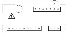
3.2 Back Panel
The back panel consists of four different connectors that can be used with removable terminal blocks (included):
|
|
|
|
|
|
|
|
19 |
18 |
17 |
16 |
15 |
14 |
13 |
|
D |
pH/ORP |
|
|
|
|
|
|
|
|
|
|
|
J3 |
C |
|
|
|
|
|
|
|
|
NC |
NC |
NC |
NC |
100 Pt |
100 Pt |
100 Pt |
||
|
|
|
|
|
|
|
|
|
|||||||
|
|
|
|
|
|
|
|
|
|
|
|
- |
- |
- |
|
|
WARNING |
|
|
|
|
|
|
|
|
|
GND |
IN |
SENSE |
|
|
|
|
|
|
|
|
|
|
|
|
|
|
|
|||
|
12 |
11 |
10 |
9 |
8 |
7 |
6 |
5 |
4 |
|
|
3 |
2 |
1 |
|
B |
J2 |
|
|
|
|
|
|
|
|
|
|
|
|
J1 |
A |
|
|
|
|
|
|
|
|
|
|
|
|
|
|
||
|
mA 20 - 4 + |
mA 20 - 4 - |
NO - 1 RELAY |
POLE - 1 RELAY |
NC - 1 RELAY |
NO - 2 RELAY |
POLE - 2 RELAY |
NC - 2 RELAY |
GND LIQUID |
|
|
GROUND |
N |
L |
|
A.3 pin connector (for power supply)
B.9 pin connector (for relays)
C.7 pin connector (for temperature sensor)
D.BNC connector (for pH or ORP electrode)
A. |
1. L- Live |
C. |
13. Pt 100SENSE |
|
2. N- Neutral |
|
14. Pt 100IN |
|
3. E- Earth Ground |
|
15. Pt 100-GND |
|
|
|
16. NC |
|
|
|
17. NC |
|
|
|
18. NC |
|
|
|
19. NC |
B. |
4. Liquid GND |
D. |
BNC for pH/ORP |
|
5. RELAY 2- NC |
|
|
|
6. RELAY 2- POLE |
|
|
|
7. RELAY 2- NO |
|
|
|
8. RELAY 1- NC |
|
|
|
9. RELAY 1- POLE |
|
|
|
10. RELAY 1- NO |
|
|
|
11. – 4 to 20 mA |
|
|
|
12. +4 to 20 mA |
|
|
- 4 -

3.3 Wiring
Caution: Ensure electrical mains is disconnected before proceeding.
1. Connect the power supply to the three-pin terminal block (D)
•VAC protective ground wire = 3
•VAC neutral wire = 2
•VAC live wire = 1
The alpha pH 200 controller accepts voltages from 85 to 260 VAC, 50/60 Hz or DC.
2.Connect the Pt 100 leads to terminals 13 and 15 (terminal block B). Either wire can be connected to either terminal. Terminals 13 and 14 must be shunted unless using a 3-wire RTD.
NOTE: pH 200 is factory set for manual temperature compensation. ATC can be selected in Program P3.3.
3.Slide the BNC connector of the pH (ORP) probe to the BNC connector on the back of the controller.
Turn the notches of the connector until they lock into place.
4.Power on the controller. The display automatically shows the pH (ORP) reading, and the pH (ORP) annunciator lights.
NOTE: In the event Pt 100 is not connected or the connection is broken in the ATC mode, the pH/ORP display flashes to alert you.
- 5 -
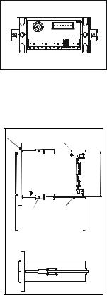
3.4 Panel-mounting the controller
The supplied mounting hardware allows surface mounting to all panels and protective enclosures. Mounting cut-out size is 91 x 45 mm.
To attach the mounting to the controller:
1.Align the catch to the side of the controller, and insert threaded rods through catch.
BACK VIEW
2.Screw the threaded-rod through the catch in a clock-wise direction. Tighten until the catch holds the controller firmly against the back of the panel or protective housing. Repeat on the other side.
Wallp |
Catch |
Threaded |
|
|
100 |
|
|
approx. |
|
Catch |
Threadedrod |
|
|
.xorppa02.451 |
|
TOP VIEW |
|
|
|
SIDE VIEW |
|
|
- 6 - |
4 MEASUREMENT MODE
Press MODE to toggle between:
•pH (or ORP) measurement mode
•Temperature measurement mode
pH (ORP) measurement mode
The controller starts up in the mode when last powered off (pH or ORP). The appropriate annunciator lights up.
NOTE: Select pH or ORP measurement mode in Setup program P3.1.
Temperature Measurement mode
Press MODE key once to view the temperature measurement. The display shows ATC (Automatic Temperature Compensation) or MTC (Manual Temperature Compensation), then the current measured temperature. The oC annunciator lights when you are measuring temperature.
See Setup program P3.3 for further instructions.
- 7 -

5 PASSWORD
To access Calibration and Setup functions, you need to enter a password code. You cannot change calibration and setup parameters unless you first enter the password.
The alpha pH 200 controller features two separate passwords:
•pH (ORP) calibration mode password = 011
•Setup program password = 022
To enter the password:
1.Press ENTER twice. The display reads “P.000”. The first “0” flashes.
2.Press ENTER again to leave the first digit “0” and to scroll to the next number.
3.Press the ▲ and ▼ keys to change the second digit to the correct number (1 or 2). Press ENTER.
4.Press the ▲ and ▼ keys to change the third digit to the correct number (1 or 2). Press ENTER. The whole display will now flash to prompt for its confirmation.
If you enter an incorrect digit, press MODE to back up.
5.Press ENTER again to confirm your password. You are now in Calibration mode or Setup mode, depending on password entered.
- 8 -
 Loading...