


Instruction Manual
αlpha CON 2000
Conductivity/ Total Dissolved Solids
Controller / Transmitter
Technology Made Easy ...
68X216843 Rev 1 01/04

Preface
This manual serves to explain the use of the αlpha CON 2000 Series. The manual functions in two ways, firstly as a step by step guide to help the user operate the instrument, and secondly as a handy reference guide. This instruction manual is written to cover as many anticipated applications of the αlpha CON 2000 as possible. If you have any doubts concerning the use of the instrument, please do not hesitate to contact the nearest Eutech Instruments Authorised Distributor.
The information presented in this manual is subject to change without notice as improvements are made, and does not represent any commitment whatsoever on the part of Eutech Instruments.
Eutech Instruments will not accept any responsibility for damage or malfunction of the unit due to improper use of the instrument.
Copyright ©2003 All rights reserved.
Eutech Instruments Pte Ltd
Rev 1 01/04

Safety Information
This Eutech Instruments Controller/ Transmitter shall be installed and operated only in the manner specified in the Instruction manual. Only skilled, trained or authorised person should carry out installation, setup and operation of the instrument.
Before powering up the unit, make sure that power source it is connected to, is as specified in the top label. Failure to do so may result in a permanent damage to the unit.
The unit has live and exposed parts inside. If it has to be opened, make sure that the power to the unit is off and disconnected.
The unit is Fuse protected. In the event the fuse has to be replaced, use only those as specified in the manual.
The degree of protection against electric shock will be achieved only by observance of the corresponding installation rules.

TABLE OF CONTENTS
1 INTRODUCTION ....................................................................................................................................... |
1 |
|
1.1 |
AT THE VERY BEGINNING...................................................................................................................... |
1 |
1.2 |
INTENDED USE ...................................................................................................................................... |
1 |
1.3 |
SAFETY INTSRUCTIONS ......................................................................................................................... |
2 |
1.4 |
PUTTING OUT OF SERVICE / CORRECT DISPOSAL OF THE UNIT ............................................................... |
2 |
2 |
PRODUCT DESCRIPTION....................................................................................................................... |
3 |
|
|
2.1 |
DESCRIPTION OF UNIT ........................................................................................................................... |
3 |
|
2.2 |
MEASUREMENT AND CONTROL SYSTEM................................................................................................ |
4 |
|
2.3 |
UNIT OVERVIEW ................................................................................................................................... |
5 |
|
2.3.1 |
Display Overview ............................................................................................................................ |
6 |
|
2.3.2 |
Key functions................................................................................................................................... |
6 |
|
2.3.3 |
LED indicators ................................................................................................................................ |
7 |
|
2.3.4 |
Security codes.................................................................................................................................. |
7 |
|
2.3.5 |
Menu overview ................................................................................................................................ |
8 |
3 |
ASSEMBLY AND INSTALLATION........................................................................................................ |
9 |
|
|
3.1 |
MOUNTING THE UNIT ............................................................................................................................ |
9 |
|
3.2 |
CONNECTION DIAGRAM...................................................................................................................... |
11 |
4 |
NORMAL OPERATION.......................................................................................................................... |
15 |
|
|
4.1 |
MEASUREMENT MODE ........................................................................................................................ |
15 |
5 |
CALIBRATION MODE........................................................................................................................... |
16 |
|
|
5.1 |
ENTERING CALIBRATION MODE .......................................................................................................... |
16 |
|
5.2 |
CALIBRATION ..................................................................................................................................... |
17 |
|
5.3 |
VIEW ACTUAL CELL CONSTANT AND CALIBRATION FACTOR ............................................................... |
18 |
6 |
SETUP MODE........................................................................................................................................... |
19 |
|
|
6.1 |
ENTER SETUP MODE............................................................................................................................ |
19 |
|
6.2 |
TEMPERATURE COMPENSATION (TC) SUB-FUNCTION ......................................................................... |
20 |
|
6.3 |
SETTING TEMPERATURE (SET °C°F) SUB-FUNCTION ........................................................................... |
21 |
|
6.4 |
CONTROL RELAY A / RELAY B (SP1/SP2) SUB-FUNCTION ................................................................. |
22 |
|
6.5 |
CONTROLLER (CNTR) SUB-FUNCTION ............................................................................................... |
24 |
|
6.6 |
CURRENT OUTPUT 1 SUB-FUNCTION ................................................................................................... |
27 |
|
6.7 |
CURRENT OUTPUT 2 SUB-FUNCTION ................................................................................................... |
28 |
|
6.8 |
WASH RELAY (WASH) SUB-FUNCTION .............................................................................................. |
29 |
|
6.9 |
MEASURING RANGE SELECTION (RANG) SUB-FUNCTION ................................................................... |
30 |
|
6.10 |
CONFIGURATION (CNFG) SUB-FUNCTION .......................................................................................... |
31 |
|
6.11 |
CALIBRATION (CAL) SUB-FUNCTION.................................................................................................. |
32 |
7 |
RELAY MODES ....................................................................................................................................... |
33 |
|
|
7.1 |
VIEW RELAY SET POINTS..................................................................................................................... |
33 |
|
7.2 |
MANUAL RELAY MODE ....................................................................................................................... |
34 |
8 |
TECHNICAL SPECIFICATIONS .......................................................................................................... |
35 |
|
|
8.1 |
GENERAL SPECIFICATIONS .................................................................................................................. |
35 |
|
8.2 |
SPECIFICATIONS FOR WALL MOUNT VERSION...................................................................................... |
36 |
|
8.3 |
SPECIFICATIONS FOR PANEL MOUNT VERSION..................................................................................... |
37 |
9 |
ACCESSORIES......................................................................................................................................... |
38 |
|
|
9.1 |
REPLACEMENT UNIT........................................................................................................................... |
38 |
|
9.2 |
ASSEMBLY ACCESSORIES ................................................................................................................... |
38 |
10 |
GENERAL INFORMATION................................................................................................................... |
39 |
|
|
10.1 |
WARRANTY ........................................................................................................................................ |
39 |
|
|
|
|

10.2 |
PACKAGING / SCOPE OF DELIVERY...................................................................................................... |
39 |
|
10.3 |
RETURN OF GOODS.............................................................................................................................. |
39 |
|
10.4 |
GUIDELINES FOR RETURNING UNIT FOR REPAIR .................................................................................. |
39 |
|
10.5 |
MAINTENANCE AND CLEANING .......................................................................................................... |
40 |
|
11 APPENDICES ........................................................................................................................................... |
41 |
||
11.1 |
APPENDIX 1 – UNIT FUSE AND JUMPER SETTINGS................................................................................ |
41 |
|
11.2 |
APPENDIX 2 – CONDUCTIVITY OF VARIOUS AQUEOUS SOLUTIONS AT 25 °C / 77 °F............................ |
43 |
|
11.3 |
APPENDIX 3 – SIMPLE EXPLANATION ON THE FUNCTION OF HYSTERESIS ............................................ |
44 |
|
11.4 |
APPENDIX 4 – GENERAL INSTRUCTIONS CONCERNING CONTROLLER SETTING ................................... |
45 |
|
11.4.1 |
Control characteristic of Controllers used as limit value switch ............................................. |
45 |
|
11.4.2 |
Control characteristic of P-Controllers as proportional controller......................................... |
45 |
|
11.4.3 |
Control characteristic of PI-Controllers as proportional integral controller.......................... |
45 |
|
11.4.4 |
Control signal of Pulse length Controllers............................................................................... |
46 |
|
11.4.5 |
Control signal of Pulse Frequency Controllers........................................................................ |
47 |
|
11.5 |
APPENDIX 5 – ABBREVIATIONS USED IN MENU DISPLAYS ................................................................... |
48 |
|
Instruction Manual |
αlpha CON 2000 |
1 INTRODUCTION
1.1At the very beginning
We thank you for having purchased the Eutech Instruments αlpha CON 2000.
The construction of the αlpha CON 2000 employs leading edge technology and complies with safety regulations currently in force. Notwithstanding this, improper use could lead to hazards for the user or a third-party, and/or adverse effects on the plant or other equipment. Therefore, the operating instructions must be read and understood by the persons involved before work is started with the αlpha CON 2000.
Eutech Instruments do not accept any liability for damage that may arise from neglecting information given in this manual.
This instruction manual identifies safety instructions and additional information by means of the following symbols:
This symbol draws attention to safety instructions and warnings of potential danger which, if neglected, could result in injury to persons and/or damage to property.
This symbol identifies additional information and instructions which, if neglected, could lead to inefficient operation and possible loss of production.
The instruction manual must always be stored close at hand, in a place accessible to all people working with the αlpha CON 2000 .
If you have questions, which are not or insufficiently answered in this instruction manual, please contact your Eutech Instruments supplier. He will be glad to assist you.
1.2Intended use
Eutech Instruments αlpha CON 2000 is intended solely for conductivity and temperature measurement, as described in this instruction manual.
Any other use, or use not mentioned here, that is incompatible with the technical specifications is deemed inappropriate. The operator is solely responsible for any damage arising from such use.
Other prerequisites for appropriate use include:
−observing the instructions, notes and requirements set out in this instruction manual.
−observing all local safety regulations concerning safety at work.
−observing all information and warnings in the documentation dealing with the products used together with the transmitter (housings, sensors, etc.).
−observing the prescribed environmental and operational conditions.
1

Instruction Manual |
αlpha CON 2000 |
1.3Safety intsructions
The αlpha CON 2000 should be installed and operated only by personnel familiar with the transmitter and who are qualified for such work.
A defective transmitter must neither be installed nor put into service.
The αlpha CON 2000 must only be operated under the specified operating conditions (see section 8).
The αlpha CON 2000 must not be repaired by the customer.
The αlpha CON 2000 must only be opened to replace the unit fuse or to set the jumper for Pt100/Pt1000 temperature sensor. This work must be carried out only by personnel familiar with the transmitter and who are qualified for such work. Make sure the mains cable is separated from the power supply before opening the unit.
No modifications to the αlpha CON 2000 are allowed. The manufacturer/supplier accepts no responsibility for damage caused by unauthorised modifications. The risk is borne entirely by the user.
1.4Putting out of service / Correct disposal of the unit
Putting out of service
•First disconnect the unit from the mains, then undo all electrical connections.
•Remove the unit from the wall / panel.
Correct disposal of the unit
When the transmitter is finally taken out of service, observe the local environmental regulations for correct disposal or send the transmitter to your local Eutech Instruments distributor, they will take care of proper disposal.
2

Instruction Manual |
αlpha CON 2000 |
2 PRODUCT DESCRIPTION
2.1Description of unit
The Eutech Instruments αlpha CON 2000 is used for measuring conductivity and temperature values. The conductivity values can be measured using limit or P/PI control. The transmitter is available in two versions, one for panel mounting and one for wall mounting in a enclosure. The transmitter can be used for applications such as water treatment and monitoring, galvanic-decontamination, chemical processing, food processing, clean or wastewater control and neutralisation processes.
This transmitter has many user-friendly and safety features which include:
•Menu-driven program that simplifies set-up.
•Built-in non-volatile memory to ensure that calibration and other information are not erased if power supply fails.
•Push-button for calibration and sensor offset adjustment from the keypad.
•Automatic temperature compensation (ATC).
•Manual temperature compensation setting without the ATC probe, with independent setting for calibration and process temperature.
•Two galvanically isolated current outputs 0/4...20mA.
•0 to 2000 seconds time delay adjustment on all relays – minimises false alarms.
•Separately adjustable high and low set-point hysteresis (dead bands) prevent chattering of relays around the set points.
•Three control modes: limit controller, P controller and PI controller (P/PI controller as pulse length or pulse frequency).
•Large dual display LCD for easy reading with clear multiple annunciators, alarm status, operational and error messages.
•Two switching contacts as set-point relays.
•Separate alarm relay alerting you to set point limits exceeded for a certain time and if the Pt100/Pt1000 wires are broken or disconnected during the ATC function.
•Wash relay.
•Hold function to freeze output current (0/4...20mA) and release control relays.
•LED indicators signal control activities to visually monitor transmitter status from a distance.
•Protection against electromagnetic interference. ( Available for panel mount only)
•Back lit and UV light protected LC display.
3
Instruction Manual |
αlpha CON 2000 |
2.2Measurement and control system
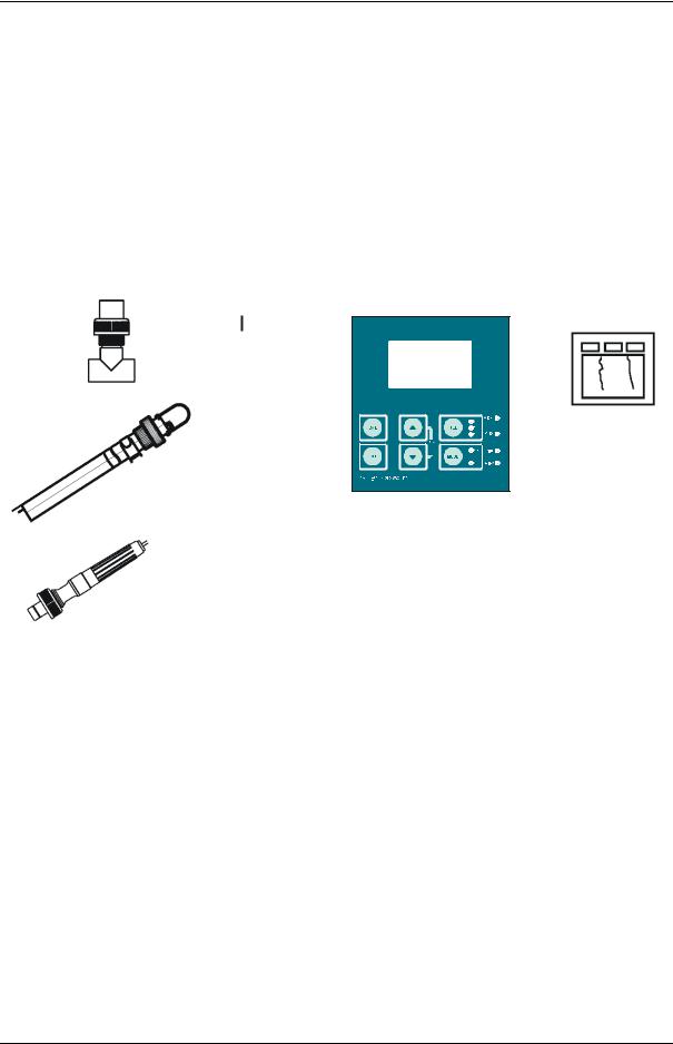
A typical measurement system consists of:
•A conductivity process transmitter
•A conductivity sensor with integrated or separate temperature sensor Pt100/Pt1000.
•An appropriate measurement cable
•An immersion, flow or process assembly
•A final control element such as pump or valve
•A chart recorder
Alpha CON 2000 Transmitter
Chart Recorder
|
|
|
|
|
|
|
|
|
|
0/4 - 20 mA |
|
|
|
|
|
|
|
|
|
|
|
|
|
||
|
|
|
|
|
|
|
|
|
|
|
||
|
|
|
|
|
|
|
|
|
|
|
||
|
|
|
|
|
|
|
|
|
|
|
||
|
|
|
|
|
|
|
|
|
|
|
||
|
|
|
|
|
|
|
|
|
|
|
||
|
|
|
|
|
|
|
|
|
|
|
||
|
|
|
|
|
|
|
|
|
|
|
||
|
|
|
|
|
|
|
|
|
|
|
||
|
|
|
|
|
|
|
|
|
|
|
||
|
|
|
|
|
|
|
|
|
|
|
||
|
|
|
|
|
|
|
|
|
|
|
||
|
|
|
|
|
|
|
|
|
|
|
||
|
|
|
|
|
|
|
|
|
|
|
||
|
|
|
|
|
|
|
|
|
|
|
||
|
|
|
|
|
|
|
|
|
|
|
||
|
|
|
|
|
|
|
|
|
|
|
||
|
|
|
|
|
|
|
|
|
|
|
||
|
|
|
|
|
|
|
|
|
|
|
|
|
|
|
|
|
|
|
|
|
|
|
|
Power Mains |
|
|
|
|
|
|
|
|
|
|
|
|
||
|
|
|
|
|
|
|
|
|
|
|
||
Housing and |
Measurement Cable |
|
(80 - 250 VAC) |
|||||||||
|
|
|
|
|
|
|
|
|||||
Sensors
4
Instruction Manual |
αlpha CON 2000 |
2.3Unit overview
Wall mounting version
Panel mounting version
5
Instruction Manual |
αlpha CON 2000 |
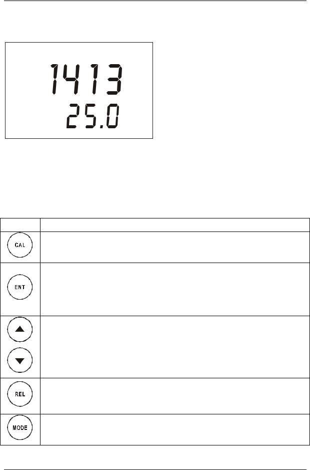
2.3.1Display Overview
The LC display shows two alpha-numerical fields for parameters and measured values as well as various mode and status indicators.
SETUP MEAS CAL
HOLD |
mS |
|
µS |
ERR
°C °F
4 |
ATC |
2.3.2Key functions
Mode indicators:
MEAS: measurement mode SETUP: Set-up mode CAL: Calibration mode
Status indicator:
HOLD: Unit in “HOLD” mode
ATC: Visible in ATC (Automatic Temperature Compensation) mode. Not visible in the Manual Temperature Compensation mode. “ATC” flashes if the temperature probe is faulty in its ATC mode
ERR: Error indicator
4: Measurement range number
Key Description
Enter Calibration mode (requires access code)
Enter Set-up mode (requires access code)
Access sub functions (parameters) within a function group of Set-up mode
Confirm (store) set-up parameters and numerical values
Start/Confirm calibration in Calibration mode.
Select function group in the Set-up mode.
Set parameters and numerical values (if key is pressed continuously, the setting speed increases).
Control the relays in MANUAL relay operation.
Returns to “Measurement mode” when both keys are pressed simultaneously.
Display limit values for SP1 and SP2 and settings for wash contact in AUTO relay operation.
Toggle between RELAY A, RELAY B or Wash relay in MANUAL relay operation
Switch from AUTO to MANUAL relay operation (requires access code)
6
Instruction Manual |
αlpha CON 2000 |
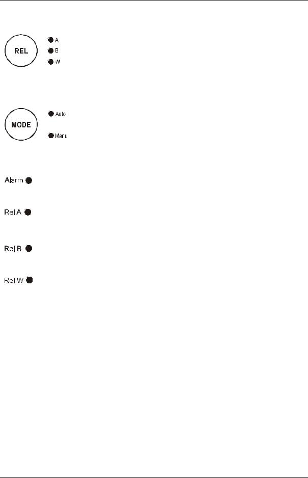
2.3.3 LED indicators
Relay indicators
If REL key is pressed the LED (A, B or W) indicates to which Relay (A, B or
Wash) the displayed limit values refer.
Relay mode indicators
Auto LED lights if relay operation is set to automatic mode. Manu LED lights if relay operation is set to manual mode.
Relay status indicators
This LED lights if limit value is exceeded or the ATC probe fails.
This LED lights green if measured value is within the limit for Relay A or lights red if measured value exceeds limit.
This LED lights green if measured value is within the limit for Relay B or lights red if measured value exceeds limit.
This LED lights if cleaning cycle is on.
2.3.4Security codes
The access to Calibration mode, Setup mode and Manual relay operation mode is protected with security codes. The security codes are set at the factory and cannot be changed by the user. The following security codes are used:
Security code Mode |
Description |
|
|
000 |
View only mode to view actual settings |
|
|
11 |
Calibration mode to start calibration |
|
|
22 |
Setup mode to configure parameters |
|
|
22 |
Manual relay operation to switch relay operation mode from |
|
automatic to manual |
7

Instruction Manual |
αlpha CON 2000 |
2.3.5Menu overview
|
MEAS |
|
µS |
|
°C |
|
4 |
CAL |
ENTER |
1 |
2 |
ENTER |
ENTER |
1CCD “000” = Check calibration parameters (View only mode) CCD “11” = Calibration mode
2SCD “000” = Check setup parameters (View only mode) SCD “22” = Setup mode
SETUP
HOLD
4
SETUP
HOLD
4
SETUP
HOLD
4
SETUP
HOLD
4
SETUP
HOLD
4
SETUP
HOLD
4
SETUP
HOLD
4
SETUP
HOLD
4
SETUP
HOLD
4
SETUP
HOLD
4
SETUP
HOLD
 4
4
ENT
ENT
ENT
ENT
ENT
ENT
ENT
ENT
ENT
ENT
ENT
CAL
Temperature settings see section 6.3
Relay A (set point 1) settings see section 6.4
Relay B (set point 2) settings see section 6.4
Controller settings see section 6.5
Current output 1 settings see section 6.6
Current output 2 settings see section 6.7
Wash contact settings see section 6.8
Range settings see section 6.9
Unit settings see section 6.10
Calibration see section 5
8
Instruction Manual |
αlpha CON 2000 |
3 ASSEMBLY AND INSTALLATION
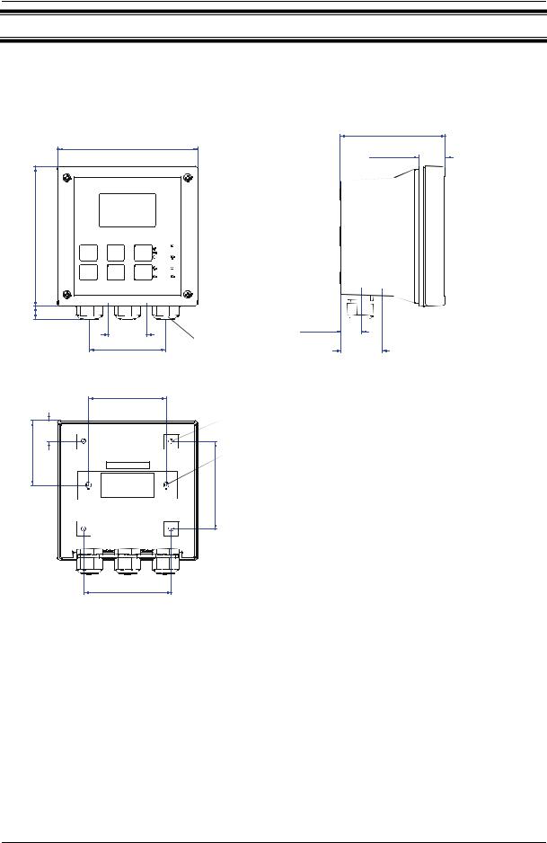
3.1Mounting the unit
Wall mounting version
111.50 [4.39]
144 [5.67]
27.5 [1.08]
144 [5.67]
14 [.55] |
|
Pg13.5 (3 pcs.) |
|
approx. |
|
For Pg13.5 cable glands |
|
|
39 [1.54] |
24 [.94] |
|
|
78 [3.07] |
|
57.8[2.28] |
80 [3.15]
[2.62] |
21.5 [.85] |
66.5 |
|
6 [.24]
Holes for post mounting (4X)
Holes for wall mounting (2X)
90 [3.54]
Unit:
MM [INCH]
90 [3.54]
Transmitter housing for wall mounting: protection class IP 65
9
Instruction Manual |
αlpha CON 2000 |
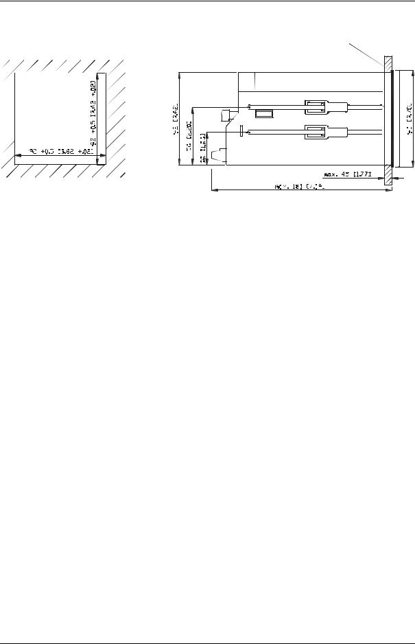
Panel mounting version
Flat gasket 1mm [.04]
(to be inserted by customer)
Panel cut out
UNIT: MM [INCH]
Transmitter housing for panel mounting: protection class IP 54 (front), IP 40 (housing)
10
Instruction Manual |
αlpha CON 2000 |
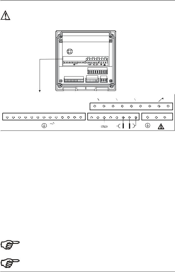
3.2Connection Diagram
Caution: Ensure electrical mains are disconnected before proceeding.
Connections for wall mounting version
|
|
|
|
|
|
|
|
|
R ELA |
|
|
R ELB |
|
WASH R ELAY |
A LAR M R ELAY |
|||
|
|
|
|
|
|
|
|
4 |
|
5 |
6 |
|
7 |
8 |
9 |
12 |
11 |
10 |
29 |
28 |
31 |
30 |
20 |
19 |
22 |
14 |
13 |
24 |
25 |
26 |
15 |
16 |
17 |
18 |
3 |
2 |
1 |
+- + -
Current |
Current GND+12V |
HOLD |
PT100/ |
N |
L |
OP 2 |
OP1 |
|
PT1000 |
|
|
|
|
|
|
|
|
|
|
|
|
|
|
|
|
|
|
|
|
|
|
|
RELA |
|
|
RELB |
|
|
WASH RELAY |
|
|
ALARM RELAY |
|||||||||||||||||||
|
|
|
|
|
|
|
|
|
|
|
|
|
|
|
|
|
|
|
|
|
|
|
|
|
|
|
|
|
|
|
|
|
|
|
|
|
|
|
|
|
|
|
|
|
|
|
|
|
|
|
|
|
|
|
|
|
|
|
|
|
|
|
|
|
|
|
|
|
|
|
|
|
|
|
|
|
|
|
|
|
|
|
|
|
|
|
|
|
|
|
|
|
|
|
|
|
|
|
|
|
|
|
|
|
|
|
|
|
|
|
|
|
|
|
|
|
|
|
4 |
|
|
|
5 |
|
6 |
|
|
|
|
7 |
8 |
9 |
12 |
11 |
10 |
||||||||||||||
|
29 |
28 |
31 |
30 |
20 |
19 |
22 |
14 |
13 |
|
|
24 |
|
25 |
26 |
15 |
|
16 |
17 |
|
18 |
|
3 |
|
2 |
|
1 |
|
|||||||||||||||||||||
|
+ |
|
- |
|
+ |
|
- |
|
|
|
|
|
|
|
|
|
|
|
PT100/ |
|
|
|
|
|
|
|
|
|
|
|
|
|
|
|
|
|
|
|
|
|
|
|
|
|
|
|
|
|
|
|
Current |
Current GND+12V |
|
|
HOLD |
|
|
|
|
|
|
|
|
|
|
|
|
|
|
|
|
|
|
|
|
|
|
|
N |
|
L |
||||||||||||||||||
|
OP 2 |
OP1 |
|
|
|
|
|
|
|
|
|
|
PT1000 |
|
|
|
|
|
|
|
|
|
|
|
|
|
|
|
|
|
|
|
|
|
|
|
|
|
|
|
|
||||||||
|
|
|
|
|
|
|
|
|
|
|
|
|
|
|
|
|
|
|
|
|
|
|
|
|
|
|
|
|
|
|
|
|
|
|
|
|
|
|
|
|
|
|
|
|
|
|
|
|
|
1. |
|
|
|
AC mains live wire |
|
|
|
|
**17. |
|
|
4 Cell / 2 Cell type Conductivity Input |
|
|
|
||||||||||||||||||||||||||||||||||
2. |
|
|
|
AC mains neutral wire |
|
|
18. |
|
|
4 Cell type Conductivity Input |
|
|
|
|
|
|
|||||||||||||||||||||||||||||||||
3. |
|
|
|
AC mains protective earth wire |
19. |
|
|
12V Power supply |
|
|
|
|
|
|
|
|
|
|
|
|
|
||||||||||||||||||||||||||||
4. |
|
|
|
Relay A (SP 1) |
|
|
|
|
|
|
20. |
|
|
12V ground |
|
|
|
|
|
|
|
|
|
|
|
|
|
|
|
|
|
||||||||||||||||||
5. |
|
|
|
Relay A (SP 1) |
|
|
|
|
|
|
21. |
|
|
no connection |
|
|
|
|
|
|
|
|
|
|
|
|
|
|
|
||||||||||||||||||||
6. |
|
|
|
Relay B (SP 2) |
|
|
|
|
|
|
22. |
|
|
Earth ground |
|
|
|
|
|
|
|
|
|
|
|
|
|
|
|
|
|
||||||||||||||||||
7. |
|
|
|
Relay B (SP 2) |
|
|
|
|
|
|
23. |
|
|
no connection |
|
|
|
|
|
|
|
|
|
|
|
|
|
|
|
||||||||||||||||||||
8. |
|
|
|
Wash relay |
|
|
|
|
|
|
|
|
24. |
|
|
Temperature ground |
|
|
|
|
|
|
|
|
|
|
|
|
|
||||||||||||||||||||
9. |
|
|
|
Wash relay |
|
|
|
|
|
|
|
|
25. |
|
|
Temperature input |
|
|
|
|
|
|
|
|
|
|
|
|
|
||||||||||||||||||||
10. |
|
|
Alarm relay (NC) |
|
|
|
|
26. |
|
|
Temperature sense (short to |
|
|
|
|
|
|
|
|
|
|||||||||||||||||||||||||||||
11. |
|
|
Alarm relay common |
|
|
|
|
|
terminal 25 if using 2- wire RTD) |
|
|
|
|
|
|
||||||||||||||||||||||||||||||||||
12. |
|
|
Alarm relay (NO) |
|
|
|
|
27. |
|
|
no connection |
|
|
|
|
|
|
|
|
|
|
|
|
|
|
|
|||||||||||||||||||||||
13. |
|
|
Hold function |
|
|
|
|
|
|
28. |
|
|
4-20 mA temperature output, -ve terminal |
||||||||||||||||||||||||||||||||||||
14. |
|
|
Hold function |
|
|
|
|
|
|
29. |
|
|
4-20 mA temperature output, +ve terminal |
||||||||||||||||||||||||||||||||||||
15. |
|
|
4 Cell type Conductivity Input |
30. |
|
|
4-20 mA Conductivity output, -ve terminal |
||||||||||||||||||||||||||||||||||||||||||
**16. |
|
|
4 Cell / 2 Cell type Conductivity Input |
31. |
|
|
4-20 mA Conductivity output, +ve terminal |
||||||||||||||||||||||||||||||||||||||||||
IMPORTANT: The Alarm relay functions as an “Active Low” device i.e. it switches OFF under Alarm condition. Therefore the Alarm display device should be connected to the ‘NC’ contacts of the relay (10 & 11).
** When using 2 Cell type Conductivity electrode, terminal 15 should be shorted to terminal 16 and terminal 18 should be shorted to terminal 17.
11
 Loading...