


 Loading...
Alpha COND 500
Controller/Transmitter uS / mS / ºC
ROSS and the COIL trade dress are trademarks of Thermo Fisher Scientific Inc. U.S. patent 6,793,787.
AQUAfast, Cahn, ionplus, KNIpHE, No Cal, ORION, perpHect, PerpHecT, PerpHecTion, pHISA, pHuture, Pure Water, Sage, Sensing the Future, SensorLink, ROSS, ROSS Ultra, Sure-Flow, Titrator PLUS and TURBO2 are registered trademarks of Thermo Fisher.
1-888-pHAX-ION, A+, All in One, Aplus, AQUAsnap, AssuredAccuracy, AUTOBAR, AUTO-CAL, AUTO DISPENSER, Auto-ID, AUTO-LOG, AUTO-READ, AUTOSTIR, Auto-Test, BOD AutoEZ, Cable-Free, CERTI-CAL, CISA, DataCOLLECT, DataPLUS, digital LogR, DirectCal, DuraProbe, Environmental Product Authority, Extra Easy/Extra Value, FAST QC, GAP, GLPcal, GLPcheck, GLPdoc, ISEasy, KAP, LabConnect, LogR, Low Maintenance Triode, Minimum Stir Requirement, MSR, NISS, One-Touch, One-Touch Calibration, One-Touch Measurement, Optimum Results, Orion Star, Pentrode, pHuture MMS, pHuture Pentrode, pHuture Quatrode, pHuture Triode, Quatrode, QuiKcheK, rf link, ROSS Resolution, SAOB, SMART AVERAGING, Smart CheK, SMART STABILITY, Stacked, Star Navigator 21, Stat Face, The Enhanced Lab, ThermaSense, Triode, TRIUMpH, Unbreakable pH, Universal Access are trademarks of Thermo Fisher.
Guaranteed Success and The Technical Edge are service marks of Thermo Fisher.
PerpHecT meters are protected by U.S. patent 6,168,707. PerpHecT ROSS electrodes are protected by U.S. patent 6,168,707. ORION Series A meters and 900A printer are protected by U.S. patents 5,198,093, D334,208 and D346,753.ionplus electrodes and Optimum Results solutions are protected by U.S. patent 5,830,338.ROSS Ultra electrodes are protected by U.S. patent 6,793,787.ORP standard is protected by U.S. patent 6,350,367. No Cal electrodes are protected by U.S. patent 7,276,142.© 2009 Thermo Fisher Scientific Inc. All rights reserved. All trademarks are the property of Thermo Fisher Scientific Inc. and its subsidiaries.The specifications, descriptions, drawings, ordering information and part numbers within this document are subject to change without notice.This publication supersedes all previous publications on this subject.
Preface
This manual serves to explain the use of the Alpha COND 500 transmitter. It functions in two ways, firstly as a step by step guide to help you to operate the transmitter. Secondly, it serves as a handy reference guide. It is written to cover as many anticipated applications of the transmitter as possible. If there are doubts in the use of the transmitter, please do not hesitate to contact the nearest Authorized Distributor.
Thermo Scientific will not accept any responsibility for damage or malfunction to the transmitter caused by improper use of the instrument.
The information presented in this manual is subject to change without notice as improvements are made, and does not represent a commitment on the part of Thermo Scientific.
Copyright © 2009
All rights reserved
TABLE OF CONTENTS |
|
||
1 |
INTRODUCTION ................................................................................... |
1 |
|
2 |
PREPARATION .................................................................................... |
2 |
|
2.1 |
POWER SUPPLY REQUIREMENTS (SL2 POSITION)........................................... |
3 |
|
2.2 |
CONNECTING THE ELECTRODE AND TEMPERATURE SENSOR (SL1 POSITION).... |
3 |
|
3 |
INSTALLATION .................................................................................... |
5 |
|
3.1 |
MECHANICAL DIMENSIONS ............................................................................ |
5 |
|
3.2 |
WALL MOUNT.............................................................................................. |
5 |
|
3.3 |
PANEL MOUNT ............................................................................................ |
6 |
|
4 |
DISPLAY AND KEYPAD FUNCTIONS ................................................ |
7 |
|
4.1 |
DISPLAY ..................................................................................................... |
7 |
|
4.2 |
KEYPAD ...................................................................................................... |
8 |
|
5 |
CALIBRATION...................................................................................... |
9 |
|
5.1 |
IMPORTANT INFORMATION ON TRANSMITTER CALIBRATION ............................... |
9 |
|
5.2 |
TEMPERATURE CALIBRATION ...................................................................... |
11 |
|
5.3 |
CONDUCTIVITY CALIBRATION ...................................................................... |
12 |
|
6 |
ADVANCED SETUP FUNCTIONS ..................................................... |
13 |
|
6.1 |
RANGE AND ZOOMING SELECTION SETTING.................................................. |
13 |
|
6.2 |
TEMPERATURE COMPENSATION SETTING ..................................................... |
15 |
|
6.3 |
HOLD CURRENT SETTING.......................................................................... |
18 |
|
6.4 |
OUT-OF-RANGE CURRENT SETTING ............................................................ |
18 |
|
6.5 |
TEMPERATURE COEFFICIENT AND NORMALIZATION TEMPERATURE SETTING .... |
19 |
|
6.6 |
CELL CONSTANT SETTING .......................................................................... |
20 |
|
6.7 |
LINE RESISTANCE SETTING ......................................................................... |
20 |
|
6.8 |
VIEWING CALIBRATION POINT...................................................................... |
21 |
|
6.9 |
VIEWING THE ELECTRODE DATA.................................................................. |
21 |
|
6.10 |
RESET FUNCTION ...................................................................................... |
22 |
|
7 |
FACTORY DEFAULT SETTINGS ...................................................... |
23 |
|
8 |
TROUBLE SHOOTING GUIDE........................................................... |
24 |
|
9 |
SPECIFICATIONS .............................................................................. |
25 |
|
10 |
ACCESSORIES .................................................................................. |
26 |
|
11 |
WARRANTY........................................................................................ |
27 |
|
12 |
RETURN OF ITEMS............................................................................ |
27 |
|
1 INTRODUCTION
Thank you for selecting an Alpha COND 500 2-Wire Transmitter. This isolated output 4-20mA transmitter is a sturdy microprocessor-based instrument that measures conductivity and temperature and transmits its output via the 2-wire power supply loop.
This transmitter has many user-friendly features – all of which are completely accessible through the water-resistant membrane keypad. Your transmitter includes an instruction manual and a warranty card.
Please read this manual thoroughly before operating your transmitter.
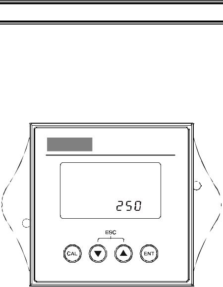
|
Alpha COND 500 |
|
|
MEAS |
|
READY |
1413μS |
|
|
. |
°C |
|
ATC |
|
2-wire Conductivity Transmitter |
||
2 PREPARATION
Remove screws from the four corners at the back of the Transmitter, and remove back cover.
Connectors should be exposed as follows:
 NC
NC
NC
 NC
NC
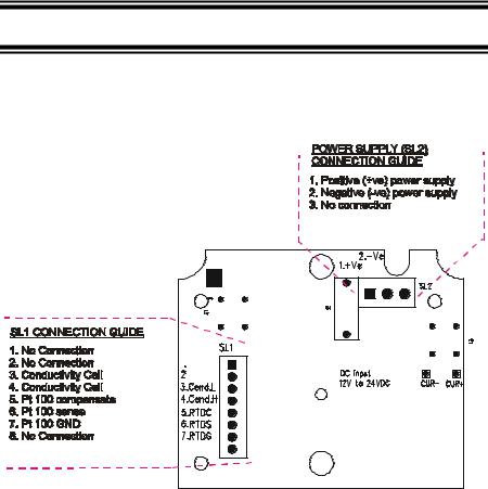
Figure 1 – Connection Guide
All wiring is done on 2 detachable connectors: –
1.9-pin connector (located on SL1 position) for Conductivity electrode and temperature sensor; &
2.3-pin connector (located on SL2 position) for power supply.
Using a suitable screwdriver, loosen screws from top of connector.
When inserting the wires, always hold connector with top screws facing up.

2.1Power Supply Requirements (SL2 Position)
The Alpha COND 500 transmitter requires a 12 to 24V DC power supply. Other Transmitters and/or a chart recorder may be connected in the loop.
1.Insert positive loop wire from power supply to pin 1, tighten screw.
2.Insert negative loop wire to pin 2, tighten screw. This wire may be linked to a chart recorder or to negative terminal of power supply.
1 |
|
|
|
|
|
|
|
|
|
|
|
Alpha |
|
|
|
|
Power |
COND 500 |
|
|
|
|
Supply |
2 |
|
|
|
|
|
|
|
|
|
|
|
|
|
|
|
|
|
|
|
|
|
|
Chart |
|
|
|
|
|
|
|
|
|
|
|
Recorder |
|
|
|
|
|
|
|
|
|
|
|
|
2.2Connecting the Electrode and Temperature Sensor (SL1 Position)
2.2.1To connect the Conductivity electrode:
The Alpha COND 500 transmitter accepts any industrial electrodes for conductivity measurements and they are usually offered with bare wires.
1.Insert the electrode’s conductivity wire Low into pin 3 of SL1 connector. Tighten the screw.
2.Insert the electrode’s conductivity wire High into pin 4 of SL1 connector. Tighten the screw.
 Pt 100 Input wire
 Pt 100 Sense wire

 Pt 100 Return wire
Conductivity wire High
Conductivity wire Low
Shield wire
To Electrode
2.2.2To connect ATC temperature sensor:
For Automatic Temperature Compensated (ATC) Conductivity readings, an in-built temperature sensor is usually integrated in the industrial conductivity electrodes. Otherwise, a separate 100Ω Pt RTD temperature probe can be used.
3 wire temperature sensor
1.Insert the Pt100 input wire to pin 5 of SL1 connector. Tighten the screw.
2.Insert the Pt100 sense wire to pin 6 of SL1 connector. Tighten the screw.
3.Insert the Pt100 return wire and the shield wire to pin 7 of SL1 connector. Tighten the screw.
2 wire temperature sensor
1.Take a small length of wire and short pins 5 and 6 of SL1 connector. Insert Pt 100 sense wire into pin 6 of SL1 connector and tighten the screws.
2.Insert Pt 100 return wire and the shield wire to pin 7 of SL1 connector. Tighten the screw.
IMPORTANT: It is necessary to connect the SHIELD wire to the pin 7 as stated above to eliminate possible oscillation of the conductivity and/or temperature reading due to electrical noise or interference.
Ensure that no bare wires are exposed and all screws are tightened for proper contact.

3 INSTALLATION
3.1Mechanical Dimensions
Alpha COND 500 |
2-wire Conductivity Transmitter |
3.2Wall Mount
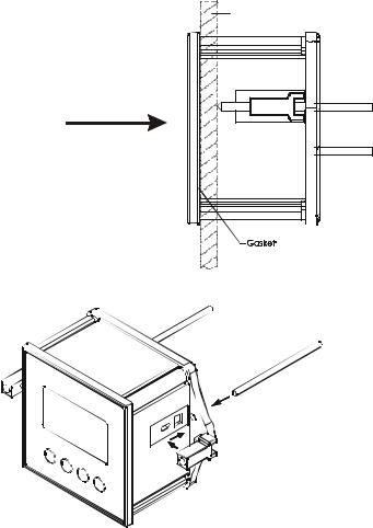
3.3 Panel Mount
1. Prepare panel cut-out of |
Panel (side) |
92.0 mm by 92.0 mm |
2. Remove back cover of transmitter and slide it through panel cut-out
4. Thread rods through lugs until transmitter is held in place against panel
3. Attach lugs to either side of transmitter
Loading...