


VP35
SUCTION UNIT
manual Service
110061 |
S-SM02e |

|
Read these Instructions before use |
|
Introduction |
Keep these ‘Instructions’ in a safe convenient place for future reference. Read in |
|
|
||
Safety notes |
conjunction with the Publications detailed in Section 1.1. |
|
Suction accessories |
Eschmann After Sales Service Department |
|
The Eschmann After Sales Service Department is staffed and equipped to provide advice and |
||
General care |
||
assistance during normal office hours. To avoid delays when making enquires, please quote the |
||
|
Model and Serial Number of your Suction Unit which is shown on the Serial Number plate, the |
|
Maintenance |
location of which is shown below. Please ensure you include all alpha and numeric digits of the |
|
|
Serial Number. |
Parts list
Technical data
Serial Number Plate
For further information visit www.eschmann.co.uk
Service manual
All correspondence relating to the after sales service of Eschmann Equipment to be addressed to :
UK Customers
Eschmann Equipment, Peter Road, Lancing, West Sussex BN15 8TJ, England. Tel: +44 (0) 1903 765040. Fax: +44 (0) 1903 762006.
Overseas Customers
Contact your local distributor. In case of doubt contact Eschmann Equipment.
Patents and Trade marks
The ESCHMANN name and logo are registered trade marks of Eschmann Holdings Limited. “Eschmann Equipment” is a trading name ofEschmann Holdings Limited.
“VP35” is trade mark of Eschmann Holdings Limited.
Patents : Patents Pending. (Application number 0124126.4)
Copyright © 2003
All rights reserved. This booklet is protected by copyright. No part of it may be reproduced, stored in a retrieval system or transmitted in any form or by any means, electronic, mechanical, photocopying, recording or otherwise without written permission from Eschmann Holdings Limited.
The information in this publication was correct at the time of going to print. The Company, however, reserves the right to modify or improve the equipment referred to.
NOTE: |
This Service Manual applies to Suction Units: |
|
REF 82-201-66 |
2-Jar with Eschmann disposable suction liner system, 230V |
|
REF 82-201-66-9999 2-Jar, with Eschmann suction jars, 230V |
||
REF 82-201-31 |
2-Jar (traditional pattern), 230V |
|
REF 82-201-80 |
Unit only with Receptal brackets, 230V |
|
REF 82-201-74 |
2-Jar with Eschmann disposable suction liner system, 110V |
|
REF 82-201-58 |
2-Jar (traditional pattern), 110V |
|
with Serial Number V3? B 0 C 0000 or later for traditional pattern jars, or with Serial Number V3? C 0 C 0000 or later for Eschmann disposable suction liner system, where ‘?’ indicates the model variant.
If the CE mark is affixed to the product, it indicates compliance with Council Directive 93/42/EEC of 14 June 1993 concerning medical devices.
S-SM02e August 2003

VP35 Suction Unit - Service Manual
READ THIS SERVICE MANUAL BEFORE USE
Keep this Service Manual in a safe convenient place for future reference during cleaning and maintenance procedures.
|
|
CONTENTS |
|
|
SECTION |
|
|
PAGE |
|
1. |
INTRODUCTION ..................................................................... |
|
4 |
|
|
General ........................................................................... |
|
4 |
|
|
Pump and Motor ............................................................. |
|
4 |
|
2. |
SAFETY NOTES ..................................................................... |
|
5 |
|
3. |
SUCTION ACCESSORIES ..................................................... |
|
5 |
|
4. |
GENERAL CARE .................................................................... |
|
6 |
|
|
Cleaning ......................................................................... |
|
6 |
|
|
Sterilisation ..................................................................... |
|
6 |
|
|
Suction unit disinfection .................................................. |
|
6 |
|
|
Daily checks ................................................................... |
|
6 |
|
5. |
MAINTENANCE ...................................................................... |
|
7 |
|
|
General ........................................................................... |
|
7 |
|
|
Checking suction performance ....................................... |
|
7 |
|
|
Checking pump oil .......................................................... |
|
7 |
|
|
Pump blade replacement and pump cleaning ................ |
|
8 |
|
|
Exhaust filter/silencer replacement ................................. |
|
8 |
|
|
Fault diagnosis ............................................................... |
|
10 |
|
6. |
PARTS LIST |
........................................................................... |
|
11 |
|
Pump/Motor unit ............................................................. |
|
11 |
|
|
Suction unit ..................................................................... |
|
12 |
|
7. |
TECHNICAL DATA .................................................................. |
|
14 |
|
APPENDIX A |
For units with traditional jar assemblies ............. |
|
15 |
|
APPENDIX B |
For units with Eschmann Suction Jars ............... |
|
16 |
|
FIGURES Fig.1 VP35 Mobile suction unit ........................................ |
|
4 |
||
|
Fig.2 Pump motor assembly ........................................... |
|
7 |
|
|
Fig.3 Pump and motor exploded view ............................. |
|
9 |
|
|
Fig.4 Pump rotor blade replacement ............................... |
|
9 |
|
|
Fig.5 VP35 Circuit diagram ............................................. |
|
9 |
|
|
Fig.6 Oil lubricated vacuum pump - spares items ........... |
|
11 |
|
|
Fig.7 VP35 Suction unit - identification for parts list ........ |
12 |
||
|
Fig.8 Traditional jar and jar top assembly ....................... |
|
15 |
|
S-SM02e |
Page 3 of 16 |
Section 1 |
VP 35 Suction Unit - Service Manual |
1. INTRODUCTION
GENERAL
1.1The VP35 is a high vacuum, high flow suction unit designed to conform with British and International Standards EN 60601-1:1990+A1:1993+A2:1995, ISO 10079-1:1991,
BS 5724:Part 1:1979, IEC 601-1:1977, IEC 601-1-2:1993.
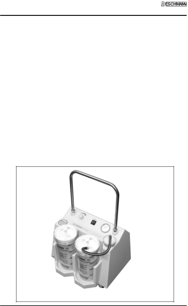
1.2The suction unit can be supplied in three ways; either with a reusable jar and disposable liner system as illustrated below in Fig. 1, or with Traditional Jars (see appendix
A), or with Eschmann Suction Jars (see Appendix B), or without jars and liners but incorporating brackets to receive ‘Abbott Receptal’ style disposable items.
PUMP AND MOTOR
1.3The vacuum pump is an oil lubricated electrically driven pump/motor unit of the rotary vane type, with replaceable blades. The motor unit is designed to operate from the mains electrical supply (see serial plate for unit voltage).
1.4The pump/motor unit, its associated pipework and electrical connections are all contained within a durable, hygienic plastic case. Controls are mounted on the top of the case and comprise an illuminated* on/off power switch, a vacuum control valve and gauge.
(* On later units the switch is not illuminated.)
1.5A silencer unit in the pump exhaust line ensures that the pump operates with the minimum of noise, while the pump inlet is protected by an externally mounted sealed bacterial or combined hydrophobic/bacterial filter, both of which are disposable.
1.6All the information necessary to maintain the VP35 portable suction unit in a serviceable condition will be found in this Service Manual.
Fig. 1 VP35 Mobile suction unit
Page 4 of 16 |
S-SM02e |
VP35 Suction Unit - Service Manual |
Section 2 & 3 |
2. SAFETY NOTES
When servicing or maintaining the ESCHMANN VP35 SUCTION UNIT, attention to the following points will prolong the life of the unit.
DO cleananddisinfectallsuctionequipment |
DON’T |
start unit without removing the |
and the unit thoroughly after use. |
|
transit bolt and washer. |
DO change the disposable filter after each |
DON’T |
use substitute accessories (see |
day’s use, or, IMMEDIATELY if wetted, |
|
available parts list). |
or, after aspiration of infective fluids. |
DON’T |
continue to use unit, without |
|
||
DO unplug and/or isolate power lead before |
|
attention, if vacuum or suction rate |
cleaningsuctionunitandwhennotinuse. |
|
is low. |
DO treat receiver jars carefully, avoiding |
DON’T |
usethe mains leador suctiontubing |
mechanical or thermal shock. |
|
as a tow rope, use the unit’s handle. |
DO examine condition of jars, lids (including |
DON’T |
use phenols or solvent based |
float function) and suction tubing |
|
disinfectants to clean receiver jar, |
regularly, replace if worn or damaged. |
|
use Savlon, Hibitane or similar |
DO keep ‘sharps’ away from liners. |
|
(also see sections 4.1 - 4.3). |
|
|
WARNING
The maintenance procedures described in this User Handbook should be made the responsibility of the engineer in charge of services in the hospital. If maintenance is neglected, suction performance could be found inadequate in an emergency situation. It is also recommended that if placed on standby for emergency duty the unit is tested by switching on, at regular intervals. Also consult the Instructions for Use for additional warnings on safe use and the disposal of potentially contaminated liquid, or solid, waste.
3. SUCTION ACCESSORIES |
|
Filters (10, bacterial) ....................................................................... |
REF 82-961-68 |
Filters (10, hydrophobic/bacterial) ................................................... |
REF 82-961-85 |
Jar (traditional) ................................................................................ |
REF 82-901-13 |
Tapered connector .......................................................................... |
REF 82-923-88 |
Incineration box (pack of 25) ........................................................... |
REF 82-923-96 |
Suction tubing 6.35mm i.d. ............................................................. |
REF 82-929-14 |
Suction tubing (black) 12.7mm i.d. .................................................. |
REF 82-930-15 |
Suction tubing (clear) 12.7mm i.d. .................................................. |
REF 82-931-12 |
Disposable liner, standard bore 8.5mm (box of 25) ........................ |
REF 82-923-57 |
Disposable liner, wide bore 12.5mm (box of 25) ............................. |
REF 82-923-69 |
Disposable liner, Cascade, standard bore 8.5mm (box of 25) ........ |
REF 82-923-65 |
Critical measuring vessel (CMV) (box of 12) ................................... |
REF 82-929-77 |
Jar for disposable liner .................................................................... |
REF 82-923-61 |
Cascade connecting tube (box of 50) ............................................. |
REF 82-929-36 |
Pump oil .......................................................................................... |
Part No.744092 |
For all other spare part information see the Parts Lists in section 6, Appendix A and Appendix B.
S-SM02e |
Page 5 of 16 |

Section 4 |
VP 35 Suction Unit - Service Manual |
4. GENERAL CARE
CLEANING
WARNING
The equipment must be disconnected from the mains electrical supply prior to cleaning and disinfection.
4.1 The following routine should be carried out immediately after each period of use:
i.Disposable filters must be changed after each day's use, orIMMEDIATELY if wetted, or after aspiration of infective fluids.
ii.All components likely to be in contact with aspirated body fluids should be thoroughly cleaned and sterilized after use, or whenever it is suspected that infective fluids have been in contact with the unit.
iii.The outside of the suction unit should be washed with hot (55°C) detergent solution, e.g. 0.1% Teepol or equivalent, rinsed with clean water, and wiped dry.
iv.The jar inlet tube can be cleaned by removing the jar lid and flushing the tube through with water under pressure.
v.In case of undue frothing, for example, moisture could be sucked past the cutoff valve. If wetting of the filter indicates that this has happened, the cutoff valve assembly must be disinfected.
vi.Should the float cage, or rubber valve seat be damaged in any way, the complete cutoff valve assembly must be renewed.
vii.Phenol based disinfectants and solventbased liquids should not be used for cleaning receiver jars, use aqueous based liquids at all times.
STERILIZATION
CAUTION
To avoid cracking the jar by thermal shock, place it towards the rear of the autoclave shelf and open the door slowly. Do not use phenols or solvent based disinfectants to sterilise jars.
4.2 The jar lid assembly can be sterilized by all normal methods including high pressure autoclaving. The most suitable
method of sterilization for the jars is steam autoclaving, if chemical techniques are to be used only use aqueous based systems.
4.3 Jars and lids should be thoroughly cleaned before autoclaving and all traces of cleaning liquids removed by adequate rinsing in water. (Also see section ‘vii’ of section 4.1).
SUCTION UNIT DISINFECTION
4.4 The suction unit should be moved to a well-ventilated area designed and used as the disinfection area. Access to the area should be restricted to those people involved in the disinfection process. Initially the unit should be cleaned as detailed above [4.1- (iii)] and then disinfected as below:
iWash down all surfaces and crevices with a 70% solution of industrial methylated spirit and water. Allow drying by evaporation at room temperature.
iiAll infected or soiled cleaning materials should be disposed of safely and carefully, taking into account any National, Local or Hospital procedures covering the disposal of potentially contaminated waste.
DAILY CHECKS
4.5 To ensure the VP35 Suction Unit operates efficiently in an emergency, the following checks should be carried out daily:
i.Check jar cutoff valve for free movement. If valve action is faulty, rectify or renew lid assembly.
ii.Check jar for cracks or chips in rim. Renew if damaged. Renew rubber bung if hardened, split or damaged.
iv.With suction unit switched ‘on’, vacuum control valve turned up to maximum and suction line blocked off, check reading on vacuum gauge moves quickly to at least 600mm Hg (atmosphere at 760mm Hg).
Service unit if vacuum value low.
Note: Disposable filters, suction tubing, jars and disposable liners are relatively inexpensive items, and a stock of spares should always be readily available.
Page 6 of 16 |
S-SM02e |
 Loading...