


SES LS3
AUTOCLAVE
Manual Technical
699346 |
ST-TM4e |
|
Read these Instructions before use |
Introduction |
Keep these Instructions in a safe convenient place for future reference. Read in conjunction |
|
|
Technical |
with the Publications detailed on page 8. |
description |
|
Maintenance |
Eschmann After Sales Service Department |
|
|
Illustrated |
The Eschmann After Sales Service Department is staffed and equipped to provide advice and |
parts list |
assistance during normal office hours. To avoid delays when making enquires, please quote the |
|
|
|
Model and Serial Number of your autoclave. |
Technical Manual
For further information visit www.eschmann.co.uk
All correspondence relating to the after sales service of Eschmann Equipment to be addressed to :
UK Customers
Eschmann Equipment, Peter Road, Lancing, West Sussex BN15 8TJ, England. Tel: +44 (0) 1903 765040. Fax: +44 (0) 1903 762006.
Overseas Customers
Contact your local distributor. In case of doubt contact Eschmann Equipment.
Trade marks
The ESCHMANN name and logo are registered trade marks of Eschmann Holdings Limited. “Eschmann Equipment” is a trading name ofEschmann Holdings Limited.
“Little Sister 3” and “SES” atrade marks of Eschmann Holdings Limited.
Copyright © 2003
All rights reserved. This booklet is protected by copyright. No part of it may be reproduced, stored in a retrieval system or transmitted in any form or by any means, electronic, mechanical, photocopying, recording or otherwise without written permission from Eschmann Holdings Limited.
The information in this publication was correct at the time of going to print. The Company, however, reserves the right to modify or improve the equipment referred to.
ST-TM4e November 2002

SES Little Sister 3 - Technical Manual
CONTENTS |
|
|
Page |
Technical data (Standard) .............................................................................................. |
6 |
Technical data (Long) .................................................................................................... |
7 |
INTRODUCTION |
|
General .......................................................................................................................... |
8 |
Associated publication .................................................................................................. |
8 |
Note to readers .............................................................................................................. |
8 |
Servicing........................................................................................................................ |
8 |
TECHNICAL DESCRIPTION |
|
General .......................................................................................................................... |
9 |
Operating features ......................................................................................................... |
9 |
Description of operation cycle..................................................................................... |
15 |
Display messages ........................................................................................................ |
17 |
Error indication ........................................................................................................... |
18 |
General ............................................................................................................ |
18 |
Overheating ..................................................................................................... |
19 |
MAINTENANCE |
|
Fault diagnosis............................................................................................................. |
18 |
Removing cover .......................................................................................................... |
22 |
Refitting cover ............................................................................................................. |
22 |
Part replacement and adjustment................................................................................. |
22 |
Fuses ............................................................................................................... |
22 |
Fusible link...................................................................................................... |
23 |
Transformer..................................................................................................... |
23 |
Controller ........................................................................................................ |
23 |
Pressure door lock ........................................................................................... |
23 |
Air valve.......................................................................................................... |
24 |
Door interlock switch...................................................................................... |
24 |
Solenoid door lock .......................................................................................... |
25 |
Heater cut-out or cycling thermostat ............................................................... |
25 |
Temperature sensor(s) ..................................................................................... |
25 |
Fill and discharge valves ................................................................................. |
26 |
Reservoir float switch ..................................................................................... |
26 |
Solid state relay ............................................................................................... |
26 |
Mechanical relay ............................................................................................. |
26 |
Heater .............................................................................................................. |
26 |
Voltage regulator ............................................................................................. |
27 |
Door seal ......................................................................................................... |
27 |
Pressure gauge................................................................................................. |
28 |
Discharge line filter......................................................................................... |
28 |
ST-TM4e |
Page 3 of 45 |

SES Little Sister 3 - Technical Manual
CONTENTS |
|
|
Page |
Special operating modes.............................................................................................. |
29 |
Demonstration mode ....................................................................................... |
29 |
Engineering mode ........................................................................................... |
30 |
Set-up mode .................................................................................................... |
31 |
Errors and error clearing ................................................................................. |
32 |
Special button usage ............................................................................... |
32 |
Autocheck ............................................................................................... |
32 |
Routine calibration procedure ..................................................................................... |
33 |
Controller setting......................................................................................................... |
35 |
Test procedures............................................................................................................ |
36 |
Safety valve ..................................................................................................... |
36 |
Heater cut-out.................................................................................................. |
37 |
|
ILLUSTRATED SPARES LIST |
|
|
LIST OF ILLUSTRATIONS |
|
Fig. |
|
|
1 |
SES Little Sister 3 autoclave............................................................................. |
5 |
2 |
SES Little Sister 3 autoclave - general view and door mechanism................. |
10 |
3 |
SES Little Sister 3 autoclave - water/steam pipelines and valves................... |
12 |
4 |
SES Little Sister 3 autoclave - heater and process controls ............................ |
14 |
5 |
Controller board .............................................................................................. |
27 |
6 |
Filter unit - disassembly .................................................................................. |
28 |
7a |
SES Little Sister 3 autoclave - spares items (general) .................................... |
38 |
7b |
SES Little Sister 3 autoclave - spares items (pipelines and valves)................ |
40 |
7c |
SES Little Sister 3 autoclave - spares items (heater and process controls)..... |
42 |
8 |
System circuit diagram.................................................................................... |
45 |
|
TABLES |
|
Table |
|
|
1 |
Fault Diagnosis ............................................................................................... |
18 |
Page 4 of 45 |
ST-TM4e |

SES Little Sister 3 - Technical Manual
Fig. 1 Little Sister 3 Autoclave
ST-TM4e |
Page 5 of 45 |

SES Little Sister 3 - Technical Manual
|
TECHNICAL DATA (Standard) |
||
Electrical Data |
|
|
|
Supply ....................................... |
240V, or 220V, or 110V a.c., 50/60 Hz |
||
Loading |
|
|
|
240V ................................ |
2kW at 8.4A |
|
|
220V ................................ |
2kW at 9.0A |
|
|
110v ................................. |
1.3kW at 11.5A |
|
|
Fuses |
|
|
|
240V ................................ |
F10A, 1 in (x2) |
|
F400mA, 20mm (xl) |
220V ................................ |
F13A, 1 in (x2) |
|
F400mA, 20mm (xl) |
110V................................. |
F16A, 1¼ in (x2) |
|
F800mA,20mm(xl) |
Controller board............... |
F2A, 20mm |
|
|
Safety Category ......................... |
Type ‘B’ (as defined by IEC601-1) |
||
......................................... |
For use with alternating current |
||
Sterilizing Data |
|
|
|
Sterilizing time .......................... |
At 134/138°C - 3 minutes 20 sec |
||
|
At 121/124°C - 15 minutes |
|
|
Typical overall time................... |
At 134°C- 13 minutes |
) |
2kW |
(without drying) |
At 121°C - 24 minutes |
) |
|
Drying time ............................... |
Up to 17 minutes after sterilizing |
||
(when selected) |
|
|
|
Operating pressure .................... |
138°C-2.40 bar (34.80 lbf/in2) |
||
|
134°C-2.03 bar (29.51 lbf/in2) |
||
|
124°C-1.25 bar (18.17 lbf/in2) |
||
|
121°C-1.04 bar (15.12 lbf/in2) |
||
Water reservoir capacity ............ |
2.0 litre (3.5 pint) |
|
|
Dimensions and Weights |
|
|
|
Dimensions (W x D x H) |
..........460mm (18.12in) x 461 mm (18.16in) x 360mm (14.18in) |
||
Chamber .................................... |
200mm (7.88in) Diameter x 348mm (13.7in) Length max. |
||
Trays (L x W x D) ..................... |
282.6mm (11.13in) x 183mm (7.2in) x 17mm (0.67in) |
||
Weight (approx) |
|
|
|
Net ................................... |
27.5 kg (61 lb) |
|
|
Shipping ........................... |
32.0 kg (71 lb) |
|
|
Tray loading ..................... |
2.0 kg (4.4 lb) per tray |
|
|
Symbols |
|
|
|
......................................... |
For use with alternating current |
||
......................................... |
Hazard warning (overheating) |
||
134°C .................................... |
Sterilizing cycle without drying phase |
||
134°C .................................. |
Sterilizing cycle with drying phase |
||
Page 6 of 45 |
ST-TM4e |

SES Little Sister 3 - Technical Manual
|
TECHNICAL DATA (Long) |
||
Electrical Data |
|
|
|
Supply ....................................... |
240V, or 220V a.c. 50/60 Hz |
|
|
Loading |
|
|
|
240V ................................ |
2.75kW at 11.5A |
|
|
220V ................................ |
2.75kW at 12.5A |
|
|
Fuses |
|
|
|
240V ................................ |
F13A, 1 in (x2) |
|
F400mA, 20mm (xl) |
220V ................................ |
F13A, 1 in (x2) |
|
F400mA, 20mm (xl) |
Controller board............... |
F2A, 20mm |
|
|
Safety Category ......................... |
Type ‘B’ (conforms to BS5724 and IEC601-1) |
||
......................................... |
For use with alternating current only |
||
Sterilizing Data |
|
|
|
Sterilizing time .......................... |
At 134/138°C -3 minutes 20 sec |
||
|
At 121/124°C - 15 minutes |
|
|
Typical overall time................... |
At 134°C - 13 minutes |
) |
2.75kW |
(without drying) |
At 121°C - 24 minutes |
) |
|
Drying time ............................... |
Up to 17 minutes after sterilizing cycle |
||
(when selected) |
|
|
|
Operating pressure .................... |
138°C-2.40 bar |
|
|
|
134°C-2.03 bar |
|
|
|
124°C-1.25 bar |
|
|
|
121°C-1.04 bar |
|
|
Water reservoir capacity ............ |
2.0 litre |
|
|
Dimensions and Weights |
|
|
|
Overall (L xW x D) ................... |
650mm x 460mm x 360mm |
|
|
Chamber .................................... |
200mm Diameter x 500mm Depth |
||
Trays (L xW x D) ...................... |
457mm x 180mm x 24mm |
|
|
Weight (approx) |
|
|
|
Net ................................... |
35.5 kg |
|
|
Shipping ........................... |
40.0 kg |
|
|
Tray loading ..................... |
3.0 kg per tray |
|
|
Symbols |
|
|
|
......................................... |
For use with alternating current |
||
......................................... |
Hazard warning (overheating) |
||
134°C .................................... |
Sterilizing cycle without drying phase |
||
134°C .................................. |
Sterilizing cycle with drying phase |
||
ST-TM4e |
Page 7 of 45 |

SES Little Sister 3 - Technical Manual
INTRODUCTION
GENERAL
1.This publication contains technical description and maintenance procedures for the SES Little Sister 3 autoclave.
2.Separate installation and user’s instructions are contained in the SES Little Sister 3 Operator’s Handbook (Publication No. ST-0H3).
3.The SES Little Sister 3 is a portable electrically operated steam autoclave suitable for the sterilization of unwrapped metal instruments and utensils.
4.The sterilizing cycle proceeds automatically once it has been initiated by pressing a single programme selection button.
ASSOCIATED PUBLICATION
5.SES Little Sister 3 Operator’s Handbook................................... ST-0H3
NOTE TO READERS
6. The information contained in this publication was correct at the time of printing. The Company, however, reserves the right to modify or improve the equipment referred to.
SERVICING
7. Ensure that routine servicing is carried out at regular intervals by either Eschmann trained personnel or suitably trained hospital engineers only, otherwise warranty for equipment could be infringed.
DO KEEP INSTRUCTION AND SERVICE MANUALS READILY ACCESSIBLE FOR REFERENCE PURPOSES PRIOR TO AND DURING OPERATION, CLEANING, STERILIZING AND SERVICING THE EQUIPMENT.
NOTE: CONTAMINATED DOOR SEAL
When using lubricated dental hand pieces, the reservoir water should be changed every week to obviate contamination of the door seal and other rubber components used in the pressure system. (e.g. safety valve seals and pressure door lock diaphragms).
Page 8 of 45 |
ST-TM4e |

SES Little Sister 3 - Technical Manual
TECHNICAL DESCRIPTION
GENERAL
1.The SES Little Sister 3 is a portable steam autoclave heated by a single element and can be manufactured to suit any of the mains supplies indicated under TECHNICAL DATA.
2.The unit is electronically controlled and offers a selection of sterilizing programmes as follows:
134°C without drying 121°C without drying 134°C with drying 121°C with drying
For sterilizing pressures and sterilizing/drying times refer to TECHNICAL DATA.
3.The required sterilizing programme is selected and initiated by pressing the appropriate programme button on the front panel of the unit, following which the sterilizing/drying cycle proceeds automatically until complete.
4.Indication of cycle status is provided by a digital display. If an error should occur during a cycle this also is indicated by digital display.
OPERATING FEATURES
5. The following pieces of equipment, designed for control and/or protection, are incorporated in the SES Little Sister 3:
(1)PRESSURE GAUGE (Fig. 3 item 3). This is used to indicate pressure inside chamber.
(2)PROCESS DISPLAYWINDOW (Fig. 2 item 2). The digital display indicates temperature inside chamber and also provides simple messages for the user which indicate stages through the cycle and error conditions, should any occur.
(3)FOUR PROGRAMME SELECTOR BUTTONS (Fig. 4 item 15). These are used to select and initiate a particular cycle. They can also be used to place the autoclave in the ‘Demonstration’ or ‘Engineering’ mode as described later.
(4)ORANGE LIGHT EMITTING DIODES (LED’s) (Fig. 4 item 16). There are four LED’s and these are used primarily to indicate the point at which the required sterilizing cycle can be selected and initiated and, when this has been done, to indicate which particular cycle is in progress.
(5)POWER ON/OFF SWITCH (Fig. 4 item 17). This switch controls mains power supply to the unit.
(6)OVERHEAT WARNING LAMP (Fig. 4 item 18). The illumination of this red lamp indicates that the protective thermal fuse (Fig. 4 item 7) has operated.
(7)DOOR LATCHING HANDLE (Fig. 2 item 4). This handle operates the door mechanism to secure the door in the locked position against the chamber mouth.
(8)DOOR SECONDARY LATCH (Fig. 2 item 6). This engages a safety catch to ensure the door does not fly open should there be a slight residual pressure in the chamber when the door latching handle is operated. It is also used to retain the door slightly open during the drying part of the cycle.
ST-TM4e |
Page 9 of 45 |

SES Little Sister 3 - Technical Manual
1. |
Pressure display window |
12. |
Aerotight nut |
2. |
Process display window |
13. |
Door safety catch |
3. |
Control panel |
14. |
Pressure chamber |
4. |
Door latching handle |
15. |
Work tray |
5. |
Pressure door |
16. |
Reservoir access cover |
6. |
Secondary door latch |
17. |
Reservoir |
7. |
Door cover |
18. |
Cover screw (self-tapping) |
8. |
Seal spinning |
19. |
Unit cover |
9. |
Seal retaining disc |
20. |
Front panel |
10. |
Door seal |
21. |
Chassis |
11.‘O’-ring
Fig. 2 Little Sister 3 Autoclave - general view and door mechanism
Page 10 of 45 |
ST-TM4e |
SES Little Sister 3 - Technical Manual
TECHNICAL DESCRIPTION (contd)
(9)DOOR INTERLOCK SWITCH (Fig. 4 item 6). This is used to signal to the controller that the door is correctly closed. This is operated via a simple adjustable mechanism and should operate just as the door becomes fully closed.
(10)PRESSURE DOOR LOCK (Fig. 3 item 7). This is a safety device designed to ensure that the door cannot be opened if the internal chamber pressure exceeds approximately 0.2 bar (3.0 lb/ in2). The device comprises a spring-loaded plunger driven by the chamber pressure via a rubber diaphragm.
(11)SOLENOID DOOR LOCK (Fig. 4 item 25). This prevents the door being opened inadvertently by the operator, once the cycle has been started. The lock holds the door closed until sterilizing cycle is complete. It will also retain the door closed under all fault conditions. Since absence of power to the unit constitutes a ‘fault’ this also means that the unit power switch must be switched ‘on’ in order to open the door.
Note: If it is necessary to override the electrical door lock to clear an error code, this is done by switching off the power switch then, after a few seconds, switching it back on again while holding in any one of the programme selector buttons on the front panel.
(12)WATER RESERVOIR (Fig. 2 item 17). This is used to hold distilled, deionized or purified water before being admitted to the chamber via the water fill valve and to receive the hot water and steam vapour emitted from the chamber towards the end of the cycle, via the discharge valve.
(13)RESERVOIR FLOAT SWITCH (Fig. 3 item 12). The water reservoir is fitted with a float switch which will prevent the cycle being started if there is insufficient water in the reservoir to complete a chamber fill. ‘LoH2O’ will be displayed should this occur.
(14)HEATING ELEMENT (Fig. 4 item 1). This consists of a single immersion type element inside the chamber. This is rated at 2.75kW on 200/240V a.c. and is controlled via the solid state relay and heater thermostat (see Electrical Data - Loading).
(15)SOLID STATE RELAY(Fig. 4 item 24). This is switched on and off by the controller as necessary and is the means of controlling the heater output. The solid state relay is mounted on the internal bulkhead on a PCB and is rated at least 25A, 400V (repetitive reverse blocking voltage) or such as to be suitable for use on a 240V a.c. supply.
(16)MECHANICAL RELAY (Fig. 4 item 8). This relay isolates the heater circuit from the electrical supply prior to cycle start and following cycle completion, to give additional protection.
(17)HEATER CUT-OUT (Fig. 4 items 22 and 23). The heater cut-out is connected in series with a heater thermostat and the solid state relay to the heating element. It is operated by a fluid-filled capsule clamped to the heating element which will cause the cut-out device to operate if heater surface temperature exceeds approximately 250°C. The cut-out is of the manual reset type and will thus remake electrically if the reset button at the rear of the cabinet is pressed, when the temperature has dropped. This device is used to protect the heater and the autoclave.
(18)HEATER CYCLING THERMOSTAT (Fig. 4 items 2 and 3). This thermostat is connected in series with a solid state relay to the heating element. It is operated by a fluid-filled capsule clamped to the heating element which will cause the thermostat switch to operate if the heater surface temperature exceeds approximately 175°C. The thermostat switch is of the self-resetting type and will thus remake when the temperature drops. Operation of the heater cycling thermostat during the drying phase of the cycle is quite normal.
ST-TM4e |
Page 11 of 45 |
SES Little Sister 3 - Technical Manual
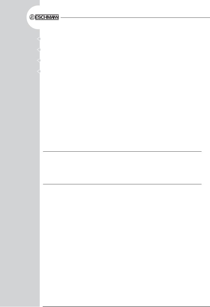
1. |
Water fill valve |
8. |
Reservoir drain tube |
2. |
Discharge valve |
9. |
Drain tap |
3. |
Pressure gauge |
10. |
Filter unit |
4. |
Chamber manifold |
11. |
Non-return valve |
5. |
Safety valve |
12. |
Reservoir float switch |
6. |
Test Valve |
13. |
Coil |
7.Pressure door lock
Fig. 3 Little Sister 3 Autoclave - pipelines and valves
Page 12 of 45 |
ST-TM4e |

SES Little Sister 3 - Technical Manual
TECHNICAL DESCRIPTION (contd)
(19)FUSIBLE LINK (Fig. 4 item 7). This is connected so as to remove power from the heater if a serious overheating condition should occur. Note however that operation of this device is unlikely to occur since the heating element is already protected by the heater cut-out. The fusible link thus acts as a ‘last resort’ device and is non-resetting.
(20)FUSES. The unit is provided with four fuses as follows:
(a)Three fuses on the rear panel of the cabinet (Fig. 4 items 9 and 10) rated as shown under TECHNICAL DATA. The two larger fuses are connected into the supply lines to the unit. The small fuse protects the primary circuit of the transformer.
(b)A fourth fuse, situated on the printed circuit board (Fig. 5 item 5) and rated at 2A, protects the secondary circuit of the transformer and parts of the controller.
(21)TRANSFORMER (Fig. 4 item 11). This converts the incoming mains voltage to 20V a.c. to operate the controller and the water fill and discharge valves. It is rated at 20VA. A thermal fuse is fitted in the secondary winding, this is not resettable and therefore a new transformer would be required. CHECK FOR SHORT CIRCUIT BEFORE FITTING.
(22)WATER FILLVALVE (Fig. 3 item 1). This valve is used to control the water filling sequence. It is electrically operated from a 24Vd.c. supply which is generated and signalled from the controller.
(23)DISCHARGE VALVE (Fig. 3 item 2). This valve is used principally at the end of the sterilizing cycle to allow water and steam from the chamber to pass back into the reservoir. It is also operated at various other times during the cycle. The valve is electrically operated from a 24V d.c. supply generated within the controller.
(24)AIRVALVE (Fig. 3 item 6).At the start of any cycle the chamber is full of air and for a satisfactory result almost all of this has to be removed. In the SES Little Sister 3 this is accomplished by means of a small air valve. This valve contains a ball and spring which allows air displaced by the steam generated in the chamber to pass out into the reservoir. Once steam starts to pass by the ball, the ball then lifts and seals. A small ‘bleed’ remains, however, and it is quite normal for small quantities of steam to escape into the reservoir throughout the cycle.
(25)SAFETYVALVE (Fig. 3 item 5). This is mounted on the manifold at the rear of the chamber and is factory set to lift at 2.6 bar in order to release excess pressure from within the chamber. It is a primary safety device and should not be readjusted.
(26)TEMPERATURE SENSOR (Fig. 4 item 4). This is used to sense the chamber temperature and is mounted on the manifold in a position where it is exposed to a small volume of steam bled through the air valve. The temperature sensor comprises a small electronic circuit (Analogue Devices type AD590JH) which produces a current proportional to temperature. This device with its associated leads, mounting plate, spring and connector together form a single assembly. The sensor is used to control the temperature within the chamber.
(27)TEMPERATURE SENSOR (Fig. 4 item 21). This is the same device as described under subpara. (26) and senses the chamber temperature in the same manner. This sensor, however, is used to display the chamber temperature and has no control function.
Note: Items 4 and 21 of Fig. 4 are identical. It is their point of connection on the controller board which determines either control or display function.
ST-TM4e |
Page 13 of 45 |
SES Little Sister 3 - Technical Manual
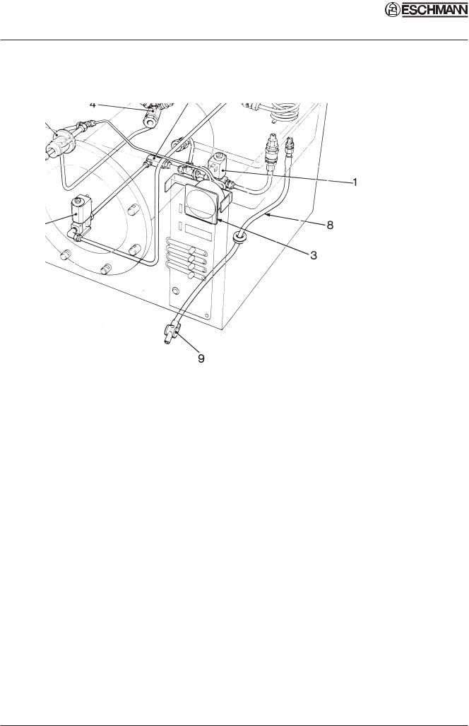
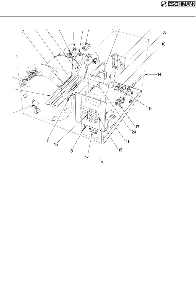
1. |
Heating element |
13. |
Terminal block |
2. |
Sensor (cycling thermostat) |
14. |
Power supply cable |
3. |
Switch (cycling thermostat) |
15. |
Programme selector buttons |
4. |
Temperature sensor (chamber control) |
16. |
Light emitting diodes (LED’s) |
5. |
Water level sensor |
17. |
Power on/off switch |
6. |
Door interlock microswitch |
18. |
Overheat warning lamp |
7. |
Thermal fuse |
19. |
Thermocouple entry port |
8. |
Mechanical relay |
20. |
Test Port |
9. |
Fuses (10A, 13A or 20A) |
21. |
Temperature sensor (display) |
10. |
Fuse (400mA or 800mA) |
22. |
Sensor (heater cut-out) |
11. |
Transformer |
23. |
Switch (heater cut-out) |
12. |
PCB (controller) |
24. |
Solid state relay |
|
|
25. |
Solenoid door lock |
Fig. 4 Little Sister 3 - Heater and process controls
Page 14 of 45 |
ST-TM4e |

SES Little Sister 3 - Technical Manual
TECHNICAL DESCRIPTION (contd)
(28)THERMOCOUPLE ENTRY PORT (Fig. 4 items 19 and 20). This can be used to introduce a thermocouple into the chamber ‘drain line’ to allow the operating temperature to be measured and adjusted if necessary. To ensure probe is not touching the capillary tube or the’bottom of the hole, withdraw probe approximately 3mm from the stop position.
(29)WATER DRAIN PIPE (Fig. 3 items 8 and 9). This provides a convenient means of emptying the reservoir for cleaning or prior to transportation.
(30)CONTROLLER (Fig. 4 item 12). The SES Little Sister 3 is provided with a fully integrated microprocessor-based controller. The controller handles every aspect of management of the machine which includes operation and control of the digital display, the light emitting diodes and response to the programme selection push buttons. The controller receives information from the temperature sensor and from the door interlock switch and is able to detect a variety of errors and the times relative to the cycle run when these occur. In addition to controlling the autoclave in the user mode, the controller also supports a ‘demonstration’ and an ‘engineering’ mode (see SPECIAL OPERATING MODES). The controller operates the heater via the solid state relay and also controls the operation of the water fill and discharge valves. A detailed knowledge of the operation of the controller is not necessary in order to service the autoclave; it is best regarded as a replaceable sub-assembly and should only be changed as a last resort.
(31)CYCLE COUNTER. The cycle counter displays the number of completed cycles to date for three seconds when power is first switched on, then for one second every fifteen seconds at other times. After commencement of a cycle the counter display will include that cycle in the total count.
DESCRIPTION OF OPERATION CYCLE
6. A detailed knowledge of every aspect of the operation of the SES Little Sister 3 is not necessary in order to be able to repair it effectively; nevertheless, a basic understanding of the various processes of the unit operation which take place during a cycle can be useful.
Unit Operation
7.Power to the unit is switched on by selecting the power switch ‘0-I’ to ‘I’, there now follows a single high-pitched audible signal accompanied by the display ‘test door’ flashing. Alternatively open door to proceed, ‘LS3’will now be displayed followed by ‘door’. If the door is not closed the display will show ‘LS3’ then ‘door’ when power is switched on.
8.After the work trays have been placed in the chamber and the door closed, the discharge valve is opened, ‘rEAdy’is displayed and LED’s on the programme selector panel flash on and off to indicate that a programme from those available* can now be selected and initiated by pressing one of the programme selector buttons.
* The unit is normally preset to offer a choice of two programmes at 134°C. This unit can be customised to suit the sterilizing requirements. (i.e. single temperature, part or whole programme).
9.When the door is closed, with power switched on, this is sensed by the controller via the door interlock switch. If any attempt is made to open the door once the cycle has commenced, the error display ‘Err 2’will appear, accompanied by an audible signal. Under these circumstances it is necessary to secure the door and cancel ‘Err 2’ display (see para. 25) and then re-start cycle.
ST-TM4e |
Page 15 of 45 |
 Loading...