

Easy setting for t
ibia nailing in horizontal or angled traction position. Use Eschmann
Converting T30 to
o
rthopaedic table or just adding orthopaed
ic traction using auto
Easy patient setting and full
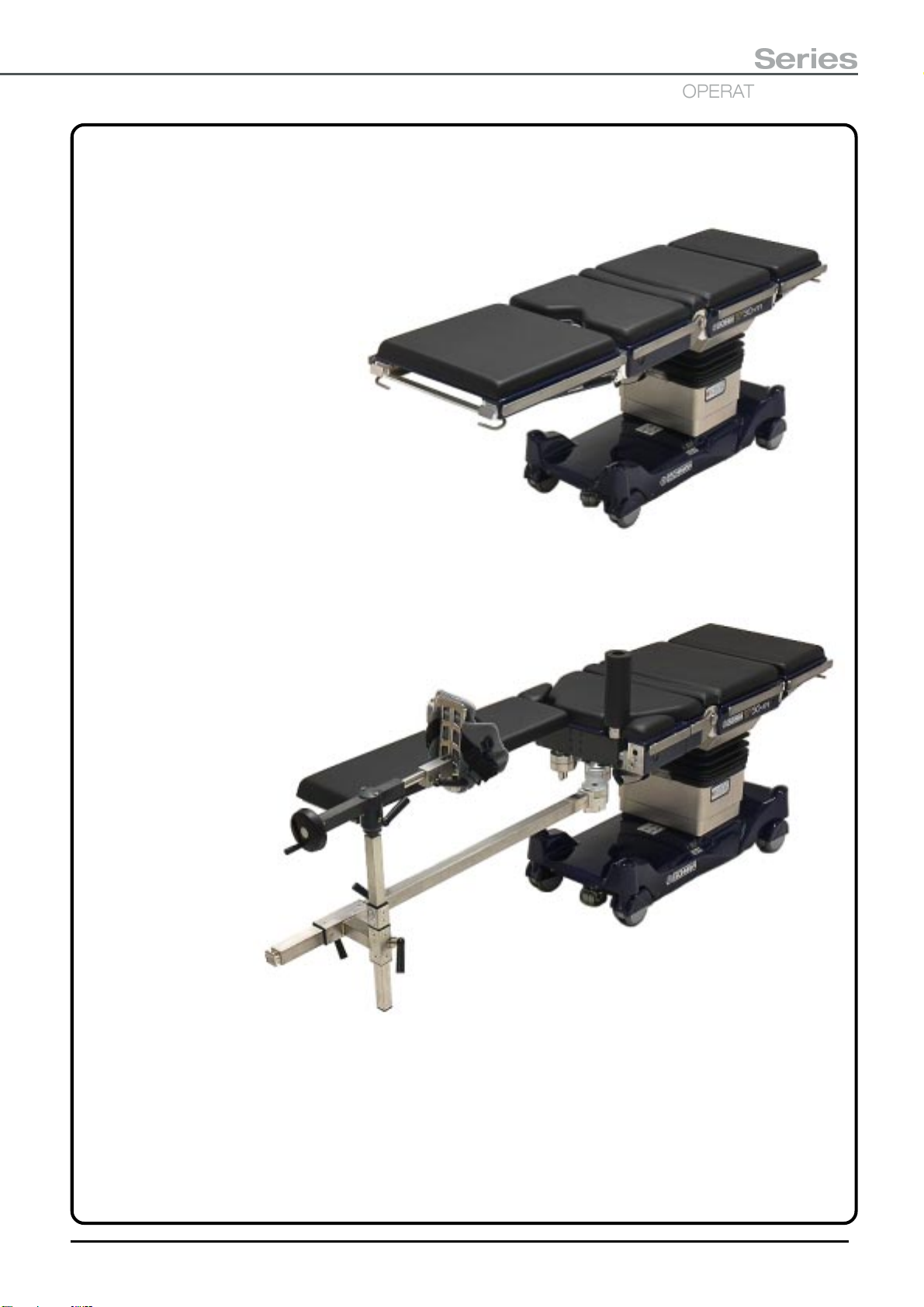
T30a/m
with
orthopaedic
attachment
self guiding docking trolley preventing risk of injury to operating room staff.
Offers option of single or double click-on traction beams with offset choice,
and leg support for trouble free patient setting and ultimate patient comfort.
Patient weight load of 200 kg on traction mode without support pole.
Optional accessory trolley
flexibility of X-ray imaging for
DHS procedures
T30 leg support or DP leg holder.
Large wheels option with single locking
with built
This literature should be read in
T30a/m 5/6 section Operation
table convertible to orthopaedic
and trauma table
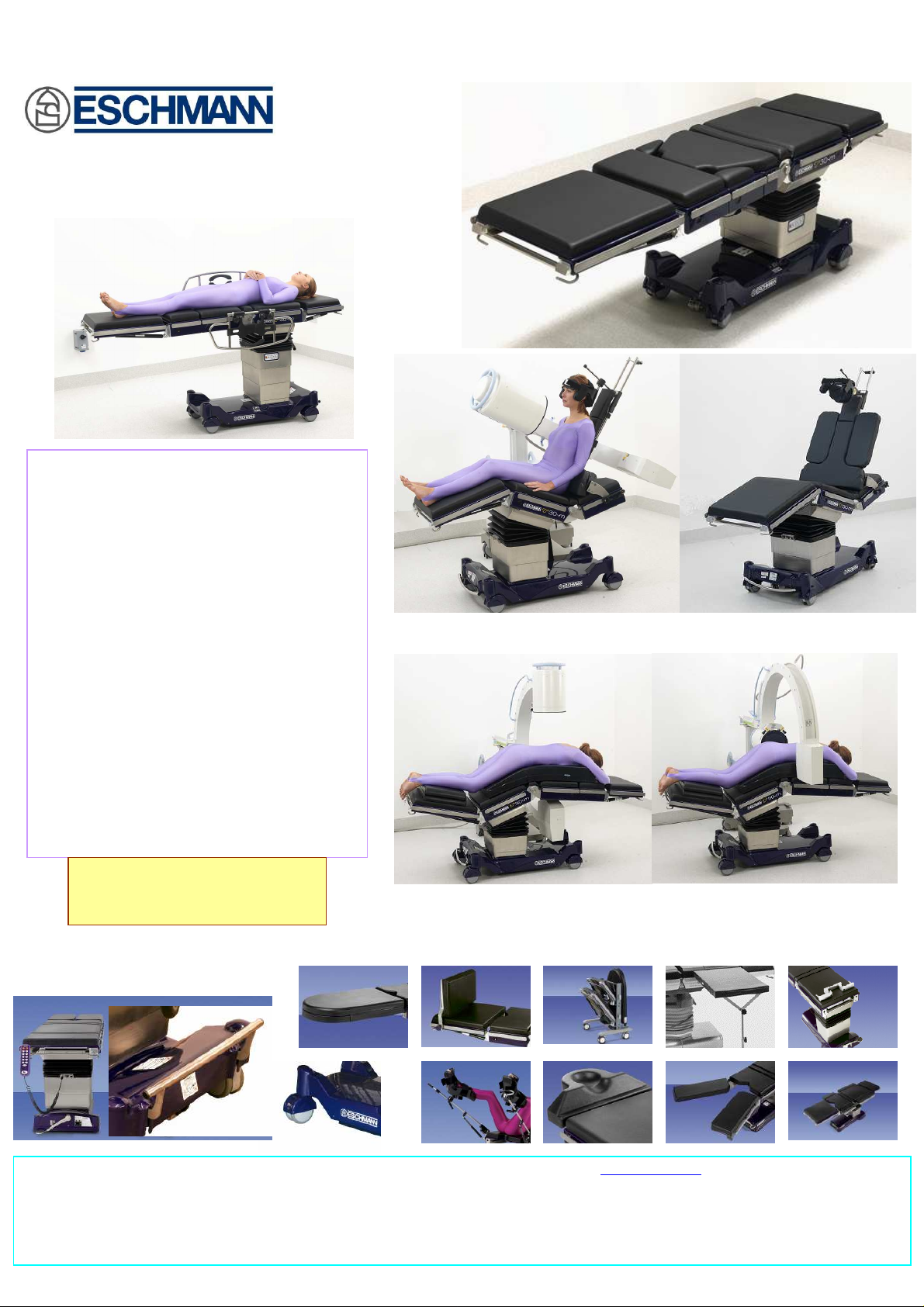
New generation, new concept,
completely versatile, all purpose
operation table
5 or 6 sections general and
specialised operation table
Fully X-ray translucent table top,
-in X-ray cassette tunnel
through the table top
Detachable and interchangeable
sections
Convertible to fully functional
orthopaedic and trauma table
Special designed shoulder surgery attachment for Eschmann “T” range
conjunction with EschmannT20
catalogue publicity No. PS-217c
pedal (T30m)
Small wheels with double pedal (T30a)
Eschmann Equipment, Peter Road, Lancing, West Sussex BN158TJ, England Tel: +44 1903 753322 Fax: +44 1903 875789 www.eschmann.co.uk
Asia Pacific: Eschmann Holdings Pte Ltd., 300 Beach Road, #32-07 The Concourse, Singapore 199555
Tel: +65 62983344 Fax: +65 62928918 Email: Eschmann_spore@pacific.net.sg
Details given in this leaflet are correct at the time of going to press. The Company however, reserves the right to improve or modify the equipment shown. The Eschmann name and
logo are trademarks Eschmann Holdings Ltd. Eschmann Equipment is a trading name of Eschmann Holdings Limited.
Optional accessories
Full X-ray imaging at lowest height for spinal surgery
T30a/m with orthopaedic attachment
New generation, new concept, completely versatile, all
purpose operation table
5 or 6 sections general and specialised operation table
Fully X-ray translucent table top, with built-in X-ray cassette
tunnel through the table top
Detachable and interchangeable sections
Convertible to fully functional orthopaedic and trauma table
Detachable, and click-on traction beams,
centre positioning with double joint
knuckles.
Two options of double pedal locking
mechanism, with standard wheels(T30a)
Tibia nailing downward traction
position
Large wheels option with single
locking pedal (T30m)
This literature should be read in
conjunction with EschmannT20
catalogue publicity No. PS-217c
Tibia Nailing in horizontal traction
position. Use Eschmann T30 leg
support or DP leg holder
Easy click-on docking cart with autolock mechanism
T30
Perennial
Post
Carbon Fibre
with
, Range Configuration and Specification
T30a and T30m
5 or 6 (with divided leg section) sections table top.
Features and specification as T20a/m, but without
transverse top
T30m, (single pedal
and large wheels)
Interchangeable
sections
5 Section T30a, (double pedals
& small wheels)
Orthopaedic Attachment for
T30a and T30m
Sacral Support
Docking Cart (optional)
Traction beam & T. assembly
Orthopaedic boot
Docking Cart
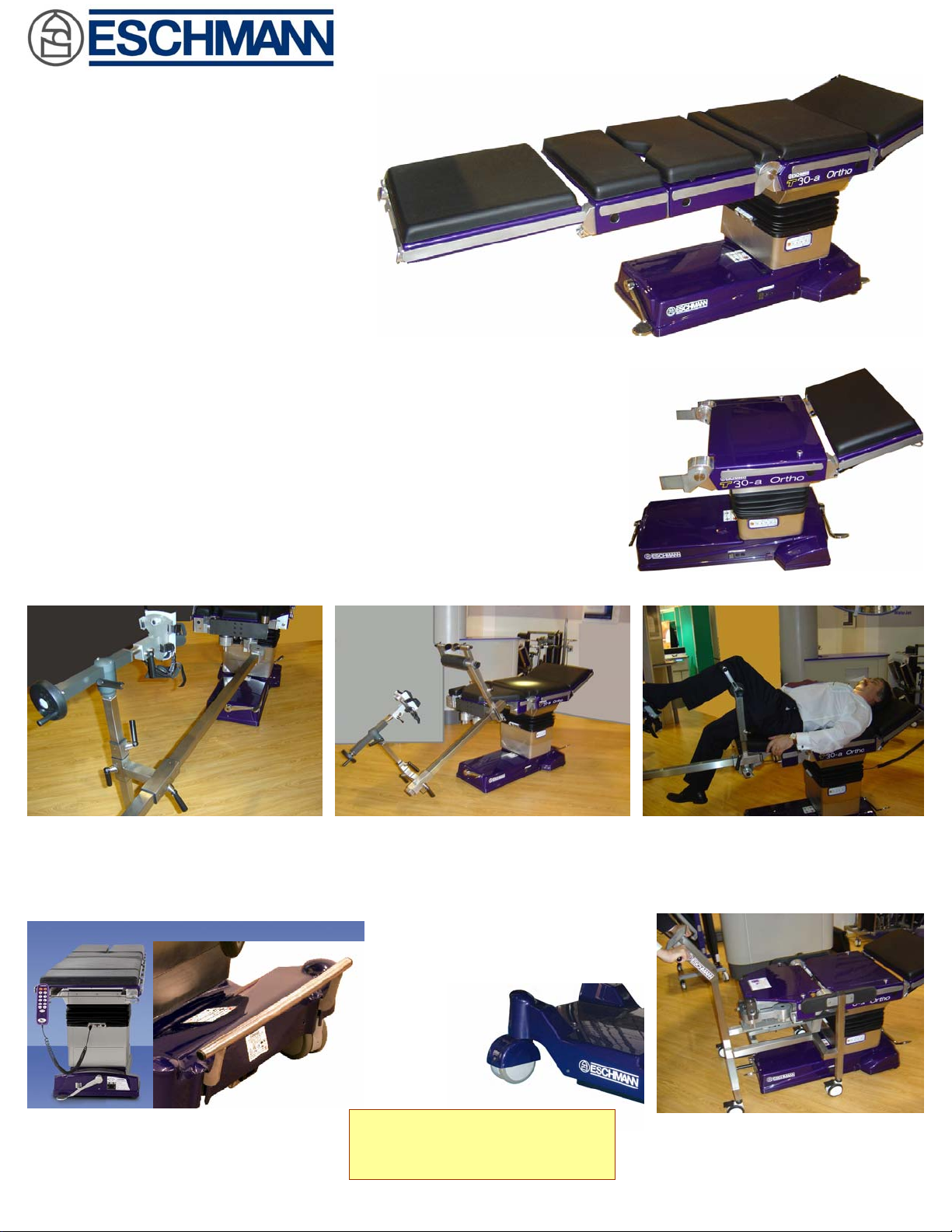
T30a/m-Ortho
An Orthopaedic and Trauma Operating Table complete
detachable double traction beams assembly, leg
supports, swivel joint knuckles, pair of adjustable booties,
carbon fibre perennial post,
convertible to 5 or 6 sections fully
X-ray translucent top general and
specialised operation table
Perennial Post
Carbon Fibre
Gynae & Urology with
perennial extension
Sacral assembly
Gynae & Urology
Traction Beam &
Traction Assembly
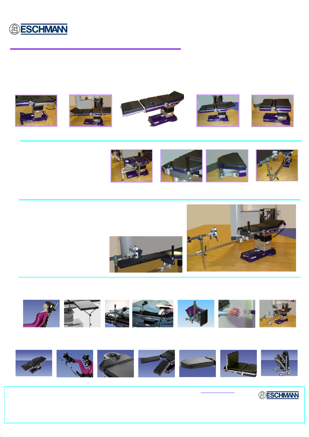
Optional accessories and attachments for Orthopaedic Surgery
Accessory Trolley Hip Fixation Accessories Hand Surgery Table Shoulder Chair
Optional accessories for General & Specialised Surgery
Width Extender
Eschmann Equipment, Peter Road, Lancing, West Sussex BN158TJ, England Tel: +44 1903 753322 Fax: +44 1903 875789 www.eschmann.co.uk
Asia Pacific: Eschmann Holdings Pte Ltd., 300 Beach Road, #32-07 The Concourse, Singapore 199555
Tel: +65 62983344 Fax: +65 62928918 Email: Eschmann_spore@pacific.net.sg
Details given in this leaflet are correct at the time of going to press. The Company however, reserves the right to improve or modify the equipment shown. The Eschmann name and
logo are trademarks Eschmann Holdings Ltd. Eschmann Equipment is a trading name of Eschmann Holdings Limited.
Hand Traction
Tibia Nailing Set
Accessory Trolley Foot Support Light weight Leg S Divided Leg S Ophthalmic Head S DP Leg Holder
T30
OPERATING TABLES
Series
Instructions for use
113364
T-IM122b

Read these Instructions before use
Keep these ‘Instructions for use’ in a safe convenient place for future reference.
Eschmann After Sales Service Department
The Eschmann After Sales Service Department is staffed and equipped to provide advice and
assistance during normal office hours. To avoid delays when making enquiries, please quote the
Model and Serial Number of your Operating Table which is shown on the Serial Number Plate
located on the table base (or the trunk section for the T30-m). Please ensure you include all
alpha and numeric digits of the Serial Number.
For further information visit www.eschmann.co.uk
All correspondence relating to the after sales service of Eschmann Equipment to be addressed to :
UK Customers
Eschmann Equipment, Peter Road, Lancing, West Sussex BN15 8TJ, England.
Tel: +44 (0) 1903 765040. Fax: +44 (0) 1903 875711.
Overseas Customers
Contact your local distributor. In case of doubt contact Eschmann Equipment.
Patents and Trade marks
The ESCHMANN name and logo; “T30-a” and “T30-m” are trade marks of Eschmann Holdings Limited.
“Eschmann Equipment” is a trading name of Eschmann Holdings Limited.
Patents : Worldwide Patents Pending.
Copyright © 2007 Eschmann Holdings Limited
All rights reserved. This booklet is protected by copyright. No part of it may be reproduced, stored in a
retrieval system or transmitted in any form or by any means, electronic, mechanical, photocopying,
recording or otherwise without written permission from Eschmann Holdings Limited.
The information in this publication was correct at the time of going to print. The Company, however,
reserves the right to modify or improve the equipment referred to.
The CE marking affixed to the product certifies that it complies with the European
Medical Devices Directive 93/42/EEC as amended and related legislation.
T-IM122b March 2007
Instructions for use
T30
OPERATING TABLES
Series
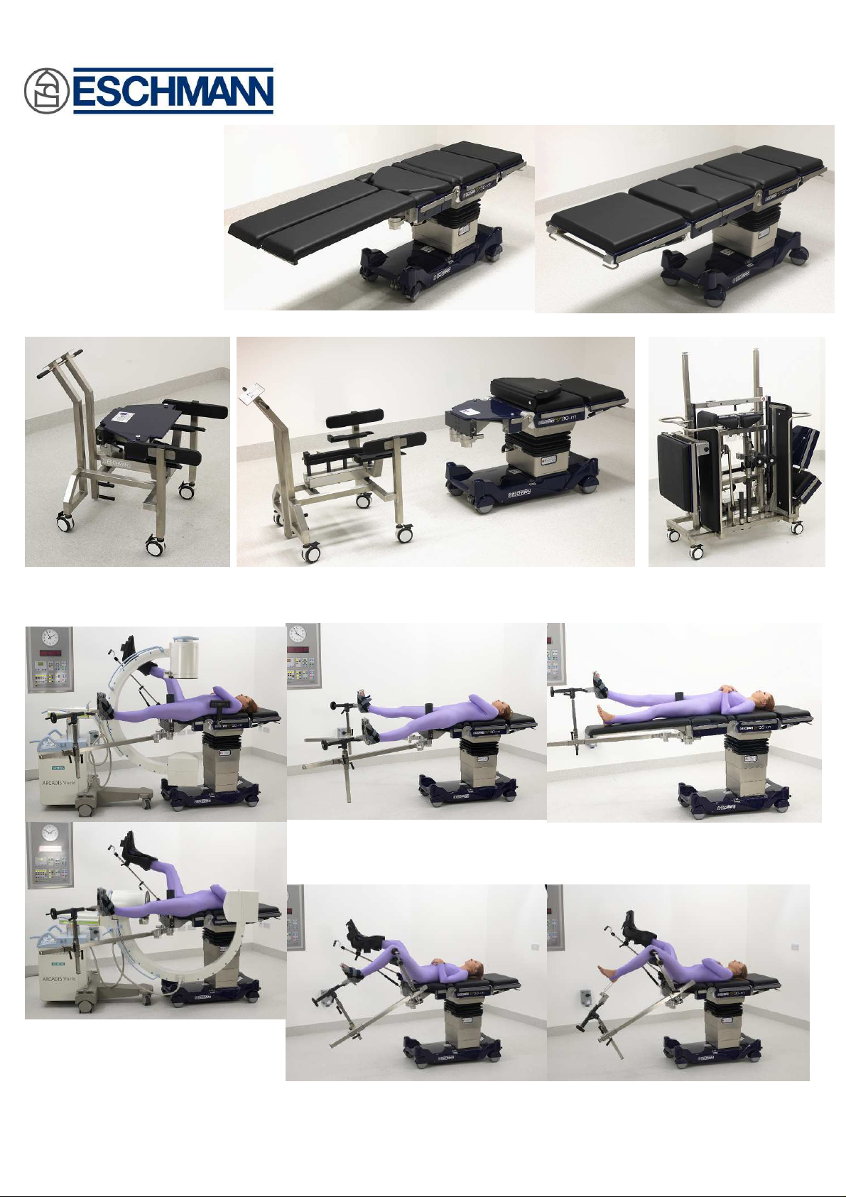
The T30 Series Operating Tables
The T30 powered operating table is a modular system suitable for
a full range of general, specialist and Orthopaedic surgical
procedures. A range of 4, 5 or 6 section tops are
available along with a superior range of additional
accessories to make this a truly versatile
general and specialist powered
operating table. With the simple
removal of the general surgical
lower trunk section, via a docking
cart, and the addition of a range of
orthopaedic accessories, the T30 can
easily be converted for a full range of
orthopaedic procedures.
TheT30 operating table has an X-ray translucent tabletop
with a built-in X-ray cassette tunnel. The slimline column is
offset relative to top and base for ease of C-arm access.
The T30 Table features a corded handset controlling Trendelenburg,
reverse Trendelenburg, lateral tilt, flexion/extension (including
90° chair position) and height. The handset also provides
a battery level indication.
The batteries in the table base are
mains rechargeable with a standby
battery in case of emergency.
Covers to the top and base
are purple and made
of a special scratch
resistant, hard-wearing
and easy to clean
seamless acrylic
capped ABS.
The mattress is moulded,
latex free and antistatic.
A choice of table
bases offers a
range of ergonomically
designed foot pedals to suit all
operating theatre environments. The T30-a pedals are located at the head and leg end of the
table base to provide braked, wheel (move in a straight line) and 360° mobility. The T30-a is
capable of supporting a maximum patient weight of 300kg or 135kg when moved around the
theatre.
The T30-m single foot pedal is located at the head end of the table and has three positions to
enable the table to be static (braked), rotated 360° or moved in a straight line. The T30-m is
capable of supporting a maximum patient weight of 300kg or 200kg when moved around the
theatre.
T30-m in a typical
orthopaedic configuration
T30-m in a typical
general surgical
configuration
T-IM122b P3/77

CONTENTS
1.0 PRELIMINARY INFORMATION ..............6
1.1 General ....................................................... 6
1.2 About this manual.......................................... 6
1.3 Table description ........................................... 7
2.0 TABLE PARTS AND SYMBOLS ............. 8
2.1 Part identification ........................................... 8
2.2 Symbols and graphics ................................... 8
2.2.1 Symbols general ...................................... 8
2.2.2 Handset button symbols ........................... 9
2.2.3 Handset graphics ..................................... 9
2.2.4 Standby control panel button symbols ...... 9
3.0 INSTALLATION ...................................12
3.1 General ..................................................... 12
3.2 Lifting the operating table ............................ 13
3.3 Technical ..................................................... 13
4.0 SAFETY NOTES & CAUTIONS ............ 15
4.1 Warnings ..................................................... 15
4.2 Do’s and Don’ts ........................................... 16
4.3 Daily ‘Before use’ test.................................. 16
4.4 Accessories................................................. 17
4.5 Manual handling .......................................... 17
5.0 OPERATING THE TABLE ................... 18
5.1 Moving/Operating the table base ................. 18
5.1.1 T30-a Table base ................................... 18
5.1.1.1 ‘Wheel’ orientation (from ‘braked’) 18
5.1.1.2 ‘Castor’ orientation (from ‘wheel’) . 18
5.1.1.3 ‘Castor’ orientation (from ‘braked’) 19
5.1.1.4 ‘Braked’ orientation ...................... 19
5.1.2 T30-m Table base .................................. 20
5.1.2.1 Foot pedal operation .................... 20
5.1.2.2 ‘Braked’ ........................................ 20
5.1.2.3 ‘Castor’ mode ............................... 20
5.1.2.4 ‘Wheel’ mode ............................... 20
5.1.3 Moving the table with a patient ............... 22
5.2 Using the removable sections. .................... 23
5.2.1 Realigning a section’s pins ..................... 23
5.2.2 Attaching a head, leg or infill section ...... 23
5.2.3 Removing a head, leg or infill section ..... 24
5.2.4 Head and leg section adjustment ........... 24
5.2.5 Changing the short trunk section ............ 24
5.2.5.1 Table prep’n, changing short trunk 25
5.2.5.2 G. Surgical to Ortho short trunk .... 25
5.2.5.3 Ortho to G. Surgical short trunk.... 26
5.2.5.4 Changing Ortho trunk manually .... 26
5.2.6 Docking cart preparation ........................ 26
5.2.7 Attaching/removing hip sections ............. 27
5.2.8 Attaching/removing pre-operative legs ... 27
5.2.9 Changing sections during a procedure ... 27
5.2.10Attaching/Removing mattresses ............. 27
5.2.10.1 Sections with mushroom pins ....... 27
5.2.10.2 Hip & pre-operative leg sections .. 28
5.3 Powered and electrical functions. ................ 28
5.3.1 Batteries and mains................................ 28
5.3.1.1 Battery charging introduction........ 28
5.3.1.2 Battery charging ........................... 29
5.3.1.3 Battery changing .......................... 29
5.3.1.4 Standby batteries ......................... 29
5.3.2 Powered motions ................................... 30
5.3.2.1 General ........................................ 30
5.3.2.2 Tabletop motions .......................... 30
5.3.3 Using the handset .................................. 31
5.3.3.1 General ........................................ 31
5.3.3.2 Handset button functions.............. 31
5.3.4 Using the standby control panel ............. 33
5.3.5 Fuse replacement .................................. 34
6.0 PATIENT POSITIONING .....................35
6.1 General ..................................................... 35
6.2 Treatment of the obese patient .................... 35
6.3 Radiographic procedures ............................ 35
6.4 Table positions and safe loading ................. 35
6.5 Table top configurations .............................. 45
7.0 ACCESSORIES ................................... 46
8.0 AFTER USE, CLEANING & CARE ...... 48
8.1 After use procedures ................................... 48
8.2 Cleaning ..................................................... 48
8.2.1 Operating table and accessories ............ 48
8.2.2 Mattresses and pads .............................. 48
8.3 Disinfection .................................................. 49
8.3.1 Disinfection procedure............................ 49
8.3.2 Table, accessories mattresses and pads 49
8.4 Care ..................................................... 49
8.5 Storing the operating table (long term) ........ 50
8.6 Maintenance ................................................ 50
8.6.1 General .................................................. 50
8.6.2 Fault diagnosis ....................................... 50
8.6.3 Environmental considerations ................ 50
8.6.4 Technical Lifetime .................................. 50
TABLE 1 - FAULT DIAGNOSIS............................. 52
9.0 TECHNICAL DATA .............................. 54
9.1 Weights ..................................................... 54
9.2 Dimensions ................................................. 54
9.3 Movements.................................................. 54
9.4 Table loading ............................................... 54
9.5 Electrical ..................................................... 54
9.6 Classification and symbology ...................... 56
9.7 Use with other equipment ............................ 56
9.8 Standards compliance ................................. 56
9.9 Environmental conditions ............................ 56
9.10 Alarms ..................................................... 56
9.11 Electromagnetic compatibility (EMC) ........... 57
P4/77 T-IM122b

T30
Series
OPERATING TABLES
FIGURES AND APPENDICES
Fig. 2.1 Part identification of the T30 Table tops. ...............................................................................10
Fig. 2.2 Part identification of the T30 Table base and column. ...........................................................11
Fig. 3.1 Lifting the T30 Table ..............................................................................................................13
Fig. 5.1 Lowering a T30-a Table’s pedal ............................................................................................19
Fig. 5.2 Raising a T30-a Table’s pedal ...............................................................................................19
Fig. 5.3 T30-a Table’s foot pedal, quick reference guide....................................................................19
Fig. 5.4 Operating the T30-m Table base...........................................................................................21
Fig. 5.5 Alternative table position for moving table with a patient .......................................................22
Fig. 5.6 Section pin alignment ............................................................................................................23
Fig. 5.7 Aligning section pre-attachment ............................................................................................24
Fig. 5.8 Removing a table section ......................................................................................................24
Fig. 5.9 Adjusting a head or leg section..............................................................................................25
Fig. 5.10 Trunk, infill and hip sections ..................................................................................................25
Fig. 5.11 Aligning the docking cart to attach the orthopaedic short trunk. ............................................25
Fig. 5.12 Red indicators on stubs .........................................................................................................26
Fig. 5.13 Parts of the hip section ..........................................................................................................26
Fig. 5.14 Attaching a hip section ...........................................................................................................26
Fig. 5.15 Attaching a pre-operative ......................................................................................................27
Fig. 5.16 Mattress screw location, hip and pre-operative leg ............................................................... 28
Fig. 5.17 Handset and charging indicators ...........................................................................................29
Fig. 5.18 Controller sockets and release buttons .................................................................................31
Fig. 5.19 Handset button functions and serial labels ............................................................................32
Fig. 5.20 Standby control panel ............................................................................................................33
Fig. 6.1 Approximate patient weight distributions ...............................................................................35
Fig. 6.2 Patient positioning for radiographic procedures .................................................................... 36
Fig. 6.3 Maximum patient weight v table position graphs (general surgical configurations) ...............37
Fig. 6.4 Maximum patient weight v table position graphs (orthopaedic configuration) ....................... 38
Fig. 6.5 Patient in various ‘Supine’ positions ......................................................................................39
Fig. 6.6 Patient in various ‘Prone’ positions ........................................................................................40
Fig. 6.7 Patient in various ‘Lawn chair’ & ‘Trendelenburg’ positions...................................................41
Fig. 6.8 Patient in various ‘Chair’ positions ......................................................................................... 42
Fig. 6.9 Patient in various ‘Proctology’ positions ................................................................................43
Fig. 6.10 Patient in ‘Lithotomy’, ‘Prone Laminectomy’ and ‘Lateral Nephrectomy’ ...............................44
Fig. 9.1 Major dimensions and movements .......................................................................................55
APPENDIX 1 - Training log ......................................................................................................................60
APPENDIX 2 - Decontamination certificate..............................................................................................61
APPENDIX 3 - Battery management........................................................................................................ 62
APPENDIX 4 - Manual handling safety notes and advice ........................................................................ 63
APPENDIX 5 - The traction accessories ..................................................................................................65
APPENDIX 6 - The Tibial Nailing Accessory............................................................................................68
APPENDIX 7 - The Lateral Femoral Nailing Accessory ...........................................................................70
APPENDIX 8 - The orthopaedic accessory trolley ...................................................................................72
APPENDIX 9 - Orthopaedic accessory and spares list ............................................................................74
APPENDIX 10 - Orthopaedic positioning and imaging procedures.......................................................... 75
T-IM122b P5/77

1.0 PRELIMINARY INFORMATION
WARNING
Read this preliminary information carefully and
note ALL of the warnings, cautions and safety
notes contained within these ‘Instructions for
use’ before using this Operating Table. Keep
these ‘Instructions for use’ close-to-hand at all
times for reference.
1.1 General
1.1.1 The T30 Tables are classified as battery
powered, mobile, general purpose and orthopaedic
operating tables. Their intended function is to support and
position a patient, in conjunction with their associated
accessories, during general surgical and orthopaedic
operations and procedures in an operating theatre. Their
intended application is for use by medically qualified
personnel, trained in the use of the T30 Tables, during
surgical operations and procedures in accordance with
these instructions.
1.1.2 These ‘Instructions for Use’ should be referred to
for details of the following T30 Tables, see the table’s Serial
Number Plate for the actual table Serial Number and REF
No.:
T30-a Catalogue (REF) number prefixed TOR2
Serial Numbers (SN) prefixed TAOA* or above.
T30-m Catalogue (REF) number prefixed TOR2
Serial Numbers (SN) prefixed TMOA* or above.
* The last letter of the SN prefix is the design modification
state, this may increase during the build life of the tables.
NOTE: Some models have ‘Denyer’, ‘USA’, or ‘Euro (Kifa)’
accessory sidebars. Standard UK Eschmann accessories
that locate onto these may not fit, please check with
Eschmann Equipment before purchasing accessories.
1.1.3 T30 Tables and accessories must only be used
as detailed within these ‘Instructions for use’. Failure to do
so could result in injury to patients or users, or damage to
the operating table and accessories. Always ensure that
all warnings and cautions detailed within these ‘Instructions
for use’, are strictly complied with. Appendix 1 is provided
for Hospitals that wish to keep a log of those people trained
in the safe use of this table. Eschmann Equipment offers
full training in the safe use of these tables, please contact
our After Sales Service Department, Tel. +44 (0) 1903
765040 for details.
1.1.4 ‘Instructions for use’ and ‘Service manuals’ (see
section 3.3.9) as applicable should be readily accessible
for reference prior to and when operating, cleaning and
servicing the operating table. All manuals are available from
Eschmann Equipment, see inside front cover for address.
1.1.5 Ensure the table has been correctly installed
before starting to use it, see section 3.0.
1.1.6 Ensure that these operating tables and
accessories are regularly serviced and checked for safety
at least every six months. All servicing and maintenance
procedures should be carried out by engineers who have
been trained by Eschmann. Training, a Service, or a Service
Contract can be arranged through our After Sales Service
Department [Tel. +44 (0) 1903 765040]. Do not remove
the table covers at any time (danger of accessible mains
voltage), this should only be carried out during maintenance
procedures.
1.2 About this manual
1.2.1 Within the text of these ‘Instructions for use’ the
following terminology is used:
i)
Normal patient orientation.
head section in a supine position, with the table in its
normal configuration.
ii)
Normal table configuration.
trunk section fitted, infill section fitted to long trunk,
head section fitted to infill section, leg section fitted
to general surgical short trunk (see Fig. 2.1).
iii)
Orthopaedic configuration.
section fitted with hip and pre-operative (split) leg
sections attached (see Fig. 2.1).
iv)
Left and right
the side of the table when viewed from the head
end with the table in its normal configuration.
v)
Auto-level
the automatic sequence of movements to return the
table to a preprogrammed position by pressing and
holding a single handset button. This does not affect
the head or leg sections, or any other manual or
powered accessory, fitted to the table.
vi)
LEDs.
This abbreviation is used when referring to
the various indicator lights on the table or handset
which are light emitting diodes (LEDs).
vii) The term T30 Table is used to cover both the T30-a
and the T30-m version of these operating tables.
1.2.2 These ‘Instructions for use’ have been split into
specific sections for ease of finding information (see the
main headings in ‘Contents’). Where applicable and within
each section, adequate cross references to other sections
are made to eliminate the need to duplicate information.
Orthopaedic procedures and table set up are covered in
Appendix 5 onwards
1.2.3 Section 5 (Operation) details how to use the T30
Tables and operate their controls correctly. It is strongly
recommended that the user has read and is familiar with
sections 1, 2 and 4 before passing onto section 5 and
starting to use this operating table.
1.2.4 Within this manual the sections in bold type
headed ‘WARNING’ give guidance on possible actions that
could lead to injury of the patient, or theatre staff, and
potential damage to the operating table. Sections headed
‘CAUTION’ give guidance on possible actions that could
lead to damage of this operating table which could then
lead to injury of the patient, or theatre staff.
. The terms ‘left’ and ‘right’ refer to
. The term ‘auto-level’ is used to describe
.
Patient’s head on the
General surgical short
Orthopaedic short trunk
P6/77 T-IM122b

T30
OPERATING TABLES
Series
1.3 Table description
1.3.1 T30 Tables have been designed to provide
facilities for General Surgery* and Orthopaedic Surgery**
with traction, they allow for intra-operative radiography
using a C-arm image intensifier.
* including Minimal Access procedures, Urology and
Gynaecology, Thoracic, Ophthalmic and ENT,
Neurosurgery, Plastic and Maxillo-Facial surgery.
** including dynamic hip screw (DHS) in the supine
position, femoral nailing in the supine position,
femoral nailing in the lateral position, femoral
reconstructive nailing in the supine position,
retrograde femoral nailing, tibial nailing, humeral
nailing and shoulder arthroscopy.
1.3.2 T30 Tables are stable, rigid in use and the robust
construction provides protection from patient trolley or
C-arm knocks whilst still providing easy access for
servicing. Careful design has minimised traps for potential
contamination and stops fluid entering the table during
normal use, cleaning and disinfection procedures.
1.3.3 Tabletop movements (i.e. Trendelenburg, height,
tilt and break) are electrically powered and incorporate ‘soft
start and stop’ motions for patient comfort and safety. The
pedestal base is foot operated and the standard head and
leg sections are hand operated (see sections 5.1 and 5.2
respectively). All orthopaedic accessories are manually
adjusted and operated.
1.3.4 T30 Tables are easy to operate, theatre staff can
quickly learn how to use them correctly and safely. Tabletop
control is provided by a corded handset, or an optional
footswitch (for Trendelenburg and height control only).
Handset control overrides footswitch control at all times.
1.3.5 Power for all powered table movements is
provided by internal rechargeable batteries. There are two
battery sets, main batteries and standby batteries. These
are recharged by an internal battery charger which requires
connection to mains voltage using the mains cord supplied.
Note: If the main table batteries fail or become critically
low (i.e. warning indicators were ignored and batteries have
not been recharged) the table cannot be powered directly
from the mains. However by depressing and holding the
standby battery switch, powered table movements can
again be achieved (using power from standby batteries).
1.3.6 In emergencies (e.g. handset failure or a critically
low battery) a standby control panel on the column can be
used to control the table (however this MUST be limited to
emergency use ONLY, certain safety features are overridden when this panel is used, see section 5.3.4). It may
be required to press the standby battery switch if the main
battery charge level is too low.
1.3.7 The base on the T30-a Table is fitted with
enclosed multidirectional castors and has two foot pedals.
The T30-m Table is provided with four large castors that
can be adjusted by a single foot pedal. The castors on all
models can provide either castor, wheel or braked
orientations (see section 5.1).
1.3.8 Visual indicators have been restricted to essential
functions and information only (e.g. table switched ‘on’ see
section 5.3.2.2, battery level indication and battery charging
state see section 5.3.1). Audible signals are only used to
signal that the table has been switched ‘on’ for a long time
without operation and that it should be switched ‘off’, see
section 8.1 (this inactivity ‘beep’ can be configured ‘off’
during a service if required), a ‘beep’ is also provided when
switching ‘on’.
1.3.9 Tabletops have a lightweight X-ray translucent
surface (designed to reduce shadows on images) and an
X-ray cassette tunnel with the facility for an X-ray cassette
(430mm x 340mm) to be placed at any point beneath the
full length of the patient’s body, see section 6.3. The
standard sidebars allow placement of clamps and most
standard accessories. Simple buttons or catches release
the head, leg, hip, pre-operative leg, infill and short trunk
sections.
1.3.10 The tabletop can be adjusted into the following
patient positions (Note: Orthopaedic positions are detailed
in Appendix 5 onwards):
♦ Supine with C-arm access to patient from nipple
region to feet
♦ Supine with C-arm access to patient from groin to
head
♦ Supine Extension with C-arm access to break area
(Cholecystectomy-type procedure)
♦ Supine Flexion (‘Lawn chair’ position)
♦ Lateral
♦ Lateral Extension with C-arm access to break
(Nephrectomy position)
♦ Supine Lithotomy with C-arm access to whole of
the Urinary tract
♦ Supine Lithotomy with or without Trendelenburg
♦ Prone with or without extension at waist or hips (with
C-arm access)
♦ 90° Chair position with patient’s knees at the same
level as the heart, offset to the head end.
1.3.11 For additional information see section 6.0 for
patient positioning notes, section 6.2 for obese patients,
6.3 for radiographic procedures and 6.4 for illustrations
and details of safe loading. Tabletop configurations are
shown pictorily in section 6.5.
T-IM122b P7/77
2.0 TABLE PARTS AND SYMBOLS
REF This symbol indicates the catalogue number is
as indicated adjacent to the symbol.
2.1 Part identification
2.1.1 Fig. 2.1 shows the T30-a and T30-m Table tops
in their normal configuration and identifies the major parts
of the tabletop.
2.1.2 Fig. 2.2 identifies the various parts of the T30-a
and the T30-m Table base and column.
2.1.3 Orthopaedic accessories and components are
detailed in Appendix 5 onwards.
2.2 Symbols and graphics
To enable an easy reference to all the symbols and graphics
used on the T30 Tables (and within these ‘Instructions for
use’) the following grouped sections show all the symbols
and graphics used.
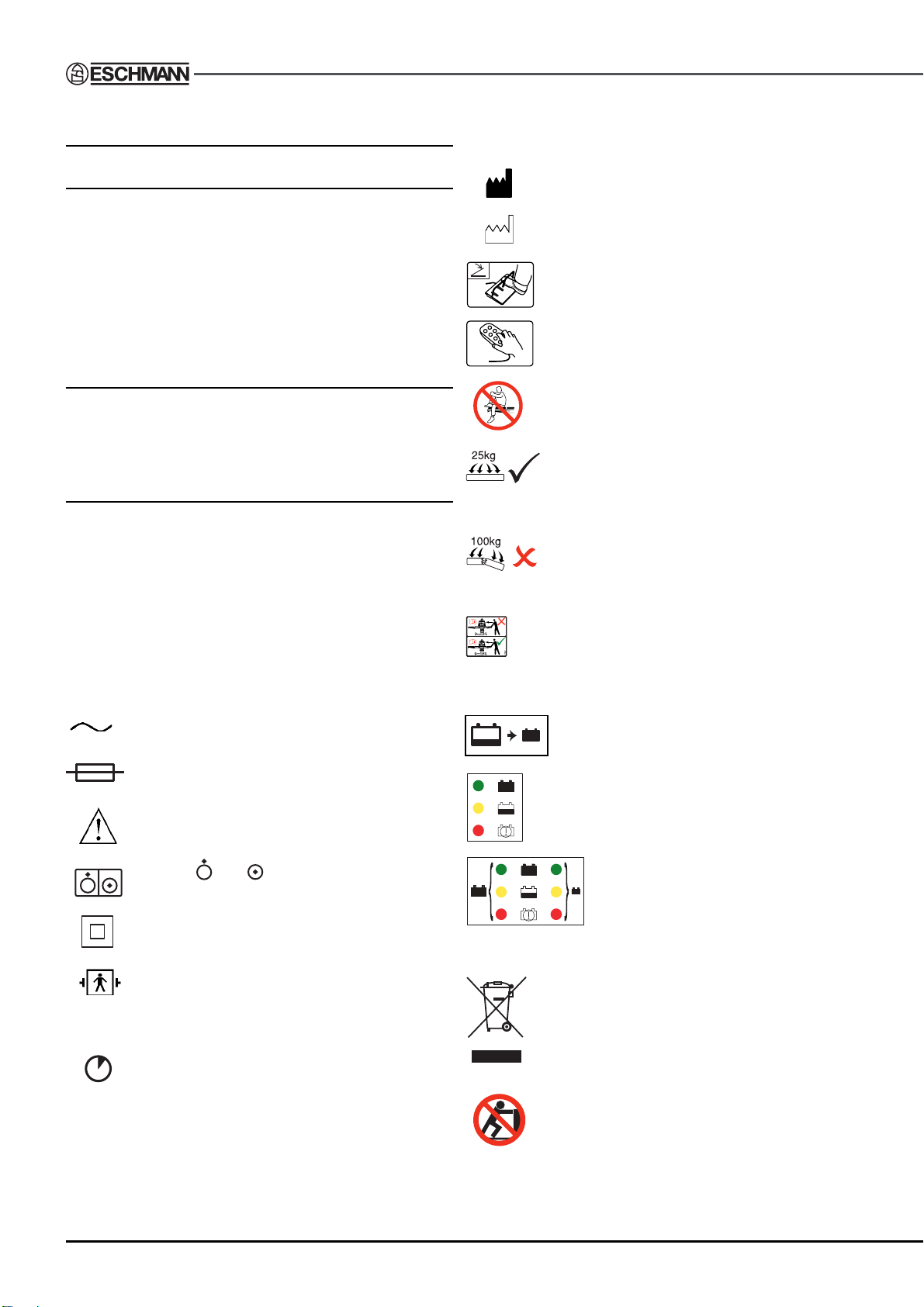
2.2.1 Symbols general
The following symbols are shown on various parts of the
table, handset or Serial Number Plate.
IPX 4 This symbol (splash proof) denotes that the
equipment (the table) meets the requirements of IEC529
for protection from splashing water.
IPX 6 This symbol (protection against heavy seas) denotes
that the equipment (the handset) meets the requirements
of IEC529 in that water from heavy seas or water projected
from powerful jets shall not enter in harmful quantities.
This symbol indicates that the equipment is for
use on alternating current.
This symbol indicates that fuses adjacent to the
symbol have a rating and type as detailed.
This symbol warns the user to read the accompanying documents, these ‘Instructions for use’.
This symbol indicates that the manufacturer is
as indicated adjacent to the symbol.
This symbol indicates that the date of manufacture is as indicated adjacent to the symbol.
This symbol indicates the connection point for
a footswitch.
This symbol indicates the connection point for
the corded handset.
This symbol indicates that the table section
to which it is applied (e.g. head section, under
the mattress) should not be used as a seat.
This symbol indicates the ‘Safe working load’
of the section to which it is applied can safely
support an evenly distributed load to the value
indicated, in this example 25kg.
This symbol indicates the ‘Minimum breaking
load’ of the section to which it is applied. An
evenly distributed load (in this example 100kg
or greater) may break the section.
This symbol on the table base indicates the
maximum weight that can be placed on the
table when static and braked, or being moved
around the theatre (see section 6.4 for more
information).
This symbol is used to identify the standby
battery switch.
113150-01
This graphic (T30-m Table only) adjacent to the
mains socket, identifies the relationship between
the colour of the mains ‘on’ LED and the battery
charge state, see section 5.3.1.
Symbols and near the main table ‘on/off’
switch, indicate ‘OFF’ and ‘ON’ respectively.
With the mains cord attached the equipment has
‘Class II’ protection against electric shock.
The patient leakage current, with mains voltage
on the applied parts, meets the requirement for
type BF medical electrical equipment and are
defibrillator proof.
This symbol is used to indicate the table’s duty
cycle which is the ratio of the operating time to
the sum of the operating time and the ensuing
interval.
SN This symbol indicates the unit serial number is
as indicated adjacent to the symbol.
This symbol indicates that this product was
placed on the market after 13th August 2005. At
the end of its working life it should be deposited
at an appropriate facility to enable recycling. For
information on how to recycle this product
responsibly contact Eschmann.
Pushing prohibited. This symbol, on the trolley,
indicates that it should not be pushed from the
side on which the symbol is attached.
This graphic (T30-a Table only)
adjacent to the mains socket, identifies
the relationship between the colour of
the mains ‘on’ LED and the battery
charge state for the main and standby
batteries, see section 5.3.1.
P8/77 T-IM122b
T30
OPERATING TABLES
Series
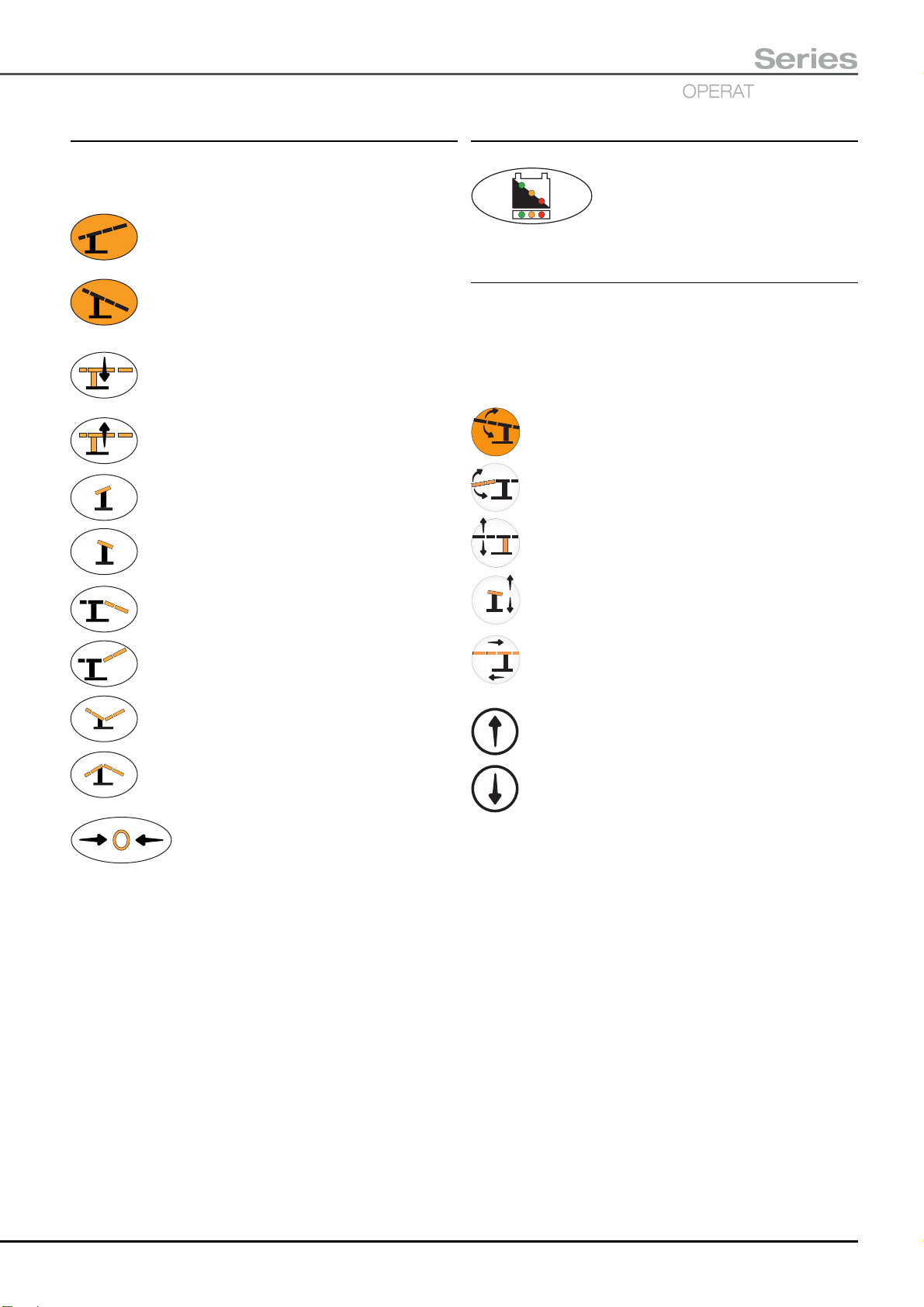
2.2.2 Handset button symbols
The following symbols are shown on the handset buttons
to indicate their function. Use of the handset is fully detailed
in section 5.3.3 of this manual.
Trendelenburg - Press to adjust tabletop in the
Trendelenburg (head down) direction.
Reverse Trendelenburg - Press to adjust
tabletop in the Reverse Trendelenburg (head
up) direction.
Height down - Press to move tabletop down.
Height up - Press to move tabletop up.
Tilt - Press to tilt tabletop down on the left (when
viewed from the long trunk end)
Tilt - Press to tilt tabletop down on the right
(when viewed from the long trunk end)
2.2.3 Handset graphics
This graphic is shown on the corded
handset to indicate the battery charge
level for both the main and standby
batteries, see section 5.3.1.
2.2.4 Standby control panel button symbols
The following symbols are shown on the standby control
panel buttons, indicating the function they select. The
arrows (upper or lower) indicate the direction the selected
function will move, if the corresponding direction button
(i.e. upper or lower) is pressed, see section 5.3.4.
Button selects Trendelenburg function.
Button selects Break function.
Button selects Height function.
Break down - Press to move the break down
(i.e. short trunk moves down w.r.t. long trunk)
Break up - Press to move the break up
(i.e. short trunk moves up w.r.t. long trunk)
Flexion - Press to move tabletop into Flexion.
Extension - Press to move table into Extension.
Return to Level - Press to return tabletop
to a preset level position.
Button selects Tilt function.
Non functional Button (selects Traverse function
on other tables in the ‘T’ series).
Direction button - Press button to obtain movement
indicated by upper arrow of function button.
Direction button - Press button to obtain movement
indicated by lower arrow of function button.
T-IM122b P9/77
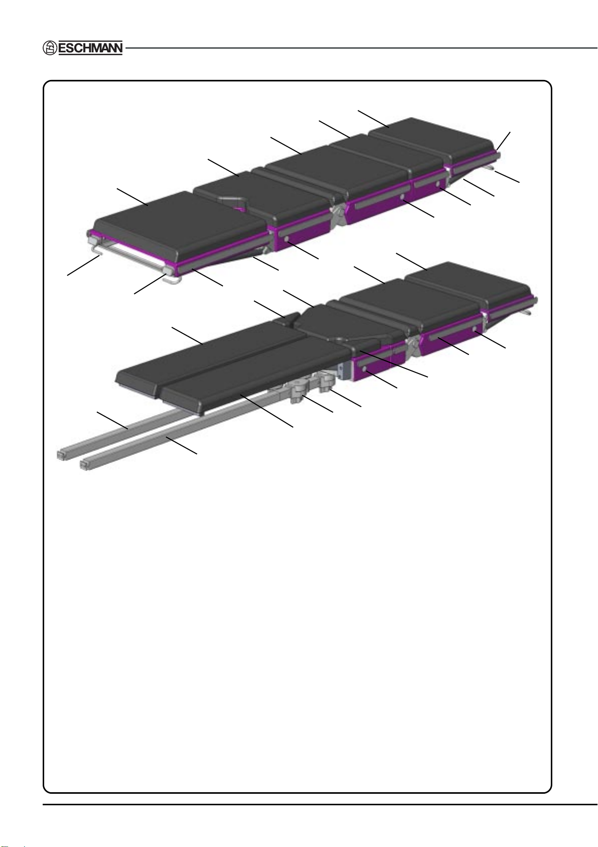
TYPICAL GENERAL SURGICAL
TABLETOP ARRANGEMENT
Note: The infill section can be removed, or be
positioned between the leg and short trunk
section. The leg section shown can be replaced
by a divided (split) leg section.
3
1
5
2
11
16
17
8
9
9
1
9
2
10
4
6
12
6
9
18
19
7
TYPICAL ORTHOPAEDIC
13
12
7
14
15
9
TABLETOP ARRANGEMENT
17
1 Head section
2 Long trunk section
3 General surgical short trunk section
4 Orthopaedic short trunk section
5 Infill section
6 Hip sections
7 Pre-operative leg sections
8 Leg section
9 Section release buttons
10 Leg section gas spring
11 Head section end block (use to stow UK/EURO handset)
12 Accessory sidebar (can also be used to stow handset*)
13 End block, also on head section (use to stow UK/EURO handset)
14 Head section release bar
15 Head section gas spring
16 Leg section release bar
17 Traction beam
18 Fixed knuckle
19 Intermediate knuckle
* Clip on handset must match sidebar type, see accessory section 4.8
Fig. 2.1 Part identification of the T30 Table tops.
P10/77 T-IM122b
T30
OPERATING TABLES
Series
10
5
3
1
4
2
6
87
9
13
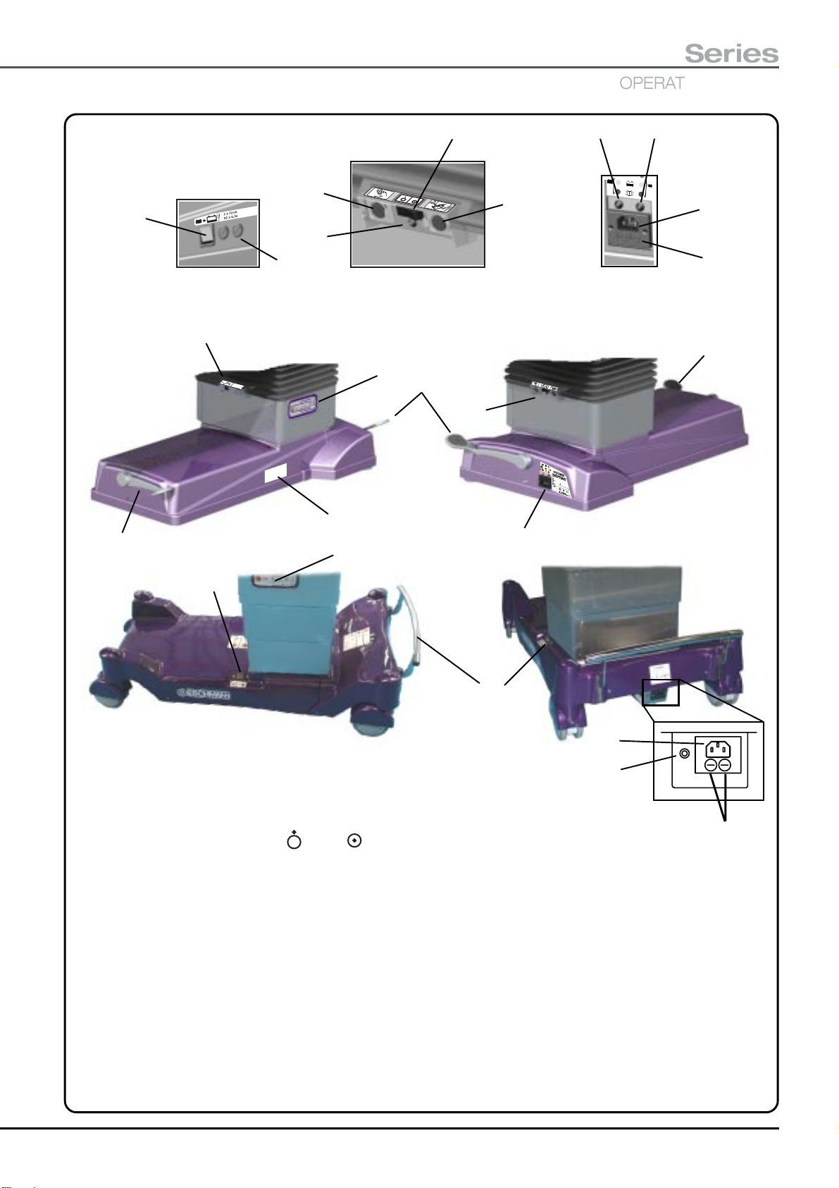
Detail A Detail B Detail C
3
12
11
B
A
C
12
10
1
15
9
1 Standby battery switch
2 T30-a Table's battery fuses
3 Connection socket for Eschmann handset (ONLY)
4 Table ‘On’ LED (green). Bright or Dim see section 5.3.1)
5 Table ‘On/Off’ switch (
6 Connection socket for Eschmann footswitch (ONLY)
7 T30-a Table, mains ‘on’ and Main Battery charging state LED. Red, Amber or Green.
8 T30-a Table, mains ‘on’ and Standby Battery charging state LED. Red, Amber or Green.
9 Connection socket for mains (ONLY use Eschmann mains cord supplied)
10 T30-a Table, castor foot pedal
11 T30-a Table, wheel foot pedal
12 Standby control panel
13 T30-a Table, mains fuses
14 T30-m Table, mains ‘on’ and Battery charging state LED. Red, Amber or Green.
15 T30-m Table, foot pedal
16 T30-m Table, mains fuses
= Off, = On)
14
16
Fig. 2.2 Part identification of the T30 Table base and column.
T-IM122b P11/77

3.0 INSTALLATION
3.1 General
3.1.1 In the U.K. the table is delivered un-crated with
the head and leg section fitted. The mattress set is boxed
individually and placed on the trunk sections. The handset,
mains cord and literature are supplied loose. Any
accessories ordered with the table will be packed
individually.
3.1.2 For overseas markets the table is usually packed in
a container with the head and leg section fitted, together
with a boxed mattress set a mains cord and the literature.
The handset is packed within the container in an antistatic
bag. Other accessories are usually packed separately, but
some may be included in the main case and should be
unpacked and stored separately during table installation.
3.1.2 (Export only) Carefully remove the T30 Table
(having first removed any accessories and packing
restraints from within the container) from the packing case
as follows:-
i Remove the walls of the case leaving the table on
the base still in the braked position as packed.
Remove any chocks from the pallet base to enable
later table movement (iv below).
ii Position the ramp provided (in the packing case)
adjacent to the base of the case.
iii Follow the instruction provided in section 5.1 of this
manual and place the table base into the ‘Wheel’
orientation or mode.
iv With at least two people to support the table’s weight,
push it (do not pull it) off of the pallet base and down
the ramp.
v Note that the table should not be wheeled over rough
ground, always use a trolley until a smooth floor area
has been reached.
vi Should it be necessary to lift the operating table refer
to section 3.2 where suitable lifting points and
methods are detailed.
3.1.3 Unpack the mattress set and fit a mattress to
each tabletop section as detailed in section 5.2.10.
3.1.4 Any packaging materials should be recycled or
disposed of in accordance with current legislation.
supplied fitted to the cord is not suitable it should be
replaced with a suitable plug wired as below. If the plug is
a fused type, a 10A fuse must be fitted. The mains supply
cord must always be wired as follows:
Brown internal cord to LIVE
Blue internal cord to NEUTRAL
Green internal cord to Earth
(Note: The T30-a and T30-m Tables are Class II,
Type BF, there is no EARTH connection through to
the table)
3.1.7 T30 Tables are powered by internal rechargeable
batteries which are connected and charged before delivery.
An internal mains powered battery charger is incorporated
in the table’s base. The table batteries should be recharged
(see section 5.3.1) and the table operated through the cycle
of movements detailed below to check and ensure correct
function, before the tables are first used.
Full Trendelenburg / reverse Trendelenburg
Maximum to minimum height
Maximum tilt, left and right
Maximum to minimum break
CAUTION
To complete and maintain the antistatic
pathway the table must be used on an
electrically conductive or antistatic floor and
with mattresses supplied by Eschmann
Equipment.
3.1.8 The table has an antistatic pathway from the
tabletop, through an internal resistor, to the castors. To
complete the antistatic pathway, the table must be used
on an electrically conductive, or on an antistatic floor (also
see the warning in section 6.1).
3.1.9 As with all medical electrical equipment care
should be taken with regard to electromagnetic
compatibility (EMC) during installation. These instructions
are written in line with the latest international standards
(EN 60601-1-2:2001) and are designed to minimise the
risk of electromagnetic compatibility issues. T30 Tables
should be installed and put into service in accordance with
the EMC information provided in the Technical Data section
of these ‘Instructions for Use’ (Section 9.11).
CAUTION
If the mains plug is changed it is most important
that a fuse of the correct type, size and rating
is used (see Technical Data, section 9.5.4).
3.1.6 T30 Tables require a mains electrical supply
corresponding to the voltage shown on the Serial Number
Plate located on the table base. Only use the Eschmann
mains supply cord provided with the table. If the plug
3.1.10 The table should be cleaned and disinfected prior
to its first use as detailed in section 8.2 and 8.3 and then
commissioned in accordance with any local procedures
applicable to new equipment, this should include staff
training. Eschmann supply a range of wall charts with the
table, additional training aids and on-site training can be
arranged, contact Eschmann [Tel. +44 (0) 1903 765040]
for more information.
P12/77 T-IM122b
T30
OPERATING TABLES
Series
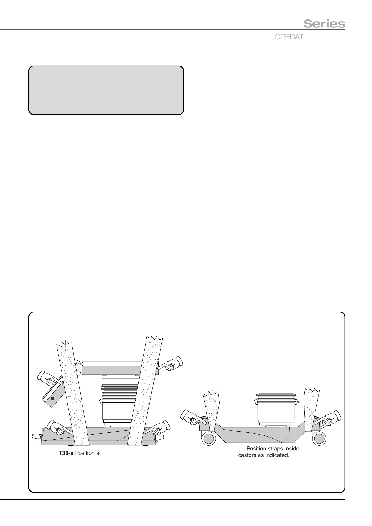
3.2 Lifting the operating table
WARNING
The table is heavy and at least four strong
people are required to lift it. Ensure that
adequate precautions are taken (e.g. wear
protective shoes, use the correct straps).
3.2.1 The T30 Table should only be lifted as a last
resort. Ideally it should be placed on a trolley directly from
the delivery vehicle, or moved on the base of the delivery
packing case (overseas only) and then rolled down the
ramp provided.
3.2.2 If required the T30 Table should only be lifted by
placing suitable webbing straps underneath the table base
in the positions indicated in Fig. 3.1 (having placed the
T30-a Table into its ‘castor’ orientation to increase ground
clearance) and observing the notes that follow.
3.2.3 Extreme care should be taken to pad the straps
where they pass the base covers and the tabletop sections
to avoid damage. Take special care not to cause damage
to the lower edge of the base covers.
3.2.4 Before lifting remove all tabletop sections,
accessories and mattresses, to minimise the weight to
242.7kg* (T30-a Table) or 190.7kg* (T30-m Table). Place
the tabletop into a level plane in both directions
(i.e. tilt and Trendelenburg) as shown in Fig. 3.1. Lower
the short trunk and tabletop to their maximum limits.
*Nominal weight for table with a General Surgical short
trunk, add 14.7kg if an Orthopaedic short trunk is fitted.
3.2.5 The table should only be lifted the minimum
amount required and not carried. Lift the table sufficiently
high to allow a fully decked pallet to be slid underneath.
3.2.6 When lowering the table after the lift take care
not trap feet under the table’s base. The table should be
placed into its ‘braked’ orientation whilst on the pallet.
3.2.7 Transport the table on the pallet using a forklift
truck or similar equipment ensuring the table is strapped
securely to the pallet.
3.2.8 Inspect the table for any signs of damage and
check all functions prior to placing the table into service.
3.3 Technical
3.3.1 The following sections are provided for the user
to note prior to using a T30 Table.
3.3.2 The T30 Table meets the requirements of international standards (see section 9.8) and conform
dimensionally to meet most requirements, for the full table
technical specification details refer to the Technical Data,
section 9.0.
3.3.3 The T30 Table should only be used on an antistatic floor and is classified as type ‘BF’ (i.e. the table has
isolation from earth equivalent to that of type ‘BF’ equipment
when the mains cord is attached).
3.3.4 The antistatic properties of the table depend upon
the use of the recommended mattresses (i.e. Eschmann
antistatic mattresses ONLY) also see section 3.1.8.
Use webbing straps of minimum width 100mm
and a minimum breaking load of 1000kg.
Position adequate padding in the areas indicated
(on both sides) to avoid damaging the table covers.
T30-a Position straps inside, but as
close as possible to the castors.
T30-m Position straps inside
castors as indicated.
Fig. 3.1 Lifting the T30 Table
T-IM122b P13/77

3.3.5 Only Eschmann accessories listed in this manual
should be used on the table and in accordance with the
‘User Handbook’ supplied with the accessory. Accessories
available from Eschmann are listed in section 7.0 and
Appendix 9 (for Orthopaedic accessories). Other
accessories, especially those that could compromise table
stability, must not be used. Use of other equipment with
T30 Tables should only be considered after evaluating the
safety of the patient and personnel. For accessories that
fit onto the sidebar ensure that they are compatible with
the sidebar fitted to the table. These tables can be supplied
with standard UK, Euro USA or Denyer style sidebars, see
section 1.1.2
3.3.6 Provision of a diagnostic port within the table
enables access for reprogramming the table’s software,
down-loading of fault information and service functions.
Use of this port MUST be limited to trained service
personnel only, and should only be used in accordance
with the correct Eschmann manuals (see 3.3.9 below).
3.3.7 The table has four fuses (two on the T30-m) that
the user has access to in the event of failure. The position
of these are shown in Fig. 2.2 and are replaced as detailed
in section 5.3.5.
3.3.8 Eschmann can provide customers with manuals
(see 3.3.9 below), for use by them in maintaining their own
equipment. These manuals contain schematic diagrams,
component part lists, descriptions and calibration
instructions which will assist the customer’s Eschmann
trained personnel to service the equipment or replace parts
(which should only be obtained from Eschmann).
3.3.9 The following manuals are applicable to the T30
Tables and their accessories (the part number is in brackets
following the manual reference) they are available to order,
see inside front cover for contact details:-
T-SM54 (113389) - Service manual
T-IPL41 (113390) - Illustrated parts list
T-IM94 (111012) - Application software manual
T-IM56 (698907) - General accessory leaflet
Note: Some accessories are provided with their
own ‘User/Service Handbooks’.
3.3.10 Appendix 1 provides a log that can be used to
record those people trained in the safe use of this operating
table. It is suggested that this is used to ensure that ALL
personnel using this table, are aware of all the warnings
and cautions contained within these ‘Instructions for use’.
3.3.11 The T30 Tables and their accessories, as listed
in these ‘Instructions for use’, do not contain ‘Latex’.
P14/77 T-IM122b
4.0 SAFETY NOTES & CAUTIONS
4.1 Warnings
Ensure you are familiar with all the warnings and cautions
provided within these ‘Instructions for use’ before using
the table.
T30
OPERATING TABLES
Series
WARNINGS
T30 Tables have been designed to minimise the
possibility of accidental electrosurgery burns.
Contact with any metal surfaces (e.g. table
sidebar, or other equipment etc.) can cause burns
during electrosurgery and must be avoided.
T30 Tables are not rated as AP or APG and should
not therefore be used in the presence of explosive
gases.
T30 Tables have been designed for patients
weighing up to 300kg (47 stone) with their centre
of gravity (normally the umbilicus) positioned
close to the column on the trunk sections.
However patient positioning and additional loads
from accessories can compromise table stability
and strength. Refer to the graphs in section 6.4
for safe loading.
To comply with BS EN 60601-1:1990 some
accessories have been designed for a maximum
evenly distributed load, see the ‘User Handbook’
supplied with each accessory.
With the table in (or during transition into) the
‘castor’ or ‘wheel’ orientation, the centre of
gravity of the patient (normally the umbilicus)
should lie no more than 200mm away from the
centre of the column. Whenever this is not
practical the table should be adequately
supported (e.g. by at least two able people).
The head and leg sections are designed to
support and position the corresponding part of
the patient’s weight only. Damage leading to
failure of the section may be caused if excessive
weight is applied. Take care when handling these
sections to avoid strain and ensure no body parts
or objects are trapped when replacing or
adjusting them.
Only use Eschmann accessories and sections
that are compatible with this table. When parts
are replaced during maintenance procedures,
ensure that ONLY parts supplied by, or from,
Eschmann Equipment are used. Alternatives,
although similar, may affect the safety of the
table. Eschmann cannot be held responsible for
service, modification or adjustments to the
equipment, when performed by other than
Eschmann accredited personnel.
Illustrations and descriptions of patient
positioning are for guidance only. It is the
responsibility of the operating surgeon to make
sure the patient is positioned correctly for each
procedure. (See section 6.0).
During any table positioning procedure care
should be taken to ensure the patient’s safety.
In particular during Trendelenburg and tilt
movements the patient should be supported to
ensure they remain secure on the tabletop. The
patient’s weight should be supported whenever
the sections are adjusted or removed from the
table during repositioning.
During ANY movement of the table or tabletop,
ensure that no part of either patient or hospital staff,
or object (e.g. drapes, infusion tubing, diathermy
connections, ECG cords etc.) can become trapped
between any moving and/or stationary equipment,
or in a pinch point, causing injury or damage to
equipment. Particular table movements that should
be operated with care are reducing the height and
Trendelenburg, which can cause trapping
situations. Always ensure adequate slack is
available in drapes and tubing for the movement
required (e.g. maximum Trendelenburg).
When pushing the table with a patient (maximum
weight 135kg for T30-a or 200kg for T30-m , see
section 5.1) always ensure that the patient’s limbs
are secure on the tabletop to prevent crushing
or trapping them against another object, always
use cot sides (available as an accessory).
Always keep the patient under observation (e.g.
check respiratory and circulatory system and for
the possibility of pressure sores etc.) and
correctly positioned whilst on the table.
Ensure that electrical equipment connected to the
communication port (available during
maintenance procedures only) complies with
appropriate electrical safety standards. Note that
standards compliance of this product may be
affected if noncompliant equipment is attached
to the communication port.
Do not use any table or accessory if there are
visible signs of damage or wear and tear that
could compromise safety.
T-IM122b P15/77

CAUTIONS
Do not place either heavy accessories, or, long
accessories that could impose high torques,
to the sidebars, as this may lead to damage of
the rails.
Do not exceed the duty cycle for any table
motor drive as detailed in the technical data
section 9.5.5.
Care should be taken moving the table over soft
floors (e.g. carpet or ‘cushion’ flooring) as these
will increase resistance to movement
compared to normal hospital ‘hard’ flooring.
4.2 Do’s and Don’ts
Attention to the following points will prolong the life and
efficiency of the T30 Table and will help to avoid the risk of
accidents, or damage. Other safety notes and warnings
are also given within the text of this manual and these
should be noted during use of the table.
DO:
♦ Keep these ‘Instructions for use’ close-to-hand.
♦ Read these ‘Instructions for use’ carefully before
adjusting, moving or using the table.
♦ Use the table on an antistatic floor to prevent
inadvertent static buildup.
♦ Use only the correct Eschmann mattresses and
accessories that are compatible with the T30 Table as
detailed in these instructions.
♦ Check that handset cables and standby controls are
not damaged before use.
♦ Check that the table and its accessories are not worn
or damaged, or are in any way not suitable for the
intended purpose, before use.
♦ Check that all the sections (e.g. head and leg) and
accessories are secure, and put the table base in the
‘braked’ position before use.
♦ Ensure that all cables are not stretched leading to
disconnection or damage during movement or
readjustment of the operating table or patient.
♦ Remove table accessories and their clamps (in
particular rotary clamps) from sidebars, when they
are not being used.
♦ Read and follow the instructions for cleaning, and for
the care of the table and mattresses.
♦ Switch ‘off’ and disconnect from the mains electrical
supply prior to cleaning and/or disinfecting the table
and when it is not being recharged.
♦ Place the table batteries on charge at the end of every
day or shift (see section 5.3.1)
♦ Ensure that the table and accessories are serviced at
regular intervals (every six months is the
recommended frequency) only by Eschmann trained
personnel.
Arrange service contracts through Eschmann
Equipment [Tel. +44 (0) 1903 765040]
♦ Ensure that only the Eschmann mains cord supplied
with the table is used to connect the table to the mains
supply.
♦ Ensure that only Eschmann supplied parts are used
during part replacement.
DO NOT:
♦ Do not lift the table by its tabletop.
♦ Do not move the table with a patient without cot sides
in place on either side of the tabletop.
♦ Do not push the table over rough surfaces, use a
trolley.
♦ Do not drop the table (or individual sections).
♦ Do not put heavy weights on the table sections,
observe the maximum advised loading.
♦ Do not put sharp objects on, or against, mattresses,
pads, or the radiographic tabletop.
♦ Do not place any objects on the base covers
♦ Do not drop heavy objects onto the radiographic
tabletop or base covers.
♦ Do not spill oil, ether, or other fluids onto the mattresses
or the pads.
♦ Do not pull the table by any of the tabletop sections,
or accessories, always push it.
♦ Do not service this equipment unless you have been
trained by Eschmann.
♦ Do not attempt to fit an infill section to another infill
section or a T20 series table.
4.3 Daily ‘Before use’ test
It is recommended that the following ‘Daily test’ is carried
out before using the table:
i Check batteries and charge if required.
ii Check table responds to the all
handset commands.
iii Check table responds to all Standby
control panel commands.
P16/77 T-IM122b
4.4 Accessories
The accessories available from Eschmann for the T30
Tables are listed in section 7.0 and Appendix 9. Use of
other equipment with T30 Tables should only be considered
after evaluating the safety of the patient and personnel.
Inadvertent use of incorrect accessories could damage the
table and lead to injury. Always ensure that the information
in the ‘Instruction’ or ‘User Handbook’ supplied with the
accessory are complied with and follow all the safety notes
contained within them during use. For accessories that fit
onto the sidebars ensure that they are compatible with the
sidebars fitted to these tables. These tables can be supplied
with standard UK, USA or Denyer style sidebars.
4.5 Manual handling
WARNING
Ensure care is taken when moving adjusting
or lifting any part of the table or patient. Note
the guidelines provided.
T30
OPERATING TABLES
Series
4.5.1 During adjustment or changing the configuration
of the T30 Tables, there are occasions when the user
should be aware of the safe practises to be employed
during manual handling or adjustment of parts of the table.
Appendix 4 provides manual handling advice and the
weights of the heaviest sections and accessories
commonly used. When lifting, carrying or fitting heavy
components it is recommended that care is taken and two
or more people are employed when required.
4.5.2 These ‘Instructions for use’ advise supporting the
weight of the patient during adjustment of any section, this
requires the intervention of several personnel, some
supporting the patient’s limbs and others adjusting the table
sections.
4.5.3 When moving the table note that extra effort is
required to start the table moving, take care not to strain
limbs or back. The table should not be moved when heavily
loaded. Note the warnings and cautions provided. It is good
practice to use two or more people when moving a table.
4.5.4 When changing the orthopaedic short trunk
section the special ‘cart’ is recommended and should
always be used, this is fully detailed in section 5.2.5.
4.5.5 To ensure all the orthopaedic accessories are
stored correctly and are easily accessible for use, the
orthopaedic trolley should be used. This is fully detailed
and illustrated in Appendix 8.
T-IM122b P17/77
5.0 OPERATING THE TABLE
This section has been split into sections as follows:
5.1 Moving/Operating the table base.
5.2 Using the removable sections.
5.3 Using the table’s powered/electrical functions.
Note: Orthopaedic procedures are covered in Appendix 5
onwards.
5.1 Moving/Operating the table base
WARNING
Always push the table (do not pull it) at a
suitable height ensuring that it is stable at all
times (maximum stability will be at minimum
height).
Do not move the table around the theatre with
a patient weighing more than 135kg (T30-a
Table) or 200kg (T30-m Table). Take care not to
collide with personnel or equipment.
Ensure that the patient is adequately supported
and restrained (especially limbs) using cot
sides as appropriate.
Ensure all connections via cord or tube, to the
patient or table, have either been disconnected,
or are only attached to equipment that will move
with the table to avoid inadvertent
disconnection.
T30-a Table only When changing from ‘castor’
or ‘wheel’ orientation, to ‘braked’, ensure no
objects (e.g. cords, tubing etc.) can become
trapped beneath the table base and floor.
If the table is difficult to move, check for objects
under castors and that castors are maintained
and kept clean and free from foreign objects.
orientations does not require battery power, they are
manual operations achieved by using one or both of the
foot pedals on the table base.
The table should always be left in the ‘braked’ orientation
with both pedals in their raised positions. Do not leave the
table with the wheel pedal up and the castor pedal down.
When familiar with this section the label on the table base
serves as a quick reference guide to pedal operation.
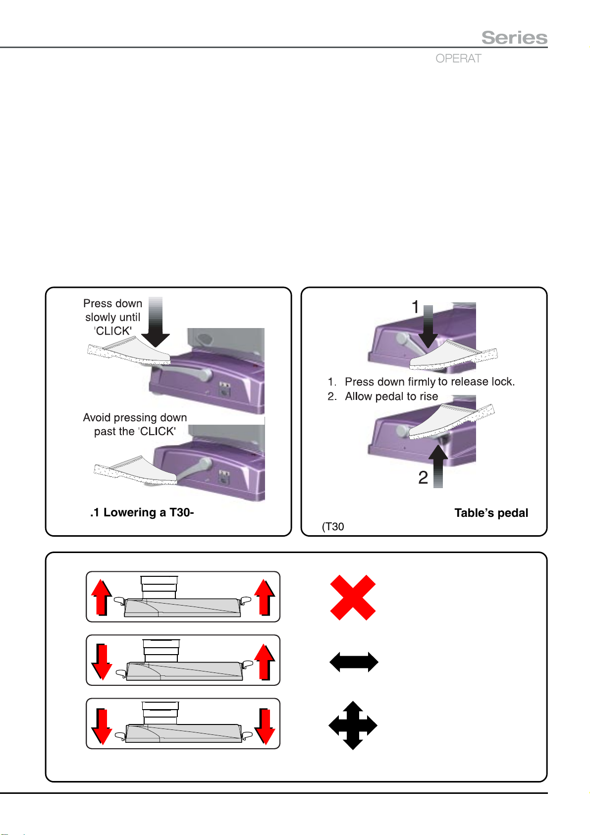
5.1.1.1 ‘Wheel’ orientation (from ‘braked’)
T30-a wheel pedal operation is easily achieved if the pedal
is pressed down with the right foot whilst steadying yourself
with hands on the tabletop. Stand on the side of the table
on which the footpad is located. Use a steady ‘press’ rather
than a ‘rapid depression’ of the pedal.
To place the table into the ‘Wheel’ orientation from the
‘braked’ orientation, press the wheel pedal (shown in
Fig. 5.1) down steadily until you hear an audible ‘click’ (action
indicated in Fig. 5.1). This ‘click’ indicates that the pedal
has locked in the down position. Do not continue to press
the pedal after the ‘click’ as this will release the internal
catch and the pedal will not lock down. If this does happen
the pedal must be allowed to rise fully (this resets the internal
catch) before pressing it down again.
When placed into the ‘Wheel’ orientation the table base is
supported on two wheels at the short trunk end and two
castors at the long trunk end. To move the table in ‘wheel’
orientation always push it (do not pull it) from the long trunk
end, moving the end nearest to you, left or right, to steer the
table in the required direction. The table is in ‘wheel’
orientation when the wheel pedal is in the lowered position
and castor pedal is in the raised position.
5.1.1.2 ‘Castor’ orientation (from ‘wheel’)
T30-a Table's castor pedal operation is easily achieved if
the pedal is pressed with the left foot whilst steadying yourself
with hands on the tabletop. Stand on the side of the table
on which the footpad is located. Use a steady ‘press’ rather
than a ‘rapid depression’ of the pedal.
The T30-a Table has two foot pedals, see section 5.1.1,
the T30-m Table has a single foot pedal, see section 5.1.2.
5.1.1 T30-a Table base
The T30-a Table can be moved easily on built-in castors
and wheels. Normally the table rests on brake pads at the
long trunk end and wheels at the short trunk end, these
provide a secure and static location on the operating theatre
floor. Lower the table to a suitable height to achieve a stable
position before moving the table.
To move the T30-a Table it can be placed onto its wheels
and castors in two ways, providing both a ‘castor’
orientation and a ‘wheel’ orientation. The latter enables
easy movement of the table in a straight line (down a
corridor for example). Moving the table into either of these
To place the table into the ‘castor’ orientation from the ‘wheel’
orientation, press the castor pedal (shown in Fig. 5.2) down
steadily until you hear an audible ‘click’ (action indicated in
Fig. 5.2). This ‘click’ indicates that the pedal has locked in
the down position. Do not continue to press the pedal after
the ‘click’ as this will release the internal catch and the pedal
will not lock down. If this does happen the pedal must be
allowed to rise fully (this resets the internal catch) before
pressing it down again.
When placed into the ‘castor’ orientation the table base is
supported on four castors, two at each end of the table.
This orientation enables the table to be moved in any
direction including sideways and swivelling within its own
length. To move the table always push it in the required
direction, never pull it. The table is in ‘castor’ orientation when
both pedals are in their lowered positions.
P18/77 T-IM122b
T30
OPERATING TABLES
Series
5.1.1.3 ‘Castor’ orientation (from ‘braked’)
To place the table into ‘castor’ orientation from the ‘braked’
orientation follow 5.1.1.1 to place the table into ‘wheel’
orientation and then follow 5.1.1.2 to complete the move
into the ‘castor’ orientation.
Note: It is not critical that sections 5.1.1.1 and 5.1.1.2 are
carried out in this sequence the reverse is equally suitable
and correct.
The table is in ‘castor’ orientation when both pedals are in
their lowered positions.
5.1.1.4 ‘Braked’ orientation
To place the table into the ‘braked’ orientation move both the
pedals into their raised position as follows.
Stand on the side of the table on which the footpad is located
and use the foot advised in 5.1.1.1 or 5.1.1.2 as appropriate.
Steady yourself with your hands on the tabletop. Press the
pedal ‘firmly down’ (action indicated in Fig. 5.2), this
disengages the internal locking catch. Release pressure
on the pedal and allow it to rise. The table will gently lower
into its ‘braked’ orientation, the motion is softened by an
internal damper.
The table is in ‘braked’ orientation when both pedals are in
their raised positions.
Fig. 5.1 Lowering a T30-a Table’s pedal
(T30-a Table’s wheel foot pedal illustrated)
=
=
Fig. 5.2 Raising a T30-a Table’s pedal
(T30-a Table’s castor foot pedal illustrated)
BRAKED
TABLE WILL NOT MOVE
WHEEL
PUSH IN A STRAIGHT LINE
=
Fig. 5.3 T30-a Table’s foot pedal, quick reference guide
T-IM122b P19/77
PUSH IN ANY DIRECTION
CASTOR
5.1.2 T30-m Table base
The T30-m Table base has been provided with four large
castors. The table rests on these castors at all times
providing either a secure and static location on the
operating theatre floor (‘braked’), or two modes for easy
movement (‘castor’ and ‘wheel’ modes).
Adjust the table to a suitable height to achieve a stable
position before moving the table. The T30-m Table should
always be left ‘braked’ with the foot pedal in its lowest
position. When familiar with this section the label on the
table base serves as a quick reference guide to pedal
operation.
Place the table into ‘castor’ mode or ‘wheel’ mode to move
it. The latter enables easy movement of the table in a
straight line (down a corridor for example). The ‘castor’
mode provides full free wheeling mobility with 360° rotation
and sideways movement.
Adjusting the table into either mode does not require battery
power, they are manual operations achieved using the
single foot pedal on the table base (see Fig. 5.4).
5.1.2.1 Foot pedal operation
Foot pedal operation is easily achieved when the pedal is
operated with either foot whilst steadying yourself with your
hands on the tabletop. Stand on either side of the table or
the pedal end, which ever is the most suitable and easy.
Do not operate the pedal from the end of the table when a
long table section (e.g. a leg section) has been fitted to the
long trunk end, this may require unnecessary stretching
by the operator to reach the pedal. Operate the pedal from
the side of the table.
Use a steady motion rather than a ‘rapid’ movement of the
foot pedal, this provides easy identification of the ‘snap’
into any of its three positions.
5.1.2.2 ‘Braked’
To place the table into the ‘braked’ orientation press the
foot pedal (see Fig. 5.4) down to its lowest position. Operate
the pedal as detailed in section 5.1.2.1. and press the foot
pedal down until it snaps into its lowest position.
The pedal can be moved from its highest ‘wheel’ position
through its central ‘castor’ position and into the ‘braked’
position in one easy movement.
The table is ‘braked’ when the foot pedal is in its lowest
position.
The pedal is moved up from its lowest ‘braked’ position by
lifting the pedal up with the top of the foot, or down from its
raised ‘wheel’ position by pressing the pedal down with the
ball of the foot, until the pedal snaps into the central ‘castor’
position.
The table is in ‘castor’ mode when the foot pedal is in its
central position.
Note: When the table has been moved to the required
location always leave the table ‘braked’.
5.1.2.4 ‘Wheel’ mode
WARNING
Do not push the table in the ‘wheel’ mode until
you are sure the castors have moved into their
correct orientation for the ‘wheel’ mode, as
detailed in the second stage below and Fig. 5.4.
If the table is pushed with the castors locked out
of position this will cause undue wear leading to
failure of the short trunk end castors.
Placing the table into the ‘wheel’ mode is a four stage
procedure which will ensure that the short trunk end
castors are locked in position correctly.
First, if the table is ‘braked’ move the foot pedal into its
‘castor’ position as detailed in section 5.1.2.3.
Second, push the table forwards from the long trunk end
until both the short trunk end castors have swivelled into
the position ‘B’ shown in Fig. 5.4. They do not need to be
exactly in line, but they should not be as shown in ‘A’ Fig. 5.4
(i.e. leading their mounts).
Third, lift the pedal up with the top of the foot, as detailed
in section 5.1.2.1, until the pedal snaps into its highest
‘wheel’ position.
Fourth and finally, continue to push the table in a straight
line, the short trunk end castors will lock automatically in
line with the table base. This enables the table to be moved
easily down a corridor, steer from the long trunk end.
The table is in ‘wheel’ mode when the foot pedal is in its
highest position and the short trunk end castors have locked
in-line with the table base.
Note: When the table has been moved to the required
location adjust the table into ‘castor’ mode to enable full
mobility and positioning and then leave the table ‘braked’
(press the pedal fully down).
5.1.2.3 ‘Castor’ mode
To place the table into the ‘castor’ mode, move the foot
pedal (see Fig. 5.4) into its central position. Operate the
pedal as detailed in section 5.1.2.1 and move the foot pedal
until it snaps into its central position.
P20/77 T-IM122b
T30
OPERATING TABLES
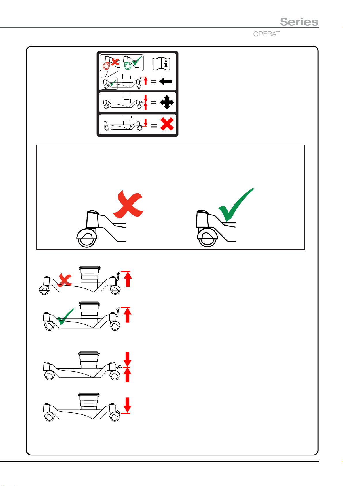
Illustration of the table’s base ‘quick
reference guide’ label. Note the
booklet symbol that indicates
reference to these instructions
should be observed.
113136-01
Detail of the required short trunk end castor postion, which should be obtained, before
lifting the foot pedal into its top position, placing the table base into 'wheel' mode.
Note:
In position A the castor leads its mount, in position B the castor trails its mount.
Series
A
See A above
See B above
B
WHEEL
Select 'castor' mode' (pedal in the central position).
Push the table until the short trunk end castors are
correctly aligned, as indicated. Lift the pedal up fully
into the 'wheel' position (to stop the short trunk end
castors swivelling). This will enable the table to be
'wheeled' in a straight line. Push and steer the table
from the pedal (head) end (see WARNING in section
5.1.2.4).
CASTOR
Lift pedal up, or press pedal down,
into the central position to enable the
table to be 'castored'. All four castors
will swivel allowing full table mobility.
BRAKE
Press pedal down fully with the castors
in any position to brake all four castors.
Fig. 5.4 Operating the T30-m Table base
T-IM122b P21/77
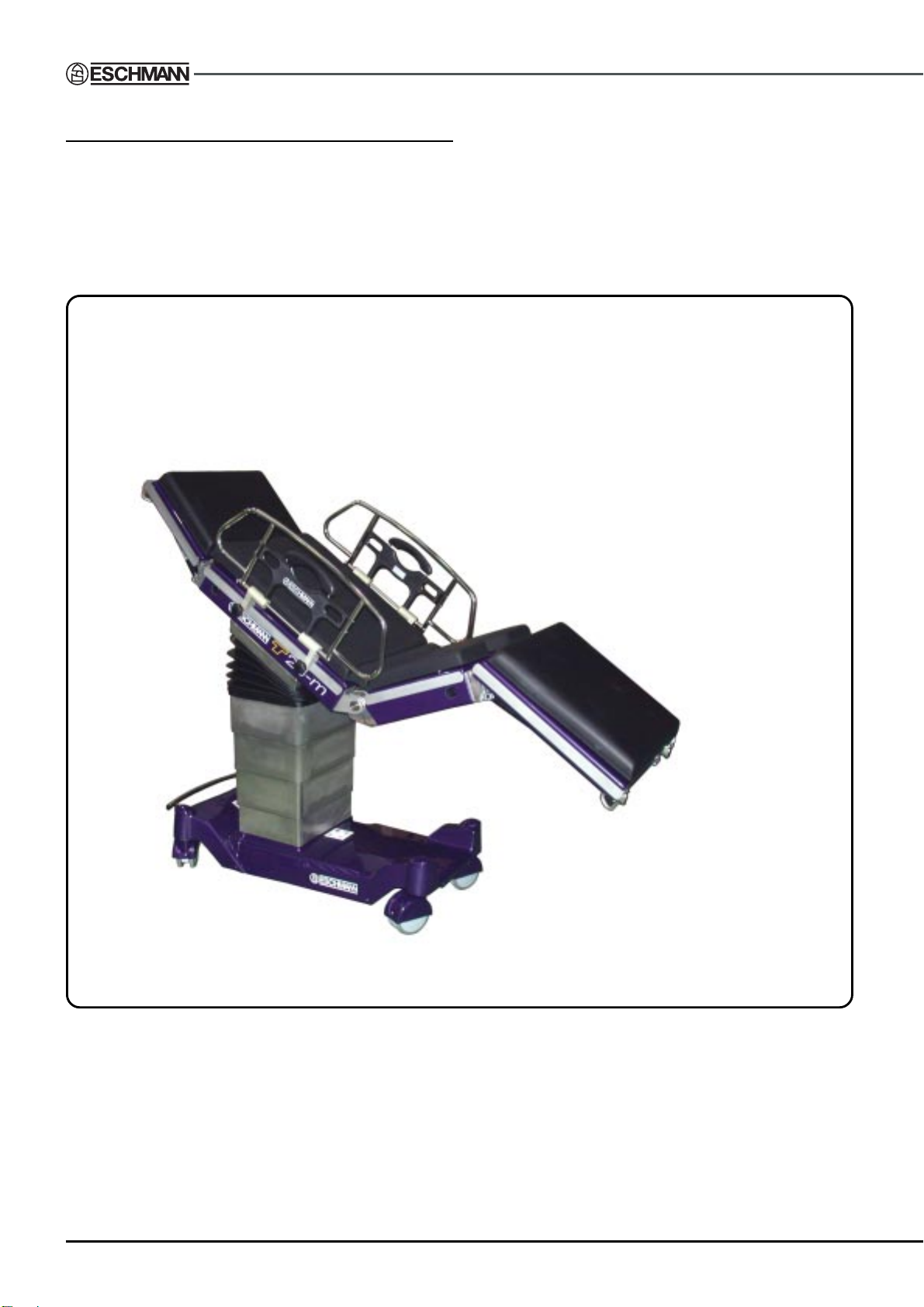
5.1.3 Moving the table with a patient
The normal table position when moving it with a patient is
level in both directions (i.e. tilt and Trendelenburg) and
with the patient in the supine or lateral recovery position.
Fig. 5.5 shows an alternative position that can be used,
the notes in Fig. 5.5 also apply when moving the table with
the patient in the supine or lateral recovery position.
Notes:
Always use cot sides.
Lower table to a suitable height.
Ensure patient limbs are secure.
Check patient weight and position complies with Fig. 6.3.
Always push table from the head end (do not pull).
T20-m table illustrated but position also applies to T30-a and T30-m
tables with or without an infill section fitted to the long or short trunk.
Fig. 5.5 Alternative table position for moving table with a patient
P22/77 T-IM122b

T30
OPERATING TABLES
Series
5.2 Using the removable sections.
All orthopaedic traction accessories and setup procedures
are detailed in Appendix 5 onwards, this section only details
use of the head, leg, infill, short trunk, hip and pre-operative
leg sections. Appendix 8 details use of the accessory trolley
for storing all sections and orthopaedic accessories.
WARNING
Ensure that nothing becomes trapped
(e.g. fingers, tubing, cords) when attaching
tabletop sections. Do not operate the release
bar when a head or leg section is removed from
the table.
When removing a section be prepared to
support the full weight of the section when the
guide pins disengage. Always carry the section
holding the sidebars. Never hold or pick the
section up using the black gas support struts.
Take care not to operate the release bar
accidentally.
When changing the orthopaedic short trunk
section the orthopaedic docking cart should
be used.
5.2.1 Realigning a section’s pins
Realignment of a head or leg section’s pins is only required
if they have become misaligned whilst the section has been
removed from the table (see Fig. 5.6 for illustration of
aligned and misaligned pins).
WARNING
Take care when realigning a sections pins. Ensure
that fingers are clear of the gas springs during
actuation of the release bar.
To realign the pins of a head or leg section place the section
on its side (see Fig. 5.6). Support it by its upper sidebar
only keeping fingers etc. well clear of the gas springs (1,
Fig. 5.6). Actuate the release bar ( 2, Fig. 5.6) until the gas
springs have moved both pins to the ends of their travel,
as shown (3, Fig. 5.6).
To attach the section to a table after realigning the pins
insert the pins into the tabletop for 90% of their length,
actuate the release bar and adjust the section until
horizontal and then push the section fully home until the
locking catches engage (also see section 5.2.2).
For users of small stature, when handling
heavy sections (e.g. the leg section and general
surgical short trunk) two people should work
together to avoid strain injuries.
Before handling a section, minimise the weight
by removing any attached accessory, mattress
or component. Use the ‘cart’ when changing
the orthopaedic short trunk section.
Users of earlier Eschmann tables (e.g. MR and
RX Series) should note that T30 guide pins are
shorter and disengage earlier.
Always ensure that the sections have been
correctly and securely fitted before use and
only use the correct Eschmann sections.
Take care not to actuate the release bar of the head or
legs sections when removed from the table, this may alter
alignment of their pins. Should this happen inadvertently
see section 5.2.1 to realign the pins. For storage and to
aid manual handling (e.g. during table configuration) use
of the orthopaedic accessory trolley is recommended (see
Appendix 8).
The infill section can be attached to the general surgical
short or long trunk sections. The head and leg sections
can be attached to either the general surgical short or long
trunk section or into the infill section. Never attempt to
attach two infill sections together and never remove an
infill section with a leg or head section still attached.
Fig. 5.6 Section pin alignment
5.2.2 Attaching a head, leg or infill section
When attaching a head or leg section first check to see if
the pins are aligned with each other. It is possible that during
storage the release bar may have been actuated and the
pins are no longer aligned as shown in Fig. 5.6. If they are
aligned attach the section as detailed overleaf, if they are
not, align them and attach the section as detailed in section
5.2.1.
T-IM122b P23/77
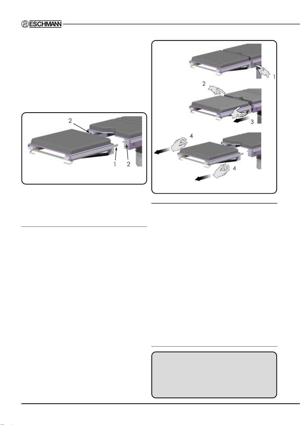
To attach the removable tabletop sections (i.e. head, leg or
infill) hold the section firmly with two hands, aligning the
pins of the section (item 1, Fig. 5.7) with the location holes
(item 2, Fig. 5.7) in the fixed tabletop section as shown in
Fig. 5.7. Do not attach an infill section to another infill section.
Gently insert the section pins into the tabletop and slide
the section into the tabletop evenly until the locking catches
engage with an audible click. The section will slide in easily
if the weight of the section is gently supported with both
hands. Take care not to trap anything (especially fingers)
between the section and the tabletop.
Fig. 5.7 Aligning section pre-attachment
Check that the section is fully inserted and the safety catches
have engaged by gently pulling on the section. Release
buttons (item 9, Fig. 2.1) should be out when the section has
been correctly located and locked.
5.2.3 Removing a head, leg or infill section
When removing a head or leg section ensure that it is
horizontal before removal as this will aid later replacement
(pins will be aligned with the section). If the section is not
horizontal adjust it to horizontal before removal (see section
5.2.4). Do not attempt to remove the infill section with a
head or leg section attached (interlocks inhibit this).
Remove the section from the tabletop by supporting the
section’s weight and pressing in the right-hand section
button (viewed from end of table) as indicated by 1 in
Fig. 5.8. The button will stay in when pressed correctly.
Press in and hold in the left-hand section button (viewed
from end of table) as indicated by 2 in Fig. 5.8 whilst pulling
the section evenly away from the fixed section about 2 3cm (see 3, Fig. 5.8). When employing two people one
should press the button whilst the other pulls the section
out 2 - 3cm. Gently supporting the weight of the section (i.e.
slightly lifting whilst pulling) will make this action easier. Then
release the left-hand section button.
Now using both hands (one on each side of the section as
shown in 4 of Fig. 5.8) continue to gently pull the section
out evenly from the trunk section until the guide pins are
free. Again gently lifting and supporting the weight of the
section will make this action easier. When employing two
people, one should hold the second button in whilst the
other pulls the section out evenly, both can then support
the weight when the pins are free.
Fig. 5.8 Removing a table section
5.2.4 Head and leg section adjustment
The head and leg sections are operated in the same way.
The section’s weight is supported during adjustment and
held locked in position by two gas springs (items 10 and
15, Fig. 2.1). Lowering the section’s release handle during
adjustment automatically locks the section in place.
To adjust either section (having noted the warnings at the
beginning of section 5.2) grasp the end of the section on
both sides with thumbs up and the finger tips resting on
the release bar (items 14 or 16, Fig. 2.1) underneath the
section. Whilst supporting the section in place (it may move
when the release bar is raised), gently lift the release bar
with the finger tips until the section is free to move up or
down (see 1, Fig. 5.9).
When raising the section the gas springs will assist movement, when lowering gentle pressure may be required to
overcome slight resistance of the gas springs. Adjust the
section by rotating it up or down to the required position
(see 2, Fig. 5.9). When the correct position has been
obtained lower the release bar. The section is now locked
in place automatically by the gas springs (see 3, Fig. 5.9).
5.2.5 Changing the short trunk section
WARNING
Always leave a short trunk section attached to
the table to protect the powered stubs indicated
in Fig. 5.11. Do not use the trunk section as a
seat when positioned on the docking cart. Use
two people when handling the sections manually.
P24/77 T-IM122b

Infill section fitted to
long trunk section
T30
OPERATING TABLES
General surgical short
trunk section
General surgical short trunk
section release catches
Orthopaedic short trunk
(with hip sections fitted)
Hip section
Series
Fig. 5.9 Adjusting a head or leg section
WARNING
Always check the short trunk section is
correctly attached. This is indicated on the
section’s label and detailed in the following text.
The short trunk section can be changed to suit the
procedure. Either a general surgical short trunk or an
orthopaedic short trunk section can be fitted, see Fig. 5.10.
The orthopaedic short trunk is heavy and use of the
special orthopaedic docking cart is recommended and
should be used when changing it, see sections 5.2.5.1
- 5.2.5.3. If the cart is not used two people will be required
to change the orthopaedic short trunk see section 5.2.5.4.
Take care not to trap anything between the section and
the tabletop (especially fingers, tubing, cords and drapes).
5.2.5.1 Table preparation for changing short trunk
Before changing the short trunk section ensure ALL
attached accessories have been removed from the long
and short trunk sections, this includes anything attached
to the sidebars, the long and short trunk mattress, the head,
leg, pre-operative leg and any other orthopaedic section
including the removable hip sections, traction beams and
intermediate knuckles. Store applicable accessories on the
accessory trolley (see Appendix 8). Ensure the trolley
and docking cart are clear of the table before
proceeding.
Level the tabletop (press and hold the auto-level button)
then lower the tabletop to minimum height (press and hold
the height down button). Both knuckles on the orthopaedic
short trunk section should be positioned in line with the
table and locked. The castors under the short trunk section
Fig. 5.10 Trunk, infill and hip sections
Powered stubs
Guides
Castors in-line
under covers
Fig. 5.11 Aligning the docking cart to
attach the orthopaedic short trunk.
on the T30-m should be positioned in line with the table
and under the covers as shown in Fig. 5.11. The table
should be ‘braked’, both pedals UP on the T30-a or pedal
fully DOWN on the T30-m.
5.2.5.2 General surgical to orthopaedic short trunk
Press and hold the two release catches underneath either
side of general surgical short trunk section as indicated in
Fig. 5.10 and withdraw the general surgical short trunk
section from the table. Store the general surgical short
trunk section on the accessory trolley, see Appendix 8.
T-IM122b P25/77

Prepare the table to receive the orthopaedic short trunk
as detailed in section 5.2.5.1. Align the docking cart with
the orthopaedic short trunk in place on it, see Fig. 5.11
(also see section 5.2.6). Push the cart towards the table
using the guides for alignment. Push the docking cart firmly
into place as far as possible and check that the orthopaedic
short trunk is fully engaged. Some resistance will be felt
as the docking cart is pushed towards the table and the
short trunk section may lower slightly as it adjusts to the
position of the powered stubs. The red indicators (see
Fig. 5.12) should not be visible (if they are push the cart
and trunk section firmly towards the table).
Hold the docking cart against the table and raise the
tabletop (press and hold the height up button) until the
orthopaedic short trunk section is clear of the docking cart.
Withdraw and store the cart. Check the orthopaedic short
trunk section is securely attached, both catches are down
and the red indicators not visible. Fit the correct trunk
section mattress, accessories and sections as required.
5.2.5.3 Orthopaedic to general surgical short trunk
Prepare the table to change the short trunk as detailed in
section 5.2.5.1. Align the docking cart with the table (using
the guides for alignment) and push it firmly towards the
table until fully engaged with the orthopaedic short trunk
section. Some resistance will be felt as the docking cart
engages with the table and the cart’s docking platform may
be seen to lower slightly as it aligns with the table. Withdraw
the docking cart with the orthopaedic short trunk section
attached, check the section is secure on the cart and store.
Press and hold the two release catches underneath either
side of the applicable short trunk section as indicated in
Fig. 5.10 and withdraw it from the table.
Place the required short trunk section onto the powered
stubs (see Fig. 5.11) and push the section fully home until
the locking catches engage, check the section is securely
attached, both catches are down. The red indicators (see
Fig. 5.12) should not be visible (if they are push the trunk
section firmly towards the table). Fit the trunk section
mattress and accessories as required.
5.2.6 Docking cart preparation
When the orthopaedic short trunk section is not attached
to the table or in place on the docking cart, it can be located
onto the table or docking cart as follows. Attach the
orthopaedic short trunk section to the table using two
Red
indicators
Fig. 5.12 Red indicators on stubs
Place the general surgical short trunk section onto the
powered stubs (see Fig. 5.11). Push the section fully home
until the locking catches have engaged. Check the section
is securely attached, both catches down. The red indicators
(see Fig. 5.12) should not be visible (if they are push the
trunk section firmly towards the table). Fit the correct trunk
section mattress, accessories and sections as required.
5.2.5.4 Changing the orthopaedic trunk section manually
WARNING
The orthopaedic short trunk is heavy, two
people will be required to handle it safely, using
the docking cart is recommended.
Before removing the orthopaedic short trunk section manually
ensure ALL attached accessories have been removed from
it. This includes anything attached to the sidebars, the
mattress, the head, leg, pre-operative leg and any other
orthopaedic section including the removable hip sections,
traction beams and intermediate knuckles. Store applicable
accessories on the accessory trolley (see Appendix 8).
Level the tabletop (press and hold the auto-level button)
and adjust it to a suitable working height. Both knuckles
on the orthopaedic short trunk section should be positioned
in line with the table and tightened. The table base should
be ‘braked’, both pedals UP on the T30-a Table or pedal
fully DOWN on the T30-m Table.
Location slot
Release lever
Fig. 5.13 Parts of the hip section
Location pin hole
(for hips location pin)
Trunk section pin
(for hips location slot)
Fig. 5.14 Attaching a hip section
Location pin
Hold hip section
horizontal
P26/77 T-IM122b

T30
OPERATING TABLES
Series
people (see in section 5.2.5.4). Then to automatically locate
the orthopaedic short trunk section correctly on the docking
cart remove it from the table as detailed in section 5.2.5.3.
5.2.7 Attaching/removing hip sections
Attaching.
left or right). Hold the hip section horizontal (see Fig. 5.14)
and align the location pin of the hip section with the mating
hole in the orthopaedic short trunk. Ensure the location
slot of the hip section slides over the location pin on the
trunk section (see, Fig. 5.13). Continue to push the hip
section in until the release lever (see, Fig. 5.13) engages
and locks the hip section in place. Take care not to trap
anything between the section and the tabletop (especially
fingers, tubing, cords and drapes). Check section is
securely attached.
Removing.
pre-operative leg section or any other removable section
has been removed from the hip section. Then lift the
release lever (see, Fig. 5.13) and slide the hip section
out and away from the orthopaedic short trunk section.
Check you have the correct hip section (i.e.
To remove the hip section first ensure the
5.2.8 Attaching/removing pre-operative legs
Attaching a pre-operative leg section
Hold the pre-operative leg section firmly with two hands
level in both directions and align the single guide pin with
the location hole in a hip section (see, Fig. 5.15). Take
care not to trap anything between the section and the
tabletop (especially fingers, tubing, cords and drapes).
Gently insert the pre-operative leg section’s pin into the
hip section and slide it in evenly until the locking catch
engages with an audible click. The anti-rotation pin (see,
Fig. 5.15) must engage in its location hole before the
section can lock in place. If required slightly rotate the
section about the guide pin to ensure correct orientation
and location of the anti-rotation pin. The section will slide
in easily if the weight of the section is gently supported
with both hands. Check section is securely attached.
Removing a pre-operative leg section
Press in the related hip section release button (see,
Fig. 5.15) and pull the pre-operative leg section out of and
away from the trunk section about 2-3cm. If required at
this stage the pre-operative leg section can be rotated down
about the guide pin and away from the patient. Note: The
right hand hip section button will stay in once pressed.
Release the button and use both hands to pull the preoperative leg section out of and away from the tabletop
trunk section. Although the pre-operative leg section is not
heavy be prepared to support the full weight of the section
when the guide pin disengages. Gently supporting the
weight of the section (i.e. slightly lifting whilst pulling) will
make this action easier.
5.2.9 Changing sections during a procedure
The table sections (except the short trunk) can be changed
during a surgical procedure but extreme care must be taken
to adequately support the patient throughout such
adjustments to the table configuration. Also note the
warning at the beginning of section 5.2.
When replacing a section during a procedure take extreme
care not to trap any part of the patient, surgical drapes,
surgical equipment, cords or tubing. Also note the warnings
in section 4.1.
It is suggested that the mattress is located onto the section
before fitting the section onto the tabletop when
repositioning it during a procedure (allow for the extra
weight).
5.2.10 Attaching/Removing mattresses
Always ensure that mattresses are free from any cuts and
abrasions, such damage can compromise patient safety
by promoting cross contamination. Replace worn
mattresses with new ones as soon as possible.
5.2.10.1 Sections with mushroom pins
These are sections such as the trunk sections, head and
leg sections and divided legs.
WARNING
Guide pin
Anti-rotation pin
Hold pre-operative leg
section horizontal in
both planes
Guide pin location
Fig. 5.15 Attaching a pre-operative
Hip section
release button
Only use Eschmann supplied mattresses and
ensure they are free of cuts and tears, replacing
as required. Do not use without a mattress fitted
to the table.
Do not use any table section or accessory without
the correct Eschmann mattress or pad in place
(except an accessory such as the lightweight leg
section, which can be used for short periods,
without a mattress, during patient positioning).
Mattresses are an important part of the antistatic
pathway and help prevent pressure sores
developing.
leg section
T-IM122b P27/77

Mattresses are attached to these tabletop sections by two
mushroom shaped pins per section. These pins ensure
that the mattress stays in place on the tabletop in all table
configurations. To ensure that the mattress is correctly
located onto the pins proceed as follows:-
i Ensure the mattress is the correct one for the section
you are fitting it to and orientate it relative to the
tabletop so the mushroom pins are lined up with the
mating recesses in the underside of the mattress.
ii Lower the mattress onto the tabletop and gently ease
one location recess at a time onto and over the
respective mushroom pin. The mattress should lie
flat on the tabletop when this has been achieved
without evidence that the pin is holding the mattress
off the tabletop surface.
To remove mattresses reverse the above procedure gently
easing the mattress off the pins, one pin at a time. Ensure
minimal sideways force is applied to the mattress during
this procedure to prolong mattress life.
5.2.10.2 Hip and pre-operative leg sections
The mattresses on these sections are easily changed, but
a hospital engineer will be required. These mattresses have
a rigid integral base and they are screwed onto the section.
The hip section has two M5 x 50mm screws (A, Fig. 5.16)
and the pre-operative leg has six M5 x 12mm screws (B
and C, Fig. 5.16). Access to screws B on the pre-operative
leg section requires removal of the cover plugs. Ensure
the M5 washers used under the screw heads B and C are
replaced and all screws are tightened. If the screw cover
plugs are not secure they should also be replaced.
5.3 Powered and electrical functions.
This section is split into four sections as follows:
5.3.1 Batteries and mains
5.3.2 Powered motions
5.3.3 Using the handset
5.3.4 Using the standby control panel
5.3.5 Changing fuses
Note: Whilst it is safe to use the table when connected to
the mains it is good practice to use the table’s batteries to
power the table, rather than connect the table to the mains.
5.3.1 Batteries and mains
5.3.1.1 Battery charging introduction
WARNING
Ensure that the mains supply used is suitable
(i.e. 100-240V, 50-60Hz) before attaching the
table to the mains supply. Only use the mains
cord supplied with the table and charge the
batteries daily.
CAUTION
Continued use of the table batteries when
‘critically low’ can damage the batteries. Charge
batteries regularly to maintain peak performance.
Do not remove the table from charge until both
charging LED’s are ‘green’ to avoid false battery
level indication on the handset.
B
A
C
Fig. 5.16 Mattress screw location hip
and pre-operative leg
Batteries within the table base are mains rechargeable and
should power the table continuously for 3 days normal use
(from a full charge). However to maintain peak battery
performance the table batteries
charge at the end of each day or shift
should be encouraged as good practice, do not wait for
either ‘low’ battery indication before charging.
Battery charge level is indicated by LEDs on the corded
handset, see Fig. 5.17. The table should be placed on
charge as detailed in section 5.3.1.2. Also see battery
management sheet Appendix 3.
Note: Over the first few charge cycles (from new) battery
capacity increases until they reach a stable maximum level.
Batteries should be checked for adequate charge before
using the table for any surgical procedure. The corded
handset has two battery level indicators, one for the main
battery and one for the standby battery, see Fig. 5.17.
These indicators will only operate when the corded handset
is plugged into the table and the table is switched ‘on’.
Each indicator contains three coloured LEDs, these
indicate the following information.
should be placed on
. Daily charging
P28/77 T-IM122b

T30
OPERATING TABLES
Series
Main battery level indicator:
Green LED ‘on’ = Battery level satisfactory.
Amber LED ‘on’ = Low battery. An indication that
the remaining battery charge is only adequate for
one day’s average use. Batteries MUST be
recharged at the end of the current shift.
Red LED ‘on’ = Critically low battery. An indication
that the remaining battery charge is critically low.
Batteries MUST be recharged as soon as possible
and before the next procedure. Charging during the
current procedure is not recommended.
Standby battery level indicator:
Green LED ‘on’ = Battery level satisfactory.
Amber LED ‘on’ = Low battery. Battery level is low
and only adequate for two or three Trendelenburg
movements, they MUST be recharged at the end of
the current shift.
Red LED ‘on’ = Critically low battery. Battery level is
critically low and only adequate for one Trendelenburg
movement. They MUST be recharged as soon as
possible and before the next procedure. Charging
during the current procedure is not recommended.
Handset (battery charge level)
5.3.1.2 Battery charging
To recharge the table batteries (normal and standby)
connect the mains cord supplied with the table (do not
use any other mains cord) into the mains inlet (item 9,
Fig. 2.2).
Connect the mains cord to a suitable mains supply (check
mains voltage is 100-240V, 50-60Hz) and switch the supply
‘on’ if controlled by a switch.
The battery charging LEDs (items 7 and 8 of Fig. 2.2 for
the T30-a Table, or item 14 for the T30-m Table) will
illuminate ‘red’ to indicate ‘bulk’ recharge, ‘amber’ to
indicate that the batteries are in a 2 hour ‘top-up’ charge
and will illuminate ‘green’ to indicate a fully charged battery
on ‘trickle’ charge (Note. The T30-m Table only has one
LED indicating both main and standby charging state).
The batteries should be fully charged within six hours (if
the table is not in use) but it is safe to leave the mains
supply ‘on’ when the batteries are fully recharged and both
LEDs are ‘green’ (or in the case of the T30-m Table the
single LED is ‘green’). See CAUTION in section 5.3.1.1.
Note: Always ensure the table is switched ‘off’ to minimise
the battery charging time.
It is recommended that the mains cord is stored in the
storage tray of the orthopaedic accessory trolley to avoid
loss and inadvertent use of an incorrect mains cord.
Main
Table (battery charging state)
= 'Trickle' charge
= 'Top-up' charge
= 'Bulk' charge
Standby
Fig. 5.17 Handset and charging indicators
Note T30-m has only one charging LED
indicating the level for both batteries.
When the main battery ‘critically low’ warning is indicated
the table cannot be operated by either handset or the
footswitch. To continue to operate the table either connect
it to a suitable mains supply and recharge the batteries
(see 5.3.1.2) or use the standby batteries (see 5.3.1.4).
Note: The standby control panel can be used even when
the ‘critically low battery’ indication is given but note the
warning in section 5.3.4.
5.3.1.3 Battery changing
Batteries in the table base should only be changed by service
personnel. They should last for many years if recharged
regularly and should not require user intervention (also see
section 8.6.3 for the caution concerning disposal).
5.3.1.4 Standby batteries
WARNING
The standby batteries are for emergency use
only and will only provide power for a few
movements.
The table is provided with standby batteries to cover the
unlikely event of a main battery failure or fault. To use the
standby batteries, the standby battery switch (see item 1,
Fig. 2.2) must be pressed and held depressed whilst the
required motions are conducted using the normal hand
and foot controls.
The standby batteries are only used when the standby
battery switch is depressed and they are automatically
recharged during the normal battery charging process.
T-IM122b P29/77

5.3.2 Powered motions
WARNING
Always ensure that the patient is secure or
adequately supported during all tabletop
adjustments and that such adjustments do not
compromise table stability.
If a patient is on the table and the handset is
clipped onto the tabletop, take care that the
handset buttons are not inadvertently activated
(e.g. by a patient Transporter or person) causing
unwanted table movements.
Similarly take care at all times to ensure that the
handset is not inadvertently activated.
During all tabletop adjustments be aware of
pinch points between the moving and static
parts (e.g. the break hinge and head and leg
hinges).
Ensure that all theatre drapes, electrical cords
and any medical tubing etc. are clear from
entrapment in pinch points and that adequate
excess drape, cord, or tube, are available to cater
for the adjustment required.
Ensure that any motion and adjustment
selected will not cause any part of the table to
hit or collide with any person or object.
Examples being:-
i) Leg section hitting floor when table is low
and reverse Trendelenburg selected.
ii) A fully lowered leg section hitting table base
when tabletop is lowered.
iii) Head section hitting anaesthetist’s seat
when Trendelenburg selected.
CAUTION
Do not exceed the duty cycle for any motor
drive as detailed in section 9.5.5.
5.3.2.1 General
The major tabletop adjustments and motions are powered.
These powered motions are controlled by a corded handset
supplied with the table (see 5.3.3) and the standby control
panel (item 12, Fig. 2.2 see section 5.3.4). An optional
footswitch (see accessory list section 7.0) can also be used
to control the tabletop, use of this footswitch is explained
in the leaflet provided with it.
Powered tabletop motions are, Trendelenburg, height, tilt,
brake, flexion and return to level. Each motion in either
direction is controlled by pressing and holding the
appropriate handset, footswitch or standby control panel
button(s). The table must be switched ‘on’ for powered
motions to operate. Section 5.3.3.2 details handset button
functions, section 5.3.4 provides standby control panel
information.
All signals from controllers will be treated in a strict priority
order to avoid multiple activation errors. Inputs will be
responded to in the sequence below:
1 Standby control panel
2 Corded handset
3 Footswitch control.
Button presses from a controller lower on this list will be
ignored if any button is pressed on a controller higher on
the list and the input from the higher controller will be
actioned.
The table cannot be powered by footswitch, or handset,
when the main battery ‘critically low’ indication is displayed
(see Fig. 5.17, main battery LED is ‘red’) unless the standby
battery switch (item 1, Fig. 2.2) is held depressed. However
the tabletop can be controlled by the standby control panel
(item 12, Fig. 2.2) situated on the side of the column. This
standby control panel has limited functionality in
comparison to the handset and should ONLY be used in
an emergency (e.g. handset or footswitch failure, control
system failure, or ‘critically low’ battery).
Use of this standby control panel in any situation other
than an emergency SHOULD be avoided as certain safety
devices are overridden. The controls and buttons of the
standby control panel are detailed in section 5.3.4. In the
unlikely event of insufficient battery power when using the
standby control panel, press and hold the standby battery
switch (item 1, Fig. 2.2) whilst conducting powered motions.
In the unlikely event of failure of the main table batteries,
‘press and hold’ the standby battery switch (item 1, Fig. 2.2)
in the ‘on’ position and use the corded handset or the
standby control panel to control the table. This enables
the standby batteries to power the table, however the main
battery fault should be rectified as soon as possible.
5.3.2.2 Tabletop motions
WARNING
Ensure you have read and understood the
safety warnings listed in section 4.1 and 5.3.2
before using any of the powered motions.
All powered tabletop movements are programmed to
provide a gentle transition from stationary into the required
motion and back again to stationary (i.e. initially the motion
starts slowly and then speeds up to maximum speed and
then slows again before coming to a stop). This also
enables accurate positioning at slow speed by using
repeated short button presses. Alternatively long duration
button presses allow large changes in tabletop position at
maximum speed.
P30/77 T-IM122b

T30
OPERATING TABLES
Series
To operate the tabletop powered motions the table must
be switched ‘on’ ( ) at the table on/off switch (item 5,
Fig. 2.2). The table will emit a single ‘beep’ and the
green LED (item 4, Fig. 2.2) will illuminate to show the
table is ‘on’. The LED will be bright during use but only
dim if the operating system has gone into ‘sleep’ mode
(saving battery power). The table will instantly respond
to any control input even when in ‘sleep’ mode. Also
see section 8.1.
If two buttons are pressed on a handset or footswitch at
the same time neither will have any effect. The function of
the second button pressed is ignored and automatically
cancels the function of the first button pressed and any
table motion stops. Releasing either of the buttons will
enable the function of the remaining button (if still pressed)
to be actioned. This is to eliminate multiple button activation
errors.
Most powered tabletop motions will pause briefly when they
pass through the level position (Note: not applicable to
height). This is to enable each motion to be returned to a
level position individually.
Be aware that a lowered leg section could hit the table base
when the top is lowered, or the head section could collide
with an anaesthetist’s chair during a Trendelenburg
movement.
Always ensure that there is adequate space around the
table for the movement selected and that the movement
required will not cause injury to patient or medical
personnel. Look for possible trap and or pinch points
between parts of the table and stationary objects.
5.3.3 Using the handset
5.3.3.1 General
WARNING
Do not plug two handsets into the table at the
same time. When two handsets are connected,
neither handset will operate the table.
The corded handset will operate any T30 Table. The corded
handset simply plugs into either of the table handset sockets
(item 3 of Fig. 2.2 and item 2, Fig. 5.18). Never plug handsets
into both sockets at the same time. See section 5.3.3.2 for
details of button function and section 5.3.1.1 for an
explanation of the battery state LEDs.
When using the corded handset always ensure that the cord
is well clear of any moving parts, pinch points and possible
entrapment from table movements. Also ensure that the cord
will cater for any table movement and that such table
movements do not stretch the cord excessively.
When not in use it is suggested the handset is clipped onto
the accessory sidebar (item 12, Fig. 2.1). Note that when
clipped onto the table in this way it can be operated with
one finger, without the need to hold it in the other hand. The
handset must be compatible with the sidebar fitted to the
table, see sections 1.1.2. The UK handset will also clip onto
head/leg end blocks (item 13, Fig. 2.1).
To remove the handset plug from its socket the release
button (item 1, Fig. 5.18) must be pressed and held in during
removal. When removing the corded handset plug from its
socket always grip and pull the plug, do not pull the cord
only as this may damage the cord or internal connections.
Handset buttons provide a tactile feedback to enable the
user to detect when a button has been pressed or released,
this is in the form of a ‘pop’ or ‘click’. Also, all buttons are
‘de-bounced’ to ensure that only deliberate button presses
are responded to (i.e. an accidental quick activation is
ignored).
Fig. 5.18 Controller sockets and
release buttons
5.3.3.2 Handset button functions
Handset buttons have their function indicated by graphics
printed on the handset, see Fig. 5.19.
To activate the required tabletop motion press and hold
the appropriate button until the required amount of change
in tabletop position has been achieved, then release the
button. The actual motion for each button is fully detailed
below, refer to Fig. 5.19 for button reference.
Note: Buttons B1 and B2 provide the described movement
for a tabletop in the normal orientation (head section in
long trunk) with the patient’s head on the head section. If
the patient orientation is reversed button functions B1 and
B2 are also reversed.
B1 Trendelenburg (orange button). Press to
rotate the tabletop in the Trendelenburg
(head down) direction.
B2 Reverse Trendelenburg (orange button).
Press to rotate the tabletop in the
Reverse Trendelenburg (head up)
direction.
B3 Height down. Press to lower the whole
tabletop.
B4 Height up. Press to raise the whole
tabletop.
T-IM122b P31/77

T30-a Table Serial label (end of table base)
Handset Serial label (on back)
T30-m Table Serial label (on trunk section)
SN T20A1JI090
REF T20-1-3-1101
2005-08
Fig. 5.19 Handset button functions and serial labels
(labels are examples only and text on actual table will be different to that shown above)
P32/77 T-IM122b

T30
OPERATING TABLES
Series
B5 Tilt left - Press to tilt the whole tabletop
down on the left-hand side when viewed
from the long trunk end.
B6 Tilt right - Press to tilt the whole tabletop
down on the right-hand side when viewed
from long trunk end.
B7 Break down - Press to move the tabletop
in the break down (Extension) direction.
B8 Break up - Press to move the tabletop in
the break up (Flexion) direction.
B9 Extension - Press to move table into
Extension.
B10 Flexion - Press to move table into
Flexion.
B11 Return to Level - Press to return the
tabletop to a ‘preset’ level position.
This may invoke all powered
movements to achieve the ‘preset’
level position. The sequence of movements is tilt then
Trendelenburg and Break together. (Note: Height is
not affected).
Tilt, Trendelenburg and Break motions will pause
momentarily when passing through a ‘level’ position.
Note that ‘Break’ is level when the trunk sections are inline with each other, they will not be horizontal unless
Trendelenburg is horizontal.
5.3.4 Using the standby control panel
WARNING
The standby control panel MUST be used with
extreme care for Trendelenburg movements. All
programmed safety features are overridden in
this mode (e.g. should the tabletop hit an
object, motor protection is inhibited and
damage to them could occur). Also do not
exceed 30° of Trendelenburg (or reverse) from
the standby panel.
The standby control panel is located on the side of the
column (item 12, Fig. 2.2). The panel has five function
buttons (OB1 to OB5, see Fig. 5.20) and two direction
buttons (OB6 and OB7, see Fig. 5.20). The motion of the
function button is described by its graphical symbol
(symbols are shown and detailed in section 2.2.4).
When controlling the tabletop from this standby control
panel certain inbuilt safety features are overridden. Also
there is no ‘soft start’ to the powered Trendelenburg
movements and the tabletop will not pause as it passes
through the level (Trendelenburg) position. Only four
functions can be controlled from this panel Trendelenburg,
Height, Tilt and Break, traverse is not applicable to T30
Tables.
Fig. 5.20 Standby control panel
To operate the tabletop from this panel select a required
function by ‘pressing and holding’ a function button
(i.e. OB1 to OB4, Fig. 5.20) and then select a direction for
this function by ‘pressing and holding’ a direction button
(i.e. OB6 or OB7, Fig. 5.20).
Pressing the upper or lower direction button will select the
direction indicated by the corresponding arrow on the
function button. The table will move whilst both the function
button and the direction button are pressed, releasing either
will stop the motion. Motions for each button are fully
detailed in the following sections.
OB1 Trendelenburg - Press and hold this button,
then press required direction button to rotate the
tabletop in the Trendelenburg (button OB6,
Fig. 5.20) or reverse Trendelenburg direction
(button OB7, Fig. 5.20)
OB2 Height - Press and hold this button, then press
required direction button to change the height of the
tabletop (button OB6, Fig. 5.20 is for Height up;
button OB7, Fig. 5.20 is for Height down).
OB3 Tilt - Press and hold this button, then press
the required direction button to tilt the tabletop
(button OB6, Fig. 5.20 is for Tilt down on the left;
button OB7, Fig. 5.20 is for Tilt down on the right,
when viewed from the long trunk end of the table).
OB4 Break - Press and hold this button, then press
required direction button to move the tabletop in the
Break up or Flexion direction (button OB6, Fig. 5.20)
or Break down or Extension direction (button OB7,
Fig. 5.20).
OB5 Traverse - Non functional Button. This button
selects a Traverse function on other tables in the ‘T’
series.
T-IM122b P33/77

5.3.5 Fuse replacement
The fuses are located as shown in Fig. 2.2 items 2 and 13
for the T30-a Table and item 16 for the T30-m Table. Fuses
adjacent to the mains inlet socket are only applicable to
the mains supply for the battery charger. Fuses in the side
of the table base adjacent to standby battery switch (T30-a
Table ONLY) are applicable to the main batteries and
standby batteries.
These fuses are replaced as follows:-
i Remove the mains cord from the table before
replacing any of the fuses and switch the table ‘off’
with switch item 5, Fig. 2.2.
ii Turn the fuse cover cap anticlockwise to remove
the cap with the fuse inside.
iii Ensure you have the correct fuse (consult the
markings adjacent to the fuse or the Technical Data,
section 9.0).
iv Place the new fuse into the cap and replace the cap
by screwing it in clockwise.
P34/77 T-IM122b
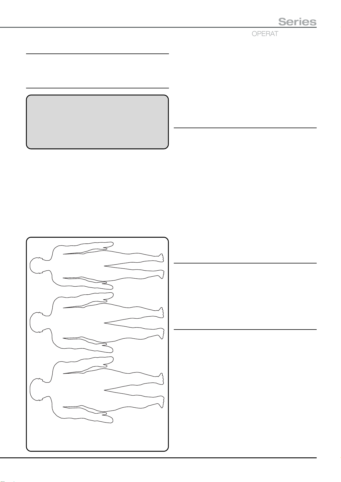
T30
OPERATING TABLES
Series
6.0 PATIENT POSITIONING
Note: Orthopaedic positioning, accessories and
procedures are all covered in Appendix 5 - 10.
6.1 General
WARNING
Do not use any table section or accessory without
the correct Eschmann mattress or pad in place
(also see section 5.2.10). Mattresses are an
important part of the antistatic pathway and help
prevent pressure sores developing.
Ensure the patient’s weight is evenly distributed and that
the mattress or pad is correctly positioned on each section
of the table. Check at frequent intervals during long
procedures to ensure that pressure sores are not being
promoted. See section 5.2.10 for details on attaching and
removing mattresses and Appendix 5 - 10 for orthopaedic
positioning, accessories and procedures
Note the graphics in section 6.4 which provide maximum
loading details for various table positions. The normal
maximum loading, for the patient’s centre of gravity (C of G)
135kg
10
200kg
15
5
5
8
8
11
300kg
22
11
Fig. 6.1 Approximate patient weight
5
15
55
15
5
7
22
81
22
7
11
33
124
33
11
distributions
10
10
15
15
22
22
in various positions is shown in Figs. 6.3 and 6.4. For
guidance on the treatment of the obese patient, see
section 6.2.
The Figures in section 6.4 provide details of various patient
positions that can be arranged with the T30 Table. Note
that these illustrations are examples only and care should
be taken to ensure patient safety and table stability.
Section 6.5 shows pictures covering the various tabletop
configurations.
6.2 Treatment of the obese patient
Always ensure that the table is correctly loaded to maintain
stability within the guidelines shown in the graphs of section
6.4 noting the maximum patient weight for the top in use
(i.e. 300kg). Note that the centre of gravity for the maximum
patient weight of must not be outside of the top plateaux
section of the graphs.
Width extenders can be placed on either side of the table to
help support the patient but note the maximum load for this
accessory and that width extenders should not be attached
to each other (also see Warnings and Cautions in the width
extenders ‘User Handbook’ ).
The table should not be moved across the floor with a
patient weight over 135kg (T30-a Table) or 200kg (T30-m
Table). Although it is possible to place the T30-a Table into
‘castor’ or ‘wheel’ with a patient over 135kg and up to 300kg
this is not advised.
6.3 Radiographic procedures
All ‘C-arm’ image intensifiers are suitable for use with this
table. Fig. 6.2 shows typical patient positions for imaging
the upper and lower torso with the patient in the Supine
position on the general surgical top. The graphics would
equally apply to patients in the Prone position. See
Appendix 10 for radiographic procedures during
orthopaedic procedures.
6.4 Table positions and safe loading
In Figures 6.5 to 6.10, common table and patient positions
and safe loading graphs are provided, to give guidance on
patient positioning and table loading. Because it would not
be possible to cover every situation these should be
considered as examples only. Refer to Figs. 6.5 to 6.10
and then use Figs. 6.3 and 6.4 to establish the maximum
patient weight allowed for that configuration. The weight of
additional accessories fitted to the table should be included
in any estimation of correctly applied loads.
Figs. 6.3 and 6.4 show graphs of the position of the
maximum patient weights (centre of gravity) that can be
positioned on the table in four table configurations. Because
all variations can not be covered, a degree of interpolation
is required by the user, to ensure that table stability is
maintained. Fig. 6.1 provides an approximate patient
weight distribution for guidance.
T-IM122b P35/77

Patient positioning for maximum ‘C’ arm imaging of the required area (General surgical top).
Additionally there is an X-ray cassette tunnel, accessible from either end.
Table in general surgery configuration with
infill section fitted into standard short trunk
Lower torso imaging
Patient in normal orientation with table
head and leg sections in the normal
position with the infill section fitted into the
general surgical short trunk. Patient
positioned down the table to maximize the
amount of lower torso in the imaging area.
Table in general surgery configuration
with infill section fitted into long trunk,
head and leg sections reversed
NOTE: All illustrations are
examples only. Care should be
taken in patient positioning to
ensure stability, see section 6.3.
For the obese patient see section
6.1.
Upper torso imaging
Patient in normal orientation with table
head and leg sections reversed from their
normal position (i.e. leg section in the
long trunk) and with the infill section fitted
into the long trunk. Patient positioned up
the table to maximize the amount of
upper torso in the imaging area.
Fig. 6.2 Patient positioning for radiographic procedures
P36/77 T-IM122b

300kg
200kg
100kg
T30
OPERATING TABLES
Series
Infill fitted to short trunk
Leg section in long trunk
300kg
200kg
100kg
Infill fitted to short trunk
Head section in long trunk
300kg
200kg
100kg
These graphs indicate the centre of
gravity (normally the umbilicus) for the
maximum patient weight that can be
placed on the table (when configured as
shown).
To aide interpretation a patient weighing
200kg should be positioned so their
umbilicus lies between the dotted
vertical lines.
The solid graph applies when the
general surgical short trunk section is
fitted, the dotted graph applies when
the orthopaedic short trunksection is
fitted.
Both graphs take into account the infill
section, this being the ‘worst case’
situation.
Infill fitted to long trunk
Head section in long trunk
300kg
200kg
100kg
Infill fitted to long trunk
Leg section in long trunk
Fig. 6.3 Maximum patient weight v table position graphs
(general surgical configurations).
T-IM122b P37/77

300kg
200kg
100kg
This graphs indicate the centre of gravity (normally the umbilicus)
for the maximum patient weight that can be placed on the table
(when configured as shown for orthopaedics).
To aide interpretation a patient weighing 200kg should be
positioned so their umbilicus lies between the dotted vertical lines.
Fig. 6.4 Maximum patient weight v table position graphs
(orthopaedic configuration).
P38/77 T-IM122b

T30
Table in general surgery configuration with
infill section fitted into standard short trunk
Table in general surgery configuration
with infill section fitted into long trunk,
head and leg sections reversed
OPERATING TABLES
Series
Table in general surgery configuration with
infill section fitted into standard short trunk
120kg with the general surgical short trunk fitted
The maximum patient weight, for one in the above position is:
or 110kg with the orthopaedic short trunk fitted
220kg with the general surgical short trunk fitted
The maximum patient weight, for one in the above position is:
or 115kg with the orthopaedic short trunk fitted
170kg with the general surgical short trunk fitted
The maximum patient weight, for one in the above position is:
or 165kg with the orthopaedic short trunk fitted
Table in general surgery configuration
with infill section fitted into long trunk,
head and leg sections reversed
250kg with the general surgical short trunk fitted
The maximum patient weight, for one in the above position is:
or 260kg with the orthopaedic short trunk fitted
Fig. 6.5 Patient in various ‘Supine’ positions
T-IM122b P39/77

Table in general surgery configuration with
Table in general surgery configuration with
infill section fitted into standard short trunk
Table in general surgery configuration
with infill section fitted into long trunk,
head and leg sections reversed
infill section fitted into standard short trunk
170kg with the general surgical short trunk fitted
The maximum patient weight, for one in the above position is:
or 165kg with the orthopaedic short trunk fitted
300kg with the general surgical short trunk fitted
The maximum patient weight, for one in the above position is:
or 300kg with the orthopaedic short trunk fitted
250kg with the general surgical short trunk fitted
The maximum patient weight, for one in the above position is:
or 260kg with the orthopaedic short trunk fitted
170kg with the general surgical short trunk fitted
The maximum patient weight, for one in the above position is:
or 165kg with the orthopaedic short trunk fitted
Table in general surgery configuration
with infill section fitted into long trunk,
head and leg sections reversed
Fig. 6.6 Patient in various ‘Prone’ positions
P40/77 T-IM122b
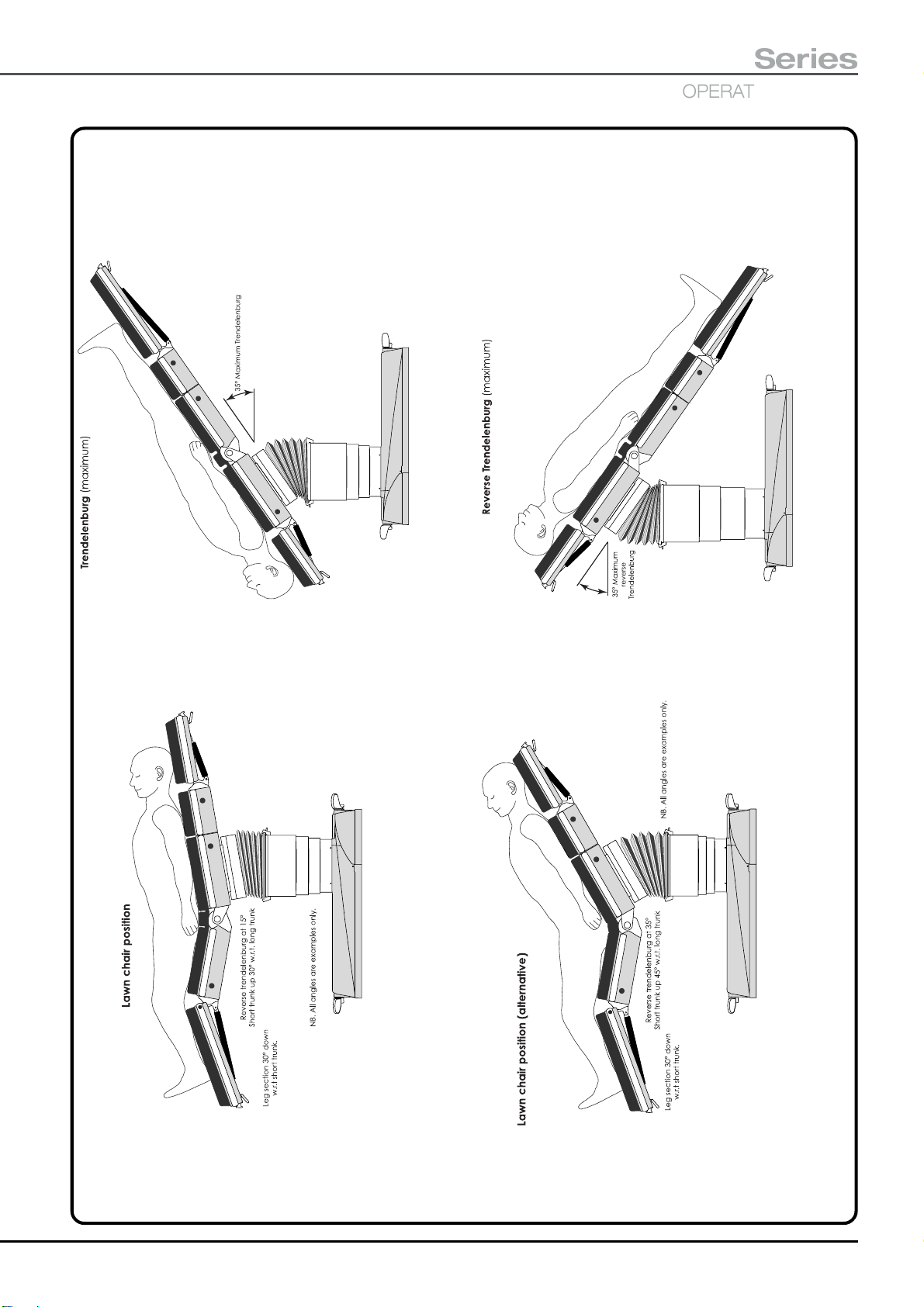
Table in general surgery
configuration with infill section
fitted into standard short trunk
Note warnings in section 2.1
regarding patient support.
Table in general surgery
configuration with infill section
fitted into standard short trunk
T30
OPERATING TABLES
Series
Table in general surgery
configuration with infill
section fitted into long trunk
300kg with the general surgical short trunk fitted
The maximum patient weight, for one in this position is:
or 300kg with the orthopaedic short trunk fitted
Table in general surgery
configuration with infill section
fitted into long trunk
300kg with the general surgical short trunk fitted
The maximum patient weight, for one in this position is:
or 300kg with the orthopaedic short trunk fitted
240kg with the general surgical short trunk fitted
The maximum patient weight, for one in the above position is:
or 235kg with the orthopaedic short trunk fitted
240kg with the general surgical short trunk fitted
The maximum patient weight, for one in the above position is:
or 235kg with the orthopaedic short trunk fitted
Fig. 6.7 Patient in various ‘Lawn chair’ & ‘Trendelenburg’ positions
T-IM122b P41/77

NB. Infill section fitted into long trunk.
The maximum patient weight, for one in the above position is:
300kg with the general surgical short trunk fitted
or 300kg with the orthopaedic short trunk fitted
NB. Infill section fitted
into long trunk.
The maximum patient weight, for one in the above position is:
300kg with the general surgical short trunk fitted
or 300kg with the orthopaedic short trunk fitted
NB. Infill section in short trunk,
head section fitted to infill.
The maximum patient weight, for one in the above position is:
300kg with the general surgical short trunk fitted
or 300kg with the orthopaedic short trunk fitted
The maximum patient weight, for one in the above position is:
300kg with the general surgical short trunk fitted
or 300kg with the orthopaedic short trunk fitted
Fig. 6.8 Patient in various ‘Chair’ positions
P42/77 T-IM122b

with infill section fitted into short trunk
(suitable for lighter patients only)
T30
Series
OPERATING TABLES
The maximum patient weight, for one in this position is:
140kg with the general surgical short trunk fitted
or 130kg with the orthopaedic short trunk fitted
The maximum patient weight, for one in this position is:
100kg with the general surgical short trunk fitted
or 90kg with the orthopaedic short trunk fitted
The maximum patient weight, for one in this position is:
300kg with the general surgical short trunk fitted
or 300kg with the orthopaedic short trunk fitted
Note: Iliac crest support may be
useful to reduce knee damage
for all three positions.
Fig. 6.9 Patient in various ‘Proctology’ positions
T-IM122b P43/77

Shown with and without infill section
fitted in short trunk section.
Note: Positon less stable when infill fitted and
should only be used for the lighter patient.
200kg (or 140kg with infill) with the general surgical short trunk fitted
The maximum patient weight, for one in the above position is:
or 100kg (or 90kg with infill) with the orthopaedic short trunk fitted
Head section in short trunk.
NB. Infill section fitted into long
trunk, leg section fitted into infill.
300kg with the general surgical short trunk fitted
The maximum patient weight, for one in the above position is:
or 300kg with the orthopaedic short trunk fitted
260kg with the general surgical short trunk fitted
The maximum patient weight, for one in the above position is:
or 265kg with the orthopaedic short trunk fitted
section in short trunk. For short
leg section fitted into infill. Head
patients infill may not be required.
NB. Infill section fitted into long trunk,
Fig. 6.10 Patient in ‘Lithotomy’, ‘Prone Laminectomy’ and ‘Lateral Nephrectomy’
P44/77 T-IM122b
260kg with the general surgical short trunk fitted
The maximum patient weight, for one in the above position is:
or 265kg with the orthopaedic short trunk fitted

6.5 Table top configurations (T30-m illustrated)
General surgical short trunk
Head section at long trunk end Infill Leg section at long trunk end
No infill
section
Infill section
fitted to long
trunk
T30
OPERATING TABLES
Series
Orthopaedic short trunk
No infill section,
pre-operative leg
section fitted to
short trunk.
Infill section
fitted to short
trunk
Leg section
replaced by
divided leg
section, no
infill section
Standard leg section
fitted to short trunk,
infill section fitted to
long trunk.
T-IM122b P45/77

7.0 ACCESSORIES
WARNING
When fitting any accessory ensure that it has
been securely attached and the maximum
loading has been noted before using it to support
part of the patient’s weight. Also see guidance
notes in section 4.4.
The catalogue (REF) numbers for the standard T30 Table
accessories are shown in the following list, where
applicable these are supplied with a ‘User/Service
Handbook’. This list may not be exhaustive as new
accessories are added to the range. Please check with
Eschmann Equipment for the latest additions.
The orthopaedic accessories are listed in Appendix 9.
Some of the accessories listed below are also available
with alternative sidebars, please contact Eschmann for
more information.
IMPORTANT NOTE: Please check with Eschmann
Equipment or their local agent before using
accessories that fit onto the sidebar of tables supplied
with non-standard (e.g. US, Denyer or Euro) sidebars.
REF Description
T00-311-0001 Head section², purple, UK sidebar
T00-321-0001 Leg section², purple, UK sidebar
T0R-540-0001 Corded handset, purple, (UK sidebar)
TA-030-3026 Divided leg², pair, purple, UK sidebar
TA-020-2001 Width extender², long, UK sidebar
TA-020-2007 Width extender², short, UK sidebar
TA-020-3001 Foot rest/extension², UK sidebar
TA-020-4089 Back elevator
TA-030-1001 Lightweight leg
TA-030-2001 Ophthalmic head section
TA-030-3004 Accessory attachment bar
TA-060-1011 Leg abduction support
TA-080-1090 X-ray cassette tray
81-342-00 Perineal instrument tray
81-367-85 Douche tray
81-462-77 Cot sides
²
These accessories come without a mattress which
should be ordered separately, see list below.
²
Mattresses
T20-431-2094 Mattress, 50mm, head/footrest
T20-441-2095 Mattress, 50mm, leg section
TA-050-1096 Mattress, 50mm, long width extender
TA-050-1097 Mattress, 50mm, short width extender
TA-050-2118 Mattress, 50mm, divided leg, pair
TA-050-1100 Mattress, 25mm, lightweight leg
Orthopaedic mattresses and mattress sets are listed
in Appendix 9.
Sidebar clamps
TA-020-1082 Anti drift rotary clamp (for UK sidebar)
TA-020-1086 Anti drift rotary clamp (for Euro sidebar)
TA-020-1087 Anti drift rotary clamp (for US sidebar)
TA-020-1084 Drop handle direct on clamp (UK/Euro)
TA-020-1085 Drop handle direct on clamp (UK/US)
Eschmann Equipment also supply:
A ‘Modular Patient Positioning System (M.P.P.S.)’ which
utilises a range of modular components that can be
easily configured to suit both the surgical requirement
and the patient’s anatomy.
Direct Placement Leg Holders (DPLH) which can be
used as an alternative to knee crutches and Lloyd
Davies supports for positioning patients into the
lithotomy position. In addition they have been cited in
orthopaedics for assisting both positioning of the patient
and facilitating C-arm access in orthopaedic trauma.
A range of support and Gel pads, suitable for use on
T30 Tables.
For information on any of the above please contact
Eschmann Equipment, at the address on the back cover,
to request advice or product information leaflets.
Alternatively visit the Eschmann website at
‘www.eschmann.co.uk’
P46/77 T-IM122b

The following accessories can be used with the T30 Table.
Their use is self explanatory but always ensure all clamps
are fully tightened before using to support the applicable
part of the patient’s weight. Some of these require additional
clamps to secure them to the table this is indicated in the
following list. Again this list may not be exhaustive as new
accessories are added to the range. Please check with
Eschmann Equipment for the latest additions.
REF Description
81-250-15 Lithotomy supports **
81-264-10 Shoulder rests
81-286-18 Anaesthetic screen, single *
81-300-19 Narrow arm table with pad #
81-314-14 Arm table, square without support ##
81-344-13 Instrument table *
81-368-23 Perspex arm support, right-angle
81-378-38 Foot stocks
81-404-13 Pelvis support #
81-412-15 Buttock support #
81-420-17 Lloyd Davies lithotomy supports
81-428-15 Knee crutches
81-436-17 Pelvis / chest support #
81-446-13 Wristlet #
81-462-17 Patient restraint strap
81-463-06 Infusion pole
81-466-40 Ophthalmic head flap
81-490-03 Kidney position supports ##
81-492-16 Lateral support, adult
81-504-19 Lateral support, child
81-569-13 Laminectomy support pad
81-569-80 Laminectomy support **
81-812-17 X-ray cassette holder, lateral
81-820-19 Arm table, square with support
81-827-52 X-ray cassette tray, end loading
81-828-41 X-ray cassette tray, side loading
81-931-44 Orthopaedic knee crutch
* Requires one, Anti drift rotary clamp
** Requires two, Anti drift rotary clamps
# Requires one, Drop handle direct on clamp
## Requires two, Drop handle direct on clamps
†
†
†
†
T30
OPERATING TABLES
Series
† Ensure these clamps match the table’s sidebar
(e.g. UK, Euro or US) see ‘Sidebar clamps’ on
the previous page.
Spare mains leads can be ordered under the following
Spare Part Numbers:
391177 - T30-a/T30-m, Australian mains lead, not fused.
714188 - T30-a/T30-m, U.K. mains lead (10A fuse).
715254 - T30-a/T30-m, Euro mains lead, not fused.
111589 - T30-a/T30-m, U.S.A. mains lead, not fused.
T-IM122b P47/77

8.0 AFTER USE, CLEANING & CARE
8.2 Cleaning
WARNING
Do not immerse the handsets, footswitch,
mattresses, or knuckles in liquids, when
cleaning or disinfecting.
Disconnect from the mains electrical supply
before cleaning or disinfecting the operating
table, mattresses, or accessories. When
cleaning with a brush wear suitable eye
protection (brushes are prone to ‘flick’
particles) and at all times wear suitable
personal protection (e.g. gloves and overalls).
NOTE
Eschmann Equipment cannot accept liability
for the efficiency or the effects of any cleaning
or disinfection techniques. Only use the
materials detailed in the following sections.
8.1 After use procedures
After each procedure the table should be cleaned and
disinfected in accordance with local procedures which take
into account the guidelines provided in section 8.2 and 8.3
of this manual.
Accessories should be removed from the table and after
cleaning and disinfection the head and leg section should
be fully lowered as good practise.
If you have any particular cleaning problems, contact the
Eschmann Equipment After Sales Service Department at
the address given inside the front cover of this Manual.
8.2.1 Operating table and accessories
Fully raise the tabletop, remove all accessories and all the
mattresses, then wash the table with hot (55°C) neutral
(pH7) detergent solution (diluted in accordance with the
manufacturers instructions) and rinse with clean water. Use
a small brush to clean areas of difficult access.
Clean non-electrical accessories as detailed above for the
table but only use a damp cloth to clean the handsets and
footswitch.
CAUTION
Knuckles are packed with grease for lubrication
of the thrust bearing. Do not immerse knuckles
in cleaning solution when cleaning. Wipe down
or use a small brush.
8.2.2 Mattresses and pads
WARNING
Mattresses and pads should be checked for any
cuts or tears in the outer covering. If any of
these defects are found, the mattress must be
replaced to eliminate possible biological
hazards.
The table battery LEDs should be checked to see if the
batteries require recharging, recharge if applicable. If the
preceding procedure was the last one for the day or shift,
then the batteries should be placed on charge as a routine
procedure (see section 5.3.1.2)
The table must be switched ‘off’ ( ) at the table on/off switch
(item 5 of Fig. 2.2) when the table is not in use. The green
LED item 4 Fig. 2.2 will not be illuminated to show the
table is ‘off’.
If the table has been left switched ‘on’ and no movement
command has been given via any controller (hand, foot or
standby) for a period of six hours, an audible warning sounds
(a slow repeating double ‘beep’). This is provided to warn
the user to switch the table ‘off’ ( ) at the table on/off switch
(item 5 of Fig. 2.2). If the table is still in use when this alarm
sounds (e.g. table being used for a long procedure) and the
user does not want the table switched ‘off’
(e.g. Trendelenburg may be required urgently) the alarm
can be stopped by pressing any control input briefly, or,
switching the table ‘off’, waiting 10 seconds and then
switching the table back ‘on’. The alarm will sound again in
six hours if no movement command has been given and
the table has not been switched ‘off’. This feature can be
disabled or the time period of six hours can be altered,
contact Eschmann Equipment for more information.
CAUTION
Remove spilt ether and anaesthetic liquid from
mattresses and pads immediately. Do not
immerse mattresses or pads in cleaning
solution.
When cleaning mattresses and pads:
v DO NOT use phenolic disinfectants.
v DO NOT use abrasive cleaning agents.
v DO NOT use organic solvents (e.g. petroleum spirit,
carbon tetrachloride, or tetra-chloromethane).
v DO NOT allow petroleum-based oil, vegetable oil,
wax, or grease to remain on the mattress.
v DO NOT dry mattresses with direct heat (e.g.
radiators, electric fires, or hot-air blowers) allow them
to dry at normal room temperatures.
Wash mattresses and pads thoroughly, with hot (55°C)
neutral (pH7) detergent solution (diluted in accordance with
the manufacturers instructions) and then rinse with clean
water. Use a small brush to clean areas of limited access.
Remove stubborn stains and deposits with good quality
vinyl cleaner using a soft-bristle brush. Dry all surfaces
with absorbent paper, to avoid damage do not leave them
wet in contact with another surface (e.g. the tabletop).
P48/77 T-IM122b

T30
OPERATING TABLES
Series
8.3 Disinfection
NOTE
All equipment and accessories returned to
Eschmann Equipment must be accompanied
by a Decontamination Certificate, signed by an
authorized person of managerial status.
Appendix 2 shows an example of a suitable
Decontamination Certificate that can be
photocopied for use.
CAUTION
Hypochlorite solutions can damage metal
parts, after disinfection, ensure it is rinsed of
thoroughly with water. Prolonged exposure to
hypochlorite solutions may degrade mattress
material. Avoid hypochlorite solutions and
other liquids coming into contact with any
internal parts of the table.
8.3.1 Disinfection procedure
A well ventilated area should be designated and used as the
disinfection area. Access to the area should be restricted to
those people involved in the disinfection process.
The following disinfection procedure is used by Eschmann
Equipment, and its use is recommended if no other local
approved procedures are available.
8.3.2 Table, accessories mattresses and pads
Disinfect the operating table, accessories, mattresses and
pads as follows:
i Disassemble the table and/or accessories as far
as possible without the use of tools, remove
mattresses and pads.
ii Scrub all surfaces and crevices with hot (55°C)
neutral (pH7) detergent solution (diluted in
accordance with the manufacturers instructions) to
remove all visible contamination. Use a small brush
to clean areas of limited access repositioning the
table as required to gain access to all surfaces. For
stubborn mattress stains see section 8.2.2.
iii Wash down with hot (55°C) water.
iv Dry all surfaces with absorbent paper.
v Wash down all surfaces and crevices with one of
the solutions below:
vi Wash down thoroughly with clean water.
vi Dry all surfaces with absorbent paper, to avoid
damage do not leave mattresses wet in contact with
another surface.
vii Dispose of all cleaning material and solutions in
accordance with authorized disposal procedures.
8.4 Care
WARNING
The head and leg section gas-springs are filled
with gas at high pressure, do not try to open
them. The gas-springs should be replaced
immediately any signs of leaking or
deterioration in performance are noted (e.g.
movement of section when locked).
CAUTION
Do not lubricate the head or the
leg section, gas-springs.
Once a week:
i Remove fluff and debris from the head and leg
section guide pin location sockets and if required
spray the pins and into the sockets with a suitable
light lubricant such as WD40.
ii Remove all mattresses and check them for any cuts,
scuffs or other damage and replace as required.
iii Check that the table covers are not cracked,
chipped, or otherwise damaged and arrange
replacement as required.
iv Check the table for any signs of wear or damage
that requires attention and arrange remedial action
if required.
v Ensure batteries have been regularly charged and
charge them if required.
vi On the T30-m Table clean the castors and remove
any debris caught between them.
Once every six months the table should receive a safety
check and service as detailed in the service manual (which
provides full details of part replacement, safety checks and
routine maintenance). During this service the table’s
calibration should be checked and if required it should be
recalibrated. Also at least once every year the electrical
conductivity of the table should be checked. To arrange
these contact the Eschmann After Sales Service
Department, see inside front cover for contact details.
v a 70% solution of industrial methylated spirit in
water.
v a 1000 to 5000mg/litre solution of hypochlorite
in water (see Caution note above).
T-IM122b P49/77

8.5 Storing the operating table (long term)
8.6.3 Environmental considerations
The Operating table should be covered, and stored in a
clean environment, with no extremes of temperature, see
the Technical Data section for details.
The table should be stored:
v With the base in the braked position.
v With the head and leg sections fully lowered (or
the leg section can be stored on the orthopaedic
accessory trolley).
v With the tabletop level in both planes.
v With ‘on/off’ switch (item 5, Fig. 2.2) ‘off’.
Every two weeks:
v Charge the table batteries (see section 5.3.1.2)
until both charging LEDs are green.
The storage maintenance inspection must be conducted
by a trained engineer. When the inspection is finished, the
‘Storage Maintenance Record’ (see page 47) should be
completed and signed.
CAUTION
Do not store mattresses and pads with objects
(especially objects having sharp edges and
protrusions) resting on their padded surface
as this could damage them. Always store them
flat.
Mattresses and pads should not be left in direct or
excessive heat and they must be stored flat. Do not leave
them with other accessories resting on them or leaning
against another object.
8.6 Maintenance
WARNING
Gas springs contain nitrogen gas and a small
quantity of hydraulic oil at very high pressure,
these must be vented before disposal, consult
the Service Manual for the safe procedure.
DISPOSAL NOTE
This equipment contains environmentally
hazardous lead-acid batteries. If the batteries
fail, or if the equipment is to be disposed of, it
is recommended that the batteries are taken to
a disposal site designated for the disposal of
lead-acid batteries, or that the batteries are
collected by an agent who specialises in the
collection of lead-acid batteries.
During normal use there are no environmental
considerations that need to be considered. During the
design stage several materials were considered to be
unacceptable and materials such as Cadmium, CFC filled
capacitors and devices containing mercury, have not been
used within this equipment.
During cleaning and disinfection procedures, the potentially
contaminated waste materials produced during these
actions, should be handled in accordance with local
procedures and National legislation for the disposal of
potentially contaminated waste.
At the end of the working life of the table it should be
dismantled and recycled as much as possible in line with
the recommended procedure available from Eschmann
Equipment and in accordance with local procedures and
National legislation.
8.6.1 General
The Service Manual, which can be ordered from the
Eschmann After Sales Service Department, contains the
routine service schedule and details of how to replace parts
when required. Some parts of the table are not user
serviceable and this is detailed in the Service Manual, also
refer to section 1.1.6, 3.3.9 and 8.4.
8.6.2 Fault diagnosis
Table 1 lists possible causes for faults and conditions that
may arise. Some of these may require further investigation
by trained engineers in conjunction with the Service Manual
and circuit diagrams. Where the remedy will require an
engineer to rectify the fault or condition this is indicated by
the phrase “Engineer to...” in the remedy column. If any
fault persists (e.g. blown fuse) this should be investigated
by an engineer.
8.6.4 Technical Lifetime
This product has a technical lifetime, which by Eschmann
Holdings Limited is considered to be 10 years. At the time
of delivery the product fulfils the existing regulations and
standards but as with all other electro-mechanical products,
the T30 Tables are subject to ageing and wear, and even
though the product may have undergone regular service
in accordance with the recommended service schedule,
Eschmann Holdings Limited can not guarantee the
product’s safety after the expiry of the technical lifetime.
Eschmann Holdings Limited recommends that a T30 Table
is taken out of service 10 years after the date of
manufacture as shown on the serial label fixed on the
table’s base. Provision of spare parts and service by
Eschmann Holdings Limited after the expiry of the specified
technical lifetime does not mean an extension of Eschmann
Holdings Limited liabilities.
P50/77 T-IM122b

T30
OPERATING TABLES
STORAGE MAINTENANCE RECORD (for Table Serial No : ................................................)
Series
Date of Date of
Battery Charge Inspection
Signature Comment
T-IM122b P51/77

TABLE 1 - FAULT DIAGNOSIS
FAULT POSSIBLE CAUSE REMEDY
Table will not move in Table not switched ‘on’. Switch table ‘on’, switch 5, Fig. 2.2.
response to handset
or footswitch. Main batteries critically low, Recharge batteries see section 5.3.1.2
see 5.3.1.1 and Fig. 5.9. OR, in an emergency only control
the table using the standby control
panel as detailed in section 5.3.4,
OR, switch in the standby batteries as
detailed in section 5.3.1.4.
Corded handset or footswitch Connect handset (see 5.3.3) or
not connected to table. footswitch to table.
Handset or footswitch Replace handset or footswitch with
faulty. one known to work.
Battery fuse blown. Replace fuse as detailed in section 5.3.5,
for T30-a Table only, or, switch to
standby battery as detailed
in section 5.3.1.4.
Table has reached the limit Press alternative button.
for that button function.
Two buttons on one controller Release both buttons and press
being pressed at the same time. only one button at a time.
An internal error has been Release button, wait 2 seconds for
detected in the control system. error to clear, press button again.
Signal from one controller Only use one type of controller
being overridden by another with a table at any time.
controller (see section 4.6.1.2).
Main table batteries have failed. Switch in the standby batteries as
detailed in section 5.3.1.4.
Maximum load of function selected Assist table motion or reposition patient
has been exceeded. to reduce the offset load.
Table motion physically blocked Move object or reposition table.
(e.g. leg section hitting floor)
Two handsets connected to table Disconnect one (either) handset.
Table will not move Table base in ‘braked’ position. Place table into the ‘castor’ or ‘wheel’
when pushed. orientation as detailed in section 5.1.
Foreign object trapped under Check for foreign object and remove
a wheel or castor. it if found.
P52/77 T-IM122b

T30
Series
OPERATING TABLES
TABLE 1 - FAULT DIAGNOSIS (continued)
FAULT POSSIBLE CAUSE REMEDY
Table difficult to manoeuvre. Table in ‘wheel’ orientation. Place table into ‘castor’ orientation.
Table difficult to move Table in ‘castor’ orientation. Place table in ‘wheel’ orientation.
in a straight line.
Table not stable on floor Table is not in ‘braked’ position. Place table into the ‘braked’ orientation
and moves when pushed as detailed in section 5.1.
Table not stable on floor Floor uneven or object under Move table to a flatter area
and wobbles when ‘braked’. a wheel or castor. or remove object.
No charge LED(s) ‘on’ Mains supply faulty or not Check mains supply, or switch ‘on’
when table connected switched ‘on’. at mains supply.
to mains.
Mains cable not connected Reconnect mains cable correctly at
correctly at both ends. each end.
Mains cable faulty. Replace mains cable.
Mains fuse in supply Replace fuse in mains plug (10A).
cable blown.
Mains supply fuse in Replace fuse as detailed in section 5.3.5.
table blown.
Charge LED colour does Table batteries at fault. Engineer to change batteries.
not change to green (even
after twelve hours).
Table section does not Weight of section not supported Support section weight when attaching
attach or release during attaching or removal. and removing section (i.e. gently lift end
easily from table. furthest from table).
Unexpected table movement. Another infrared controller Check for another infrared controller
being used locally. and discontinue its use, or engineer to
change table infrared code.
Excessive motor noise. Faulty drive. Engineer to remedy fault.
Table audible alarm Table left switched ‘on’ and no See section 8.1 and either stop the
sounding (‘beeping’) command input given for 6 hours. alarm (if table still in use) or switch the
table ‘off’ (if table not in use). If the table
is not in use, place it on charge.
T-IM122b P53/77

9.0 TECHNICAL DATA
9.1 Weights
Nominal weights for standard table components:
Leg section (without mattress) .. .. 11.5kg
Leg section mattress .. .. .. .. 1.0kg
Head section (without mattress) .. .. 7.8kg
Head section mattress .. .. .. 0.8kg
Orthopaedic long trunk (without mattress) .. 37.2kg
Orthopaedic short trunk (without mattress) 22.5kg
Gen’l surg’l short trunk (without mattress) .. 13.5kg
Long and short trunk mattress .. .. 1.8kg
Pre-operative leg section (incl. mattress) .. 5.9kg
Hip section (incl. mattress) .. .. .. 3.4kg
Infill section (without mattress) .. .. 10.8kg
Infill section mattress .. .. .. .. 1.0kg
Traction unit .. .. .. .. .. 3.0kg
Tibial nailing assembly .. .. .. 6.4kg
Lateral femoral nailing assy. .. .. .. 3.5kg
Traction beam + intermediate knuckle .. 5.4kg
Width extender (incl. mattress) .. .. 6.0kg
T30-a (base and column only) .. .. 192kg
T30-m (base and column only) .. .. 140kg
T30-a Table with Gen’l. Surg’l. top* .. 277kg
T30-a Table with Orthopaedic top* .. 291kg
* Weight for typical tabletops as illustrated in Fig. 2.1
including mattresses. For T30-m subtract 52kg.
9.2 Dimensions
The following are the nominal dimensions for a table in the
general surgical configuration (see Fig. 9.1 for more detail).
The dimensions for the orthopaedic configuration are the
same except the overall length which is 2230mm (i.e. no
infill section and pre-operative leg sections fitted).
Overall length (with infill) (2) .. .. 2135mm
Overall length (without infill) (2) .. 1885mm
Maximum height (4) .. .. .. 1120mm
Minimum height (5) .. .. .. 720mm
Overall width T30-a (6) .. .. 600mm
Overall width T30-m (6) .. .. 725mm
Sidebar (UK) .. .. .. 31.5 x 6.2mm
9.3 Movements
The following table movements are maximums and cannot
be assumed to be available in all combinations of table
positioning (see Fig. 9.1 for illustration, the number in
brackets after the item details which part). For example, in
general surgical configuration at minimum height, the
maximum reverse Trendelenburg and leg section
movements cannot be achieved due to the proximity of
the floor. Similarly with a large amount of tilt set, maximum
Trendelenburg cannot be achieved. Orthopaedic
assemblies (i.e. traction beams) will also compromise
reverse Trendelenburg movement.
Max. Trendelenburg (1) .. .. .. 35°
Max. reverse Trendelenburg (1) .. .. 35°
Max. extension (4) .. .. .. .. 230°
Max. flexion (4) .. .. .. .. .. 90°
Head section (5) .. .. .. .. ±45°
Leg section (3) .. .. .. .. -100° +55°
Max. lateral tilt (7) .. .. .. .. ±18°
9.4 Table loading
See graphs in section 6.0 for maximum patient weight
distribution charts for various table positions and
orientations.
Maximum section loading is stated on each item and is
detailed below for reference:
Leg section .. .. 44kg
Head section .. .. 22kg
For accessories the maximum loading is stated on each
item and detailed in the User Handbook supplied with them.
For specific notes on the obese patient see section 6.2.
9.5 Electrical
9.5.1 Antistatic requirements
The table has an antistatic pathway from the tabletop,
through an internal resistor, to a castor.
CAUTION
To complete and maintain the antistatic
pathway the table must be used on an
electrically conductive or antistatic floor and
with mattresses supplied by Eschmann
Equipment.
9.5.2 Batteries
Table base:
Main batteries:
Two, 12V 10Ah, sealed lead acid
Standby batteries:
Two, 12V 1.2Ah, sealed lead acid
(see battery disposal caution in section 8.6.3)
Infrared handset:
Two, 1.5V size AA Alkaline (Note: Must only be
changed in accordance with the notes in the ‘Service
Manual’ to ensure the IP rating is not compromised).
9.5.3 Internal battery charger
Input
100-240V a.c. 50-60Hz 2.5A max
P54/77 T-IM122b

T30
OPERATING TABLES
Series
1
2
2135mm with infill section
4
5
1885mm without infill section
6
725mm*
610mm*
T30-a
T30-m
3
7
These are maximum movements for each aspect, they may not be available in certain combinations (e.g. maximum tilt
and maximum Trendelenburg). Movements that could cause damage cannot be catered for (e.g. position of the leg
section). Traction beams when fitted will limit reverse Trendelenburg.
* The maximum width of the T30-m Table is across the base at the foot pedal end, this is 610mm with
the castors in line with the base and 725mm with both castors at 90° to the base as indicated.
Fig. 9.1 Major dimensions and movements
T-IM122b P55/77

Output
29.2V d.c. 2A (max.) when charge state LED
red or orange, 27.6V d.c. when charge state
LED green
9.5.4 Fuses
External fuses
Mains input fuses (item 13 or 16, Fig. 2.2)
2 x T4A (5 x 20mm) 250V
Battery fuses (item 2, Fig. 2.2). Note: On the T30-m
Table, these fuses are fitted internally.
2 x T20A (6.35 x 32mm) 500V
Mains plug fuse (if fitted) 10A.
Internal fuses (only accessible by engineer)
Battery fuses (joining each battery pair)
2 x 30A blade type (1 per battery pair)
2 x T20A (6.35 x 32mm) 500V (these fuses
are fitted externally on the T30-a Table)
9.5.5 Duty cycle
This symbol is used to indicate the table’s duty cycle
which, in the worst case, is ‘60s : 600s’, the ratio of the
operating time to the sum of the operating time and the
ensuing interval (see note below). Each motor drive has
its own duty cycle and this is dependent on loading and
table position as detailed below.
9.7 Use with other equipment
9.7.1 Electrosurgical equipment (h.f.)
T30 Tables have been designed to minimise the possibility
of accidental electrosurgery burns and can be used in
conjunction with electrosurgical equipment. However
contact with any metal surfaces (e.g. table sidebar, or other
equipment etc.) can cause burns during electrosurgery and
must be avoided.
9.7.2 Defibrillation equipment
With the mains cord attached the equipment has a
defibrillator proof applied part with type BF protection
against electric shock.
9.7.3 RF communications equipment
See section 9.11 ‘Electromagnetic compatibility’.
9.8 Standards compliance
The table has been designed and built to comply with the
following international standards:
BS EN 60601-1: 1990 and all amendments to date
BS EN 60601-1-2: 2001
BS EN 60601-2-46: 1998
BS EN 60601-1-4: 1997
9.9 Environmental conditions
9.9.1 Operating environment
Trendelenburg 1 : 4 (60s : 240s) at a maximum torque
of 417Nm (e.g. 135kg load offset 31cm from the
fulcrum, or a 300kg load offset 14cm from the
fulcrum. Where this load is the patient and
accessories weight and the offset is how far the loads
centre of gravity is, from the centre of the column).
Break 1 : 10 (60s : 600s) at maximum patient weight
of 300kg.
Height 1 : 4 (60s : 240s) at maximum patient weight
of 300kg (not offset).
Tilt 1 : 4 (60s : 240s) at maximum patient weight
of 300kg.
Note: The duty cycles above are all for the worst case
(i.e. maximum loads). For reduced loading the above duty
cycles can be increased.
9.6 Classification and symbology
All the symbols used on this table are shown and explained
in section 2.2. These detail the safety category and class
of this table as marked on the table or section by the use
of these symbols.
The table has been designed to operate in the following
environment:
Temperature range .. .. 10°C to +40°C
Pressure range .. .. .. 69KPa to 106KPa.
Humidity range .. .. .. 30% to 75% RH
non-condensing.
9.9.2 Transport & storage environment
The table can be transported and stored safely, in the
following environment:
Temperature range .. .. -30°C to +50°C
Pressure range .. .. .. 69KPa to 106KPa
Humidity range .. .. .. 30% to 90% RH
non-condensing.
9.10 Alarms
9.10.1 Visual
Visual alarm functions of this table are LED indicators for
mains ‘on’ and battery charge state (see Fig. 2.2) situated
on the table base and battery charge level indication
provided on the corded handset (see Fig. 5.19). Ensure
you are familiar with these before using this operating table
(see sections 5.3.1). There is also an LED indicator to show
that the table is switched ‘on’ (see item 4, Fig. 2.2).
P56/77 T-IM122b

T30
OPERATING TABLES
Series
9.10.2 Audible
Audible alarm indication is provided (a double ‘beep’
repeating every eight seconds) to warn that the table has
been left ‘on’ for an extended period and should be switched
‘off’ (see section 8.1 for more information). A single ‘beep’
also sounds when the table is switched ‘on’.
9.11 Electromagnetic compatibility (EMC)
9.11.1 Interference considerations
T30 Tables have been designed and manufactured in such
a way as to remove, or minimise as far as possible, risks
connected with reasonably foreseeable environmental
conditions such as magnetic fields and external electrical
influences (i.e. electrical interference). The risks of electrical
interference from or to other devices normally used with
these tables have been taken into account. The steps taken
to achieve this are to ensure compliance with relevant
international electromedical standards {i.e. EN 60601-12:2001) regarding electromagnetic compatibility. This
compliance has been confirmed by independent testing.
However it is not possible to simulate all the conditions
that may be encountered, the compliance testing therefore
provides only a very good indication as to the susceptibility
or suppression of emissions to or from a device.
It is highly unlikely that any electrical interference problems
will be encountered with these tables. However, should
such interference be suspected, the following the following
guidance is provided.
9.11.2 Interference from other equipment
T30 Tables have been designed to ensure that when using
them in close proximity with ‘other correctly designed’
electrical equipment, interference with the table’s control
systems does not occur. Eschmann cannot guarantee that
other equipment used in an operating theatre is properly
constructed so as to avoid electrical interference with them.
This could be a problem particularly with very old equipment
(i.e. it does not conform to the latest standards). In the
unlikely event that electromagnetic interference is caused
by ‘other’ noncompliant equipment, such ‘other’ equipment
should not be activated at the same time these tables are
switched ‘on’ and their control systems are active.
interference is experienced with these tables, the other
equipment should not be activated at the same time as
the tables are switched ‘on’ and their control systems are
active.
9.11.4 RF communications equipment
As with all medical electrical equipment the user should
be aware that portable and mobile RF communications
equipment can affect medical electrical equipment such
as these tables.
9.11.5 Accessories
As with all medical electrical equipment, and in line with
the latest European standard (EN 60606-1-2:2001) the user
should be warned that the use of accessories, transducers
and cables other than those specified below (with the
exception of those sold by Eschmann Equipment as
replacement parts for internal components) may result in
increased emissions or decreased immunity of the these
tables and their associated accessories.
The following Eschmann Equipment accessories can be
used with these tables without affecting the table’s
electromagnetic compatibility with subclauses 36.201 and
36.202 of EN60601-1-2:2001. Other similar accessories
or equivalents that could affect compliance with the
requirements of subclauses 36.201 and 36.202 of
EN60601-1-2:2001 should not be used.
Mains cord (for part number see section 7.0).
T0R-540-0001 Handset, purple, (UK sidebar)
(also, other handsets for non UK sidebar)
All the other accessories listed in section 7.0 are designed
for use with T30 Tables and have no EMC implications.
9.11.6 Installation
WARNING
T30 Tables should not be stacked with other
equipment. If used adjacent to other equipment
these tables should be observed to verify
normal operation in the configuration in which
it will be used.
9.11.3 Interference with other equipment
T30 Tables have been designed to ensure that when used
in close proximity with other correctly designed equipment
they do not cause interference with such other correctly
designed equipment. Eschmann cannot guarantee that
other equipment used in an operating theatre is properly
constructed to withstand electrical interference with
adjacent equipment. This could be a problem particularly
with very old equipment (i.e. it does not conform to the
latest standards). In the unlikely event that electromagnetic
T30 Tables have been tested for use in close proximity
with other equipment and should be installed in accordance
with the EMC tables that follow in section 9.11.7.
9.11.7 EMC tables
The following guidance (in table format) is provided in line
with EN60601-1-2:2001. The table references (i.e. 201,
202, etc.) are those used within the standard. All other
tables referenced within the standard do not apply to the
T30 Tables.
T-IM122b P57/77

Table 201 - Guidance and manufacturer’s declaration - electromagnetic emissions
Guidance and manufacturer’s declaration - electromagnetic emissions
T30 Tables are intended for use in the electromagnetic environment specified below. The customer or the user of these operating
tables should assure that they are used in such an environment
Emission test Compliance Electromagnetic environment - guidance
RF emissions Group 1 T30 Tables use RF energy only for its internal function.
CISPR 11 Therefore, RF emissions are very low and are not likely
to cause any interference in nearby electronic equipment.
RF emissions Class A
CISPR 11
Harmonic emissions Class A
IEC 61000-3-2
Voltage fluctuations/ Complies
flicker emissions
IEC 61000-3-3
T30 Tables are suitable for use in all establishments other than
domestic premises or those directly connected to the public lowvoltage power supply network that supplies buildings used for
domestic purposes.
Table 202 - Guidance and manufacturer’s declaration - electromagnetic immunity
Guidance and manufacturer’s declaration - electromagnetic immunity
T30 Tables are intended for use in the electromagnetic environment specified below. The customer or the user of these
operating tables should assure that it is used in such an environment
Immunity test IEC 60601 Compliance level Electromagnetic environment -
test level guidance
Electrostatic ±6 kV contact ±6 kV contact Floors should be wood, concrete or
discharge (ESD) ceramic tile. If floors are covered with
±8 kV air ±8 kV air synthetic material, the relative humidity
IEC 61000-4-2 should be at least 30%.
Electrical fast ±2 kV for power ±2 kV for power Mains power quality should be that of a
transient/burst supply lines supply lines typical commercial or hospital
±1 kV for input/ ±1 kV for input/ environment.
IEC 61000-4-4 output lines output lines
Surge ±1 kV differential ±1 kV differential Mains power quality should be that of a
mode mode typical commercial or hospital
IEC 61000-4-5 environment.
±2 kV
common mode
Voltage dips, short <5%
interruptions and (>95% dip in
voltage variations for 0,5 cycle for 0,5 cycle The T30 Tables have dual classification
U
T
U
) (>95% dip in
T
on power supply (Class 2 and Internally powered).
input lines 40%
IEC 61000-4-11 for 5 cycles for 5 cycles
U
T
(>60% dip in
U
) (>60% dip in
T
±2 kV
<5%
40%
U
U
common mode
T
U
) typical commercial or hospital environment.
T
T
U
)
T
Mains power quality should be that of a
70%
U
T
(>30% dip in
for 25 cycles for 25 cycles
<5%
U
(>95% dip in
for 5 sec for 5 sec
U
) (>30% dip in
T
T
U
) (>95% dip in
T
70%
<5%
U
T
U
)
T
U
T
U
)
T
Power frequency 3A/m 3A/m Power frequency magnetic fields should
(50/60Hz) be at levels characteristic of a typical
magnetic field location in a typical commercial or
IEC 61000-4-8 hospital environment.
NOTE
U
is the a.c. mains voltage prior to application of the test level.
T
P58/77 T-IM122b
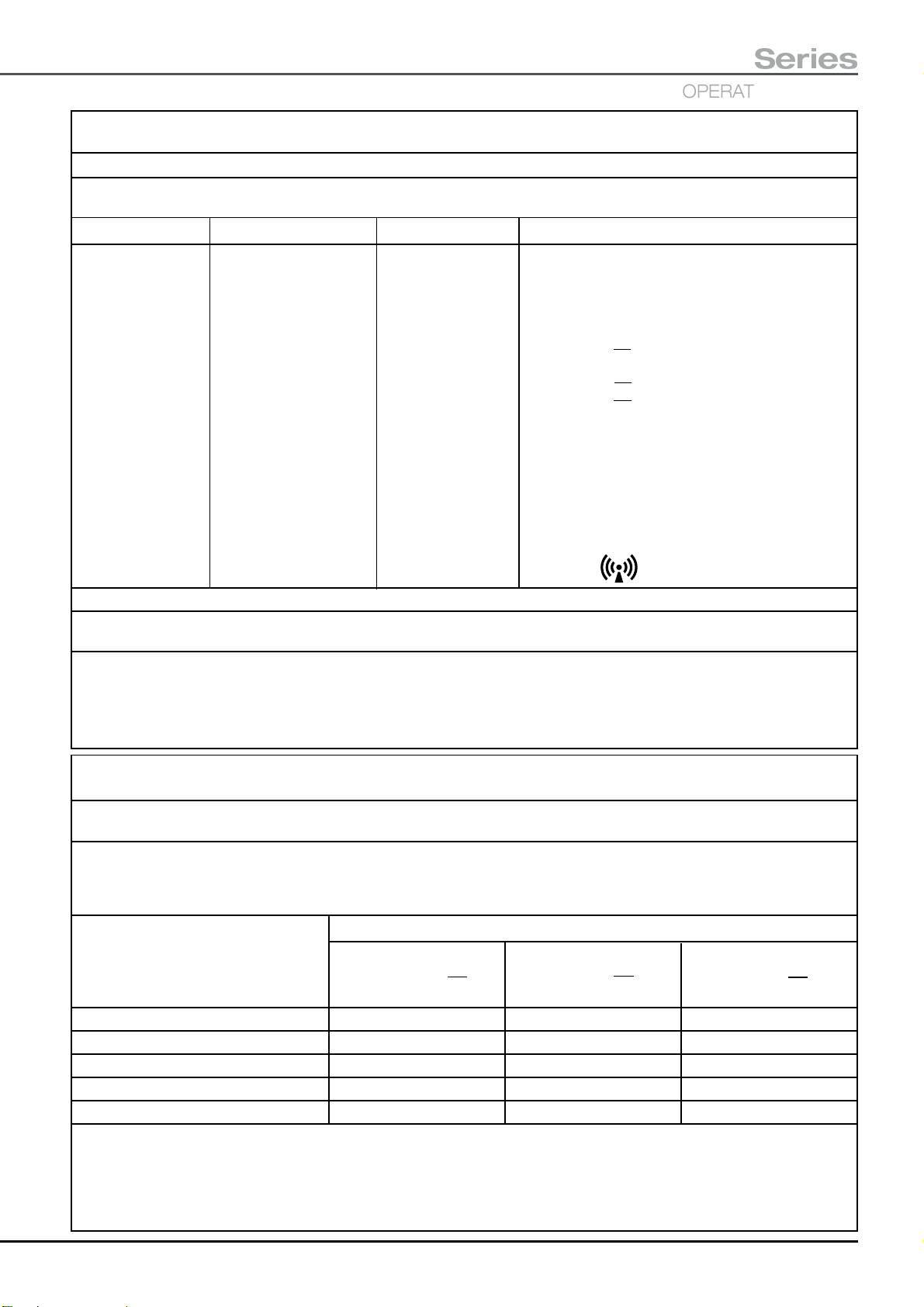
T30
Series
OPERATING TABLES
Table 204 - Guidance and manufacturer’s declaration - electromagnetic immunity - for EQUIPMENT and
SYSTEMS that are not LIFE-SUPPORTING.
Guidance and manufacturer’s declaration - electromagnetic immunity
T30 Tables are intended for use in the electromagnetic environment specified below. The customer or the user of these
operating tables should assure that it is used in such an environment.
Immunity test IEC 60601 test level Compliance level Electromagnetic environment - guidance
Portable and mobile RF communications equipment
should be used no closer to any part of the T30
Table, including cables, than the recommended
separation distance calculated from the equation
applicable to the frequency of the transmitter.
Recommended separation distances
Conducted RF 3Vrms 3V d = 1.2 √
IEC 61000-4-6 150 kHz to 80 MHz
Radiated RF 3V/m 3V/m d = 1.2 √ P 80 MHz to 800 MHz
IEC 61000-4-3 80 MHz to 2,5 GHz d = 2.3 √
where P is the maximum output power rating of the
transmitter in watts (W) according to the transmitter
manufacturer and d is the recommended separation
distance in metres (m). Field strengths from fixed RF
transmitters, as determined by an electromagnetic site
survey,
each frequency range.bInterference may occur in
the vicinity of equipment marked with the following
symbol:
P
P
800 MHz to 2,5 GHz
a
should be less than the compliance level in
NOTE 1 At 80 MHz and 800 MHz, the higher frequency range applies.
NOTE 2 These guidelines may not apply in all situations. Electromagnetic propagation is affected by
absorption and reflection from structures, objects and people.
a
Field strengths from fixed transmitters, such as base stations for radio (cellular/cordless) telephones and land mobile radios, amateur radio,
AM and FM radio broadcast and TV broadcast cannot be predicted theoretically with accuracy. To assess the electromagnetic environment
due to fixed RF transmitters, an electromagnetic site survey should be considered. If the measured field strength in the location in which the
T30 Table is used exceeds the applicable RF compliance level above, the T30 Table should be observed to verify normal operation. If
abnormal performance is observed, additional measures may be necessary, such as reorienting or relocating the T30 Table.
b
Over the frequency range 150 kHz to 80 MHz, field strengths should be less than 3 V/m
Table 206 - Recommended separation distances between portable and mobile RF communications equipment
and the T30 Table - for EQUIPMENT and SYSTEMS that are not LIFE-SUPPORTING.
Recommended separation distances between portable and mobile RF
communications equipment and the T30 Table
T30 Tables are intended for use in an electromagnetic environment in which radiated RF disturbances are controlled. The
customer or the user of the T30 Table can help prevent electromagnetic interference by maintaining a minimum distance
between portable and mobile RF communications equipment (transmitters) and the T30 Table as recommended below,
according to the maximum output power of the communications equipment.
Separation distance according to frequency of transmitter (m)
Rated maximum output 150 kHz to 80 Mhz 80 MHz to 800 MHz 800 MHz to 2.5 Ghz
power of transmitter
W
0.01 0.12 0.12 0.23
0.1 0.37 0.37 0.74
1 1.2 1.2 2.3
10 3.7 3.7 7.4
100 12 12 23
For transmitters rated at a maximum output power not listed above, the recommended separation distance d in metres (m)
can be estimated using the equation applicable to the frequency of the transmitter, where P is the maximum output power
rating of the transmitter in watts (W) according to the transmitter manufacturer.
NOTE 1 At 80 MHz and 800 MHz, the separation distance for the higher frequency range applies.
NOTE 2 These guidelines may not apply in all situations. Electromagnetic propagation is affected by absorption and
reflection from structures, objects and people.
d
= [——]
7
P
√
V
1
d
= [——]
3.5
E
P
√
1
d
= [——]
7
P
√
E
1
T-IM122b P59/77

APPENDIX 1
TRAINING LOG FOR THE ESCHMANN T30 TABLE
NAME POSITION DATE INSTRUCTOR AUTHORIZED BY REVIEW DATE
Ensure that ALL the personnel listed above have been fully trained in the safe use of this T30 Table. This
should include a thorough understanding of all the safety notes and cautions contained within this
‘Instructions for use’ manual .
Photocopy this page as required and ensure that ALL personnel have not passed the review date without
a refresher course. Append additional documents applicable to your unit/hospital (e.g. cross contamination
procedures) and list them below in the space provided, if they should be included in the training.
ADDITIONAL DOCUMENTS
P60/77 T-IM122b

T30
OPERATING TABLES
Series
APPENDIX 2
DECONTAMINATION CERTIFICATE
Make and description of equipment/item:
Catalogue number (REF)*:
Serial Number (SN)*:
This is to certify that the above equipment/item has been decontaminated in accordance with the
attached procedure and that this certificate has been issued by the authorized person detailed
below. The equipment/item has also been suitably marked to show it has been decontaminated in
accordance with the attached procedure and that this certificate has been issued.
Certificate issued by:
Title:
Position:
Hospital/unit address:
Date:
Additional information (optional)
Reason for return:
For the attention of:
* If applicable and known
T-IM122b P61/77

APPENDIX 3
BATTERY MANAGEMENT SHEET FOR THE ESCHMANN T30 TABLE
CAUTION
Continued use of the table batteries in the ‘critically low’ state can damage the batteries.
Batteries within the table base are mains rechargeable, to maintain peak battery performance the table batteries should be placed
‘on charge’ at the end of each day or shift, do not wait a ‘low’ battery indication, it is good practice to charge daily. Batteries must
be charged at the end of the shift when a ‘low’ indication is given and as soon as possible when a ‘critically low’ indication is given.
Batteries should be checked for adequate charge before using the table for any surgical procedure. The orange battery LEDs on the
corded handset indicate a ‘low’ battery and the red LEDs indicate a ‘critically low battery’. When the ‘critically low’ battery warning is
indicated the table cannot be operated by either of the handsets or the footswitch. To continue to operate the table either connect it to
a suitable mains supply and recharge the batteries, or use the standby batteries or control panel. To use the standby batteries the
standby battery switch must be pressed and held depressed whilst the required motions are conducted using the normal controls.
To recharge the table batteries (normal and standby) connect the mains cord supplied (do not use any other cord) into the
mains inlet. Connect the mains cord to a suitable mains supply (check voltage) and switch the supply ‘on’ if controlled by a
switch. The battery charging LEDs will illuminate ‘red’ to indicate ‘bulk’ recharge, ‘amber’ to indicate ‘top-up’ charge and ‘green’
to indicate a fully charged battery on ‘trickle’ charge. Note: The standby control panel can be used even when the ‘critically
low’ battery indication is given but note the warning given in section 5.3.1.4 of the ‘Instructions for Use’.
DATE
TIME TIME
‘ON’ ‘OFF’
BAT’Y IND’N*
MAIN STANDBY
DATE
TIME TIME
‘ON’ ‘OFF’
BAT’Y IND’N*
MAIN STANDBY
* BAT’Y IND’N - Indicate battery state after charge. ‘G = Green or OK’, ‘A = Amber or Low’, or ‘R = Red or Critically Low’ as
indicated on the corded handset. Please photocopy this page and use to record battery charging data.
P62/77 T-IM122b

APPENDIX 4 - Manual handling safety notes and advice
T30
OPERATING TABLES
Series
1 Manual handling
1.1 During configuration or adjustment of the T30 Table
there are occasions where the user should be aware of
the safe practises to be employed during manual handling
or adjustment of parts of the table. For information the
weights of the heaviest accessories commonly used are
listed below. When lifting, carrying or fitting these
accessories it is recommended that care is taken and two
people are employed when required.
Leg section, without mattress, 11.5kg (25.3lb)
Leg section, with 50mm mattress, 12.5kg (27.5lb)
Pre-operative leg section, 5.9kg (13lb)
Head section, without mattress, 7.8kg (17.1lb)
Head section, with 50mm mattress, 8.6kg (18.7lb)
Infill section, 10.8kg (23.7lb)
Orthopaedic short trunk, 22.5kg (49.5lb)
General surgical short trunk,13.5kg (29.7lb)
Long and short trunk 50mm mattress, 1.75kg (3.9lb)
Footrest, without mattress, 5.0kg (11.0lb)
Footrest, including 50mm mattress, 5.8kg (12.7lb)
Tibial nailing accessory, 6.4kg (14.1lb)
1.2 When adjusting a section such as the head and leg
section the weight is partially supported* by the gas springs,
but together with the weight of the patient’s limbs, the total
weight required to be lifted could be much greater than the
weight of the section and mattress*. It is not possible to
quantify this weight exactly as each situation will vary, but
Fig. 4.9 should assist in an approximation, taking into
account the patient’s actual total weight.
These ‘Instructions for use’ advise supporting the weight
of the patient during adjustment of any section, obviously
this requires the intervention of several personnel, some
supporting the patient’s limbs and others adjusting the table
sections.
* Because of the complexities involved in both the way the
patient loading acts on a section, and the assisting force
provided by the gas spring varies, as the section is raised
or lowered about its hinge, the load at a particular point
cannot be exactly stated.
1.3 Manual handling is covered by legislation and the
Manual Handling Operations Regulations 1992 require
employers to avoid the need for employees to carry out
manual handling work that could cause injury by
mechanising processes, or reorganising work, so far as is
reasonably practicable. It states that it is the Duty of
Employees while at work to make full and proper use of
any system of work provided for his use by his employer
to comply with these regulations. To this end the following
publication could be used to create such a system of
working, “Manual Handling in the health services”, Health
and Safety Commission, 1998.
1.4 There are no recommended maximum weights
specified in the “Manual Handling Operations Regulations
1992” or the “Health and Safety (miscellaneous
amendment) Regulations 2002” but the notes following may
be considered useful in compiling a safe working practice.
The reason no specific maximum weights are stipulated is
that factors such as an individuals capabilities (height,
gender, strength, etc.) the load (size, availability of handholds, weight, etc.) the task (motion required, duration,
distance, etc.) the environment and other factors all need
to be assessed when considering the task.
2 How to lift safely
Where the ‘load’ is a patient the person or team must
communicate with the patient throughout the lifting
procedure if they are conscious. Here are some important
points, using a basic lifting operation as an example, these
points can be remembered as the four ‘Ps’.
i PLAN - Plan the lift.
Where is the load to be placed? Use appropriate
handling aids if possible. Do you need help with the
load? Remove obstructions such as discarded
wrapping materials. For a long lift, such as floor-toshoulder height, consider resting the load midway
on a table or bench in order to change grip.
ii PREPARE - Prepare load and position feet.
Make the load secure, easy to hold, safe and
compact. Clear obstructions and any floor hazards
giving good visibility and space. Position the feet
apart, giving a balanced and stable base for lifting
with the leading leg as far forward as is comfortable.
iii POSTURE - Adopt a good posture.
When lifting from a low level, bend the knees. But
do not kneel or overflex the knees. Keep the back
straight (tucking in the chin helps). Lean forward a
little over the load if necessary to get a good grip.
Get as close to the load as possible. Keep the
shoulders level and facing in the same direction as
the hips. Try to keep the arms within the boundary
formed by the legs, elbows tucked in. The best
T-IM122b P63/77

position and type of grip depends on the
circumstances and individual preference; but it must
be secure. A hook grip is less tiring than keeping
the fingers straight. If you need to vary the grip as
the lift progresses, do it as smoothly as possible.
iv PERFORM - Keep close to the load.
Keep the load close to your trunk for as long as
possible. Keep the heaviest side of the load next to
your trunk. If a close approach to the load is not
possible, slide it towards you before trying to lift. Lift
smoothly, keeping control of the load. Don’t twist
the trunk when turning to the side.
3 Team lifting
Never be pushed into lifting with others if you are unsure
about their knowledge or ability. Say NO. The key factors
involved in team lifting are the three 'Cs':
i Communication
There must be a team leader to direct the procedure.
The leader should give a command to lift or move,
first making sure that every member of the team
understands the command to be used. The leader
must be in control of the procedure from start to
finish.
ii Cooperation
The team must lift together. It helps if the team
members are similar in height and build (but this is
not essential). The team needs to have trust and
confidence in each other. If one member of a team
fails to lift or move properly it is probable that
someone will be injured.
iii Coordination
The team members must communicate, if only by a
nod of the head. They must indicate when they are
ready. If they are tiring or need a break, telling other
members in sufficient time to allow the load to be
lowered safely, before they drop it, is important.
P64/77 T-IM122b

APPENDIX 5 - The traction accessories
T30
OPERATING TABLES
Series
Fixed knuckle
Intermediate
knuckle
Traction beam
Perineal post shown
without mattress
Orthopaedic
short trunk
section
Fixed knuckles
Release pin
Stub
Intermediate
knuckle
Traction upright
support tube
Sidebar
1
Note: Traction beams can
be fitted with or without
an intermediate knuckle.
Fig. A5-1
Perineal post
(shown ghosted)
in an alternative
location
Release pin location
hole (in sleeve)
Locking handle
Fig. A5-2
Accessory slider
(optional)
2
Offset traction carrier
Fig. A5-3
Attaching the intermediate knuckle, traction
beam, and traction unit
CAUTION
Reverse Trendelenburg will be very limited with
traction beams fitted. Take care, they may collide
with the floor after only a small movement. Do
not overload the traction beams.
Traction beams can be attached directly to either the fixed
knuckle on the orthopaedic trunk section, or to an
intermediate knuckle attached to a fixed knuckle (see
Fig. A5-1). Fitting an intermediate knuckle assembly allows
the traction beam to be offset. The perineal post (see Fig.
A5-2) can be placed on either side of the orthopaedic short
trunk section.
Perineal post. Locate pin into socket and twist until the
location pin is fully located into its socket. Ensure it is
inserted fully into the socket before use, it should not be
possible to rotate the post within the socket when
assembled correctly. Attach the perineal post mattress.
Intermediate knuckles and traction beams. Attach by
aligning the release pin’s location hole with the release pin
of the stub (see Fig. A5-2). Push fully home until the release
pin has been located, check by pulling away from table.
Accessory slider. If required, slide one onto the traction
beam (see Fig. A5-3) where required. Tighten locking clamp
(2) when in position.
Offset traction carrier. Slide onto the beam as shown in
Fig. A5-3 with the traction upright support tube inside or
outside the beam as required. Lock in place with the drop
handle clamp (1).
Traction assembly. Insert the traction upright into the
carrier’s support tube with a secondary clamp positioned
above (see Fig. A5-4). Lock in place with the drop handle
clamp (1). Position the secondary clamp against the carrier
and lock in place with its drop handle clamp (2).
WARNING
Traction assembly
2
Traction
Secondary clamp
1
Sidebar
upright
Fig. A5-4
T-IM122b P65/77
Do not use an adjustable support as a means
of increasing table stability.
An adjustable support REF 81-791-15 can be clamped onto
the small sidebar on the end of the traction beam using a
universal clamp REF TA-020-1084 (UK or Euro).
Removing the traction components
Remove traction components from the table by releasing
the clamps and reversing the sequence above. To minimise
weight do not remove the traction carrier with the traction
assembly, or remove the beam with the traction carrier.
To remove a beam or an intermediate knuckle, press the
release pin in until they can be withdrawn.
Store all the components and accessories onto the
appropriate trolley as detailed in Appendix 8.

Adjusting the traction assembly (see Fig. A5-5)
WARNING
Always support the weight of the traction
assembly and the patient’s leg before releasing
the traction unit’s drop handle clamp (1). Always
support the patient’s limbs during adjustment and
repositioning. Ensure all clamps are tightened
before use and applying traction. When applying
traction do not strain the traction upright.
Height (A). Release drop handle clamps (1 and 2).
Position as required and clamp in place with clamp (1).
Position the secondary clamp against the support tube and
clamp in place with clamp (2).
Knuckles. Adjusted by releasing the locking handle (rotate
clockwise when viewed from above). Adjust the angle and
lock in place, do not overtighten, only light finger pressure
is required.
Coarse traction adjustment. Wind the traction handle
clockwise or anti-clockwise (depressing the ratchet release
button if required) until approximately 150mm of traction
arm is visible. Release the carrier’s drop handle clamp (3)
and adjust the carrier’s position as required for the patient’s
limb. Clamp the carrier in place with the clamp (3).
Fine traction adjustment. Rotate the traction handle
clockwise, a ratchet will automatically lock the degree of
traction applied. Note: The traction handle can be folded in
(flat) when required, this will not inhibit traction adjustment.
Line of traction (B, C and D). Release the traction
assembly’s drop handle clamp (4) and adjust the line of
traction by rotating (B) or tilting (C) the ball swivel assembly.
Tighten clamp (4) after adjustment. The boot can be rotated
(D) about the traction arm by releasing clamp (5). Tighten
clamp (5) after adjustment, do not use excessive force.
Releasing traction. Hold the traction handle, depress the
ratchet release button and rotate the traction handle anticlockwise. Release the button and then the handle to lock
the degree of traction applied.
Traction
handle
1
(150mm
approx.)
Ball swivel
assembly
A
C
B
release button
D
5
4
Traction upright
2
3
Locking handle
Ratchet
Traction
arm
Traction handle
Fig. A5-5
P66/77 T-IM122b

A2
A3
A1
T30
Series
OPERATING TABLES
Using the traction boot
Attaching the boot. Refer to Fig. A5-6. To secure the
patients foot and ensure firm control during traction, check
the straps are adjusted correctly as follows:
Six adjustment points secure the patient’s foot in the boot.
B
Release all self fastening (hook and loop) straps and place
the patient’s foot fully into the boot. Check the foot is located
correctly with the heel in the base of the boot. Fasten the
straps firmly in the following sequence:
C
i - Blue strap nearest toes 'A1'
ii - Blue strap adjacent to above ‘A2’
iii - Remaining blue strap 'A3'
iv - Left or right black strap 'B'
ev - Remaining black strap 'B'
vi - Grey strap 'C'
Fitting boot to traction unit. Refer to Fig. A5-7. Attach
the boot to the traction unit by sliding the boot release knob
back and hooking the slot of the boot adapter over the bar
of the location block. Press the boot adapter down and
into the location block, release the knob. The locking pin
will engage. Check the boot is locked in place.
Removing the boot. Refer to Fig. A5-7. Support the
patient’s foot during removal from the boot. Release the
applied traction. Release the boot from the traction unit by
sliding the boot release knob away from the boot. Lift the
boot out of the location block. Unfasten all the straps to
release the patient’s foot from the boot.
Location block
Boot
release
knob
4
3
Locking pin
Location bar
1
Fig. A5-6
Locking pin
location
Location slot
Fig. A5-7
2
Boot
adapter
Using pins and wires with stirrups (Fig. A5-8)
In order to apply traction through Denham or Steinman
pins with a Bohler Stirrup, an insulated traction bracket
(1) is required. This is assembled as shown in Fig. A5-8
with the Bohler Stirrup (2) located between the two plastic
spacers (3) and held in place with the threaded metal disk
(4). The complete assembly can then fitted to the traction
unit in the same way as a boot (see above).
Fig. A5-8
T-IM122b P67/77

APPENDIX 6 - The Tibial Nailing Accessory
Assembling the Tibial Nailing Accessory
3
2
Reverse Trendelenburg will be limited once the
traction unit has been fitted. Take care, the
beam may collide with the floor after only a
Tibial nailing
upright assembly
Orthopaedic
short trunk
Offset traction carrier
Secondary
clamp
1
Tibial nailing beam
Traction
assembly
4
Tibial
nailing
beam
5
Fig. A6-1
1
Fig. A6-2
small movement.
When not in use remove the beam. It is good
practice to turn the beam stubs to face in (i.e.
under the table) and away from the tibial nailing
accessory.
The Tibial Nailing Accessory is attached to either side of
the orthopaedic trunk section after removal of the
appropriate left, or right hip section. The following sequence
is recommended to eliminate lifting heavy assemblies.
Tibial nailing upright assembly. Attach as shown in
Fig. A6-1 by aligning the guide pin (2) with the location
hole (1). The attachment block (5) should be held vertical
to enable the anti-rotation pin (3) and the catch (4) to
engage correctly. Ensure the locking catch and the antirotation pin have engaged correctly by gently trying to twist
and pull the assembly away from the table.
Tibial nailing beam. Place into the tibial nailing upright
assembly as shown in Fig. A6-2. The clamp (1) may need
to be slackened. Tighten clamp (1) after assembly.
Accessory slider. If required, slide one onto the tibial
nailing beam (see Fig. A6-3) where required. Tighten its
locking clamp when in position.
Traction assembly. Follow Appendix 5 and attach the
offset traction carrier and traction assembly onto the beam.
The final assembly is shown in Fig. A6-3. Note the position
of the secondary clamp which should always be used (i.e.
on the traction upright above the offset traction carrier).
Note: The traction assembly can be positioned below the
tibial nailing beam with the secondary clamp positioned
on the traction upright above the offset traction carrier.
Boot and application of traction. Attach the required boot
and apply traction as detailed in Appendix 5.
Removing the Tibial Nailing Accessory
IMPORTANT Before removal adjust to minimum height
and vertical. To minimise weight do not remove the beam
with the traction unit or the upright assembly with the beam.
To remove reverse the procedure above. The secondary
clamp can be left on the traction upright.
CAUTION
To release the tibial nailing upright assembly lift the release
catch (4, Fig. A6-1) and slide the assembly out and away
Traction
upright
Accessory slider (optional)
Offset traction carrier
from the short trunk.
Store all the components onto the appropriate trolley as
detailed in Appendix 8.
Fig. A6-3
P68/77 T-IM122b

Adjusting the Tibial Nailing Accessory (Fig. A6-4)
T30
OPERATING TABLES
Series
WARNING
Always support the weight of the outer tibial
nailing upright (3) and the patient’s leg (if
applicable) before releasing the clamp (4) and the
locking knob (5). Always support the patient’s
limbs during adjustment and repositioning.
Ensure all clamps are tightened before use.
Height (A). Adjust by releasing the clamp (4) and moving
the outer tibial nailing upright (3) relative to the inner
assembly (7). Tighten the drop handle clamp.
Rotation (B). Rotate the upright (3) about the attachment
block by releasing the locking knob (5). When the required
angle has been obtained only light finger pressure is
required to lock the assembly, do not overtighten.
Condylar knee support (C and D). The angle and
effective length of each knee support can be adjusted by
releasing the appropriate locking knob (2). Tighten locking
knobs after adjustment.
Knee width (E). The gap (E) between the knee supports
can be adjusted by releasing locking knobs (1). Tighten
the locking knobs after adjustment.
Traction unit and boot. The traction unit and boot are
used and adjusted as detailed in Appendix 5.
1
E
D
2
6
7
2
C
3
A
4
B
CAUTION
Always ensure that clamps are tightened after
use (especially the top condylar clamp screw),
they can vibrate loose and be lost during
transportation.
Changing the knee support mattress
To change the knee support mattress remove the outer
locking knob (2, Fig. A6-4) and the associated condylar
knee support. This enables the mattress to be withdrawn
from its support tube. After replacing the new mattress
ensure the condylar knee support is replaced and the
locking knob is tightened.
5
Fig. A6-4
T-IM122b P69/77

APPENDIX 7 - The Lateral Femoral Nailing Accessory
Attaching the Lateral Femoral
Nailing Accessory
The Lateral Femoral Nailing Accessory is used in
conjunction with the traction accessories detailed in
Appendix 5. These are assembled and used as detailed in
Appendix 5.
3
2
1
5
4
Fig. A7-1
The Lateral Femoral Nailing Accessory is attached to either
side of the orthopaedic short trunk section after removal
of the appropriate (left or right) hip section.
Attach the Lateral Femoral Nailing Accessory as shown in
Fig. A7-2 holding the accessory vertical and aligning the
guide pin (2) with the guide pin location hole (1).
With the accessory held vertical push in towards the table
until the anti-rotation pin (3) and the catch (4) engage.
When attached ensure the locking catch and anti-rotation
pin have engaged correctly by gently trying to twist and
pull the accessory away from the table.
When fitted a typical assembly should be as shown in
Fig. A7-3 (shown fitted to left hand side of table).
Removing the Lateral Femoral
Nailing Accessory
To remove the Lateral Femoral Nailing Accessory lift the
release catch (4, Fig. A7-1). This enables the assembly to
be removed by pulling it out and away from the orthopaedic
short trunk.
1
Store the Lateral Femoral Nailing Accessory on the trolley
as detailed in Appendix 8.
Fig. A7-2
Fig. A7-3
P70/77 T-IM122b
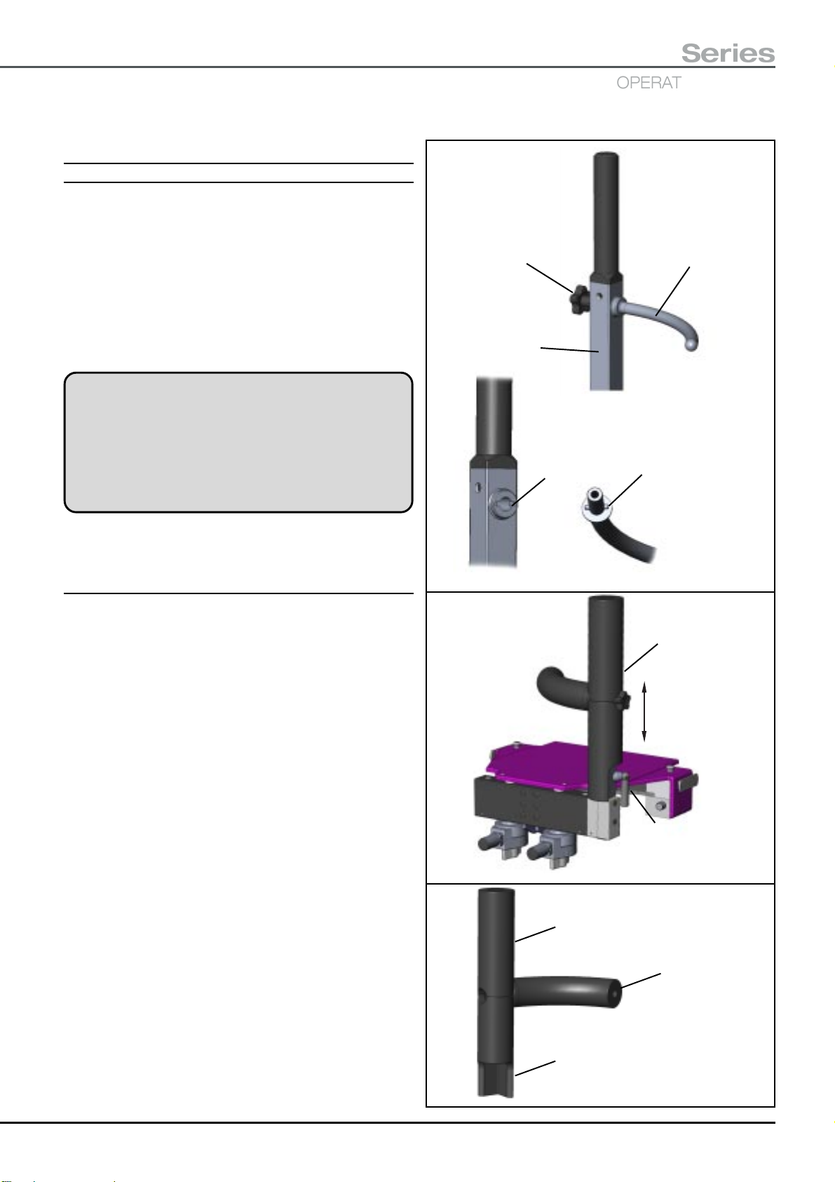
Adjusting the Lateral Femoral
Nailing Accessory (Fig. A7-4)
Orientation. Note: During this adjustment slide the curved
mattress away from the upright to aide alignment.
Check that the curved counter traction pin (2) is correctly
oriented (i.e. for left or right leg). If adjustment is required
slacken the knob (1) until the pin (5) can be pulled clear of
the slot (4). Rotate the curved counter traction pin to the
required orientation and tighten the knob. Check the
location pin has engaged in the slot correctly, the knob
has been tightened and that the mattress has been returned
to its correct position.
WARNING
Always support the weight of the lateral femoral
nailing upright and the patient’s leg (if applicable)
before releasing the drop handle clamp. Always
support the patient’s limbs during adjustment and
repositioning. Ensure the clamp is tightened
before use.
T30
Series
OPERATING TABLES
1
3
4
5
2
Height (Fig. A7-5). To adjust the height, release clamp (2),
raise or lower the upright (1) then tighten clamp (2).
Fitting or changing the mattress.
The three parts of the mattress simply push onto the
appropriate parts of the assembly. Use Fig. A7-6 to identify
the mattresses and their location. Ensure the orientation
of each section is correct so they fit together as shown.
To fit or change the ‘bottom’ mattress remove the curved
counter traction pin (2, Fig. A7-4). Take care when pushing
the ‘bottom’ mattress past the bosses on the upright. When
replacing the curved counter traction pin check the location
pin has engaged in the slot correctly and the knob has
been tightened.
Fig. A7-4
1
2
Fig. A7-5
Top mattress
Counter traction
mattress
Bottom mattress
Fig. A7-6
T-IM122b P71/77
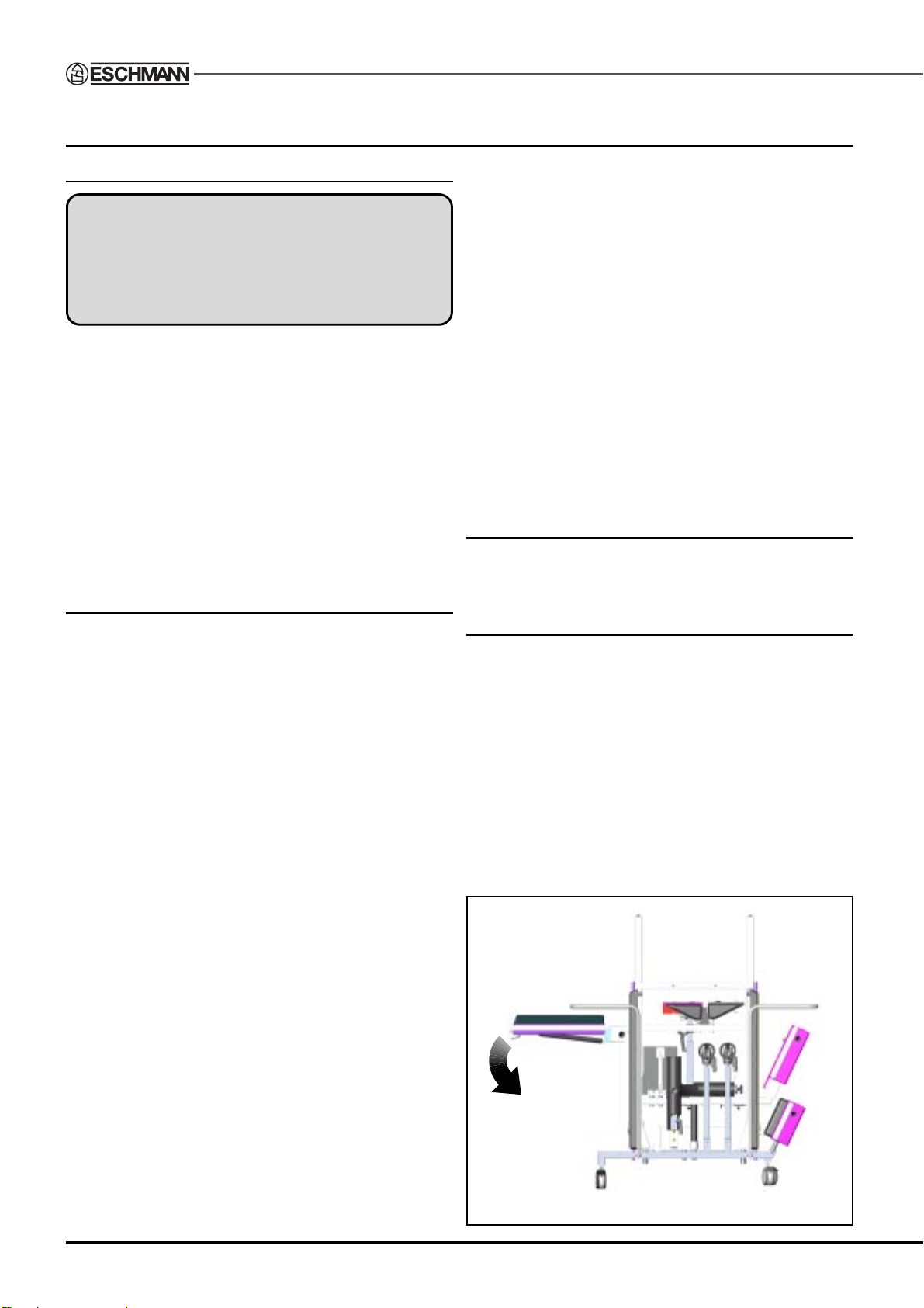
APPENDIX 8 - The orthopaedic accessory trolley
The traction accessory trolley
WARNING
For safety, it is recommended that the trolley is
moved by two people, one at each end. Always
use the handles and do not push sideways where
marked with the ‘Pushing prohibited’ symbol.
Also note bold text comments in Fig. A8-2.
The orthopaedic accessory trolley has been designed for
use as storage unit and an aide to manual handling for the
sections and traction accessories of a T30 Table. To
minimise the space required to store all the accessories
they have been positioned in a compact way. To place and
remove some items they require correct positioning and
orientation and the use of catches etc. this is detailed below.
All castors of the trolley incorporate a rocker style foot
operated brake shown in Fig. A8-2. To apply the brake
press the bottom of the lever down until it locks down with
a click. To release the brake apply pressure to the top of
the lever until it releases. It is advised that the castors are
locked whilst loading and unloading the accessory trolley.
Operation
Fig. A8-2 shows how the orthopaedic accessory trolley
should be loaded with the T30 Table’s removable sections
and orthopaedic accessories. Ensure all clamps are
tightened after storing accessories, this will ensure clamp
handles etc. will not vibrate loose and become detached.
Ensure that all the locations for the components are used
correctly and that all sections and orthopaedic accessories
are securely attached on the trolley at all times.
Leg section
When placing the leg section onto the trolley the following
procedure is advised.
i Ensure the trolley castor brakes have been applied.
ii Adjust the leg section whilst on the table to horizontal
and remove it from the table in the normal way,
continue to hold it horizontal.
iii Slide the leg section into the trolley’s location blocks
evenly until the locking catches engage with a click.
The section will slide in easily if the weight of the
section is gently supported with both hands.
iv Check that the section is fully inserted and the safety
catches have engaged by gently pulling on the leg
section. Both release buttons should be out when the
section has been correctly located and locked.
v Raise the leg section’s release bar and adjust it down
as shown on Fig. A8-1. IMPORTANT Do not leave
the leg section horizontal.
iii Remove the leg section using the buttons in the
normal way, continue to hold it horizontal.
iv Fit the leg section into table in the normal way and
check it is secure.
Tibial nailing accessory
This accessory is located onto the trolley upside down
compared to the normal orientation when in use. When
fitting this accessory to the trolley, ensure that it is locked
onto the trolley by tightening the appropriate drop handle
clamp and tighten all other clamps.
Offset carriers
These are locked onto the trolley in the same way as the
tibial nailing accessory above using a drop handle clamp.
Lateral femoral nailing accessory
This accessory is locked onto the trolley using its catch in
the same way as it is used to secure it to the short trunk
section, see Appendix 7.
Care
Once a week check the trolley for any signs of damage
that requires attention and arrange remedial action if
required.
Service
The trolley does not require servicing, however a check
for any physical damage that could impair the function or
compromise safety is recommended, plus occasional
cleaning and light lubrication of the leg sections location
blocks and the castors.
Every six months the trolley should be inspected by a
competent person (i.e. an Eschmann trained Engineer) to
ensure that it is safe. This inspection can be arranged by
the Eschmann After Sales Service Department, see inside
front cover for contact details.
To remove the leg section proceed as follows.
i Ensure the trolley castor brakes have been applied.
ii Adjust the leg section to horizontal.
Fig. A8-1
P72/77 T-IM122b
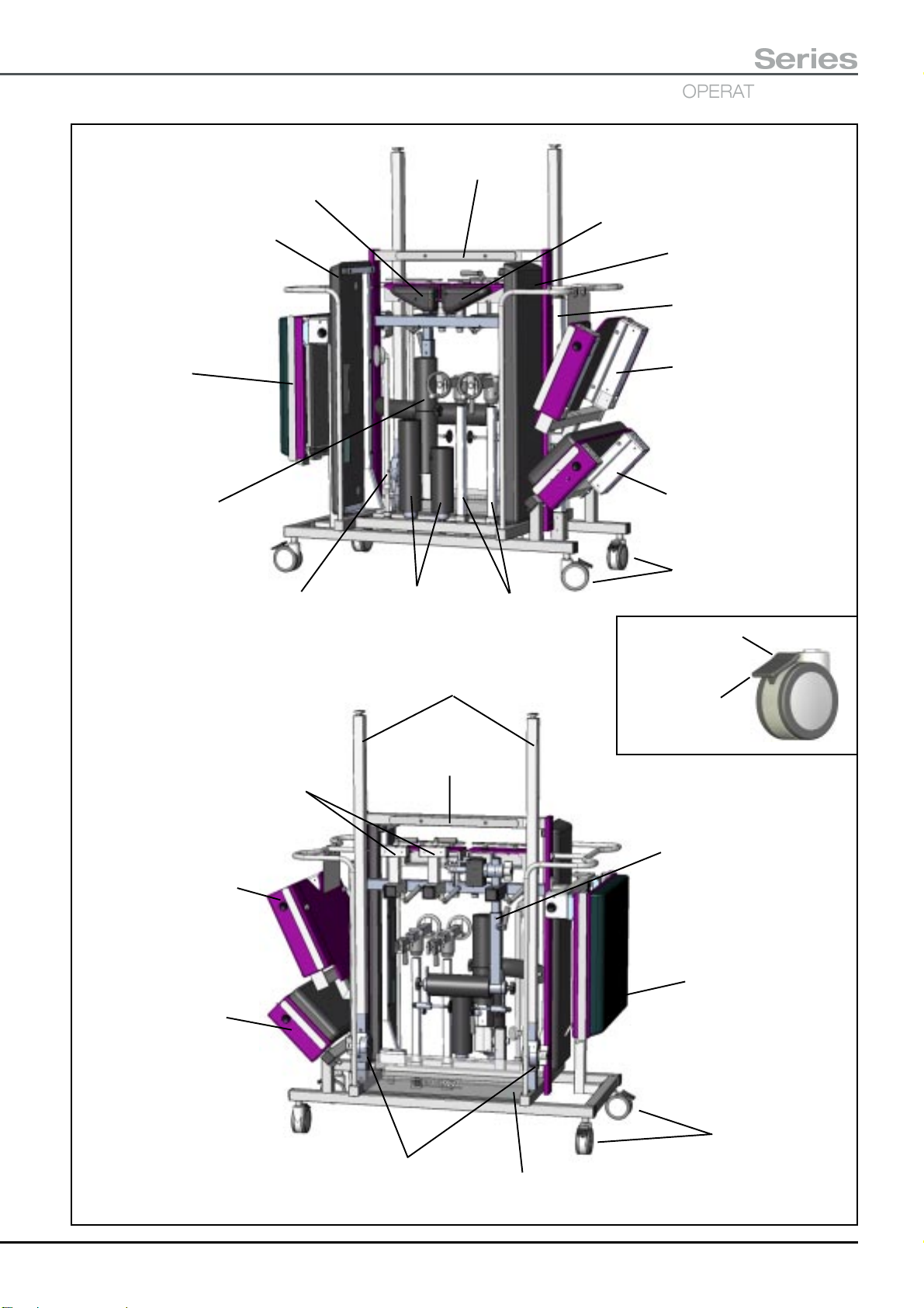
T30
OPERATING TABLES
Series
Left hand
hip section
Left hand pre-operative
leg section
Leg section.
FOLD DOWN
AFTER FITTING.
Lateral femoral
nailing accessory
Adjustable
support
Accessory bar
Perineal
posts
Traction beam (on
intermediate knuckle)
Traction
units
Right hand
hip section
Right hand pre-operative
leg section
Tibial nailing
traction beam
General surgical short
trunk. Caution - Grease
may be present on stubs
when section removed.
Infill section.
Lockable
castors (4)
Press here to
release castor.
Press here to
brake castor.
Offset carrier.
CLAMP IN PLACE
WHEN FITTED.
General surgical
short trunk
Infill section
Accessory bar
Intermediate knuckle.
ENSURE KNUCKLE
IS TIGHTENED.
Tibial nailing accessory.
CLAMP IN PLACE
WHEN FITTED.
Leg section.
FOLD DOWN
AFTER FITTING.
Lockable
castors (4)
Accessory tray
Fig. A8-2
T-IM122b P73/77

APPENDIX 9 - Orthopaedic accessory and spares list
The catalogue (REF) numbers for the standard orthopaedic T30 Table accessories are shown in the following list (UK
sidebars). This list may not be exhaustive as new accessories are added to the range. Please check with Eschmann
Equipment for the latest additions. Some of the accessories listed below are also available with alternative sidebars,
please contact Eschmann for more information.
Catalogue Number (REF) Description
TA-030-4142 Pre-operative leg sections (1 pair)
TA-030-5161 Infill section *
TA-040-1135 Orthopaedic trolley
TA-040-3133 Orthopaedic docking cart
TA-040-3134 Orthopaedic docking cart, complete with an Orthopaedic short trunk section
TA-050-1127 General surgical, trunk section mattress (long and short)
TA-050-1128 Orthopaedic, trunk section mattress (long and short)
TA-050-1132 Tibial nailing/Perineal post (short) mattress
TA-050-1141 Lateral femoral nailing, mattress set
TA-050-1154 Perineal post (long) mattress
TA-050-1164 General surgical mattress set
TA-050-1166 Orthopaedic trunk mattress set
TA-050-1167 Hip section mattress (pair)
TA-050-1158 Lateral femoral nailing, counter traction mattress
TA-050-1159 Lateral femoral nailing, top mattress
TA-050-1160 Lateral femoral nailing, bottom mattress
TA-050-1129 Infill section, mattress
TA-100-3162 General surgical short trunk section *
TA-100-3165 General surgical kit
4
TA-100-2000 Orthopaedic short trunk section *
TA-110-1137 Traction beam
TA-110-1168 Tibial nailing beam
TA-110-2147 Offset traction carrier
TA-110-3138 Traction unit
TA-110-4144 Accessory slider
TA-110-5148 Intermediate knuckle
TA-120-1155 Hip sections (1 pair)
TA-120-2145 Tibial nailing attachment*
TA-120-3140 Lateral femoral nailing attachment*
TA-120-4151 Short perineal post
TA-120-4152 Long perineal post
TA-130-1143 Secondary clamp
TA-130-3139 Inline insulated traction bracket
81-943-09 Orthopaedic boot, adult
1
2
3
* These items require a mattress which is supplied separately
1
TA-050-1141 inc.: TA-050-1158 TA-050-1159 TA-050-1160
2
TA-050-1164 inc.: TA-050-1129 TA 050-1127 T20-441-2095 T20-431-2094
3
TA-050-1166 inc.: T20-431-2094 TA-050-1128
4
TA-100-3165 inc.: TA-030-5161 TA-100-3162 T00-321-0001 (and applicable mattresses)
P74/77 T-IM122b

T30
Series
OPERATING TABLES
APPENDIX 10 - Orthopaedic positioning and imaging procedures
Dynamic hip screw
Positioning for dynamic hip screw can be achieved with the healthy leg positioned away from the surgical site in a
Direct Placement Leg Holder (DPLH). The image intensifier should be brought into position between the patients legs
and the hip section should be removed. Where this procedure is carried out on an elderly patient, the healthy leg may
be positioned using another traction beam with the healthy leg placed in a traction boot. Such patient positioning
allows for:
Good distal imaging of the injured femur in both anterior/posteria (A/P) and lateral.
Good imaging of the fracture site in both A/P and Lateral.
Good imaging of the hip in both A/P and Lateral.
The pictures below illustrate the following:
Picture 1 – A/P imaging, good leg positioned using a Direct Placement Leg Holder.
Picture 2 – Lateral imaging, good leg positioned using a Direct Placement Leg Holder.
Picture 3 – Healthy leg positioned using another traction beam.
Picture 1
Picture 3
Picture 2
T-IM122b P75/77

Tibial nailing
Positioning for tibial nailing can be achieved by positioning the patient using the orthopaedic lower trunk section. The
good leg can be supported in a Direct Placement Leg Holder (DPLH) or traction boot (as Picture 3 for dynamic hip
screw). The tibial nailing attachment is attached to the side of the orthopaedic short trunk section with tibial nailing
traction beam, traction carrier and upright (see Picture 1). The hip section should be removed and then the tibial nailing
accessory can be adjusted to allow for A/P and Lateral imaging.
The pictures below illustrate the following, with the good leg positioned using a Direct Placement Leg Holder:
Picture 1 – Preparation and positioning.
Picture 2-4 – Various imaging possibilities (note angle of traction beam).
Picture 5 – Use of stirrup, pins and wire to replace traction boot.
Picture 1
Picture 3 Picture 4
Picture 2
Picture 5
P76/77 T-IM122b

T30
Series
OPERATING TABLES
Retrograde Femoral Nailing
Positioning for retrograde femoral nailing can be achieved by positioning the patient using the general surgical short
trunk section with the infill section attached. The healthy leg can be placed in either a Direct Placement Leg Holder or
in a traction boot, using a second traction beam (as Picture 3 for dynamic hip screw). Such patient positioning allows
for Easy access to the front of the knee.
The pictures below illustrate the following, with the good leg positioned using a Direct Placement Leg Holder:
Picture 1 – Preparation and positioning.
Picture 2 – Lateral imaging of the whole femur.
Picture 3 – A/P imaging of the distal femur.
Picture 1 Picture 2
Picture 3
T-IM122b P77/77


Eschmann Equipment, Peter Road, Lancing, West Sussex, BN15 8TJ, England.
Tel: +44 (0) 1903 753322. Fax: +44 (0) 1903 875789. www.eschmann.co.uk
 Loading...