

Page 1
T20-a
OPERATION TABLE
Service manual
111707
T-SM47j
Page 2
Preliminary
Information
Technical data
Technical
description
Read these Instructions before use
Keep these ‘Instructions’ in a safe convenient place for future reference. Read in conjunction
with the Publications detailed in Section 1.1.
Eschmann After Sales Service Department
Safety notes
Maintenance
Part removal
adjustment
replacement
The Eschmann After Sales Service Department is staffed and equipped to provide advice and
assistance during normal office hours. To avoid delays when making enquiries, please quote the
Model and Serial Number of your Operation T able which is shown on the Serial Number plate, the
location of which is shown below. Please ensure you include all alpha and numeric digits of the
Serial Number.
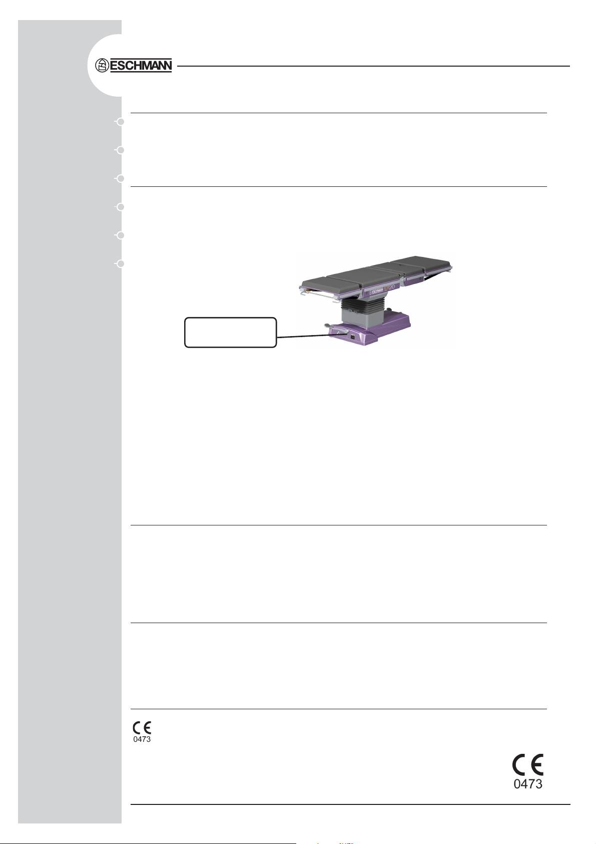
The Serial Number
plate is located here
For further information visit www.eschmann.co.uk
All correspondence relating to the after sales service of Eschmann Equipment to be addressed to :
UK Customers
Eschmann Equipment, Peter Road, Lancing, West Sussex BN15 8TJ, England.
T el: +44 (0) 1903 765040. Fax: +44 (0) 1903 875711.
Overseas Customers
Contact your local distributor. In case of doubt contact Eschmann Equipment.
Patents and Trade marks
The ESCHMANN name and logo are registered trade marks of Eschmann Holdings Limit ed.
“Eschmann Equipment” is a trading name of Eschmann Holdings Limit ed.
“T20-a” is a trade mark of Eschmann Holdings Limited .
Patents : Worldwide Patents Pending.
Copyright © 2005 Eschmann Holdings Limited
All rights reserved. This booklet is protected by copyright. No part of it may be reproduced, stored in a
retrieval system or transmitted in any form or by any means, electronic, mechanical, photocopying,
recording or otherwise without written permission from Eschmann Holdings Lim ited.
The information in this publication was correct at the time of going to print. The Company, however,
reserves the right to modify or improve the equipment referred to.
The CE marking affixed to the product certifies that it complies with the
European Medical Devices Directive 93/42/EEC and related legislation.
T-SM47j July 2005
Service manual
Page 3

T20-a
OPERATION TABLE
CONTENTS
1.0 Preliminary information
1.0 Preliminary information . . . . . . . . . . . . . . . . . . . 5
2.0 Technical data
2.1 Weights . . . . . . . . . . . . . . . . . . . . . . . . . . . . . . . 8
2.2 Dimensions . . . . . . . . . . . . . . . . . . . . . . . . . . . . 8
2.3 Movements . . . . . . . . . . . . . . . . . . . . . . . . . . . . 8
2.4 Table loading . . . . . . . . . . . . . . . . . . . . . . . . . . . 8
2.5 Electrical . . . . . . . . . . . . . . . . . . . . . . . . . . . . . . 8
2.6 Classification and symbology . . . . . . . . . . . . . . 9
2.7 Use in conjunction with other equipment . . . . . . 9
2.8 Standards compliance . . . . . . . . . . . . . . . . . . . . 9
2.9 Environmental conditions . . . . . . . . . . . . . . . . . . 9
3.0 Technical description
3.1 Power supply assembly . . . . . . . . . . . . . . . . . . 13
3.2 Control electronics . . . . . . . . . . . . . . . . . . . . . . 13
3.2.1 Overview . . . . . . . . . . . . . . . . . . . . . . . . . . 13
3.2.2 Handset overview . . . . . . . . . . . . . . . . . . . . 14
4.0 Safety warnings
4.1 ‘Service position’ . . . . . . . . . . . . . . . . . . . . . . . 16
4.2 Lifting . . . . . . . . . . . . . . . . . . . . . . . . . . . . . . . 16
4.3 M10 trunk screw removal . . . . . . . . . . . . . . . . 16
4.4 Trend and tilt actuator removal . . . . . . . . . . . . . 16
4.5 Working with mains voltage . . . . . . . . . . . . . . . 16
4.6 Gas springs . . . . . . . . . . . . . . . . . . . . . . . . . . . 16
4.7 Hot parts on PCAs . . . . . . . . . . . . . . . . . . . . . 16
4.8 Biological contamination . . . . . . . . . . . . . . . . . 16
4.9 Connection of leads . . . . . . . . . . . . . . . . . . . . . 16
4.10 Leaking batteries . . . . . . . . . . . . . . . . . . . . . . . 16
5.0 Maintenance
5.1 Power supply assembly . . . . . . . . . . . . . . . . . . 17
5.2 Table fault finding . . . . . . . . . . . . . . . . . . . . . . . 17
5.2.4 Break motion control . . . . . . . . . . . . . . . . . 17
5.2.5 Trunk section connector blocks . . . . . . . . . 17
5.3 Fuse location . . . . . . . . . . . . . . . . . . . . . . . . . . 17
5.4 Service schedule and safety check . . . . . . . . . 18
6.0 Part removal/adjustment/
replacement
6.1 General . . . . . . . . . . . . . . . . . . . . . . . . . . . . . . 20
6.2 Table base and column covers . . . . . . . . . . . . 20
6.2.2 Base covers . . . . . . . . . . . . . . . . . . . . . . . . 20
6.2.2.1 Removal of base covers . . . . . . . . . . 20
6.2.2.2 Replacing base covers . . . . . . . . . . . 21
6.2.3 Access to column . . . . . . . . . . . . . . . . . . . . 21
6.2.3.2 Lower column access . . . . . . . . . . . . 21
6.2.3.3 Lower-mid column access . . . . . . . . 21
6.2.3.4 Upper-mid column access . . . . . . . . 21
6.2.3.5 T op of column access . . . . . . . . . . . . 23
6.2.4 Telescopic covers . . . . . . . . . . . . . . . . . . . . 23
6.2.4.1 Removal of telescopic covers . . . . . . 23
6.2.4.2 Refitting the telescopic covers . . . . . 23
6.2.5 Bellows . . . . . . . . . . . . . . . . . . . . . . . . . . . . 23
6.2.5.1 Removal of the bellows . . . . . . . . . . . 23
6.2.5.2 Replacing the bellows . . . . . . . . . . . . 24
6.3 Table base components . . . . . . . . . . . . . . . . . . 24
6.3.2 Batteries . . . . . . . . . . . . . . . . . . . . . . . . . . . 24
6.3.3 Pedal dampers . . . . . . . . . . . . . . . . . . . . . . 24
6.3.4 Front wheels . . . . . . . . . . . . . . . . . . . . . . . . 25
6.3.5 Castors . . . . . . . . . . . . . . . . . . . . . . . . . . . . 25
6.3.5.1 Castor assembly . . . . . . . . . . . . . . . . 25
6.3.5.2 Castor wheels . . . . . . . . . . . . . . . . . . 25
6.3.6 Brake pads . . . . . . . . . . . . . . . . . . . . . . . . 25
6.3.7 Castor pillar bushes . . . . . . . . . . . . . . . . . 29
6.3.8 Pedal spindle bushes . . . . . . . . . . . . . . . . 29
6.3.9 Lifting roller assembly.. . . . . . . . . . . . . . . . 29
6.3.10 Pedal catch block . . . . . . . . . . . . . . . . . . . 29
6.3.11 Pedal anti-skid pads . . . . . . . . . . . . . . . . . 29
6.3.12 Pedal catch pawl and spring . . . . . . . . . . . 29
6.4 Table column components . . . . . . . . . . . . . . . . 30
6.4.2 Trendelenburg actuator . . . . . . . . . . . . . . . . 30
6.4.3 Tilt actuator . . . . . . . . . . . . . . . . . . . . . . . . . 30
6.4.4 Telescopic column assembly . . . . . . . . . . . . 30
6.4.5 Tilt & Trendelenburg motor . . . . . . . . . . . . . . 32
6.4.6 Tilt bush . . . . . . . . . . . . . . . . . . . . . . . . . . . 32
6.4.7 Trendelenburg bush . . . . . . . . . . . . . . . . . . . 32
6.4.8 Bearing pads . . . . . . . . . . . . . . . . . . . . . . . . 32
6.5 Table sections . . . . . . . . . . . . . . . . . . . . . . . . . 33
6.5.1 Head and leg section . . . . . . . . . . . . . . . . . 33
6.5.1.1 Guide pins . . . . . . . . . . . . . . . . . . . . 33
6.5.1.2 Gas springs . . . . . . . . . . . . . . . . . . . 33
6.5.1.3 Top cover . . . . . . . . . . . . . . . . . . . . . 33
6.5.1.4 Gas spring release head/pin . . . . . . . 33
6.5.1.5 Gas spring release handle . . . . . . . . 35
6.5.1.6 X-ray translucent top . . . . . . . . . . . . 35
6.5.2 Trunk sections . . . . . . . . . . . . . . . . . . . . . . . 35
6.5.2.1 Traverse motor . . . . . . . . . . . . . . . . . 35
6.5.2.2 Traverse drive belt . . . . . . . . . . . . . . 36
6.5.2.3 Break motor . . . . . . . . . . . . . . . . . . . 36
6.5.2.4 Break gearbox . . . . . . . . . . . . . . . . . 36
6.5.2.5 Side rails . . . . . . . . . . . . . . . . . . . . . 39
6.5.2.6 Top covers . . . . . . . . . . . . . . . . . . . . 39
6.5.2.7 Push button components . . . . . . . . . 39
6.5.2.8 Traverse rod bearing . . . . . . . . . . . . . 39
6.5.2.9 Drive belt guide bearing . . . . . . . . . . 41
6.5.2.10 Attachment blocks . . . . . . . . . . . . . . 41
6.5.2.11 Black tops . . . . . . . . . . . . . . . . . . . . 41
6.6 Electrical components . . . . . . . . . . . . . . . . . . . 41
6.6.2 Three actuator PCA . . . . . . . . . . . . . . . . 42
6.6.3 Four actuator PCA . . . . . . . . . . . . . . . . . 42
6.6.4 Infrared receiver PCA . . . . . . . . . . . . . . 42
6.6.5 Power supply assembly . . . . . . . . . . . . . 43
6.6.6 Traverse motor . . . . . . . . . . . . . . . . . . . . 43
(continued over page)
T -SM47j P3/54
Page 4

6.6.7 Break motor . . . . . . . . . . . . . . . . . . . . . . 43
6.6.8 Tilt and Trendelenburg motors . . . . . . . . 43
6.6.9 Telescopic column assembly . . . . . . . . . 43
6.6.10 Break potentiometer loom . . . . . . . . . . . 43
6.6.11 Tilt potentiometer loom . . . . . . . . . . . . . 43
6.6.12 Trendelenburg potentiometer . . . . . . . . . 43
6.6.13 Height potentiometer loom . . . . . . . . . . . 43
6.6.14 Traverse motor loom & m’switches . . . . . 45
6.6.15 Connector blocks & looms . . . . . . . . . . . 45
6.6.16 Switch & accessory panel looms . . . . . . 45
6.6.17 Column energy chain and loom . . . . . . . 45
6.6.18 Break gearbox loom . . . . . . . . . . . . . . . . 46
6.6.19 Batteries, table & handset . . . . . . . . . . . 46
6.6.20 Fuses . . . . . . . . . . . . . . . . . . . . . . . . . . 46
6.6.21 Table infrared code change . . . . . . . . . . 46
6.6.22 Infrared handset code change . . . . . . . . 46
6.6.23 Handset service . . . . . . . . . . . . . . . . . . . 47
6.6.24 Processor PCA . . . . . . . . . . . . . . . . . . . 47
6.6.25 Standby panel and loom . . . . . . . . . . . . 47
6.6.26 Battery management reconditioning . . . . 47
6.7 Function tests . . . . . . . . . . . . . . . . . . . . . . . . . 47
6.7.1 Batteries . . . . . . . . . . . . . . . . . . . . . . . . 47
6.7.2 Battery charger . . . . . . . . . . . . . . . . . . . 47
6.7.3 Corded handset . . . . . . . . . . . . . . . . . . . 47
6.7.4 Infrared handset . . . . . . . . . . . . . . . . . . . 47
6.7.5 Footswitch control . . . . . . . . . . . . . . . . . 47
6.7.6 Standby control panel . . . . . . . . . . . . . . 47
6.7.7 Sections (head and leg) . . . . . . . . . . . . . 47
6.7.8 Base pedals . . . . . . . . . . . . . . . . . . . . . . 48
6.7.9 Cycle of movements . . . . . . . . . . . . . . . 48
6.8 Accessories . . . . . . . . . . . . . . . . . . . . . . . . . . . 48
Figures
1.0 Identification of main parts . . . . . . . . . . . . . . . . . 6
2.1 Major dimensions and movements . . . . . . . . . . 10
2.2 Maximum patient weights . . . . . . . . . . . . . . . . 11
2.3 Maximum patient weights . . . . . . . . . . . . . . . . 12
3.1 Schematic diagrams . . . . . . . . . . . . . . . . . . . . 15
6.1 Table covers general arrangement . . . . . . . . . . 22
6.2a T able base general arrangement (ext’l catch) . . 26
6.2b T able base general arrangement (int’l catch) . . . 27
6.2c T able base general arrangement (int’l catch
and increased height) . . . . . . . . . . . . . . . . . . . . 28
6.3 Table column general arrangement . . . . . . . . . . 31
6.4 General arrangement, head & leg section. . . . . 34
6.5 Table long trunk general arrangement . . . . . . . . 37
6.6 Table short trunk general arrangement . . . . . . . 38
6.7 Table traverse general arrangement . . . . . . . . . 40
6.8 Table base main electrical components . . . . . . 42
6.9 Handset button functions and serial labels . . . . 4 4
6.10 Old and new infrared Handset buttons . . . . . . . 44
A1 T20-a Schematic diagram - Base Section . . . . 51
A2 T20-a Schematic diagram - Pedestal Section . . 52
A3 T20-a Schematic diagram - Trunk Section . . . . 53
Appendix 1
Torque conversions . . . . . . . . . . . . . . . . . . . . . . . . . . 49
Appendix 2
Application software guide . . . . . . . . . . . . . . . . . . . . . 50
Appendix 3
T20-a Table schematics . . . . . . . . . . . . . . . . . . . . . . . 51
Appendix 4
Electrical safety checks . . . . . . . . . . . . . . . . . . . . . . . 54
P4/54 T-SM47j
Page 5
T20-a
OPERATION TABLE
1.0 PRELIMINARY INFORMATION
WARNING
Before servicing this operation table the
engineer should be familiar with all the
warnings and cautions contained within the
‘Instructions for use’ detailed in section 1.1.
This service manual does not provide details
of how to operate the table nor does it provide
information on the symbols and warning signs
provided on the table. All this information is in
the ‘Instructions for use’ supplied with the table.
Additional copies of the ‘Instructions for use’
can be obtained from Eschmann Equipment.
Only qualified and trained engineers should
service or maintain this operation table to
ensure that all the built-in safety features are
not compromised.
1.1 This Service Manual should be referred to for details
of the T20-a Powered Operation Table, Serial Number (SN)
T2AA3A0000 or above:
REF T20-223-2301* & T20-108-2301*
REF T20-221-2301 & T20-106-2301
REF T20-221-2101 & T20-106-2101
* These models have Denyer style accessory side rails.
The related publications listed below provide additional
information.
T-IM102 (1 11701) - Instructions for use
T-IPL35 (111706) - Illustrated parts list
T-IM94 (11 1012) - ‘T’ Series Application software manual
T-IM56 (698907) - General accessory leaflet
The number in brackets above, is the part number for that
publication.
1.2 ‘Instructions for use’ and ‘Service manuals’ should
be readily accessible for reference prior to and when
operating, cleaning, servicing, or, maintaining the operation
table.
1.3 The table and all accessories are not supplied sterile
therefore the table and all accessories should be cleaned
and disinfected in line with hospital practice and the
information supplied in the ‘Instructions for Use’ before use.
1.4 The manuals listed above and the Application
software, are available to order from Eschmann Equipment,
see inside front cover for address details.
1.5 Make sure that routine servicing is carried out as
detailed in the service schedule, section 5.4, by Eschmann
trained or accredited engineers.
1.6 The service schedule provided in this manual details
a program of maintenance work to be carried out at six
monthly intervals, refer to the applicable section of this
manual for details of how to perform these various functions.
Any special adjustments required for components are
detailed in the part replacement (section 6.0) for that item
to save duplication. As routine the Service Schedule should
be followed in the event of an additional service due to a
fault developing with any aspect of the table, this will ensure
that all aspects of the table are covered.
WARNING
Ensure that the correct screw torque settings
are used as detailed within this manual to
ensure safety and that parts are not damaged.
1.7 Throughout this manual there are recommended
torque settings for many of the screws. In the main, these
are only provided on the illustrations. Ensure that these
are checked and the correct torque settings are used where
specified. These are provided to ensure safety (i.e. screws
are tightened correctly) and that components are not
damaged by excessively high torques.
1.8 Fig. 1.0 identifies the main parts of the T20-a
operation table.
1.9 The table can be placed into a ‘Service Position’ that
provides easy access to components within the ‘top of
column’ area (ensure table is switched ‘off’ before opening
top). To achieve this position first note the safety warning
in section 4.1. Remove as much as possible from the table
top (e.g. leg and head sections, accessories and
mattresses etc.). Remove the top of column steel covers
(items 13 and 14 of Fig. 6.1). Remove the four M10 screws
(each side) that secure the trunk sections to the pedestal
(not the M6 cap head screws that can be seen passing
through the oilite bushes on each side) and allow the trunk
section to pivot (short trunk down) about the oilite bush
pivots (item 16, Fig. 6.3). Extreme care should be taken at
all times with the table in this position, especially during
transition into and out of the ‘Service Position’. Use tool
number T2203 to maintain contact between the connector
blocks if required when the table is in the ‘Service Position’.
When returning the table out of the ‘Service Position’ ensure
the eight M10 screws are tightened to the correct torque
and that the covers are replaced.
1.10 The ‘Instructions for use’ (provided with the table)
contain all the cleaning, disinfection and care instructions,
consult this for these aspects as they are not duplicated in
this manual.
CAUTION
Continued use of the table batteries when
‘critically low’ can damage the batteries. Charge
batteries regularly to maintain peak
performance. Do not remove the table from
charge until both charging LED’s are ‘green’ to
avoid false battery level indication on the
handset.
T -SM47j P5/54
Page 6
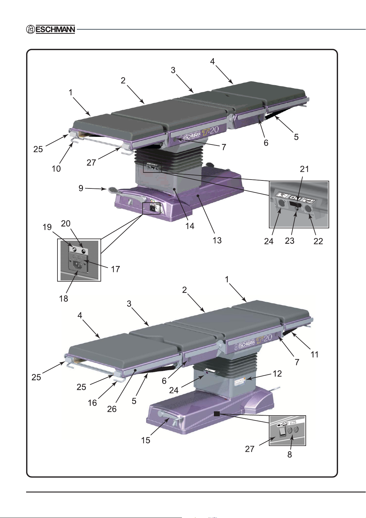
NOTE: The table illustrated has external pedal locking catches. Some
tables have internal locking catches, see section 6.2 and 6.3 for details.
Fig. 1.0 Identification of main parts
P6/54 T-SM47j
Page 7
T20-a
OPERATION TABLE
Key to Fig. 1.0
1 Head section
2 Long trunk section
3 Short trunk section
4 Leg section
5 Leg section gas spring
6 Short trunk section release button
7 Long trunk section release button
8 Battery fuses
9 Wheel foot pedal
10 Head section release bar
11 Head section gas spring
12 Standby control panel
13 Base
14 Pedestal
15 Castor foot pedal
16 Leg section release bar
17 Mains fuses
18 Connection socket for mains (ONLY use Eschmann mains cord, Part No. 391177)
19 Main battery charging state LED:
Red = Mains ‘on’, batteries in ‘bulk’ charge
Amber = Mains ‘on’, batteries in ‘top-up’ charge (duration 2 hours)
Green = Mains ‘on’, batteries in ‘trickle’ charge (i.e. fully charged)
20 Standby battery charging state LED (colour code as main battery above)
21 Main table ‘On/Off’ switch ( = Of f, = On)
22 Connection socket for Eschmann footswitch (ONLY)
23 Table ‘On’ LED (green)
Bright = Table in use, micro-controllers active
Dim = T able ready for instant use but in battery save (sleep) mode
24 Connection socket for Eschmann handset (ONLY)
25 Head and leg section end blocks (use to stow UK handset)
26 Accessory side rails (can also be used to stow handset*)
27 Standby battery switch
* Clip on handset must match side rail type, see ‘Instructions for Use’.
Note: For location of the Serial Number plate see inside front cover.
T -SM47j P7/54
Page 8

2.0 TECHNICAL DATA
2.1 Weights
2.4 Table loading
See maximum patient weight distribution charts in Fig. 2.2
and 2.3 for various table positions and orientations.
The nominal weights of the standard table components
are listed below (for 50mm mattresses):
Leg section (without mattress) .. .. 11.50kg
Leg section mattress .. .. .. .. 2.75kg
Head section (without mattress) .. .. 7.75kg
Head section mattress .. .. .. 2.00kg
T able (base and column only) .. 192.00kg
Long and short trunk assembly* .. 55.75kg
Long and short trunk mattress .. .. 7.25kg
T otal weight standard table .. .. .. 279kg
Lightweight leg section.. .. .. .. 4.50kg
Footrest (incl. mattress) .. .. .. 7.00kg
Width extender (incl. mattress) .. .. 6.00kg
Perineal instrument tray .. .. .. 3.00kg
* (without mattress)
2.2 Dimensions
The following are the nominal major dimensions of the
standard table (with head and leg sections fitted) and
include the 50mm mattress and side rails if applicable (see
Fig. 2.1 for illustration, the number in brackets after the
item details which part):
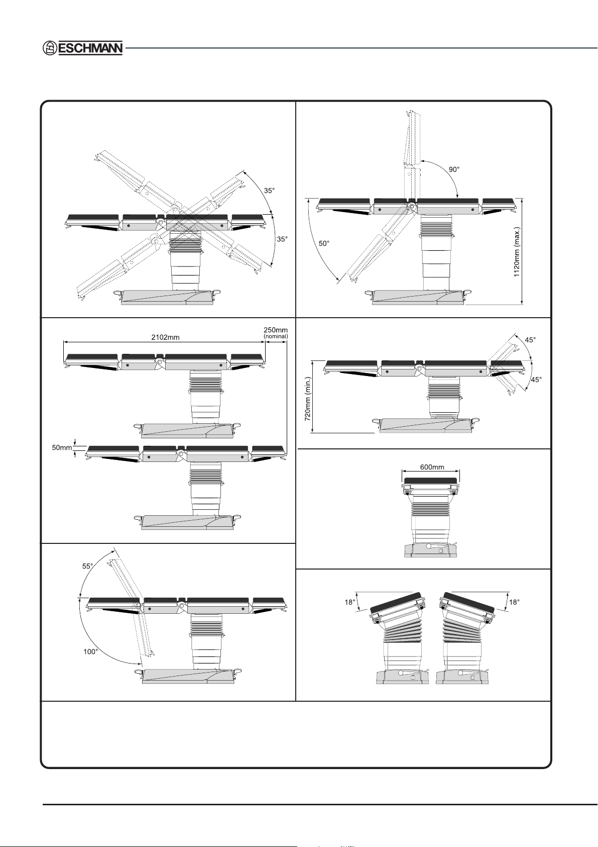
Overall length (2) .. .. .. 2102mm
Maximum height (4) .. .. .. 1120mm*
Minimum height (5) .. .. .. 720mm*
Maximum top traverse (2) .. .. 250mm
Overall width (6) .. .. .. 600mm
Sidebars (Denyer) .. .. .. 37.8 x 5.5mm
* 5mm less for Serial Numbers prefixed T2AA or T2AB
2.3 Movements
Maximum section loading is stated on each item and is
detailed below for reference:
Leg section .. .. 44kg
Head section .. .. 22kg
For accessories the maximum loading is stated on each
item and detailed in the User Handbook supplied with them.
For specific notes on the obese patient see the ‘Instructions
for Use’.
2.5 Electrical
2.5.1 Antistatic requirements
The table has an antistatic pathway from the table top,
through an internal resistor, to the castors.
CAUTION
To complete and maintain the antistatic
pathway the table must be used on an
electrically conductive or antistatic floor and
with mattresses supplied by Eschmann
Equipment.
2.5.2 Batteries
T able base:
Main batteries**:
Two, 12V 10.0Ah, sealed lead acid
Backup batteries**:
Two, 12V 1.2Ah, sealed lead acid
(see battery disposal caution in the ‘Instructions for Use’)
Infrared handset:
Two, 1.5V size AA Alkaline (Note: Must only be
changed in accordance with the notes in the section
6.6.19.2 to ensure the IP rating is not compromised).
The following table movements are maximums and cannot
be assumed to be available in all combinations of table
positioning (see Fig. 2.1 for illustration, the number in
brackets after the item details which part). For example,
with the table in its normal configuration and at minimum
height the maximum Trendelenburg and leg section
movements cannot be achieved due to the proximity of
the floor. Similarly with a large amount of tilt set, maximum
Trendelenburg cannot be achieved.
Max. Trendelenburg (1) .. .. .. 35°
Max. reverse Trendelenburg (1) .. .. 35°
Max. extension (4) .. .. .. .. 230°
Max. flexion (4) .. .. .. .. .. 90°
Head section (5) .. .. .. .. ±45°
Leg section (3) .. .. .. .. -100° +55°
Max. lateral tilt (7) .. .. .. .. ±18°
2.5.3 Internal battery charger**
Input
100-240V a.c. 2.4A (max) 50-60Hz
Output
29.2V d.c. 2A (max.) when charge state LED
red or orange, 27.6V d.c. when charge state
LED green
2.5.4 Fuses
2.5.4.1
Mains input fuses (item 17, Fig. 1.0)
Battery fuses (item 8, Fig. 1.0)
External fuses
2 x T4A (5 x 20mm) 250V
2 x T20A (6.35 x 32mm) 500V
P8/54 T-SM47j
Page 9

T20-a
OPERATION TABLE
Note: The right hand fuse is linked to the main batteries
and the left hand fuse (i.e. nearest to the backup battery
switch) is linked to the backup batteries.
Mains plug fuse
.. .. 10A (type is dependent on plug
which may have been changed from that originally
supplied)
2.5.4.2
Battery fuses** (joining each battery pair)
Internal fuses**
2 x 30A blade type* (1 per battery pair)
(only accessible by engineer)
2.5.5 Duty cycle
This symbol is used to indicate the table’s duty cycle
which, in the worst case, is ‘60s : 600s’, the ratio of the
operating time to the sum of the operating time and the
ensuing interval (see note below). Each motor drive has
its own duty cycle and this is dependent on loading and
table position as detailed below.
Trendelenburg 1 : 4 (60s : 240s) at a maximum torque of
417Nm (e.g. 135kg load offset 31cm from the
fulcrum, or a 300kg load offset 14cm from the
fulcrum. Where this load is the patient and
accessories weight and the offset is how far the loads
centre of gravity is, from the centre of the column).
Traverse 1 : 4 (60s : 240s) when the table is
horizontal and at the maximum load of 300kg, or at
17.5° with a patient weight of 225kg, or at 35° with a
patient weight of 150kg.
Break 1 : 10 (60s : 600s) at maximum patient
weight of 300kg.
Height 1 : 4 (60s : 240s) at maximum patient
weight of 300kg (not offset).
Tilt 1 : 4 (60s : 240s) at maximum patient
weight of 300kg.
Note: The duty cycles above are all for the worst case (i.e.
maximum loads). For reduced loading the above duty
cycles can be increased.
2.7 Use in conjunction with other
equipment
2.7.1 Electrosurgical equipment (h.f.)
The T20-a operation table has been designed to minimise
the possibility of accidental electrosurgery burns and can
be used in conjunction with electrosurgical equipment.
However, contact with any metal surfaces (e.g. table side
bars, or other equipment etc.) can cause burns during
electrosurgery and must be avoided.
2.7.2 Defibrillation equipment
With the mains cord attached the equipment has
defibrillator proof applied parts with type BF protection
against electric shock.
2.7.3 Other
When the T20-a is used in conjunction with other infrared
controlled devices, their controllers should be checked to
ensure that no interference between them and the T20-a is
possible, prior to surgical intervention. Also see the
‘Instructions for Use’.
2.8 Standards compliance
The table has been designed and built to comply with the
following international standards:
BS EN 60601-1: 1990 (issue 2, October 1997)
BS EN 60601-1-2: 1993
BS EN 60601-2-46: 1998
BS EN 60601-1-4: 1997
2.9 Environmental conditions
2.9.1 Operating environment
The table has been designed to operate in the following
environment:
Temperature range .. .. 10°C to +40°C
Pressure range .. .. .. 69KPa to 106KPa.
Humidity range .. .. .. 30% to 75% RH
non-condensing.
2.6 Classification and symbology
All the symbols used on this table are shown and explained
in the ‘Instructions for Use’. These detail the safety category
and class of this table as marked on the table or section by
the use of these symbols.
2.9.2 Transport & storage environment
The table can be transported and stored safely, in the
following environment:
Temperature range .. .. -30°C to +50°C
Pressure range .. .. .. 69KPa to 106KPa
Humidity range .. .. .. 30% to 90% RH
non-condensing.
** NOTE: Items marked ** are to be changed with caution. During change or
replacement they must only be disconnected for a maximum of 60 seconds. If
battery power is removed from the table for longer than this then reconditioning
of the battery management system must be carried out, see section 6.6.26.
T -SM47j P9/54
Page 10
1
4
(see section 2.2)
2
5
(see section 2.2)
6
3
7
These are maximum movements for each aspect, they may not be available in certain combinations (e.g. maximum
tilt and maximum Trendelenburg). Movements that could cause damage cannot be catered for (e.g. position of the
leg section).
Fig. 2.1 Major dimensions and movements
P10/54 T -SM47j
Page 11
T20-a
OPERATION TABLE
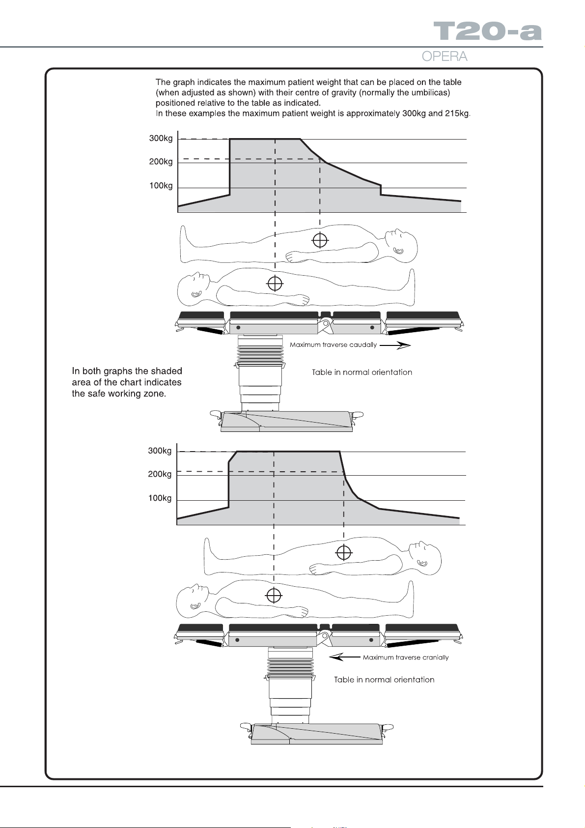
Fig. 2.2 Maximum patient weight v table position graphs
T -SM47j P11/54
Page 12
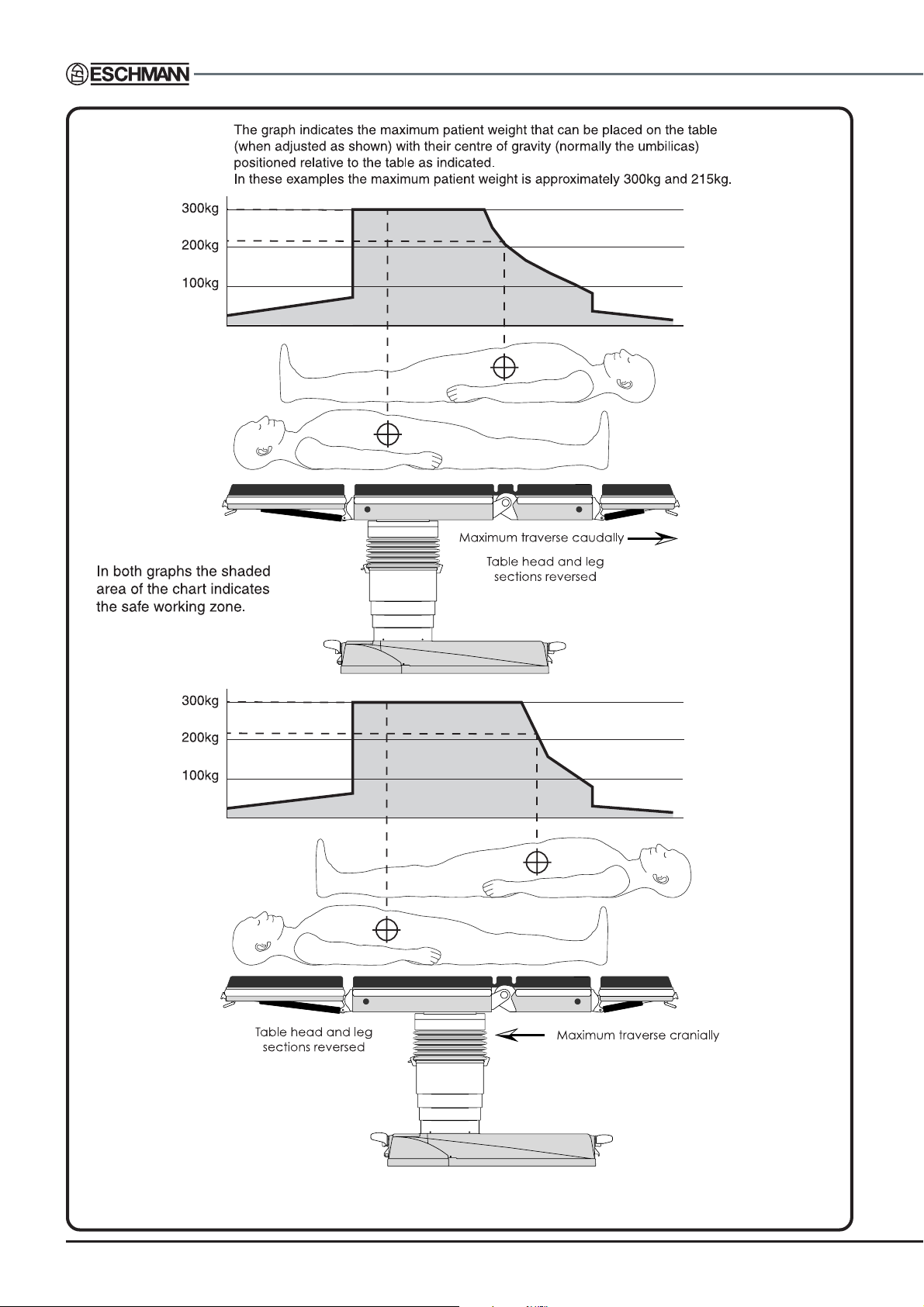
Fig. 2.3 Maximum patient weight v table position graphs
P12/54 T -SM47j
Page 13

T20-a
OPERATION TABLE
3.0 TECHNICAL DESCRIPTION
See Fig. 3.1 and Appendix 3 for schematic diagrams.
3.1 Power supply assembly
This assembly (Part number 111765) which is located in
the table base, has no user serviceable parts and must be
changed as a complete unit. The assembly includes, a
Battery charger loom, a Battery charger module, a Battery
management PCA, a Battery connector loom, a Chassis
plate, two Battery support brackets, a Switch, two Fuses
(32 x 6.35mm 20A ‘T’ type), two Fuse holders, two battery
pairs and all connections, cable ties and screws etc.
3.2 Control electronics
3.2.1 Overview
The control electronics for the T20-a is distributed between
two PCA ’s (the ‘4 actuator PCA ’ and the ‘3 actuator PCA ’).
These two PCA’s contain three distinct microprocessor
daughter PCAs (two on the ‘4 actuator PCA’ and one on
the ‘3 actuator PCA ’).
The ‘4 actuator PCA’ (111524) is located on the column
and includes the ‘main controller’ and the ‘4 actuator
controller’. Each of these ‘controllers’ consists of a
‘microprocessor daughter PCA ’ (1 11526) which have their
control electronics on the ‘4 actuator PCA ’.
The ‘Three actuator PCA’ (111525) is located in the long
trunk section of the table and contains the ‘3 actuator
controller’, another ‘microprocessor daughter PCA’
(1 1 1526) with its control electronics on the ‘Three actuator
PCA’.
3.2.1.1 Microprocessor daughter PCAs
The daughter PCAs consist of a Motorola MC68HC912B32
micro controller, a watchdog circuit, an RS232 line driver
and an SPI UART and RS485 line driver. All the micro
controllers on the T20-a require these components. The
RS232 communications can be used to provide a telemetry
link to custom software running on a PC. Once fitted to
their respective controller boards the micro controllers are
programmed with the appropriate software application.
There is a ‘main controller application’ (110442) and an
‘actuator controller application’ (110443). Both the 4actuator and 3-actuator are programmed with the same
‘actuator controller application’ (110443). A configuration
file is then downloaded to each micro controller that
specifies which controllers are present on which board. It
is possible to configure any actuator to any board, however
the configuration of the electronics is specific to each
actuator.
3.2.1.2 The ‘main controller’
The ‘main controller’ provides the control and supervisory
functions for the table. This consists of the interface to the
infrared handset, corded handset (via RS232), footswitch
and standby panel. It also controls the table power LED.
The main controller communicates with the two actuator
controllers (one of which is co-located on the 4 actuator
PCA) by means of an RS485 multi-drop bus. This system
enables multiple slave controllers to be attached at any
time. The main controller issues a health check poll
message to each of the actuators (up to four of which can
be controlled by the single PCA) to ensure that they are
functioning correctly .
When a command is received from any of the user-input
devices the main controller issues the appropriate
movement commands to the required actuator (or actuator
groups in the case of combined movements).
3.2.1.3 The ‘4 actuator PCA’
The ‘4 actuator PCA ’ is responsible for movement of four
actuators on or within the table’s column. These are the
‘top and bottom height actuators’ inside the column
assembly , the ‘Trendelenburg actuator’ and the ‘Tilt actuator’
mounted on the column. A number of signals control the
movement of each actuator.
A PWM signal is used to set the speed of the motor; digital
signals control direction (forward/reverse), a digital signal
enables the drive circuit and another digital signal effects
a brake on the motor by shorting the windings together.
The electronics provide a digital fault signal to indicate when
there is a problem with the control circuit, or an over current
situation has occurred. An analogue signal is also provided
on all but the ‘bottom height actuator’. The analogue signal
on the top height actuator is the output from a potentiometer
that indicates the combined position of the height actuators.
Although the column contains two motors, there is only a
single potentiometer to indicate the height of the column.
This analogue signal is fed to the ‘top height actuator’; the’
bottom height actuator’ is effectively slaved to the top.
3.2.1.4 The ‘Three actuator PCA’
The ‘Three actuator PCA ’ is responsible for movement of
the three actuators within the tables long and short trunk
sections. These are the ‘left break actuator’, ‘right break
actuator’ and the ‘traverse actuator’. These actuators are
controlled by the same signals as on the ‘4 actuator PCA ’.
In terms of feedback, both the ‘left and right break actuators’
have potentiometers and the ‘traverse actuator’ has limit
switches which open when the long trunk reaches either
end of its movement. The ‘left and right break actuators’
are independently controlled to move at a set speed and
to maintain a minimum deviation between them.
T -SM47j P13/54
Page 14

3.2.2 Handset overview
There are two versions of handset, a cordless type (infrared
handset) with an infrared emitter powered by 2 AA cells
and a corded version (corded handset) with an RS232 link
to the main processor on the ‘4 actuator PCA’. The latter
version derives its power from the T20-a.
3.2.2.1 Infrared handset
The 4 x 5 matrix keyboard is decoded using a proprietary
keyboard decoder. This device is powered down and
remains dormant until a key is pressed causing its clock
oscillator to be initialised. The key is decoded and the 38kHz
modulated signal is fed to the infrared LED via a FET . The
whole system is powered via 2 AA batteries
3.2.2.2 Corded handset
The 4 x 5 matrix keyboard is decoded using a proprietary
keyboard decoder. This device is powered down and
remains dormant until a key is pressed causing its clock
oscillator to be initialised. The key is decoded and the 38kHz
modulated signal is fed to a PIC processor. The processor
decodes the output from the keyboard decoder into RS232.
This output is fed to an RS232 line driver. The corded
handset’s power is supplied directly from the T20-a, 5V
power supply . The handset contains a DC-DC converter to
supply 3.3V for the keyboard decoder. There are indicator
LED’s to show the charge status of the table batteries (main
and standby).
P14/54 T -SM47j
Page 15
T20-a
OPERATION TABLE
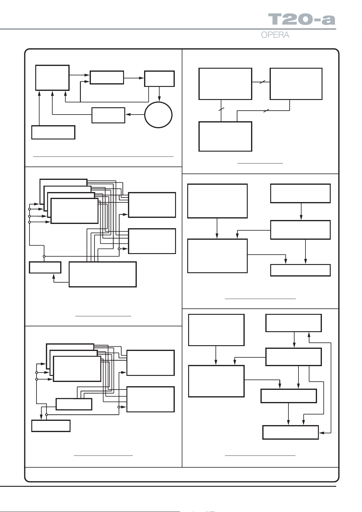
PROCESSOR
CONTROL
CONTROL FROM
HOST MICRO
FET DRIVERS
POSITIONAL
FEEDBACK
OVER
CURRENT
MANAGER
MOTOR
Basic control and feedback - all actuator drivers
AXIS TILT
AXIS TREND
AXIS HEIGHT 1
AXIS HEIGHT 2
POSITION ENCODERS AND
ANCILLARIES
OVER CURRENT MANAGERS
PROCESSOR COMMUNICATIONS
44
CONNECTOR 64 WAY
INTERFACE
12
4
Processor PCA
BatteryKeyboard
Power Management
Keyboard Encoder
POWER
MANAGEMENT
AXIS BREAK RIGHT
AXIS BREAK RIGHT
AXIS TRAVERSE
POWER
MANAGEMENT
CONNECTORS
INC:
CONNECTORS & INTERFACES
MICRO CONNECTORS
Four Actuator PCA
CONNECTORS
POSITION
MONITORS
OVER CURRENT
MANAGERS
Infrared Driver / Emitter
Handset remote version
Connector/LeadKeyboard
Power Management
Keyboard Encoder
Processor
RS232 Decoder/Driver
Three actuator PCA
Handset corded version
Fig. 3.1 Schematic diagrams
T -SM47j P15/54
Page 16

4.0 SAFETY WARNINGS
4.1 ‘Service position’
When the four M10 screws (each side) that secure the
trunk sections to the pedestal are removed, to place the
table in the ‘Service position’ as detailed in section 1.9,
always take extreme care (and ensure table is switched
‘off’ before tilting top into or out off the ‘Service position’).
When the M10 screws are removed the table trunk sections
may tilt dramatically unless the sections are fully supported
during screw removal. Always lower the trunk sections into
(and out of) the ‘Service position’ slowly and always return
the table trunk sections to the ‘normal’ position (taking care
not to trap fingers) as soon as possible, replacing the eight
M10 screws securely. Also remove the following before
placing the table into the ‘Service position’:
Head section Leg section
Trunk mattress All accessories
When powering the table in the ‘Service position’ using
tool T2203 (to connect the table top connector blocks)
extreme care should be taken and powering the table in
this position should be limited to essential testing only . It is
preferable to return the table out of the ‘Service position’
before powering the table.
4.2 Lifting
During some of the procedures detailed in this manual it is
necessary to lift heavy assemblies. These are the long and
short trunk assembly, the wrapround assembly and the
telescopic assembly. These all require two people to lift
safely and any procedure that requires these to be removed
from the table should not be attempted if two people are
not available. Other components although not heavy
enough to require two people, should be handled using
the correct lifting techniques to minimise personnel injury .
It is advised that suitable protective footwear is worn when
handling heavy parts.
4.3 M10 trunk screw removal
When removing the four M10 (hexagonal head) screws
that secure the trunk sections to the column, always ensure
that precautions similar to those detailed in 4.1 above are
taken. Remove all accessories, sections and trunk mattress
and support the trunk sections during screw removal.
4.4 Trend and tilt actuator removal
When the Trend and /or tilt actuators are removed the trunk
sections will not be stable. Before removal follow similar
precautions to those detailed in section 4.1. Remove all
accessories, sections and trunk mattress and support the
trunk sections during actuator removal. Replace the
actuator as soon as possible.
4.5 Working with mains voltage
The only time that it may be required to work with mains
voltage applied to the table is whilst testing the battery
charger. During this procedure ensure that normal safe
working procedures are employed for an activity that entails
working with mains voltage, such as:
i Reduce the amount of live work to the minimum
possible.
ii Use common sense and stop working if
approached, distractions can kill.
iii Ensure the area is clear of all unnecessary
personnel or warn people in the area to stay
clear during live work. Also ensure that you are
not entirely alone and that someone could come
to your assistance if you should suffer an electric
shock.
iv Only use the correct equipment, probes and
cables for the work in hand.
v Mains power should be supplied via an RCD
(residual current device).
vi Turn of f the mains power whenever possible to
reduce risks.
4.6 Gas springs
When removing or servicing the table head and leg sections
gas springs refer to the warning in section 6.5.1.2. They
do not require lubrication and do not attempt to open them.
Also note the disposal notes provided in 6.5.1.2 (vii).
4.7 Hot parts on PCAs
During service and when covers are removed note that
parts of the PCAs can become hot enough to cause burns.
Beware that touching these assemblies when hot could
result in unexpected body movements.
4.8 Biological contamination
During servicing of the table it is advised that protective
gloves should be warn to avoid biological contamination. It
is preferable that the table be cleaned and disinfected
before service.
4.9 Connection of leads
When connecting test leads to the table during service
ensure that these do not constitute a tripping hazard.
4.10 Leaking batteries
In the unlikely event of a battery leaking in the table base
avoid spreading the contamination (sulphuric acid) and:
i Wear suitable personnel protection (goggles, gloves
etc.) do not smoke and avoid sparks.
ii Use a bonding agent such as sand, or sodium
carbonate to absorb and neutralise the bulk of the
electrolyte. Wash (and rinse well) the contaminated
area with water, taking care not to splash electronics
or any other table base components.
iii Do not flush electrolyte into the sewer system but
dispose of the used bonding agent and all cleaning
materials in accordance with local waste regulations.
In the case of skin contact wash and rinse immediately
with water. If splashed into eyes rinse well with water and
seek medical advice. If acid mist is inhaled, inhale fresh
air and seek medical advice.
P16/54 T -SM47j
Page 17

T20-a
OPERATION TABLE
5.0 MAINTENANCE
5.1 Power supply assembly
This assembly (Part number 111765) which is located in
the table base, has no user serviceable parts and must be
changed as a complete unit (also see section 3.1).
5.2 T able fault finding
5.2.1 The ‘Instructions for use’ contains a basic fault finding
table that can be used to solve any minor problems. This
covers the main user errors (i.e. there is no fault) that can
occur when the user has not read and understood the
‘Instructions for use’. It also contains the first line of fault
finding (i.e. check external fuses, try another handset, try
another mains lead). The following section (5.2.2) provides
a test sequence to help determine the fault (for the majority
of faults that may occur) that could stop the table responding
to an input via a control device. Mechanical faults are
normally self evident in that a part is worn, damaged or
broken. In this case refer to the appropriate section of this
manual for part replacement information. Appendix 3
provides the schematic diagrammes that can also be used
in fault finding.
5.2.2 Follow the sequence below to identify most major
faults that result in a lack of response to a control command:
1 When the table is initially switched ‘on’ is the table
‘on’ LED (item 23 of Fig. 1.0) bright, dull or ‘off’ for
the first few seconds.
If dull turn the table ‘off’ wait at least 10 seconds
and then turn back on. If the LED is still dull or
‘off’ this indicates an electronics fault see 5.2.3.
If bright move to 2 below.
If it is flashing this also indicates an electronics
fault see 5.2.3.
2 Try the ‘standby control panel’ (any motion except
Trendelenburg), if this fails try the ‘standby control
panel’ with the backup battery switch depressed.
If the table works from the ‘standby control panel’
this indicates a fault with the control device or
its connection to the table.
If the table works from the ‘standby control panel’
only when the backup battery switch is pressed
this indicates a fault with the main batteries
(replace the whole Power supply unit).
Now try Trendelenburg from the ‘standby control
panel’, if this and only this motion works it indicates
a problem with the main control PCA.
3 If one of the motor groups ‘only’ has failed then this
indicates a problem with its associated PCA as follows:
Break and traverse - Three actuator PCA
Tilt, T rend and Height - 4 Actuator PCA
This distinction may help in reducing the amount of
diagnostics and cover removal.
4 Remove covers and check battery fuses (see
section 5.3.1 and 6.6.26). Also look to see if the
PCA indicator lights are flashing ‘on’ for 1 second
and ‘off’ for 1 second. If they are ‘off’ or flashing
faster, this indicates an electronics fault see 5.2.3.
5 If the fault is only apparent for one motion this could
indicate a failed motor or failed sensor for that motion,
or, an electronics fault. If the motion starts and then
stops immediately this could indicate a failed sensor
or an over current situation. Test motor (as detailed
in section 6.6), if the motor works and no small
movement is observed following a demand for that
motion, it indicates an electronics fault, see 5.2.3.
5.2.3 Electronic faults can only be determined with the
table connected to a PC with the ‘T20 Application Software’
installed. Consult the Application Software Manual (as
detailed in section 1.1) which provides guidance on fault
diagnosis. Also note that when correcting electronic faults
(and following some parts replacement) the table will require
reprogramming, reconfiguring or recalibration. These aspects
are also fully covered in the Application Software Manual.
5.2.4 Break motion control
5.2.4.1 The two break arms are independently controlled
and are synchronised to operate within a programmed limit
of each other. This control system can result in small
variances that appear as a slight misalignment, this is
acceptable and a part of the normal table control software
routine. In the unlikely event that this deviation goes outside
of the programmed limit the table break motion (only) will
stop working. This can sometimes be corrected as below .
5.2.4.2 Whilst observing the two break arms press (for
approximately 0.5 seconds only) a break control button on
the handset (B7 or B8 of Fig. 6.9) once or twice. If this
makes the deviation worse press the other break control
button as above once or twice. If the break motion still
does not work correctly after this there could be a fault in
one of the following:
Break motor
Break potentiometer
Wiring to any of the above
Significant uneven table loading*
*This problem will only be evident during use and if
investigated at service it will be difficult to reproduce.
5.2.5 Trunk section connector blocks
5.2.5.1 If all the top table functions stop working (e.g. break
and traverse) the connector blocks (item 5, Fig. 6.7 and item
14, Fig 6.3) could be failing to connect correctly due to
contamination etc. Check that a good contact is being made
between the column and trunks connector blocks.
5.3 Fuse location
5.3.1 All fuse locations are identified in section 2.5.4 and
Fig. 1.0. DO NOT REMOVE OR CHANGE INLINE BA TTERY
FUSES UNLESS YOU HA VE READ SECTION 6.6.26.
T -SM47j P17/54
Page 18

5.4 Service schedule and safety check
This should be performed every 6 months to ensure the
continued safe operation of the table.
NOTES:
1. The numbers in brackets in this schedule details the
section of this manual that should be referred to when
performing or checking the activity detailed.
2. Prior to service operate all table functions (6.7) to
ensure correct operation, note any problems for
investigation during the service.
3. Remove base covers as required (6.2.2.1). Access
can be gained to the lower, lower-mid, upper-mid and
top of the column (6.2.3.2 to 6.2.3.5). If necessary the
telescopic covers can be removed (6.2.4.1).
4. Prior to changing a motor check it has failed and that
the fault is not in the control electronics (6.6.6 - 6.6.9).
5. In the sections below where the word ‘check’ is used
it is inferred that if the check reveals a fault then this
should be corrected.
6. Tilt tabletop into service position as required (1.9) but
note safety warning, section 4.1.
7. The right-hand column should be used to tick off each
item of the schedule on completion and to note parts
replaced (or wearing that will soon need replacing).
8. This schedule should be photocopied and completed,
copies to be retained by the engineer conducting the
service and the person responsible for the table.
Base and column:
1. Check pedal dampers for wear or leaking (6.3.3).
2. Disassemble, clean and lubricate the two fixed wheel assemblies and the four
castor assemblies (6.3.4, 6.3.5). Test resistor assembly as 6.3.5.1 (viii).
3. Check brake pads for wear, damage, or hard and brittle (6.3.6).
4. Check the castor pillar and pedal spindle bushes for wear (6.3.7 and 6.3.8).
5. Check and lubricate both lifting roller assemblies (6.3.9).
6. Check for wear of both pedal catch mechanisms (6.3.12) and renew the antislip pad on both pedals (6.3.11).
7. Check security of all fixing screws, nuts and retaining clips within the base area
and check the pedal operation works smoothly and correctly .
8. Check main and standby battery voltage (standby and load) as 6.3.2.(iia). Check
security , connectors and loom routing of PSU.
9. Check the Trendelenburg, tilt and telescopic column actuator assemblies for
excessive wear or failure (6.4.2, 6.4.3, 6.4.4 and 6.4.5) and grease worm and
wheel on Trendelenburg and tilt motor assemblies.
10. Check the security and positioning of all wiring looms and connections. Add
cable ties, reposition or replace as necessary .
11. Check switch and fuse panels for operation and signs of damage (6.6.16).
12. Check for wear or damage to the tilt and Trendelenburg bushes in the trend
and tilt frame (6.4.6 and 6.4.7). Check all fixing screws within the inner and
outer (tilt and Trend) gimbal assemblies.
13. Check the wraparound aligning bearing pads, adjust as required to remove play
or replace (6.4.8).
14. Check height potentiometer is secure to the wrapround and that the cable is in
good condition and secure to the base (6.6.13).
15. Check the security and the routing of the 4 actuator PCA, connectors, energy
chains and all looms within the column. Cable-tie if necessary
16. Remove and replace bellows if split/damaged (6.2.5).
17. Check the security and the routing of the Three actuator PCA, connectors,
energy chains and traverse and break motor looms within the traverse housing.
Cable-tie if necessary .
18. Check that traverse motor and traverse belt tensioners are secure to the support
plate and lubricate tensioner bearings between screw and bearing only . Check
traverse motor (6.5.2.1) and adjustment of the traverse belt tensioners’ (6.5.2.2).
19. Check the condition and lubricate if necessary the drive belt guide needle
bearings between screw and bearing only (6.5.2.9).
P18/54 T -SM47j
Page 19

Trunk sections and covers.
20. Check condition (excessive wear/breakage) of traverse rod bearings (6.5.2.8).
21. Check operation and adjustment of the traverse limit switch assemblies’ (6.6.14).
NOTE: Check that the traverse movement stops when the traverse limit switch
pin is depressed from both ends and from both sides of the table.
22. Check that the set screws that retain the traverse leadscrews are tight (20Nm)
and lubricate the lead screw and traverse rod.
23. Clean the male and female pins on the 4-way communication connector block
to ensure a good contact, check for cracks or damage (6.6.15).
24. Remove long / short trunk push button assemblies, clean and check condition
of catch blade (6.5.2.7), do not lubricate.
25. Check guide pin holes (in the attachment blocks) for excessive wear (6.5.2.10)
26. Checks for equal and even movement of the two break motors (i.e. check both
break arms in the short trunk move up and down together). If required, replace,
adjust or recalibrate (6.5.2.3 and 6.5.2.4).
27. Service infrared handset (6.6.23). Check function and condition of corded handset.
28. Check that all side rail fixing screws are tight in the long and short trunk sections
(21Nm) and the head and leg sections (15Nm).
29. Check the condition of the trunk section covers (6.5.2.6 and 6.5.1.3).
30. Ensure tabletop is not in the service position and the locking screws are replaced
to lock the trunk sections out of the service position.
31. Ensure free movement of the telescopic covers. Check condition and function
of Standby control panel, replace if adhesion to column cover shows any sign
of failure (6.6.25).
32. Ensure the base covers are refitted (6.2.2.2).
33. Conduct the function tests (6.7) correct any faults and conduct the function
tests again until all functions are working correctly .
T20-a
OPERATION TABLE
Head and leg sections.
34. Check all guide pins for wear or damage (6.5.1.1).
35. Check gas springs for leaks or poor performance (6.5.1.2).
36. Check gas spring pivot pins and shoulder screws for security and wear (6.5.1.4)
36. Check the condition of the head and leg section covers (6.5.2.6 and 6.5.1.3).
Ensure the ‘Electrical safety checks’ have been carried out (see Appendix 4 of the ‘Service Manual’).
Leave table clean and in a fully functioning condition with batteries on charge and table switched off.
Service / T able details
Service Engineer
Engineers Name (Eschmann / Hospital*)....................................................................Contact T el. No. ...........................................
Person responsible for table
Name....................................................... Position ...............................................Dept. ............................................
Hospital ................................................... Health Authority ..................................Tel.No...........................................
T able details
T able SN.................................................. Location ..............................................Account No. (If appl.) .............................
Service detail
Date......................................................... Time completed ..................................2nd visit reqd. YES /NO*
(* Delete as required)
T -SM47j P19/54
Page 20

6.0 PART REMOVAL/ADJUSTMENT/
REPLACEMENT
6.1 GENERAL
6.1.1 This section has been split into the following sections
for easy reference, note safety warnings in section 4.0:
6.2 Table base and column covers
6.3 Table base components
6.4 Table column components
6.5 Table sections
6.6 Electrical components
6.7 Function tests after maintenance
6.8 Accessories
6.1.2 Within the text detailing a part replacement any
specific setting or adjustment is fully detailed. Each section
also provides specific details of any required lubrication
during assembly, the use of threadlock fluids and any
specific torque settings that should be adhered to.
Note: Conversion chart and conversion data for Torque
values in Appendix 1.
6.1.3 All replacement parts must be supplied by
Eschmann and note that this also includes all the nuts,
screws, roll pins, pivot pins etc. that are specified in the
‘Illustrated parts list’. Some of these are provided to a
specific standard (e.g. high tensile) and the use of ‘similar’
items could compromise the strength and therefore the
safety of the table.
6.1.4 All electrical components are non-repairable and
must be replaced with new Eschmann parts only, to
maintain the safety of the system. Replacement is usually
a self-evident procedure but ensure :
i Good wiring practice is observed and static
discharge procedures are adopted as applicable
when handling PCAs (printed circuit assemblies).
ii All wiring is replaced as found and secured away
from any moving parts using adequate quantities of
cable clips and restraints.
iii All fixings are replaced as found and no substitutes
are used.
iv The function checks detailed in this manual (section
6.7) are carried out on completion of any part
replacement.
6.1.5 After all procedures the table should be left clean
and in full working order (run function test detailed in 6.7)
to ensure safety and ensure the (Electrical safety checks)
in Appendix 4.
6.1.6 Before any part removal/replacement procedure
ensure the table is not connected to the mains. If mains
power is required at any time during diagnostic checks
ensure that appropriate safe working procedures for live
working are adopted (see section 4.5).
6.1.7 T o avoid duplication of common procedures a cross
reference to the required part of the manual detailing the
procedure is provided where required. Note these sections
also contain assembly notes that must be followed.
6.1.8 All part numbers can be found in the Illustrated parts
list (Publication number T -IPL35 available from Eschmann
Equipment at the address on the inside of the front cover).
This Illustrated parts list should be available for reference
during part removal or replacement.
6.1.9 The locking catch for foot pedals can be external or
internal. Please check which type is fitted to the table and
follow the appropriate notes in the sections that follow. The
external catch is shown in Fig. 6.2a, item 20 and the internal
catch is shown in Fig. 6.2b, item 6.
5.1.9 Tables with a Serial Number prefix T2AC or later
have been increased in height by 5mm. Check that the
correct parts are fitted by referring to the Illustrated parts
list. Fig. 6.2b and Fig. 6.2c shown both configurations.
6.2 TABLE BASE & COLUMN COVERS
6.2.1 The removal, replacement and method of gaining
access behind the table covers, has been split into the
following sections for easy reference:
6.2.2 Base covers.
6.2.3 Access to column.
6.2.4 T elescopic covers.
6.2.5 Bellows.
For reference Fig. 6.1 shows the general arrangement of
all the cover components.
6.2.2 Base covers
CAUTION
Ensure the cable to both of the infrared PCA’s
are released before sliding the base covers
away from the base, see ‘v’ below.
6.2.2.1 Removal of base covers.
i Raise the height of the tabletop sufficiently to expose
the screws at the lower edge of the lowest telescopic
section where it joins the base covers.
ii Remove both foot pedals by releasing their retaining
screws, taking care not to loose the return spring
(spring only fitted if the pedal has an external catch).
iii Remove the button head screw from the end of the
long base cover and the countersunk screw from both
sides of the covers where they join at their lower edge.
iv Remove the two screws from the lower edge of each
side of the lowest telescopic cover (not the end face
screws).
Note: These screws differ in length and must be put
back as found (short 12mm to short trunk end, long
15mm to long trunk end).
P20/54 T-SM47j
Page 21

T20-a
OPERATION TABLE
v Raise the telescopic covers sufficiently to clear the
base covers and slide the base covers away from
the pedestal column taking care to release the cable
connected to the infrared receiver PCA fitted below
each base cover section. The cable plug is released
by pressing the moulded release catch.
vi Continue to slide the base covers away from the
table until clear and place them safe until replaced.
6.2.2.2 Replacing base covers.
i Slide the base covers into a suitable position to enable
the two infrared receiver leads to be reconnected to
the PCA fitted to each cover section, ensuring the
plug snaps into place correctly. Check both the
receivers are working by covering each in turn and
send a control command via an infrared handset.
ii Raise the telescopic cover sufficiently to enable the
covers to be correctly positioned and aligned.
iii Replace all the fixing screws (without threadlock)
and the earth equalization pin using threadlock (part
number 670650).
iv Replace and secure the foot pedals (see note below)
ensuring they are placed at their correct ends (long
pedal at head end) with the internal return spring in
place (spring only fitted if the pedal has an external
catch). Use threadlock (part number 670650) on
both screws.
Note: When replacing the foot pedal shoulder screw
(on pedals with internal spring return) initially tighten
with fingers to ensure that the shoulder of the screw
has correctly located into the hole in the shaft.
v T est table base functions.
6.2.3 Access to column.
6.2.3.1 Access can be gained behind the column covers
in four ways. Either, release the bottom of the telescopic
covers and lift them to gain access to the lower column
(see section 6.2.3.2), or release the top of the telescopic
covers and lower them to gain access to the lower-mid
column (see section 6.2.3.3), or release the bottom of the
bellows and raise them to gain access to the upper-mid
column (see section 6.2.3.4), or release the top of the
bellows and lower them to gain access to the top of the
column (see section 6.2.3.5).
6.2.3.2 Lower column access
i Raise the height of the tabletop as far as possible,
this will ensure maximum access and expose the
screws at the lower edge of the lowest telescopic
section where it joins the base covers.
ii Remove the two screws from the lower edge of each
side of the lowest telescopic cover (not the end face
screws).
Note: These screws differ in length and must be put
back as found (short 12mm to short trunk end, long
15mm to long trunk end).
iii Raise the telescopic covers to gain access to the
lower part of the column.
iv On completion of work on the lower column replace
the four lower retaining screws to secure the
telescopic covers to the base.
v T est that the telescopic covers function correctly by
powering the table between maximum and minimum
height several times.
6.2.3.3 Lower-mid column access
CAUTION
Ensure the cable to the standby control panel
and the earth wire is released before lowering
the telescopic covers, see ‘iii’ and ‘iv’ below.
i Remove fourteen plastic rivets (see inset of Fig. 6.1
for details) around the lower edge of the bellows.
ii Lift the bellows to the left and right of the accessory
and switch panels (items 8 and 9 of Fig. 6.1) and
remove the four screws securing the top edge of
the upper telescopic cover to the telescopic cover
support brackets (item 6 of Fig. 6.1).
iii Lower the telescopic covers slowly until sufficient
access has been gained behind them to allow
disconnection of the ribbon cable from the standby
control panel where it connects onto the column PCA.
iv Continue to lower the telescopic covers and if
required (i.e. if table is near maximum height)
disconnect the earth wire from the middle telescopic
cover where it is connected to the wrap round.
v On completion of work on the lower-mid column,
replace the column covers in the reverse of the
sequence above, check the electrical connections
have been made correctly during assembly. Use
threadlock (part number 670650) on all screws.
vi Test the telescopic covers and standby panel
function correctly by powering table between
maximum and minimum height several times and
testing other standby buttons.
6.2.3.4 Upper-mid column access
i Remove fourteen plastic rivets (see inset of Fig. 6.1
for details) around the lower edge of the bellows.
ii Lift the bellows to the left and right of the accessory
and switch panels (items 8 and 9 of Fig. 6.1) and
remove the two screws securing each switch panel
retainer (item 7 of Fig. 6.1) to the telescopic cover
support brackets (item 6 of Fig. 6.1).
iii The bellows can now be raised but take care not to
lift then too far without disconnecting the loom
connections from the switch panels where they
connect to the column PCA.
iv On completion of work on the upper-mid column,
replace the column covers in the reverse of above
sequence, check that the electrical connections have
been remade correctly during assembly. Use
threadlock (part number 670650) on all screws.
T-SM47j P21/54
Page 22

AB C
Bellows rivet removal/replacement detail
To remove rivets :
a) Pull up plunger head (see B), do not damage rivet head.
b) Pull rivet out of cover (see A).
To replace rivets :
a) Align holes in cover sections (see A).
b) Place rivet in hole so that shoulder of rivet shaft is flush
with outer cover face (see B).
c) Press rivet plunger head until flush (see C).
Fig. 6.1 Table covers general arrangement
P22/54 T-SM47j
Page 23

T20-a
OPERATION TABLE
v T est that the bellows work correctly by moving table
through several complete sequences of extreme tilt
and Trendelenburg (use handset not standby panel).
6.2.3.5 Top of column access
i Remove the steel covers (items 12, 13 and 14 of
Fig. 6.1) surrounding the top of the bellows (two
screws per side cover, three screws per end cover).
ii Remove twelve screws holding the four top bellow
clamping strips (item 10 of Fig. 6.1) in place. This
will release the top of the bellows allowing them to
be lowered gaining access to the top of the column.
iii On completion of work on the top of the column,
replacing the bellows and steel covers in the reverse
of the sequence above, checking that the bellows
have been correctly positioned in their top and
bottom clamps. Use threadlock (part number
670650) on all screws.
vii T est that the bellows work correctly by moving table
through several complete sequences of extreme tilt
and Trendelenburg movements (use handset not
standby panel).
vii Remove the four screws (two per join) holding the
top telescopic section together and remove the
section. Continue removing the top telescopic
section (disconnecting the earth link as required)
until all sections have been removed. Note
orientation of parts for later assembly .
6.2.4.2 Refitting the telescopic covers
i Ensure the plastic scratch and noise reducers are
in place on the lower and upper edges of each
telescopic section before starting to refit them.
ii Refit the covers by reversing the removal sequence
detailed above, checking that the earth connections
and the standby control panel are reconnected. Use
threadlock (part number 670650) on all screws.
iii On completion, test that the telescopic covers move
correctly, by powering tabletop (use handset not
standby panel) up and down from minimum to
maximum several times. Check bellows work
correctly by moving table through several complete
sequences of extreme tilt and Trendelenburg
movements. Then check all the functions of the
standby panel
6.2.4 Telescopic covers
6.2.4.1 Removal of telescopic covers
CAUTION
Ensure the ribbon cable from the standby
control panel and the earth wire are released
during removal of covers, see ‘v and vii’ below .
To remove the telescopic covers completely from the
column proceed as follows, but note that access to the
column can be gained by releasing the telescopic covers
not removing them (see sections 6.2.3.2 and 6.2.3.3):
i Raise the height of the tabletop sufficiently to expose
the screws at the lower edge of the lowest telescopic
section where it joins the base covers.
ii Remove the two screws from lower edge of each
side of the lowest telescopic cover (not the end face
screws). See note in 6.2.3.2 (ii).
iii Remove fourteen plastic rivets (see inset of Fig. 6.1
for details) around the lower edge of the bellows.
iv Lift the bellows to the left and right of the accessory
and switch panels (items 8 and 9 of Fig. 6.1) and
remove the four screws securing the top edge of
the upper telescopic cover to the telescopic cover
support brackets (item 6 of Fig. 6.1).
v Lower the telescopic covers slowly until sufficient
access has been gained behind them to allow
disconnection of the standby control panel ribbon
cable from its connection on the column PCA.
vi Continue to lower the telescopic covers and
disconnect the earth wire from the middle telescopic
cover where it is connected to the wrap round.
6.2.5 Bellows
WARNING
Removal and replacement of the bellows entails
removal of the trunk sections, which are heavy
and require two people to lift safely.
6.2.5.1 Removal of the bellows
T o remove the bellows completely proceed as follows, but
note that access to the column can be gained by releasing
the telescopic covers and bellows without removing them
(as detailed in section 6.2.3):
i Remove as much as possible from the tabletop
including all sections fitted to the two trunk sections
and the mattress.
ii Release the top of the bellows as detailed in section
6.2.3.5, points ‘i-ii’.
iii Release the bottom of the bellows as detailed in
section 6.2.3.4, points ‘i-ii’.
iv Reach inside the bellows and remove the four
screws (two per panel) securing the switch panel
retainers (item 7 of Fig. 6.1) to the accessory panel
and the switch panel (items 8 and 9 of Fig. 6.1). The
switch panel retainers can now be removed.
v Remove the trunk sections (see note below) together
with the traversing and break mechanisms by
removing the four screws that secure this assembly
to the top of the pedestal (two M10 hexagonal head
screws underneath each side). Carefully place the
trunk sections to one side, leaving them in a stable
position not resting on any fragile components.
T-SM47j P23/54
Page 24

Note: The trunk sections may become unstable
when the M10 screws are removed and extreme
care should be taken. Ensure trunks sections are
supported during removal of these screws.
vi Remove the two top location angles (item 15 of Fig.
6.3) and carefully remove the bellows by lifting them
up and off the top of the column.
6.2.5.2 Replacing the bellows
Replace the bellows by reversing the removal sequence
ensuring that the trunk sections are replaced in the correct
orientation (short trunk section at leg end). Note that the
four M10 fixings screws should be tightened to a torque
setting of 48Nm. Also ensure that the sprung electrical
contact pins on the underside of the long trunk section are
not damaged, use threadlock (part number 670650) on all
screws (except those securing the switch panel and the
accessory panel). Check that the bellows have been
correctly positioned in their top and bottom retainers and
that they work correctly by moving table (use handset not
standby panel) through several complete sequences of
extreme tilt and Trendelenburg movements. Test that the
telescopic covers move correctly, by powering the tabletop
up and down from minimum to maximum several times.
6.3 TABLE BASE COMPONENTS
6.3.1 The following parts on the table base may need
replacement in the event of wear, damage, or malfunction,
(see notes in each section) for the Power supply assembly
see section 6.6.5. The procedures for these are detailed
in the following sections:
6.3.2 Batteries
6.3.3 Pedal dampers
6.3.4 Front wheels
6.3.5 Castors
6.3.6 Brake pads
6.3.7 Castor pillar bushes
6.3.8 Pedal spindle bushes
6.3.9 Lifting roller assembly
6.3.10 Pedal catch block
6.3.11 Pedal anti-skid pads
6.3.12 Pedal catch pawl and spring
Fig. 6.2a shows the general arrangement for a table with
external pedal catches and Fig. 6.2b and Fig. 6.2c show
the general arrangement for a table with internal pedal
catches (Fig. 6.2c shows the new base arrangement for
tables having a Serial number prefix of T2AC or later).
These figures identify the main parts of the table base
assembly, refer to them as required. Ensure you refer to
the correct instructions according to the type of pedal catch
fitted to the table (also see section 6.1.9) and base
arragemnet according to table height. Always ensure the
correct parts are used during part replacement, refer to
the illustrated Parts list.
6.3.2 Batteries
IMPORT ANT NOTE:
See section 6.6.26 (battery management system
reconditioning) before changing the batteries.
i Check fuses in the event of power failure before
replacing batteries (before removing or replacing
either battery inline fuse see section 6.6.26).
ii Ensure the table is switched ‘off’ at the main column
switch. If batteries are suspect do not change a them
unless they are obviously faulty using the following
notes as a guide.
a) The fully charged (single) battery voltage should
be at least 12.5V (or a series voltage of 25-27.5V
per pair) and a series voltage of between 23.5V
and 25.5V when powering the tilt motor (table
not loaded). To test the standby batteries press
and hold the standby battery switch whilst
operating the tilt motor via a handset.
b) Each battery within a pair should be at the same
voltage (i.e. within 0.5V of each other).
c) If the voltage of one battery is significantly lower
than the other (> 2V) change the Power supply
assembly .
iii When changing batteries always change them as a
pair (main or standby). Disconnect them at the inline
connector on the top of each battery .
iv Replace covers, if required recondition the battery
management system (see section 6.6.26) and check
table functions.
6.3.3 Pedal dampers.
To replace a pedal damper if operation of the associated
pedal shows sign of unit failure (pedal operation not
damped), or oil is visible during inspection of the base
during maintenance, refer to Fig. 6.2a or 6.2b as
appropriate and proceed as follows.
i Ensure both pedals are in the raised position.
ii Remove the appropriate base cover as detailed in
section 6.2.2.1.
iii To gain easier access for this procedure remove
the damper angle bracket from the table base plate
by removing its two retaining screws. This will enable
the damper to be swung out and up clear of its low
position making removal of the pivot pins easier.
iv Note the orientation of the spring clip on the piston
pivot pins, this is critical and must be copied when
replacing them (the limb of the clip should rest
against the pedal anchor block to stop any lateral
movement of the pedal assembly). Remove both
the pivot pins and the faulty damper.
v Replace the damper with a new unit (piston end to
the pedal anchor block end not the damper angle
bracket end). When replacing pivot pins apply grease
(part number 110477) and ensure the piston spring
clip is in the correct orientation as noted in ‘iv’ above.
P24/54 T-SM47j
Page 25

T20-a
OPERATION TABLE
vi Compress or extend the damper length manually to
enable the damper angle bracket to be secured back
onto the base plate using threadlock (part number
670650) on the screw threads.
vii Reassemble table by reversing the above, replace
covers as section 6.2.2.2 and check table base function.
6.3.4 Front wheels
To replace a front wheel in the event of wear or damage,
refer to Fig. 6.2 and proceed as follows:
i Ensure both pedals are in the raised position.
ii Remove the appropriate base cover as detailed in
section 6.2.2.1. Replace the castor pedal (see note
in 6.2.2.2 iv) and raise the table onto its castors at
the short trunk end.
iii Remove the screw from the wheel (its axle) and
remove the wheel.
iv Replace the wheel with a new one and replace the
screw using threadlock (part number 670650) on
the screw thread. Tighten the screw until the wheel
tread guards have been clamped reducing any
lateral play to a minimum.
v Remove castor pedal, replace covers as 6.2.2.2,
reattach castor pedal (see note in 6.2.2.2 iv) and
check table base function.
6.3.5 Castors
6.3.5.1 Castor assembly
To replace a castor assembly in the event of wear or
damage, refer to Fig. 6.2a or 6.2b as appropriate and
proceed as follows noting that the procedure is similar for
all castors. If replacing the wheels only refer to 6.3.5.2:
i Ensure both pedals are in the raised position.
ii Remove the appropriate base cover as detailed in
section 6.2.2.1.
iii Remove the appropriate damper angle bracket and
at the leg end remove the two fixing screws in each
of the two outer pedal anchor blocks. In the case of
the head end remove the two fixing screws in the
outer pedal anchor block only .
iv If required remove the connection from the static
discharge resistor assembly where it joins the table
base and/or the earth lead connection.
v Slide the pedal spindle and lifting wheel assembly
away from the remaining pedal anchor block and
clear of the table base.
vi Lift the castor plate assembly up and off of the castor
pillars. Remove the faulty castor from the castor
plate (four screws). Note position of the isolating
bushes, special washers and insulation pad.
vii Replace the new castor by reversing the above
ensuring that the following points are observed:
a) Correct positioning of all components and refer
to note on Fig. 6.2b.
b) Use threadlock (part number 670650) on all
threads and tighten castor screws to 4Nm. Do
not overtighten as this can compromise the
insulation properties of the insulation pad.
c) Reapply grease (part number 1 10477) to castor
pillars, bearings and pins.
d) Reconnect the static discharge assembly to the
base plate and earth lead (if removed).
e) Check function of pedal latching mechanisms.
viii Check for a nominal resistance of 6.6MΩ between
a table side rail and the surface of the castor wheel
to which the resistor assembly (item 22 of Fig. 6.2)
is connected, to ensure that the static path has not
been compromised (or >100MΩ on other castors).
ix Reassemble table, replace covers as section 6.2.2.2
and check all base functions for correct operation.
6.3.5.2 Castor wheels
If replacing the castor wheels only proceed as follows:
i To replace the leg end wheels, raise both base
pedals, remove the leg end base cover as detailed
in section 6.2.2.1 and then change the leg end
wheels as below in parts ‘iii-v’.
ii If required (i.e. changing the head end wheels) refer
to 6.3.5.1 follow parts ‘ii-vi’ and remove the head
end castor plate assembly, then replace the head
end wheels as below in parts ‘iii-v’.
iii Remove the nut from the wheel spindle and replace
the wheels as a pair (part number 110900, 2 per
castor). If replacing the washers as well use 3
washers part number 710704 only . Use threadlock
(part number 670650) on nut thread.
iv Reassemble the table by reversing the above
ensuring that the following points are observed:
a) Correct positioning of all components.
b) Use threadlock (part number 670650) on all threads.
c) Reapply grease (part number 1 10477) to castor
pillars, bearings and pins (if removed).
v Reassemble table, replace covers as section 6.2.2.2
and check all base functions for correct operation.
6.3.6 Brake pads
To change the brake pads when worn or hard and
becoming brittle, refer to Fig. 6.2a or 6.2b as applicable
and proceed as follows:
i Remove the head end base cover as detailed in
section 6.2.2.2 and then replace the wheel foot pedal
(see note in 6.2.2.2 iv).
ii Raise the table at the head end onto its castors
(wheel orientation).
iii Always change both brake pads and use threadlock
(part number 670650) on screw. If applicable ensure
the spacer is replaced (SN T2AC or later only).
iv Remove wheel foot pedal, replace covers as 6.2.2.2
and check table base function.
T-SM47j P25/54
Page 26

Torque settings
M10 x 40mm screws securing
item 1 to item 2 = 40Nm.
Castor screws = 4Nm
(Note: Item 28 no longer fitted)
Fig. 6.2a Table base general arrangement (external pedal catch)
P26/54 T-SM47j
Page 27

T20-a
OPERATION TABLE
Note: During maintenance of the front pedal or castor
plate assembly it may be necessary to use shims
(item 26). If pedal can be pressed past the locking
point too easily then add a shim. If too many shims
are added the pedal may be difficult to release.
25
TYPICAL CASTOR ASSY.
27
28
29
32
33
34
35
36
4
15
12
30
31
9
10
10
9
8
21
38
23
14
13
Torque settings
M10 x 40mm screws securing
item 1 to item 2 = 40Nm.
Castor screws = 4Nm
2
37
20
19
16
22
17
18
11
24
1 Base plate
2 Column assembly
3 Brake pad
4 Front wheel assembly
5 Castor pillar
6 Catch assembly
7 Standby battery tray
8 Front castor plate spacer
9 M20 Plain washer (form B)
10 Disc spring
11 Rear castor plate assembly
12 Front castor plate assembly
13 Static discharge resistor assy
14 Rear damper anchor bracket
15 Front damper bracket
16 Damper
17 Damper clevis pin*
18 Pedal anchor block
* or use clip supplied as part of Damper
7
26
6
1
19 Headed bush
20 Rear pedal spindle assembly
21 Front pedal spindle assembly
22 Rear pedal shaft spacer
23 Front pedal shaft thrust ring
24 Rear pedal
25 Front pedal
26 Front castor plate shim
27 Castor plate
28 M10 x 50mm Screw
5
3
29 M10 nut
30 Castor insulation pad
31 Castor pillar bush
32
Static discharge connector
33 Castor
34 Isolating bush
35 Special washer
36 Hex. hd. set bolt
37 Lifting roller assembly
38 Lifting roller spindle
Fig. 6.2b Table base general arrangement (internal pedal catch)
T-SM47j P27/54
Page 28

Note: During maintenance of the front pedal or castor
plate assembly it may be necessary to use shims
(item 26). If pedal can be pressed past the locking
point too easily then add a shim. If too many shims
are added the pedal may be difficult to release.
Torque settings
M10 x 40mm screws securing
item 1 to item 2 = 40Nm.
Castor screws = 4Nm
25
TYPICAL CASTOR ASSY.
27
28
29
32
33
34
35
36
4
30
31
12
10
10
21
23
2
37
20
38
15
19
22
18
24
14
13
16
17
11
8
5
7
26
6
1 Base plate
2 Column assembly
3 Brake pad
4 Front wheel assembly
5 Castor pillar
1
9
3
6 Catch assembly
7 Standby battery tray
8 Front castor plate spacer
9 Brake pad spacer
10 Disc spring
11 Rear castor plate assembly
12 Front castor plate assembly
13 Static discharge resistor assy
14 Rear damper anchor bracket
15 Front damper bracket
16 Damper
17 Damper clevis pin*
18 Pedal anchor block
19 Headed bush
20 Rear pedal spindle assembly
21 Front pedal spindle assembly
22 Rear pedal shaft spacer
23 Front pedal shaft thrust ring
24 Rear pedal
25 Front pedal
26 Front castor plate shim
27 Castor plate
28 M10 x 50mm Screw
29 M10 nut
30 Castor insulation pad
31 Castor pillar bush
32
Static discharge connector
33 Castor
34 Isolating bush
35 Special washer
36 Hex. hd. set bolt
37 Lifting roller assembly
38 Lifting roller spindle
* or use clip supplied as part of Damper
Fig. 6.2c Table base general arrangement (internal pedal catch and
increased height, Serial Numbers prefixed T2AC or later)
P28/54 T-SM47j
Page 29

T20-a
OPERATION TABLE
6.3.7 Castor pillar bushes
T o replace the castor pillar bushes if worn, refer to Fig. 6.2a
or 6.2b as applicable and proceed as follows:
i Remove the applicable castor plate assembly as
detailed in section 6.3.5.1 parts i-vi for castor
replacement, noting part orientation.
ii Carefully tap out both headed bushes (always
change as a pair) from the castor plate and replace
with new bushes.
iii Reassemble as detailed in section 6.3.5.1 using the
grease and threadlock as specified.
iv Replace covers as 6.2.2.2 and check table base
function.
6.3.8 Pedal spindle bushes
To replace the pedal spindle bushes if worn, refer to
Fig. 6.2a or 6.2b as applicable and proceed as follows:
i Before removing parts note the orientation of the
bushes in the pedal anchor blocks.
ii Remove the applicable pedal spindle and lifting
wheel assembly as detailed in section 6.3.5.1
parts i-vi for castor replacement and then remove
the remaining anchor block as well.
6.3.10 Pedal catch block
To replace or adjust the pedal catch block (not fitted to
tables with internal catch) if worn or damaged, place the
table on a flat floor surface, refer to Fig. 6.2a and proceed
as follows:
i Remove the applicable base cover as detailed in
section 6.2.2.1.
ii If replacing the pedal catch block remove the two
securing screws and replace with a new one using
threadlock (part number 670650) on the screws and
adjust as below.
iii To adjust the pedal catch block tighten (or loosen)
the fixing screws so that the block just moves.
Ensure the other pedal is in the raised position.
Replace the pedal and push it down as far as it will
go and move it towards the base. Slide the catch
block towards the pedal until it just touches the top
of the pedal arm. Tighten the catch block screws
and check pedal operation.
iv Raise the pedal and remove it from the table.
v Replace covers as section 6.2.2.2 and check all
base functions for correct operation.
6.3.11 Pedal anti-skid pads
iii Carefully tap out headed bushes from all applicable
pedal anchor blocks and replace with new bushes
(two anchor blocks head end, three anchor blocks
leg end) always replace bushes as a spindle set.
iv Replace the rear pedal anchor block and then
reassemble as detailed in section 6.3.5.1 using
grease and threadlock as specified, taking care to
replace pedal anchor blocks in the correct
orientation.
v Replace covers as 6.2.2.2 and check table base
function.
6.3.9 Lifting roller assembly
To replace the lifting wheel bearings if worn, refer to
Fig. 6.2a or 6.2b as applicable and proceed as follows:
i Remove the applicable damper angle bracket from
the table base plate as detailed in section 6.3.3 parts
i-iii for pedal damper replacement.
ii Swing the lifting roller assembly and spindle clear
of the pedal anchor blocks to enable removal of the
lifting roller spindle.
iii Replace the complete lifting roller assembly
(includes bearings) and reassemble, do not forget
to refit the M10 washers at each end of the roller
assembly .
To replace the pedal anti-skid pads when worn or
contaminated with foreign matter, simply remove the old
ones, clean the location recess thoroughly, remove the
release paper from self-adhesive backing and adhere the
new ones firmly in place. Note that the pads come as a
pair and are left and right handed.
6.3.12 Pedal catch pawl and spring
To replace the pedal catch pawl or spring (only fitted to
tables with internal pedal catch) if they are worn or
damaged, refer to Fig. 6.2b and proceed as follows:
i Remove the applicable base cover as detailed in
section 6.2.2.1.
ii Remove the two screws securing the pedal catch
pawl assembly and remove the assembly from the
table. To replace the spring simply remove the old
one and replace with a new one. T o replace the catch
pawl remove one starlock washer and remove the
pawl spindle. Assemble using a new catch pawl and
new starlock washer.
iii Check catch pawl rotates freely and reassemble the
pedal catch pawl assembly to the table and check
pedal operation.
iv Replace covers as section 6.2.2.2 and check all
base functions for correct operation.
iv Reassemble as detailed in section 6.3.3 using the
grease and threadlock as specified.
v Replace covers as section 6.2.2.2 and check all
base functions for correct operation.
T-SM47j P29/54
Page 30

6.4 TABLE COLUMN COMPONENTS
6.4.4 Telescopic column assembly
6.4.1 The following parts on the table column may need
replacement in the event of wear, damage, or malfunction
(see notes below in each section). The procedures for these
are detailed in the sections that follow:
6.4.2 Trendelenburg actuator
6.4.3 Tilt actuator
6.4.4 Telescopic column assembly
6.4.5 Tilt and T rendelenburg actuator motor
6.4.6 Tilt bushes
6.4.7 Trendelenburg bushes
6.4.8 Bearing Pads
Fig. 6.2 and 6.3 show the general arrangement and identify
the main parts of the table base assembly and column,
refer to these as required.
6.4.2 Trendelenburg actuator
To replace the Trendelenburg actuator if damaged, worn
or has failed (see section 6.6.8 to test motor and 6.4.5 for
motor replacement) refer to Fig. 6.3 and proceed as follows:
i Gain access to the top of the column as detailed in
section 6.2.3.
ii Remove motor cable spade connectors from where
they connect onto the mid-column PCA (note two
sizes to aid correct connection) and the earth lead.
iii See safety warnings in section 4.0 as the table top
will not be stable during the following procedure.
Remove the ‘R’ clips from the top and bottom pivot
pins, remove the pins and remove the Trendelenburg
actuator.
iv Before refitting a new Trendelenburg actuator check
both pivot pins for wear and replace as required.
v Replace the Trendelenburg actuator by the reverse
of the above and remake connections.
vi Reassemble table recalibrate Trendelenburg and
carry out a function test.
6.4.3 Tilt actuator
Replacement of the Tilt actuator (see section 6.6.8 for motor
test details and 6.4.5 for motor replacement) is similar to
replacing the Trendelenburg actuator as detailed above in
section 6.4.2, follow this to replace the tilt actuator (note
no earth connection on tilt actuator). Recalibrate Tilt.
WARNING
Removal and replacement of the telescopic
column assembly entails lifting the trunk
sections, the complete wrapround assembly and
blocking up the base assembly. These
procedures require two people to perform safely ,
do not proceed unless two people are available.
To replace the telescopic column assembly (see section
6.6.9 for test details) place the table on a flat surface in the
braked orientation and proceed as follows:
i Gain access to the top of the column as detailed in
section 6.2.3.
ii Remove trunk sections as detailed in section 6.2.5
for bellows replacement (also see safety warnings
section 4.0).
iii Remove the connector of the loom coming out the
top of the cable guide chain, from the four actuator
PCA, by pressing the release clips moulded into the
plug.
iv Release the column energy chain (two screws top
and bottom, may be hidden under cables) from the
wrapround assembly removing cable ties as
required (replace these on assembly).
v Release (see note below) the lower end of the height
potentiometer cable from the base plate and allow
it to slowly retract back. NOTE: DO NOT ALLOW
CABLE TO SNAP BACK.
vi Loosen the wrapround/column slide bearings screws
at the lower edge of the wrapround.
vii Remove the top of column cover to gain access to
the four top of column cap head screws and remove
them.
viii Lift the complete wrapround assembly up and off of
the telescopic column assembly and carefully place
to one side, leaving it in a stable position not resting
on any fragile components.
ix Using suitable blocks jack up the table base (keep
blocks clear of castors and wheels) to obtain access
to the underside of the table base plate. Remove
the four cap head screws that secure the telescopic
column assembly to the table base plate.
x Note the orientation of the telescopic column
assembly (by noting position of leads at the top of
the assembly) and remove it from the base plate.
xi Replace the new telescopic column assembly, apply
threadlock (part number 670650) to the screws and
tighten to 40Nm.
P30/54 T-SM47j
Page 31

(now part of item 1)
(now part of item 4)
T20-a
OPERATION TABLE
Note: Use threadlock Part No. 113042 on all fixings
crews within the tilt and Trend gimbal frames
Fig. 6.3 Table column general arrangement
T-SM47j P31/54
Page 32

xii Reassemble table (see note below) by reversing the
above noting use of grease and threadlock in the
sections referred to and the warning at the top of
this section. Check Appendix 2 and proceed as
detailed in the ‘Application software manual’ before
replacing covers. Finally test all table functions.
Note: When replacing the wrapround assembly
tighten the four M10 screws (use of 4 x M10 spring
washers now preferred to threadlock) but do not
torque. Apply threadlock (part number 670650) to
the four slide bearing screws (at the lower edge of
the wrapround). Then whilst pushing the wrapround
diagonally , so that it is firmly pressed against all four
bearing pads, tighten the four slide bearings screws.
Finally torque the four M10 screws to 40Nm.
6.4.5 Tilt and Trendelenburg actuator motor
To replace a Trendelenburg or tilt actuator motor (see
section 6.6.8 for motor test details) refer to Fig. 6.3 and
proceed as follows:
i Gain access to the top of the column as detailed in
section 6.2.3.
ii Remove the motor cable spade connectors from
where they connect onto the four actuator PCA (note
two sizes to aid correct connection).
iii Remove the two motor fixing screws to release the
motor assembly and then remove the motor mount
from the motor (two screws).
iv Apply grease (part number 110477) to the worm.
Fasten the motor mount onto the new motor, apply
threadlock (part number 670650) to fixing screws.
v Check condition of wheel whilst disassembled and
change actuator assembly if required. Apply grease
(part number 1 10477) to the wheel.
vi Replace the new motor onto the location dowels
apply threadlock (part number 670650) to the fixing
screws.
vii Reassemble table by reversing the above and test
all table functions.
6.4.6 Tilt bush
iii Remove the connector assembly block (two screws)
and release the tilt potentiometer.
iv Remove two screws at one junction of tilt frame end
beam and a tilt frame side beam. Then remove the
two screws diagonally opposite at the other junction
of tilt frame end beam and tilt frame side beam.
v Slide off and remove the two pairs of tilt frame end
and side beam assemblies.
vi Remove two screws at each junction of the
Trendelenburg frame beams and slide off the two
Trendelenburg frame assemblies.
vii Note orientation and carefully tap out both tilt frame
headed bushes (always change as a pair) from the
Trendelenburg frame, replace them with new
bushes.
viii Reassemble by reversing the above using
threadlock (part number 1 13042) on all tilt and trend
gimbal frame screws and threadlock (part number
670650) on all other screws and grease (part
number 1 10477) on the bearings and actuator pins.
Ensure all loom cables are replaced as found, clear
of all moving parts. Check Appendix 2 and proceed
as detailed in the ‘Application software manual’
before replacing covers. Finally test all table
functions.
6.4.7 Trendelenburg bush
Note the warning in section 6.2.5 before continuing. To
replace a Trendelenburg bush (item 11b of Fig. 6.3) refer
to section 6.4.6, proceed as detailed but replace the two
Trendelenburg bushes (item 11b of Fig. 6.3) always
replacing them as a pair.
Note: It will also be necessary to remove the ‘R’ clip and
pin from the top of the Trendelenburg actuator and release
the connection on the four actuator PCA (on the column)
from the two potentiometers on the Trendelenburg frame
and ensure the loom from the potentiometers is free from
any fixing to the table. Replace and reconnect on assembly .
Check Appendix 2 and proceed as detailed in the
‘Application software manual’ before replacing covers.
Finally test all table functions.
To replace a tilt bush (item 11a of Fig. 6.3) refer to Fig 6.3
and proceed as follows:
i Note the warning in section 6.2.5 before continuing.
Remove the trunk sections and top location angles
as detailed in section 6.2.5 for bellows replacement
and the top of column cover (item 12 of Fig. 6.1).
ii It is recommended that both bushes (items 11a,
Fig. 6.3) are replaced, one in the Trend frame front
beam and one in the Trend frame rear beam (items
2 and 3 of Fig. 6.3). Remove the ‘R’ clip and pin
from the top of the tilt actuator. Release the electrical
connections as required and ensure the loom from
the connector block is free from any fixing to the
table.
6.4.8 Bearing pads
To replace the bearing pads in the wrapround assembly
proceed as follows:
i Remove the wrapround assembly as detailed in
section 6.4.4 parts ‘i-viii’.
ii Carefully tap out the four bearing pads and replace
them with new ones (always replace as a set of four).
iii Reassemble the table by reversing the above noting
the assembly notes in section 6.4.4 parts ‘xi-xiii’.
iv Check Appendix 2 and proceed as detailed in the
‘Application software manual’ before replacing
covers. Finally test all table functions.
P32/54 T-SM47j
Page 33

T20-a
OPERATION TABLE
6.5 TABLE SECTIONS
This section is split into two parts as follows:
6.5.1 Head and leg section (see Fig. 6.4).
6.5.2 Trunk sections, long and short (see Figs. 6.5 to 6.7).
6.5.1 Head and leg section
The following parts may need replacement in the event of
wear or damage (see notes below in each section) and
the procedures for these are detailed below:
6.5.1.1 Guide pins
6.5.1.2 Gas springs
6.5.1.3 Cover
6.5.1.4 Gas spring release head / pivot pin
6.5.1.5 Gas spring release handle
6.5.1.6 X-ray translucent top
See Fig. 6.4 for the general arrangement of the head and
leg section assembly , the figure shows the leg section, but
note that the head section is similar (no cross bar or middle
side bar screws).
6.5.1.1 Guide pins
To replace a guide pin if worn or damaged remove the
retaining screw and refit a new pin. Apply threadlock to the
screw (part number 670650) and lubricate the pin sparingly
with grease (part number 1 10477). Tighten securing screw
to a torque setting of 8Nm. Check section fits table correctly .
6.5.1.2 Gas springs
WARNING
Gas springs are filled with high-pressure gas.
DO NOT attempt to open them, see section
6.5.1.2 (vii) before disposal.
CAUTION
Gas springs do not require
additional lubrication.
To replace a gas spring if it shows sign of oil leakage or
has become spongy (pressure applied on one side of the
section produces noticeably more movement than the
other) proceed as follows:
casting until play has been removed between the
release handle actuator and the gas spring release
button, then back off approximately half a turn. Apply
threadlock (part number 670650) and tighten the
piston-locking nut onto the release head casting.
v Apply grease (part number 110477) to the shank
and threadlock (part number 670650) to the thread
of the shoulder screw and replace it into the
mounting block, tighten to a torque setting of 10Nm.
vi Actuate the release lever to align the guide pins and
replace section into a table trunk section. Check that
the section works correctly and that both gas springs
are working together, adjust if required as ‘iv’ above
and remove any excess threadlock.
vii. Before disposing of the gas spring it is suggested
that the high pressure gas is released from within
the cylinder to avoid the possibility of injury (or return
it to Eschmann Equipment). To release the gas
(nitrogen and a small amount of hydraulic oil) locate
the gas spring positively onto the bed of a drilling
machine taking care not to puncture the cylinder.
Do not centre punch to provide a drill guide as this
may rupture the cylinder and wear suitable eye and
hand protection. Use a 2-3mm diameter drill at slow
speed and drill a hole 25-30mm from the mounting
end of the cylinder to a depth of half the cylinder
diameter to vent the gas. Clean up any oil spillage.
6.5.1.3 Top cover
To replace a top cover if damaged proceed as follows:
i Remove section from table and rest it on a suitable
work surface upside down.
ii Remove the four M8 screws (six on the leg section)
that secure the sidebars.
iii Turn section over and remove the mattress retainers.
iv Carefully release the lower edge of the cover on
each side and flex the cover from the middle, do not
bend out the sides, see diagram. Replace cover with
the new one and replace the mattress retainers
using threadlock (part number 670650) on the screw
threads.
i Remove section from table and rest it on a suitable
work surface upside down.
ii Remove the shoulder screw in the mounting block
at the cylinder end.
iii Release locking nut at the end of the piston and
unscrew gas spring piston from release head casting.
iv Wind nut on the new gas spring well down thread,
lubricate actuating nipple with grease (part number
110477). Screw gas spring into the release head
v Replace the sidebars and secure using threadlock
(part number 670650) on the screw threads and
tighten to a torque setting of 15Nm. Finally check
section function.
T-SM47j P33/54
Page 34

Torque settings
Guide pin screw = 8Nm
Gas spring shoulder screw = 10 Nm
Sidebar screw = 15Nm
Fig. 6.4 General arrangement of head and leg section.
(Note: Leg section illustrated)
P34/54 T-SM47j
Page 35

T20-a
OPERATION TABLE
6.5.1.4 Gas spring release head / pivot pin
If the piston end of a gas spring shows sign of excess
wear or play at its pivot, remove the pivot pin and release
head, check for wear and replace parts as required
following the procedure below:
i Remove the cover as detailed in section 6.5.1.3.
ii Remove the gas spring as detailed in section 6.5.1.2.
iii On a leg section remove the cross bar by removing
the four retaining screws.
iv Remove the end cap by removing its fixing screws
and slide it out of the side arm.
v Remove the pivot pin from the end cap and check it
and the release head for wear or damage, replace
parts as required.
vi Reassemble using the reverse of sections ‘i-v’ above
lubricating the pivot pin with grease (part number
110477) and noting the use of grease, threadlock
and torque values (Fig 6.4) when replacing the gas
spring and sidebar screws (see sections 6.5.1.2 and
6.5.1.3). On the leg section the cross bar screws
also require threadlock (part number 670650).
Finally check section function.
6.5.1.5 Gas spring release handle
If the gas spring release handle is damaged remove and
replace it as below:
i Remove section from table and rest on a suitable
work surface upside down.
ii Using a suitable punch knock out the roll pins that
hold the handle in the release heads.
iii Reassemble by reversing the above lubricating with
grease (part number 110477) and finally check
section function.
6.5.1.6 X-ray translucent top
To replace an X-ray translucent top proceed as follows:
i Remove cover from section as 6.5.1.3.
ii Remove old, and replace new , X-ray translucent top.
iii Reassemble section as 6.5.1.3 and finally check
section function.
6.5.2 Trunk sections
The following parts may need replacement in the event of
wear or damage (see notes below in each section and
test details in the relevant part of section 6.6 before
replacement). The procedures for these part replacements
are detailed in the sections shown below:
6.5.2.1 Traverse motor
6.5.2.2 Traverse drive belt
6.5.2.3 Break motor
6.5.2.4 Break gearbox
6.5.2.5 Side rails
6.5.2.6 Top covers
6.5.2.7 Push button components
6.5.2.8 Traverse rod bearing
6.5.2.9 Drive belt guide needle bearing
6.5.2.10 Attachment blocks
6.5.2.11 Black tops
To gain access for some of these procedures it is not
necessary to remove the trunk sections but to simply tip
the table into the ‘Service Position’ see section 1.9. Note
safety warning in section 4.0.
6.5.2.1 Traverse motor
To replace a traverse motor first check that the motor has
failed (and not the control circuit) as detailed in section
6.6.6. If the motor has failed replace it as follows, noting
comments for later tables:
i Place the table into the ‘Service position’ as detailed
in section 1.9 (noting safety warnings in Section 4.0)
to gain access to the bottom cross beam cover (item
17 of Fig. 6.7) which can now be removed.
ii Slacken two M8 locking nuts releasing belt tension
as much as possible (not necessary on later tables).
Note the path of the drive belt before removing the
motor assembly. Remove the two M6 socket head
screws securing the motor support posts to the
traverse crossbeam assembly (item 1 of Fig. 6.7).
Remove the motor assembly and then remove the
two spade connections (noting orientation) from the
motor terminals.
iii Release the screw securing the pulley to the motor
spindle and remove the three screws holding the
motor to the motor support plate.
iv Secure the new motor to the motor support plate
(use threadlock part number 670650 on all these
and all other screw threads), replace the pulley but
do not tighten the securing screw at this stage.
v Connect the motor to the original spade connectors
ensuring correct orientation and reassemble the
motor assembly to the traverse cross beam ensuring
the belt is correctly routed by referring to Fig. 6.7.
Align the pulley and tighten the location screw, note
torque setting of 9Nm.
vi Adjust the belt tensioners* and tighten them when
adequate tension is achieved, do not over tighten
to the extent that the inner faces of the belt touch.
Run the traverse motor from a 24V (d.c.) supply
and check for correct belt alignment, repeat in the
opposite direction.
* Adjust tension on later tables by rotating motor
plate about support ‘A’, tighten support ‘B’ then ‘A’
when tension correct (see Fig. 6.7).
vii Continue to reassemble the table by reversing
section ‘i’ above.
viii Test all table functions.
T-SM47j P35/54
Page 36

6.5.2.2 Traverse drive belt
T o replace a traverse drive belt proceed as follows, noting
comments for later tables:
i Place the table into the ‘Service position’ as detailed
in section 1.9 (noting safety warnings) to gain access
and remove the bottom cross beam cover (item 17
of Fig. 6.7).
ii Remove the two M10 set screws in the break
attachment blocks (items 11 and 14 of Fig. 6.5)
clamping the ends of the lead screws. By turning
each lead screw or by moving the drive belt, wind
lead screws out of the traverse nuts (item 8, Fig. 6.7)
towards the head end (long trunk). Note that dome
plugs will be ejected from the attachment blocks.
iii Slacken the two M8 locking nuts to release the belt
tension as much as possible (not necessary on later
tables). Note the path of the drive belt (shown in
Fig. 6.7).
iv Remove two M6 socket head screws securing the
motor support posts to the traverse crossbeam
assembly (item 1 of Fig. 6.7). Slide motor assembly
away from the cross beam to free the drive belt.
v Remove the head end (long trunk end) limit switch
pins (item 1 1 of Fig. 6.7).
vi Remove the traverse nut housings (item 9 of
Fig. 6.7) one at a time. Release the old drive belt
and reassemble each traverse nut housing with the
new drive belt ensuring correct orientation of parts
(bearings should have the text facing out).
vii Loosen the traverse motor assembly belt tensioners
(not necessary on later tables) and replace the
motor assembly onto the crossbeam frame note
torque value of 9Nm. Ensure the correct routing of
the drive belt (see Fig. 6.7) and adjust the belt
tensioners*, tighten them when adequate tension is
achieved, do not over tighten to the extent that the
inner faces of the belt touch.
* Adjust tension on later tables by rotating motor
plate about support ‘A’, tighten support ‘B’ then ‘A’
when tension correct (see Fig. 6.7).
viii Run the traverse motor with a 24V d.c. supply and
check for correct belt alignment. Repeat in opposite
direction. Reposition motor drive pulley if required.
ix Power or turn lead screws back into break attach-
ment blocks and when both are correctly aligned
(the flats on the lead screws are vertical and facing
their M10 set screws, see note below) tighten the
two M10 set screws in the break attachment blocks
to clamp the lead screw, note torque setting of 20Nm.
Replace the dome plugs in attachment blocks.
Note: When tightening the M10 set screws ensure
that they only engage onto the flat of the lead screw
and do not engage onto the thread of the lead screw.
x Reassemble the table by reversing the above and
test all table functions.
6.5.2.3 Break motor
To replace a break motor proceed as follows noting that
either of the two motors could have failed and both need
to be checked:
i Traverse the table top to a suitable position and
remove the short trunk bottom covers (items 3 and
1 1 of Fig. 6.6) from the short trunk.
ii Remove the motor connector from the loom junction
and remove the two motor fixing screws to release
the motor. Then check that the motor has failed (and
not the control circuit) as detailed in section 6.6.7.
If the motor has failed replace it as below, or replace
the original and then check the other break motor.
iii Remove the drive connector from the old motor
before discarding.
iv Replace the drive connector onto the new motor and
reassemble the table by reversing the above (use
threadlock part number 670650 on screw threads
and see note on Fig.6.6).
v T est all table functions.
6.5.2.4 Break gearbox
To replace a break gearbox (which includes the motor)
proceed as follows:
i Traverse the table top to a suitable position and
remove the short trunk bottom covers (items 3 and
1 1 of Fig. 6.6) from the short trunk.
ii Remove the short trunk top cover as detailed in
section 6.5.2.6.
iii Remove connections from the break potentiometer
loom and from the break motor where they join the
break motor loom. Remove the break potentiometer
cover and then the break potentiometer loom from
the break gearbox and retain the break
potentiometer loom to fit to the new gearbox.
iv Remove the long trunk cover (see 6.5.2.6) and the
short trunk black top (see 6.5.2.12) and do not
replace black top until after recalibration. Remove
the two countersunk M8 screws that secure the arm
of the break gearbox assembly to the long trunk and
remove the short trunk side arm with the gearbox
attached.
v Remove the gearbox from the short trunk side arm
by removing the three M8 button head screws (two
at the top one underneath) and the black top location
dowel (retain for replacing into the new gearbox).
vi Reassemble the table (use threadlock part number
670650 on screw threads, see note on Fig.6.6 and
note any applicable torque values shown on Fig.
6.5 and 6.6) but note that the break potentiometers
will need to be recalibrated before refitting the black
top to the short trunk. Check Appendix 2 and proceed
as detailed in the ‘Application software manual’.
P36/54 T-SM47j
Page 37

T20-a
OPERATION TABLE
Torque settings
Lead screws M10 set screw = 20Nm
Actuator arms M8 csk. screw = 14 Nm
Sidebar screw = 21Nm
Black top M6 csk. screw = 6 Nm
All M8 button head screws = 10Nm
All M3 Torx cover screws = 0.5Nm
Fig. 6.5 Table long trunk general arrangement
T-SM47j P37/54
Page 38

Note: On later tables ensure that
the grommet strip is in place in
the cable and conduit slot of
items 3 and 1 1.
Torque settings
Lead screws M10 set screw = 20Nm
Actuator arms M8 csk. screw = 14 Nm
Sidebar screw = 21Nm
Black top M6 csk. screw = 6 Nm
All M8 button head screws = 10Nm
All M3 Torx cover screws = 0.5Nm
Fig. 6.6 Table short trunk general arrangement
P38/54 T-SM47j
Page 39

T20-a
OPERATION TABLE
vii Continue to reassemble the table by reversing the
above (use threadlock part number 670650 on screw
threads and note any applicable torque values
shown on Fig. 6.5 and 6.6). Ensure all electrical
connections are remade and all looms are secured
as found and carry out a full function test.
6.5.2.5 Side rails
T o replace a long or short trunk side rail proceed as follows,
traversing the table (fully cranially) as required to gain
access to the fixing screws:
i Remove the screws securing the side rail from
beneath the table top on the inside edge of the side
arms (items 15 and 17 of Fig. 6.6 and items 10 and
16 of Fig. 6.5). Note that on the long trunk section
there is a central short screw that can be released
through the hole on the inside of the side arm.
ii Secure the new side rail to the section (use
threadlock part number 670650 on screw threads
and note torque value of 21Nm).
6.5.2.6 Top covers
To remove or replace a long or short trunk top cover
proceed as follows, traversing the table as required to gain
access to the fixing screws:
i Remove the side rails as detailed in section 6.5.2.5
and then the small screws securing the lower edge
of the cover to the side arms.
ii Remove the screw cover on the mattress retaining
screws and then remove the mattress retainers.
Carefully release the lower edge of the cover on
each side and flex the cover from the middle to
release it, not by bending out the sides, see diagram
below. T ake care not to damage it if it is to be reused
and not replaced.
as required during the procedure. On the short trunk it will
be necessary to remove the ‘P’ clip on the break gearbox
loom and the bottom cover (item 3 and 1 1 of Fig. 6.6).
i Remove the ‘R’ clip in the end of the push button
from below the table top. This will release all the
push button components (locking or non-locking).
ii Slide out the push button with its return spring and for
the locking push button push the plunger (i.e. item 4 of
Fig. 6.5) out the back of the attachment block which
will eject the ball bearing and compression spring.
iii Clean or replace components as required, clean out
any debris from recess and reassemble without
lubrication. Ensure that on assembly the slot in the
top of the push button blade is correctly positioned
over the roll pin in the attachment block.
iv Reassemble the table (use threadlock part number
670650 on screw threads and note any applicable
torque values shown in Fig. 6.5 and 6.6 ) replacing
the ‘P’ clip and the bottom cover if removed and
check button function by attaching and removing a
suitable table section several times.
6.5.2.8 Traverse rod bearing
To replace the traverse rod bearings item 3 of Fig. 6.7
(always replace as a set of four) proceed as follows:
i Remove the long trunk section cover as 6.5.2.6.
ii Remove the short trunk bottom covers (items 3 and
11 of Fig. 6.6) and release connections from the
break potentiometer loom and connections from the
break motor where they join the break motor loom .
iii Remove the four M8 countersunk screws securing
the short trunk in place (two either side) and remove
the short trunk by sliding the gearbox arms out of
the long trunk.
iv Remove the set screws securing the end of the lead
screws (items 13 of Fig. 6.5) and remove the black
top (items 17 of Fig. 6.5) from the long trunk section.
iii To replace the cover reverse the above using
threadlock part number 670650 on all screw threads
(except the small M3 T orx screws retaining the lower
edge of the cover, note torque setting of 0.5Nm for
these) and note any other applicable torque values
shown in Fig. 6.5 and 6.6.
6.5.2.7 Push button components
The push button assembly (locking or non-locking) does not
require any special adjustment after assembly . Should any
part require replacement or cleaning follow the method below
to take the assembly apart and reassemble it, replacing parts
v Remove the black top location dowels from the break
attachment blocks (items 1 1 and 14 of Fig. 6.5) and
all the button head screws.
vi Whilst supporting each side arm in turn withdraw
the break attachment blocks.
vii Slide out the traverse rods and knock out the
traverse rod bearings.
viii Carefully replace the new set of bearings and
reassemble the table by reversing the above (use
threadlock part number 670650 on screw threads,
see note on Fig.6.6 and note any applicable torque
values shown in Fig. 6.5, 6.6 and 6.7 (e.g. lead screw
set screw 20Nm black top screws 6Nm). Ensure all
electrical connections have been made.
ix T est all table functions.
T-SM47j P39/54
Page 40

Torque settings
M10 screw (fixing to column) = 48Nm
M6 skt. hd. fixing screw = 9 Nm
Fig. 6.7 Table traverse general arrangement
P40/54 T-SM47j
Page 41

T20-a
OPERATION TABLE
6.5.2.9 Drive belt guide needle bearing
T o replace a traverse drive belt guide needle bearing (item
24 of Fig. 6.7) proceed as follows:
i. Remove the motor assembly as detailed in section
6.5.2.1 parts ‘i-ii’.
ii Remove the two nuts on the shoulder screws (item
26 of Fig. 6.7) and release the two needle bearings.
iii Replace the new bearings, pack with grease (part
number 1 10477) and reassemble the motor assembly
(use threadlock part number 670650 on screw threads
and note any applicable torque values) noting part
orientation as shown in Fig. 6.7.
iv Reassemble as section 6.5.2.1 parts ‘v-viii’.
v T est all table functions.
6.5.2.10 Attachment blocks
To replace an attachment block if the guide pin location
hole is worn or if the block is damaged, proceed as follows:
i Remove the appropriate sections top cover as
6.5.2.6 parts ‘i-ii’.
ii Remove the sections black top.
iii Remove the black tops location dowel using a
jacking screw if required and then all the button head
screws securing the attachment block.
iv Remove the ‘R’ clip and dismantle and remove all
the push button components as 6.5.2.7.
v Slide out the attachment block and replace it with
the new one. Reassemble the push button
components as 6.5.2.7.
vi Reassemble the table by reversing the above (use
threadlock part number 670650 on screw threads
and note any applicable torque values shown in
Fig. 6.5 and 6.6 ).
vii Test all table functions.
6.5.2.11 Black tops
To replace a black top if damaged, proceed as follows:
i Remove the appropriate sections top cover as
6.5.2.6 parts ‘i-ii’.
ii Remove the sections black top and replace it with
the new one.
iii Reassemble the table by reversing the above (use
threadlock part number 670650 on screw threads
and note any applicable torque values shown in
Fig. 6.5 and 6.6 ).
iv T est all table functions.
6.6 ELECTRICAL COMPONENTS
WARNING
Ensure correct procedures are used if mains
voltages are exposed. T ake care when handling
or getting close to PCAs as some components
can become hot enough to cause burns. When
testing the table take care that any attached
leads or cables do not constitute a tripping
hazard. Also see safety warnings section 4.0.
CAUTION
Do not power any motor directly from the
batteries if movement is near to either end of
its limit without ensuring that the direction of
movement is away from that limit.
6.6.1 The following parts may need replacement in the
event of failure (see notes below in each section for test
details prior to removal). The procedures for replacement
are detailed in the following sections:
6.6.2 Three actuator PCA
6.6.3 Four actuator PCA
6.6.4 Infrared receiver PCA
6.6.5 Power supply assembly
6.6.6 Traverse motor
6.6.7 Break motor
6.6.8 Tilt and Trendelenburg motors
6.6.9 Telescopic column assembly
6.6.10 Break potentiometer loom
6.6.11 Tilt potentiometer loom
6.6.12 Trendelenburg potentiometer loom
6.6.13 Height potentiometer loom
6.6.14 Traverse motor loom & m’switches
6.6.15 Connector block assemblies & looms
6.6.16 Switch and accessory panel looms
6.6.17 Column energy chain and loom
6.6.18 Break gearbox loom
6.6.19 Batteries
6.6.20 Fuses
6.6.21 Table infrared, code change
6.6.22 Infrared handset, code change
6.6.23 Handset service
6.6.24 Processor PCA
6.6.25 Standby panel and loom
During part replacement ensure that all assembly notes
are followed with respect to lubrication and torque values.
The chart in Appendix 2 gives a guide on what aspects
need to be considered in terms of programming, configuring
and calibration for most items that may need to be replaced.
Also note Appendix 3 (the schematic diagrams) and
Appendix 4 (Electrical safety checks).
Note: Potentiometers can be tested before replacement
as detailed in the ‘Application software manual’.
T-SM47j P41/54
Page 42

6.6.2 Three actuator PCA
To replace a three actuator PCA (item 18 of Fig. 6.7)
proceed as follows:
i Place table into the ‘Service position’ as detailed in
section 1.9 (noting safety warnings) and then
remove the bottom crossbeam cover (item 17 of Fig.
6.7).
ii Remove all connections to the three actuator PCA
and remove it from within the crossbeam.
iii Replace the new three actuator PCA with the old
insulation sheet, reconnect all the connections and
then check Appendix 2 and proceed as detailed in
the ‘Application software manual’.
iv Reassemble the table and carry out a full table
function test.
6.6.3 Four actuator PCA
T o replace a four actuator PCA (item 23 of Fig. 6.3) proceed
as follows:
i Gain access to the upper column as detailed in
section 6.2.3.
ii Remove all connections to the four actuator PCA and
remove it from the column (remove the four M4
screws and take care not to loose the four small
spacers).
iii Replace the new four actuator PCA with the insulation
sheet and spacers as found, reconnect all the loom
connections and then check Appendix 2 and proceed
as detailed in the ‘Application software manual’.
iv Reassemble the table and carry out a full table
function test.
6.6.4 Infrared receiver PCA
To replace an infrared receiver PCA proceed as follows:
i Remove the appropriate base cover as detailed in
section 6.2.2 (take care of loom to PCA).
ii Remove the infrared receiver PCA from inside the
cover. These are held in place with two plastic rivets,
simply pull out the rivet to release the PCA, the
mount will remain on the cover.
iii Replace the new PCA and secure in place with the
two rivets, reassemble and carry out a full table
function test.
2
1 Switch panel loom
2 Accessory panel loom
3 Column energy chain loom
4 Cover support bracket r/h
5 Cover support bracket l/h
6 Power supply assembly (see above)
7 Mains indicator panel loom
8 Standby panel loom
4
1
8
7
3
5
6
Fig. 6.8 Table base main electrical components
P42/54 T-SM47j
Page 43

T20-a
OPERATION TABLE
6.6.5 Power supply assembly
6.6.5.1 The power supply assembly, (item 6 of Fig. 6.8)
is replaced as a complete unit.
6.6.5.2 Remove the long base cover as detailed in
section 6.2.2.
6.6.5.3 T o replace the complete Power supply assembly
remove all external connections to the PSU (mains
connection and energy chain loom). Remove the complete
Power supply assembly by releasing the screws that
secure it to the table base. Replace the new Power supply
assembly and reconnect all the looms.
6.6.5.4 Reassemble the table and carry out a table
function test.
6.6.6 Traverse motor
6.6.6.1 Prior to changing a traverse motor ensure that
the unit has failed (and not the control circuit) by placing
24V (directly from the batteries in the table base) across
the motor terminals or lead, see note below. If the motor
fails to run in both directions replace it as detailed in section
6.5.2.1.
Note: To test motors Tool No. 2201 can be used, this
consists of an inline ‘on off’’ switch with leads to clip onto
the battery terminals and the motor terminals or leads. To
reverse the motor direction reverse the battery
connections.
6.6.7 Break motor
6.6.7.1 Prior to changing a break motor ensure that the
unit has failed (and not the control circuit). IMPORTANT
Remove the motor from the short trunk section before
continuing, as detailed in section 6.5.2.3. Place 24V
(directly from the batteries in the table base) across the
suspect motor terminals or leads (see note in section 6.6.6).
If the motor fails to run in both directions replace it as
detailed in section 6.5.2.3.
6.6.10 Break potentiometer loom
6.6.10.1 T o replace a break potentiometer loom (see note
in 6.6.1) remove both the cover over the potentiometer
and the short trunk bottom cover (item 3 or 1 1 of Fig. 6.6).
6.6.10.2 Remove the short trunk black top ready for
recalibration. The potentiometer can now be removed by
releasing the connector on the end of its short loom.
Replace with a new break potentiometer loom.
6.6.10.3 The new potentiometer must be calibrated, check
Appendix 2 and proceed as detailed in the ‘Application
software manual’.
6.6.10.3 Reassembling the table (using threadlock part
number 670650 on all screws) noting any applicable torque
values as shown in Fig. 6.5 and 6.6 and the note on Fig.6.6.
6.6.11 Tilt potentiometer loom
6.6.1 1.1 The tilt and T rendelenburg potentiometer looms
(see note in 6.6.1) must be changed as a pair (they are on
the same loom). Remove the trunk sections and top
location angles as detailed in section 6.2.5.1 parts i-iv and
the top of column cover (item 12 Fig. 6.1).
6.6.1 1.2 Gain access to the top of the column as detailed
in section 6.2.3.3 and remove the connection on the four
actuator PCA from the tilt and Trendelenburg potentiometer
loom.
6.6.11.3 Remove both the potentiometers from the
Trendelenburg frame (see Note Fig. 6.3) and replace them
with the new loom assembly . Ensure the loom is replaced
as found and connect to the four actuator PCA.
6.6.11.4 After reassembling the table (using threadlock
part number 670650 on all screws) the new potentiometers
must be calibrated, check Appendix 2 and proceed as
detailed in the ‘Application software manual’.
6.6.12 Trendelenburg potentiometer
6.6.8 Tilt and Trendelenburg motors
6.6.8.1 Prior to changing a tilt or Trendelenburg motor
ensure that the unit has failed (and not the control circuit)
by placing 24V (directly from the batteries in the table base)
across the motor terminals or lead (see note in section
6.6.6). If the motor fails to run in both directions replace it
as detailed in section 6.4.5.
6.6.9 Telescopic column assembly
6.6.9.1 Prior to changing a telescopic column assembly
ensure that one of the two motors within the column have
failed (and not the control circuit). Place 24V (directly from
the batteries in the table base) across each of the motor
terminals or leads in turn (see note in section 6.6.6). If
either of the motors fail to run in both directions replace
the telescopic column assembly as detailed in section 6.4.4.
6.6.12.1 The tilt and Trendelenburg potentiometer looms
must be changed as a pair (they are on the same loom).
See 6.6.1 1.1 above for details.
6.6.13 Height potentiometer loom
6.6.13.1 To replace a height potentiometer loom (see note
in 6.6.1) raise the height of the table to make access easier
and then gain access to the column as detailed in 6.2.3.
6.6.13.2 Remove the connection on the four actuator PCA
from the height potentiometer loom then release (see note
below) the lower end of the height potentiometer cable
from the base plate and allow it to slowly retract back.
NOTE: DO NOT ALLOW CABLE TO SNAP BACK
6.6.13.3 Finally remove the height potentiometer
assembly (item 17 of Fig. 6.3) from the lower edge of the
wrapround assembly .
T-SM47j P43/54
Page 44

Fig. 6.9 Handset button functions and serial labels
Note: Labels shown above are examples, see the applied serial label for the actual data.
OLD INFRARED HANDSET NEW INFRARED HANDSET
Fig. 6.10 Old and new infrared Handset buttons
P44/54 T-SM47j
Page 45

T20-a
OPERATION TABLE
6.6.13.4 Replace the new height potentiometer loom and
reconnect it to the four actuator PCA. Re-fasten the cable
to the table base and replace the covers. The height
potentiometer must now be calibrated, check Appendix 2
and proceed as detailed in the ‘Application software
manual’.
6.6.14 Traverse motor loom and microswitches
The traverse motor loom and microswitches are within the
crossbeam, see Fig. 6.7. (Note that all T20-a tables have
the later switch arrangement). Change the traverse motor
loom and microswitches as follows:
i Place table into the ‘Service position’ as detailed in
section 1.9 (noting safety warnings in section 4.0)
and then remove the bottom crossbeam cover (item
17 of Fig. 6.7).
ii Loosen the four set screws in the two traverse limit
switch cams and slide out the traverse limit switch
pins (take care not to lose the springs or headed
bushes noting orientation). Disconnect the loom from
the three actuator PCA.
iii Remove the M4 screws securing the two traverse
limit switch brackets, slide them down and away from
the cross beam and release the microswitches.
iv Fasten the new traverse motor loom microswitches
onto the traverse limit switch brackets and
reassemble by reversing the above, ensure the limit
switch pins are fully inserted into the cams and are
aligned without any torsional spring. Check the
microswitches change state when the traverse limit
switch pins are pressed and that all pins move freely .
v Check the new loom has been routed correctly and
connected onto the three actuator PCA.
Reassemble the table and carry out a full table
function test.
6.6.15 Connector block assemblies and looms
The connector block assemblies (top, item 5 of Fig. 6.7
and bottom, item 14 of Fig. 6.3) enable the trunk sections
to be removed without disconnecting any looms or wiring.
Each part of the connector block assembly has a loom
attached. These items are replaced as follows:
i T o replace the top connector block and loom (which
connects to the three actuator PCA) proceed as
follows:
a) Gain access to inside the crossbeam by
removing the head and leg section and then the
trunk sections as detailed in section 6.2.5 for
bellows replacement noting the warning at the
beginning of section 6.2.5.
b) Remove the cross beam top cover (item 10 of
Fig. 6.7) to gain access to the top connector
block and loom. Remove the ring crimp terminals
of the loom where they connect to the connector
block noting connection annotation (R O Y B)
for reconnection.
c) If replacing the loom disconnect it from the three
actuator PCA and connect the new loom back as
found. If replacing the top connector block release
the two M6 screws to remove it, replace the new
block and remake the ring crimp connections.
ii To replace the lower connector block and loom
(which connects to the four actuator PCA) proceed
as follows:
a) Remove the trunk sections from the table as
detailed in section 6.2.5 for bellows replacement
noting the warning at the beginning of section
6.2.5, but note that only the metal top of column
covers (items 12, 13 and 14 of Fig. 6.1) need to
be removed, the bellows can remain attached.
b) Remove the top of column cover (item 11 of
Fig. 6.1).
c) Remove the ring crimp terminals of the loom
where they connect to the connector block noting
connection annotation (R O Y B) for reconnection.
d) If replacing the loom disconnect it from the four
actuator PCA and connect the new loom back
as found. If replacing the lower connector block
release the two M8 screws to remove it, replace
the new block and remake the ring crimp
connections.
iii Reassemble the table and carry out a full table
function test.
6.6.16 Switch and accessory panel looms
To replace either of these looms proceed as follows:
i Release the top of the bellows as detailed in 6.2.3.5.
ii Remove the connections from the PCA and then
from inside the bellows release the retaining screws
to remove the switch or accessory panel loom.
iii Replace the required loom, reassemble the table
and carry out a full table function test.
6.6.17 Column energy chain and loom
To replace a column energy chain and loom (item 10 of
Fig. 6.8) proceed as follows:
i Gain access to the lower column by lifting the
telescopic covers as detailed in section 6.2.3.2 then
remove the base covers as detailed in section 6.2.2.
ii Remove the two remaining connections coming from
the bottom of the column energy chain loom where
they join the mains panel and the power supply
assembly. (Note that the other two connections to
the infrared PCAs were removed when taking off
the covers).
iii Remove the single connection coming from the top
of the loom where it joins the four actuator PCA.
Remove all other cable ties and loom restraints.
T-SM47j P45/54
Page 46

iv Remove the cable ties at both ends of the energy
chain to gain access to the retaining screws securing
the energy chain, remove the screws and take off
the chain and loom assembly taking note of loom
routing for replacement.
v Replace the new chain and loom assembly by
reversing the above ensuring all looms are routed
correctly and secured as found and clear of moving
parts. Then test all table functions.
6.6.18 Break gearbox loom
To replace a break gearbox loom (item 19 of Fig. 6.7)
proceed as follows:
i Remove the head and leg section and then the trunk
sections as detailed in section 6.2.5 noting the
warning at the beginning of section 6.2.5.
ii Remove the cross beam top cover (item 10 of Fig. 6.7)
to gain access to the break gearbox loom securing
screws. Remove the ‘P’ clips and connections to the
break potentiometer, the three actuator PCA and spade
connections on the break motor.
iii Replace the loom, remake all connections and
secure the loom as found. Check Appendix 2 and
proceed as detailed in the ‘Application software
manual’. Reassemble the table and carry out a full
table function test.
6.6.19 Batteries, table and handset
6.6.19.1 T o replace the table batteries, in the pedestal
base, refer to section 6.3.2 and replace them as a pair
(main or standby) also see 6.6.26 to recondition the battery
management system if required.
6.6.19.2 To replace the batteries in the infrared
handset proceed as follows. Note: Service kit part number
111040 (UK side rails ) or 111745 (Denyer side rails)
contains all the required parts, including a new spring clip
and screws, also see section 6.6.23.1.
i Remove the six screws from the back of unit and
carefully separate the front and back moulding, noting
that the internal PCA is connected to both mouldings.
ii Remove both batteries and always replace both as
a pair. Ensure the new batteries are replaced in
accordance with the markings (+/-) in the moulding
recess.
iii Replace the waterproof seal with a new one and
ensure that it is in place within its seating (this is
required to ensure the IP rating is not compromised).
Check the connection on the PCA from the battery
leads and the overlay are in place and that the PCA
is resting on the moulded ledges near the batteries
and correctly positioned over the two circular posts
at the opposite end, before clipping the back and
front mouldings together.
iv Replace the securing screws using the six new screws
evenly and tighten them to a torque setting of 0.5Nm.
v T est the unit functions correctly.
6.6.20 Fuses
6.6.20.1 All the table fuses are detailed in the Technical
Data Section 2.5.5. When replacing fuses check for any
obvious causes and investigate the reason for failure if
the fuse continues to fail.
6.6.20.2 To access fuses inside the covers, remove and
replace the covers as detailed in section 6.2.
6.6.21 Table infrared, code change
6.6.21.1 It is possible to reprogram the identifier code
of the table to match that of any handset, using a
combination of button presses, proceed as follows:-
i Press and hold button B16 of Fig. 6.10.
ii Whilst continuing to hold button B16 press and hold
button B17 of Fig. 6.10. There must be a short gap
between these button presses and do not try to push
them together or in the reverse sequence as this
will not work.
iii Continue to hold both buttons B16 and B17 until the
hand control LED (item 22, Fig 1.0) comes ‘on’ and
then release the buttons. The LED will stay on for 2
seconds to indicate that the table identifier code now
matches the handset. Test that the table responds
correctly to the handset.
iv Write the new identifier code (i.e. the infrared
handset identifier code) on the serial label of the
table in the space provided (see Fig. 6.9) deleting
the original one.
6.6.22 Infrared handset, code change
6.6.22.1 It is possible to change the identifier code of
the infrared handset to match that of any table, obtain
Service Kit Part No. 1 11040 or 1 1 1745 (see ‘Note’ in section
6.6.19.2) and proceed as follows:i Follow 6.6.19.2 (i) to gain access to the handset
PCA.
ii Locate on the PCA the two switches controlling the
infrared code. These should be set to match the
code on the units label, see Fig. 6.9.
iii Using a slot head screwdriver of a suitable size
rotate the switches to the required new control code
(note each switch can be set to a hexadecimal
setting of 0-F). Switch 1 is the first part of the two
digit code.
iv Amend the label on the handset to reflect the new
setting as clearly as possible in the space provided
and delete the old code.
v Check all connections and reassemble the handset
using the new screws and tighten them to a torque
setting of 0.5Nm as detailed in 6.6.19.2 (iii-v) noting
that the new seal is required to maintain the IP rating.
T est that the table responds correctly to the re-coded
handset.
P46/54 T-SM47j
Page 47

T20-a
OPERATION TABLE
6.6.23 Handset service
6.6.23.1 The Handsets do not contain serviceable
parts but the infrared handset batteries and the spring clips
on either unit can be replaced. If servicing the infrared
handset service kit 1 1 1040 or 1 1 1745 (see ‘Note’ in section
6.6.19.2) contains all the parts required. Proceed as follows:
i Replace batteries in the infrared handset as 6.6.19.2.
ii Replace the handset spring clip by removing the
old and replacing it with a new one using new screws
and tighten them to a torque setting of 0.5Nm. (Do
not use threadlock)
6.6.24 Processor PCA
6.6.24.1 Processor PCAs should not be replaced as
a separate item, they must be changed together with and
as part of the main actuator PCA only.
6.6.25 Standby panel and loom
6.6.25.1 If the st andby panel is not functioning correctly
or if the adhesive is showing signs of lifting away from the
cover it should be replaced as follows:
i Lower the telescopic covers as detailed in section
6.2.3.2 and disconnect the loom from the panel.
ii Remove the old standby panel by peeling it off the
cover and then remove any old adhesive from the
column cover. Clean the cover well ensuring it is
free from any dirt, dust or grease.
iii Adhere the new standby panel by removing the
adhesive backing paper and pressing it firmly into
place.
iv Reconnect the loom, reassemble (refer to section
6.2.3.2) and fully test the function of the new standby
panel.
6.6.26 Battery management reconditioning
Battery management system reconditioning must be
performed if the inline battery fuses or the batteries are
disconnected for longer than 60 seconds or the table is
stored without charging for an extended period of time.
The system is reconditioned by fully charging the batteries
so that both LEDs on the base turn green followed by
discharging the table fully (i.e. until the main battery
indicator on the handset turns red). The table can then be
fully charged and used as normal. The process of fully
discharging the batteries can be achieved during normal
use although the handset indication will not give the true
indication of battery capacity on this first discharge (i.e.
LED may go from green straight to red).
6.7 FUNCTION TESTS
Before and after any maintenance procedure (part
replacement, adjustment, calibration etc.) the table should
be tested for function as follows:
6.7.1 Batteries
Check that both sets of batteries are charged by checking
the corded handset LEDs, they should be ‘green’. If either
of the battery charge LEDs show ‘amber’ or ‘red’ place
batteries on charge (leave table with batteries on charge
at the end of the function test if both LEDs have not changed
to ‘green’).
6.7.2 Battery charger
Check that when plugged into the mains the battery
charging light shows ‘red’ or ‘amber’ (it will only show a
‘green’ LED after a two hour top-up battery charge). Also
note Caution in section 1.0.
6.7.3 Corded handset
If the table has a corded handset operate the table through
the cycle of movements detailed below in section 6.7.9 to
test all the table functions and the corded handset.
6.7.4 Infrared handset
If the table also has an infrared handset and the table
movements have been tested using a corded handset as
above, test the infrared handset by operating at least a
third of the functions briefly from the infrared handset. If
the table movements have not been tested using the corded
handset operate the table through the cycle of movements
detailed below in section 6.7.9 to test all the functions using
the infrared handset. Check that the infrared handset
operates the table up to 1.5 meters.
6.7.5 Footswitch control
If the table also has a footswitch test footswitch by operating
the table using all the footswitch functions in sequence.
6.7.6 Standby control panel
CAUTION
Do not power the table into combined tilt and
Trendelenburg orientations from the standby
control panel.
Operate the table from the standby control panel by using
all of the available motions in each direction, levelling the
table approximately after each motion.
6.7.7 Sections (head and leg)
Check that the head and leg sections fit correctly to the
trunk sections, that all release buttons are working correctly ,
that each section can be adjusted to the amount shown in
the Technical Data section (using a digital protractor) and
that they lock securely in several different positions.
T-SM47j P47/54
Page 48

6.7.8 Base pedals
6.8 ACCESSORIES
Operate each base pedal to ensure it functions correctly ,
that motion is correctly damped by the spring damper and
that the return spring is in situ and working correctly .
6.7.9 Cycle of movements
CAUTION
During the following cycle of movements
(designed to test all table functions) note that
extreme care must be taken not to damage the
table when powering the table to maximum
movements (e.g. with table at minimum height
maximum Trendelenburg cannot be achieved
and with leg section fully lowered minimum
height cannot be achieved).
1 Press the autolevel button until the table top has
returned to level.
2 Operate the table into maximum tilt in both directions
and confirm the amount of movement agrees with
that in the technical data section (using a digital
protractor). Return the table top to level with the auto
level button.
3 See caution above. Operate the table into maximum
Trendelenburg in both directions and confirm the
amount of movement agrees with that in the
technical data section (using a digital protractor).
Return the table top to level with the auto level button.
Most accessories are basic in nature and part replacement
is not usually required. Servicing is covered for similar items
in the preceding sections (e.g. guide pin replacement).
Cleaning and disinfection is the same as for the main table
and is covered in the Instructions for use supplied with the
product.
4 Operate the table to maximum traverse in both
directions and confirm the amount of movement
agrees with that in the technical data section.
5 See caution above. Operate the table to maximum
and minimum height and confirm the heights agree
with those in the technical data section.
6 See caution above. Operate the table into maximum
break in both directions and confirm the amount of
movement agrees with those in the technical data
section (using a digital protractor). Return the table
top to level with the auto level button.
7 See caution above. Operate the table into maximum
Flexion and maximum Extension and return the table
top to level with the auto level button.
8 Lower both head and leg section fully, ensure the
table is braked and switch it ‘off’. Leave batteries on
charge if they are not fully charged.
P48/54 T-SM47j
Page 49

APPENDIX 1 - TORQUE CONVERSIONS
In the text of this document torque values are all detailed
in Nm. If the torque tools being used are imperial use the
chart below to convert the values to either ‘lb in’ or ‘lb ft’ as
required. Always ensure that the equipment in use is both
calibrated and that this calibration is valid (i.e. it has not
expired). For accuracy the following conversion factors can
be used:
1Nm = 8.85 lb in = 0.7375 lb ft
T20-a
OPERATION TABLE
T-SM47j P49/54
Page 50

APPENDIX 2 - APPLICATION SOFTWARE GUIDE
When some parts are replaced it will be necessary to reprogram, reconfigure or recalibrate the table PCAs. The
following list provides guidance on which parts and what actions need to be taken, when these parts are changed.
After reassembling the table but before refitting covers (especially the short trunk black top in some cases) the table
should be connected to a PC (boards and protractor if required) to enable the following procedures to be followed.
Consult the ‘Application Software Manual’.
Three actuator (3 axis) PCA
Program 3-axis controller
Configure 3-axis controller
Calibrate break right
Calibrate break left
Four actuator PCA
Program main controller
Configure main controller
Program actuator controller
Configure actuator controller
Calibrate tilt
Calibrate Trend
Calibrate height
Telescopic column assembly
Recalibrate height
Tilt bush
Recalibrate tilt
Recalibrate Trend
Tilt actuator
Recalibrate tilt
Trendelenburg actuator
Trendelenburg bush
Recalibrate tilt
Recalibrate Trend
Bearing pads
Recalibrate height
Break gearbox
Recalibrate break right or,
Recalibrate break Left as applicable
Break potentiometer loom
Recalibrate break right or,
Recalibrate break Left as applicable
Tilt/T rend loom (includes potentiometers)
Recalibrate tilt
Recalibrate Trend
Height potentiometer loom
Recalibrate height
Break gearbox loom
Recalibrate break right or,
Recalibrate break Left as applicable
Recalibrate Trend
P50/54 T-SM47j
Page 51

APPENDIX 3 - SCHEMATIC DIAGRAMS
T20-a
OPERATION TABLE
Fig. A1 T20-a Schematic diagram - Trunk Section
T-SM47j P51/54
Page 52

Fig. A2 T20-a Schematic diagram - Pedestal Section
P52/54 T-SM47j
Page 53

T20-a
OPERATION TABLE
Fig. A3 T20-a Schematic diagram - Base Section
T-SM47j P53/54
Page 54

APPENDIX 4 - ELECTRICAL SAFETY CHECKS
WARNING
These electrical safety checks should only be
undertaken in the following sequence.
The following three electrical safety checks should be
undertaken after all maintenance procedures have been
completed, with the covers on and the table in a ‘ready for
use condition’.
1.0 PAT testing
1.1 The table should be tested to ensure it conforms to
the current requirements for PAT (Portable Appliance
Testing) tests as detailed in the Eschmann Service
Schedule No. 201 1.
2.0 Antistatic path resistance
2.1 The antistatic path resistance should be measured
using a ‘Megger tester’ switched to the 500V range as
follows.
2.2 Connect one probe of the ‘Megger’ to a side rail of
the table and the other probe of the ‘Megger’ to the surface
of a castor wheel, of the castor assembly, to which the
antistatic resistor is connected.
The reading should be 6.6MΩ ± 10%.
2.3 Connect one probe of the ‘Megger’ to a side rail of
the table and the other probe of the ‘Megger’ to the surface
of any other castor wheel (i.e. not the one used in 2.2).
The reading should be >100MΩ.
3.0 Enclosure leakage current
3.1 Using Tool No. 110721 and a DVM (digital voltage
meter) test the enclosure leakage current of the table as
below. (Note that in the tests that follow, 1mV=1µA)
3.2 Connect T ool No. 1 10721 to the mains and plug the
table mains cord into the tool’s socket.
3.3 Connect the other end of the table mains cord into
the table’s mains inlet socket.
3.4 Connect the ‘Green’ socket of the tool to the
‘Enclosure leakage test probe’.
3.5 Connect the ‘Enclosure leakage test probe’ to a side
rail of the table.
3.6 Connect the cords from the DVM (either way round)
to the two ‘Black’ sockets of Tool 1 10721.
3.7 With switches 1 and 2 of the Tool ‘off’ and switch 3
‘on’, the DVM should read, ‘>10µA & <50µA’ (if <10µA or
>50µA there is a fault). Note reading for later . Disconnect
the ‘Enclosure leakage test probe’ from the table and the
DVM should read ‘0’.
3.8 With switches 1 and 3 of the Tool ‘on’ and switch 2
‘off’, the DVM should still read, ‘>10µA & <50µA ’ (if <10µA
or >50µA there is a fault). Disconnect the ‘Enclosure
leakage test probe’ from the table and the DVM should
read ‘0’.
3.9 With switches 1,2 and 3 of the Tool all ‘off’ and the
‘Enclosure leakage test probe’ disconnected from the table,
the DVM should read the same as noted in 3.7.
3.10 If readings above are too high this could be that a
long mains cord is in use, if too low this could be mains
supply is not ‘on’, mains fuses in table have blown, fuse in
mains plug has blown, connection of equipment incorrect,
or there is a fault in the table (mains wiring has failed open
circuit).
3.11 Repeat sections 3.5 - 3.9 above but connect the
‘Enclosure leakage test probe’ to the middle two column
covers simultaneously instead of to the side rail.
P54/54 T-SM47j
Page 55

Page 56

Eschmann Equipment, Peter Road, Lancing, West Sussex, BN15 8TJ, England.
Tel: +44 (0) 1903 753322. Fax: +44 (0) 1903 875789. www.eschmann.co.uk
 Loading...