

Page 1

Diacapsutom
ERBE
10 / 2000
Instruction Manual
Page 2

Page 3

Diacapsutom
Instruction manual
10743-000, -001, -002
10 / 2000
Page 4

ISO 9001
EN 46001
CE0124
Art. No. 80172-081. As of 10 / 2000.
Diacapsutom Art. No. 10743-000, -001, -002
All rights to this instruction manual, partic ularly the r ight to reproduction,
distribution and tra nslation, are res erved. No part of this ins truction manual
may be reproduced in any form (incl uding photocop ying, microfi lm or other means), or processed, reproduced or distributed by means of electronic
systems without prior writt en permissi on from ERBE Elektrom edizin GmbH.
The information containe d in this instructi on manual may be revis ed or extended without prior not ice an d repres ents no ob li gatio n on the par t of E RBE Elektromedizin GmbH.
© ERBE Elektromedizin GmbH, Tübingen 2000
Printed by: ERBE Elektromedizin GmbH, Tübingen
Printed in Ge rmany
4
/50
Page 5

0 Contents
0 Contents . . . . . . . . . . . . . . . . . . . . . . . . . . . . . . . . . . . . . . . . . . . . . . . . . . 5
1 Figures ERBE Diacapsutom. . . . . . . . . . . . . . . . . . . . . . . . . . . . . . . . . . . 7
2 Intended use . . . . . . . . . . . . . . . . . . . . . . . . . . . . . . . . . . . . . . . . . . . . . . 13
3 Maintenance and care of the unit and accessories . . . . . . . . . . . . . . . . . 17
4 Instructions for the use of high-frequency surgical equipment . . . . . . . 19
5 Ambient conditions. . . . . . . . . . . . . . . . . . . . . . . . . . . . . . . . . . . . . . . . . 23
6 Installation of the DIACAPSUTOM . . . . . . . . . . . . . . . . . . . . . . . . . . . 25
7 Testing the performance. . . . . . . . . . . . . . . . . . . . . . . . . . . . . . . . . . . . . 29
8 Working with the DIACAPSUTOM . . . . . . . . . . . . . . . . . . . . . . . . . . . 31
9 Cleaning, disinfection, sterilization . . . . . . . . . . . . . . . . . . . . . . . . . . . . 35
10 Visual and acoustic error messages . . . . . . . . . . . . . . . . . . . . . . . . . . . . 37
11 Safety checks . . . . . . . . . . . . . . . . . . . . . . . . . . . . . . . . . . . . . . . . . . . . . 39
12 Guarantee conditions . . . . . . . . . . . . . . . . . . . . . . . . . . . . . . . . . . . . . . . 41
13 Technical data. . . . . . . . . . . . . . . . . . . . . . . . . . . . . . . . . . . . . . . . . . . . . 43
A Your notes. . . . . . . . . . . . . . . . . . . . . . . . . . . . . . . . . . . . . . . . . . . . . . . . 49
Stand: 10 / 2000
Art.-Nr.: 80172-081
5
/50
Page 6

6
/50
Page 7

1 Figures ERBE
Diacapsutom
Stand: 10 / 2000
Art.-Nr.: 80172-081
CHAPTER 1: FIGURES ERBE DIACAPSUTOM 7
/50
Page 8
7
4
2
3
5
1
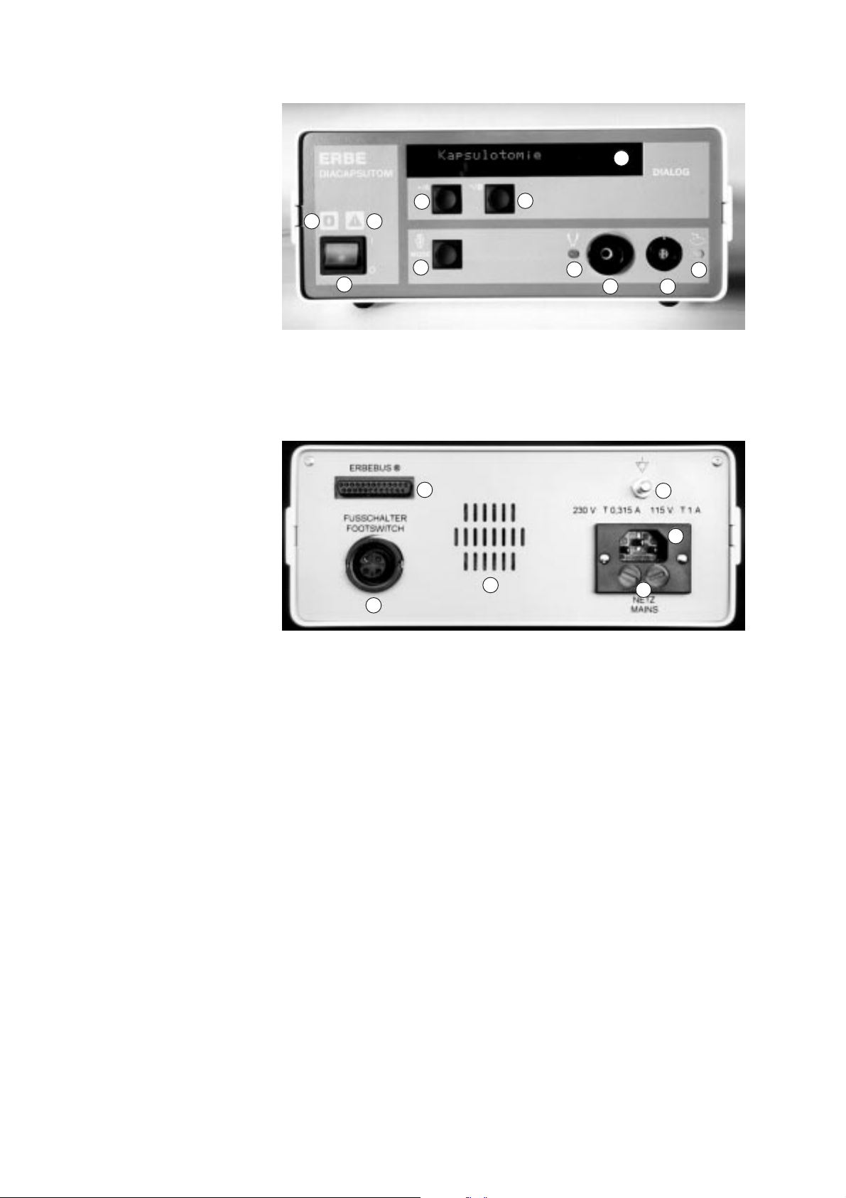
Fig. 1-1: DIACAPSUTOM front panel.
12
13
14
6
8
9
16
11
10
17
15
Fig. 1-2: DIACAPSUTOM back.
8
/50
CHAPTER 1: FIGURES ERBE DIACAPSUTOM
Page 9

DIACAPSUTOM operator controls
1. Power switch:ON/OFF switch for the power supply.
2. Symbol: Applied part Type BF
3. Symbol: “Attention, heed the instruction manual”
4. (See under 6)
5. Mode key. By using this ke y, th e var io us ope rating modes or setting
parameters can be selected.
6. +/A and -/B keys. Using these keys, program values and setup
parameters can be changed.
7. Display. Indicates the fo llowing information to the user:
– Setting val ues
– Error messages
– Using the softkeys +/A and - /B, the setup v alues c an be ch ange d.
8. Yellow LED (Bipolar). Lights up if the D
IATHERMY 2 is preselected.
D
9. Bipolar socket. Connecting socket for bipolar forceps and bipolar
electrodes .
10. Capsulotomy socket. Connecting socket for capsulotomy electrode.
11. Yellow LED (capsulotomy). Lights up when the C
operating mode is preselected.
12. ERBEBUS. This is a further developed interface system, which has
a simple conn ecting cabl e. In this wa y it is possi ble to opera te the
DIACAPSUTOM via the footswitch on the ERBE ASPIMAT E.
13. Footswitch socket. Connection for single or dual-pedal foot-
switches.
14. Speaker. During activation, a corresponding activation sound is
emitted according to the operating mode.
15. Power connection socket
16. Power fuses. The unit has 2-phase fuse protection.When replacing,
make certain to check the fuse ratings.
17. Terminal for potential equalization
IATHERMY 1 or
APSULOTOMY
Stand: 10 / 2000
Art.-Nr.: 80172-081
CHAPTER 1: FIGURES ERBE DIACAPSUTOM 9
/50
Page 10
Figures single-pedal footswitch and accessories
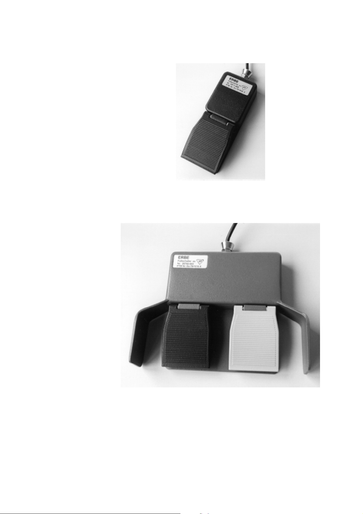
Fig. 1-3: Single-pedal footswitch (explosion-proof).
10
/50
Fig. 1-4: Dual-pedal footswitch (explosion-proof).
CHAPTER 1: FIGURES ERBE DIACAPSUTOM
Page 11
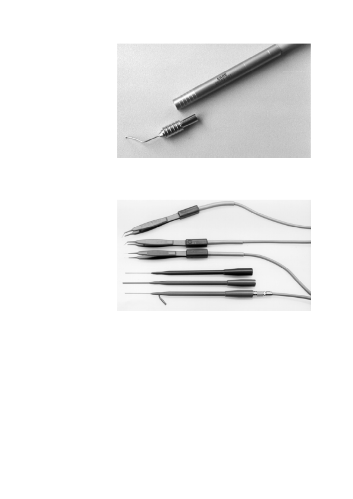
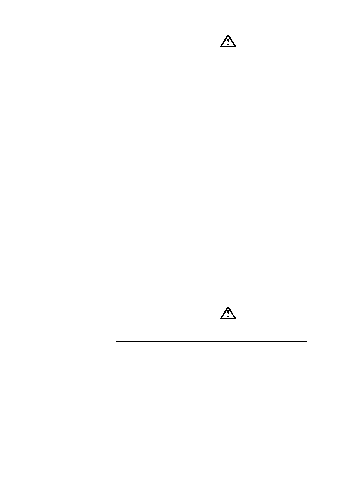
Fig. 1-5: Capsulotomy electrode with handle.
Fig. 1-6: Bipolar forceps and coagulation probes.
Footswitch
The unit may be activated via the explosi on-pr oof, single -pe dal foo tswitch
(Art. nos 20711-008 and 20711-009) or the explosion-proof dual-pedal
footswitch (Art. nos. 20743- 003 an d 20743-004). If activated via t he dualpedal footswitch, the operating mode may be preselected using the black
pedal and activated with the gray pedal.
Stand: 10 / 2000
Art.-Nr.: 80172-081
CHAPTER 1: FIGURES ERBE DIACAPSUTOM 11
/50
Page 12
CAUTION!
If the program is chan ged usi ng the bl ack ped al, thi s must b e confi rmed by
pressing the black pedal again (protection against unintentional operating
mode change).
Single-pedal footswitch, explosion-proof
(Art. no. 20711-008)
Single-pedal footswitch, non-explosion-proof, not shown.
(Art. no. 20711-009)
Dual-pedal footswitch, explosion-proof
(Art. no. 20743-003)
Dual-pedal footswitch, non-explosion-proof, not shown
(Art. no. 20743-004)
Accessories
• Handle with cable for capsulotomy electrode (Art. no. 20743-001)
• Capsulotomy electrode (Art. no. 20743-002)
• Bipolar forceps for closure of conjunctiva (pointed) compl. with
cable (Art. no. 20739-017)
• Bipolar forceps (angled, blunt) compl. with cable (Art. no. 20739-
061)
• Bipolar forceps (straight, blunt) compl. with cable (Art. no. 20739-
062)
• Endodiathermy probe with suction (Art. no. 20738-054)
• Endodiathermy probe without suction (Art. no. 20738-060)
• Bipolar coagulation probe (Art. no. 20738-064)
• HF bipolar cable for Art. nos. 20738-054/-060/-064 and 20738-028
12
/50
CAUTION!
Only the accessories listed here may be operated on the ERBE DIACAPSUTOM.
CHAPTER 1: FIGURES ERBE DIACAPSUTOM
Page 13

2 Intended use
Intended use
The ERBE DIACAPSUTOM is a high-frequency bipolar unit for diathermy and capsulotomy. It has the operating modes:
Operating modes •D
The unit may be operated as a single unit or together with ERBE phako
equipment.
IATHERMY 1 and 2 1. DIATHERMY 1 and 2: Two programs for bipolar application (bipolar
D
APSULOTOMY 2. CAPSULOTOMY: HF generator for performing HF capsulotomy with
C
Stand: 10 / 2000
Art.-Nr.: 80172-081
This may be activated via the pedal or multifunction footswitch
(ASPIMAT E).
IATHERMY 1,
IATHERMY 2,
•D
APSULOTOMY.
•C
forceps, bipolar pin and endodiathermy. Different intensities may
be preprogramed for various intstruments or different applications
such as "Wet-Field" coagulation and conjunctival closure. This can
be activated via the pedal or multifunction footswitch
(ASPIMAT E) .
special electrode. The following characteristics are of particular
interest in HF capsulotomy:
– automatic cutting control,
– automatic adaptation of HF current during various cutting
phases,
– minimal vapor bubble formation,
– very solid capsulotomy edge,
– clear view during cutting,
– automatic cutting control,
– very little sticking of the electrodes.
CHAPTER 2: INTENDED USE 13
/50
Page 14
Explanation of the safety instructions
Make certain to read all safety instructions marked with an exclamation
point before using the DIACAPSUTOM .
WARNING!
The WARNING safety instruction indicates a danger which can result in
injury.
CAUTION!
The CAUTION safety instruction indicates a danger which can result in
property damage.
A TTENTIO N!
The ATTENTION safety instruction indicates the danger which can cause
functional failure of the unit.
Who should read this
instruction manual?
Instructions for the user
The DIACAPSUTOM conforms to all relevant , generall y recogniz ed technical rules, as well as the valid regulations for occupational safety and accident prevention.
ATTENTION!
Only use accessories approved by ERBE Elektromedizin. If not, ERBE
Elektromedizin assumes no responsibility.
Everyone who prepares, adjusts, works with, dismantles, cleans or disinfects the unit and ins trument set s hould r ead the DIACAPSUTOM instr uction manual and the i nstruct ions for use fo r the acc essories . Pleas e pay particular attention to the safety instructions in every chapter.
WARNING!
The DIACAPSUTOM must only be used b y pe rso ns wh o, under consideration of this instruction manual, have been trained in the proper handling
of the DIACAPSUTOM or the unit combination (DIACAPSUTOM,
accessories).
14
/50
Training Training may only be conducted by persons whose knowledge and practi-
cal experience qualify them to do so.
ERBE Elektromedizin GmbH assumes no liability for damage due to improper application.
CHAPTER 2: INTENDED USE
Page 15

Questions, ERBE
Customer Hotline
If anything is unclear or i f you have questions, plea se contact an ERBE employee or your local ERBE business office, or use the ERBE Customer
Hotline. We would be pleased to assist you and appreciate your suggest ions
regarding this instruction manual.
Stand: 10 / 2000
Art.-Nr.: 80172-081
CHAPTER 2: INTENDED USE 15
/50
Page 16

16
/50
CHAPTER 2: INTENDED USE
Page 17

3 Maintenance and
care of the unit
and accessories
Maintenance
Maintenance of the unit and the reusable accessories includes preventive
and corrective mea sures for servi ci ng. Thus spec ifie d, r egula rly p erfor med
safety inspections (see Chapter 11) represent preventive measures, while
changes and repairs can be summarized under the concept of corrective
maintenance. Through regu la r mai nte nance of the unit, including t he r eusable accessories, the required status specified in the technical data should
be maintained, and the functionality and safety should be guaranteed at
least until the next maintenance deadline.
Changes and repairs
Safety inspection
only by a service
technician authorized
by ERBE
Changes and repair s to th e uni t or acce sso ries must not i nhibit the s afety of
the patient, the us er and the s urr ounding s. This is consi dered t o be f ulf ille d
if the structu ral and f unctio nal char acter isti cs ha ve not b een ch ange d to the
detriment of safety. Chang es and repairs to t he unit must only be perf ormed
by the manufacturer or by persons expressly authorized to do this by him
in consideration of the speci al safety requirements for high -f re quency surgical equipment. If nonauthorized persons perform incorrect changes and
repairs to the unit or accessories, the manufacturer accepts no liability. In
addition, the guarantee becomes void in this case.
Care of the unit
Stand: 10 / 2000
Art.-Nr.: 80172-081
Effective protection of the unit from damage also includes, in addition to
correct operation and maintenance, safe setting up of the unit. Besides secure fixation of the unit to its base, this also includes its protection from
moisture, contamination and contact with flammable or explosive materi-
CHAPTER 3: MAINTENANCE AND CARE OF THE UNIT AND ACCESSORIES 17
/50
Page 18

als. To ensure good radiat ion of unit heat resu lting during opera tion, air circulation must not be impeded.
Care of the accessories
To protect the accessor ies fr om prema ture wea r, the fol low ing inst ruct ions
must be observed:
• Do not clean and store forceps with insulated branches together
with other hard or pointy instruments, since the insulation may
become damaged in this way. Do not bend the forceps branches
apart since otherwise the coating may possibly chip off.
• Electrode handles. Do not wind the electrode handle cable around
the handle so that the cable is greatly stressed.
• Do not carry the f ootswit ch whil e hold ing by the cable. Do not wi nd
the cable tightly around the footswitch.
• Cable and plug. Do not roll up, kink or fold the cable. Pull the plug
by the plug shaft—never pull the cable forcefully from the sockets
on the high-frequency surgical unit.
• Electrodes are best cleaned with a fine brush—moving from the
connection end toward the front. Electrodes may also be cleaned in
an ultrasonic bath or in the washing machine up to +95 °C. Please
also observe the Notes on Use for the electrodes.
18
/50
CHAPTER 3: MAINTENANCE AND CARE OF THE UNIT AND ACCESSORIES
Page 19

4 Instructions for
the use of highfrequency
surgical
equipment
General information
1. The patient must not come into contact with metal parts that are
grounded or have a substantial capacity at ground (e.g. operating
table, brackets, etc.). Use of antistatic cloths is recommended for
this purpose.
2. Skin-to-skin contact (e.g. between arms and body of the patient)
should be prevented, e.g. by packing with dry gauze.
3. When using HF surgical and physiological monitoring equipment
on a patient at the same time, monitoring electrodes that have no
protective resistors or HF chokes should be attached as far as possible from the surgical electrodes. Needle electrodes are not recommended for monitoring.
4. The lines to the surgical electrodes should be arranged in such a
way that they contact neither the patient nor other lines.
5. The power output should be set at the lowest possible value neces-
sary for the intended purpose.
Stand: 10 / 2000
Art.-Nr.: 80172-081
6. Use of explosive anesthetics, dinitrogen monoxide N
gas) and oxygen should be avoided when operating in the area of
the thorax or head, unless these agents have been suctioned off or a
unit with anesthetic proof test is used. Flammable substances used
as cleaning agents, disinfectants or solvents for adhesive should
have evaporated before applying HF surgery. There is a danger that
O (laughing
2
CHAPTER 4: INSTRUCTIONS FOR THE USE OF HIGH-FREQUENCY SURGICAL EQUIPMENT
Page 20

flammable liquids will collect beneath the patient or in bodily
depressions such as the navel or bodily cavities such as the vagina.
Liquid that has collected in these locations should be wiped away
before using the unit. Warning should be given of the danger of
ignition of endogenous gases. Materials such as cotton and gauze
may be ignited by sparks occurring during intended use of the HF
surgical unit if they are saturated with oxygen.
7. For patients with cardiac pacemakers or pacemaker electrodes,
there is a risk that the pacemaker function may be disturbed or the
pacemaker could be damaged. Monitoring such patients by means
of measuring devices is r ecommen ded. In ca se of doubt, t he car diology department should be consulted.
8. The chance for disturbance of other electromedical equipment by
operation of the HF surgical unit
WARNING!
Unintentional activation of a high-frequency generator can lead to burns
on the patient if the active electrode hereby contacts the patient directly or
indirectly through electrically conductive objects or wet cloths.
Unintentional activation of a high-frequency generator can be caused, for
example, by:
• Unintentional pressing of a footswitch pedal,
• Short with in a cable to the footswitc h,
• Penetration of electrically conductive liquids into a footswitch.
Electrically conductive liquids are, for example, blood, amniotic
fluid, urine, physiological saline solutions, irrigation liquids, etc.,
• Errors within the high-frequency surgical unit.
To prevent burns to t he patient due t o unintentional activation of a high-frequency generator, the following rules for use should be observed:
1. Never lay active electrodes onto or next to a patient in such as way
that they may contact the patient directly or indirectly thro ugh electrically conductive objects or wet cloths.
2. The lines to the active electrodes should be arranged in such a way
that they contact neither the patient nor other lines.
3. Always set up the unit in such a way that acoustic signals may be
heard well.
Instructions for bipolar application
The bipolar surgical technique is especially suitable for thermal coagulation of blood vessels, i.e. for stopping hemorrhage. Here, the following
complications may occur:
20
Adhesive effect During the coagulation process, the coagulum may adhere more or less
firmly to the tip of the bipolar forceps, so that the coagulum is partially or
entirely separated from the surrounding tissue when removing the elec-
CHAPTER 4: INSTRUCTIONS FOR THE USE OF HIGH-FREQUENCY SURGICAL EQUIP-
/50
Page 21

trode and the blood vesse l is torn open by this. The adhesive effect pr imarily
results due to thermal conversion of collagen into glucose and the rapid
dessication of the more or less glucose-containing coagulum.
To prevent the ad hesive ef fect or at le ast k eep it as minimal as poss ible, the
HF current must be sw it che d of f a s soon as sufficient coagulum is present,
particularly because extending the time limit of the HF current beyond the
point at which coagulation has occurred has no advantage. In addition,
make certain that the bipolar forceps and electrodes are always clean, i.e.
that no tissue remnants from previ ous coag ulations adhere to the electrod e
surfaces.
The adhesive effect par ticularly resu lts when coagul ating relat ively dry tissue. In this case, sufficiently moistening the tissue to be coagulated with
sterile water o r phys iological saline s olution is recommended before coagulation.The blood flowing out of the ves sel to be coa gul ated is not suit able
for this purpose when stopping hemorrhage, bec ause it also coagulate s during the coagulation pr ocess. If th e forceps or elect rode adhere s to the coagulum in spite o f obse rving the a bove inst ructi ons, i t sho uld not b e remove d
forcibly from the tissue but instead left for a few seconds on the tissue after
switching off the HF current. Due to the capillary effect, tissue fluid flows
from the coagulum surroundings to th e ma rgi na l are as betwee n the coagulum and forceps tips and stops the adhesive effect. If necessary, a drop of
sterile water of physiological saline solution also helps.
Bursting of the
coagulum
Nonapplication of the
coagulation effect
If the high-frequency power is set too high during bipolar coagulation, the
intensity of the HF curr ent flowing betwee n the bipolar forceps tips through
the coagulum is so g reat that ext reme vapor pr essure result s due to a sudde n
severe increase in t emperature in t he tissue, whi ch tears apart the coagulum
explosively.This undesirable effect can be prevented by the correct setting
of HF power.
With every coagulation, the surface of the bipolar forceps is coated with
bodily fluid. After t he c oagulation process, while th e forceps are not bei ng
used, the tissue fluid dries off of the forceps surface and leaves behind an
electrically in sulating c oating. If such a force ps is r eused without removing
this coating first , not e nough HF curr ent ca n flow, esp ecial ly for d ry tissu e.
It is therefore recommended that the bipolar forceps be cleaned with a
moist sterile cloth between coagulations. After use, the bipolar forceps
should be treated in accordance with Chap. 9, “Cleaning, disinfection and
sterilization of accessories”.
The unit has not been tested for defibrilation resistance. It is therefore essential that no DIACAPSUTOM applied parts be in contact to the patient
during defibrilation.
Stand: 10 / 2000
Art.-Nr.: 80172-081
CHAPTER 4: INSTRUCTIONS FOR THE USE OF HIGH-FREQUENCY SURGICAL EQUIPMENT
Page 22

22
CHAPTER 4: INSTRUCTIONS FOR THE USE OF HIGH-FREQUENCY SURGICAL EQUIP-
/50
Page 23

5 Ambient
conditions
Operation
ATTENTION!
The DIACAPSUTOM should be operated at a room temperature between
+10 °C and +40 °C.
Storage, transport
ATTENTION!
The DIACAPSUTOM should be stored and transported at a room temperature between –40 °C and +70 °C.
Stand: 10 / 2000
Art.-Nr.: 80172-081
CHAPTER 5: AMBIENT CONDITIONS 23
/50
Page 24

24
/50
CHAPTER 5: AMBIENT CONDITIONS
Page 25

6 Installation of the
DIACAPSUT OM
Spatial requirements
High-frequency surg ical equipme nt must only be operated in ro oms intended for medical use which fulfill the appropriate requirements. The spatial
requirements, regarding electrical installation, concern for example the
grounded conductor system, the potenti al equaliz ation an d the gr ound fault
interrupt system.
Set-up possibilities in the operating room
In principle, the DIACAPSUTOM can be set up on tables , ceiling susp ended or wall-mounted arm consoles, as well as on special equipment carts.
Power connection
High-frequency surgical equipment must only be connected via the power
cable supplied by t he equipment manufact ur er or of equal quality, la bel le d
with the national t es t symbol , to properly instal led, grounded plugs. I n t hi s
case, no multiple power outlet s or exte nsi on co rds should be used if possible for reason of safe ty. If their use i s unavoi dable , the se too must be fit ted
with a proper grounded conductor. The power outlet must be secured with
a fuse of at least 10 A rated current.
Potential equalization
Equipment used during int racardia c intervent ions must b e connected t o the
potential equalization of the room. This is intend ed to prevent low-f requen-
Stand: 10 / 2000
Art.-Nr.: 80172-081
cy electrical curr ents, e.g. low- frequenc y leakag e currents from a defect ive
grounded conductor system, from endangering the patient. Although the
DIACAPSUTOM is not intended for intracardiac interventions, it has been
equipped with a potential equalization connection pin on the rear panel of
the unit to fulfill the safety requirement. In this way, the unit can be con-
CHAPTER 6: INSTALLATION OF THE DIACAPSUTOM 25
/50
Page 26

nected via a potential equalization line to a potential equalization connection in the room where it is set up.
Explosion protection
High-frequency surgical equipment intentionally generates electric sparks
between the active electrode and tissue. Electric sparks may also result
within the unit. For this reason, high-frequency surgical equipment must
not be used in potent ially explosi ve areas. Consider ed potential ly explosive
is the area up to 20 cm above the floor and the area around and bene at h the
operating table, if flammable or explosive cleaning agents, disinfectants,
anesthetics etc. are used. High-frequency surgical equipment is normally
installed outside the zone designated as potentially explosive.
WARNING!
Footswitches must be designed as explosion-proof if they are used in
potentially explosive areas.
Protection from moisture
The DIACAPSUTOM high-frequency surgical uni t is protected against th e
penetration of moisture in accorda nce with EN 60601-1. Never theless, t his
unit should not be set up i n the vicinity of t ubes or containers which contain
liquid. Liquids should not be placed above or even on the unit. Only those
single-pedal footswitches should be used which are watertight in accor-
dance with EN 60601-2-2, § 44.6 aa.
Cooling
The ERBE Diacapsutom must be set up in such a way that free air circulation around the housing i s ensu red. The refor e sett ing up in nar row corn ers,
shelves etc. is not permissible.
HF disturbances
High-frequency sur gical eq uipment inte ntionally generates high-freq uency
voltages and currents. Ther ef ore , car e must be tak en dur ing set-up and operation that the function of other electromedical equipment cannot be disturbed.
26
/50
i
Note: The ERBE DIACAPSUTOM produces far less HF disturbance than
conventional high-frequency surgical equipment, thanks to automatic regulation, which is par ticularl y advantag eous when u sed in co mbinati on with
video monitors.
CHAPTER 6: INSTALLATION OF THE DIACAPSUTOM
Page 27

Setting the dialogue language
Language When switching on, continue pressing the +/A key. Appearing then on the
display, for example, is
Now you may select one of t he languages Deutsch, Engl ish , Fr anç ai s, It aliano, Espanol, Polska, Portugues by repeated switching of the +/A key.
By pressing the B key, the sel ected languag e is accept ed. Now all te xt s appear in this language.
Programming the unit
In the DIATHERMY 1 and DIATHERMY 2 programs, intensities can be programmed:
1. Keep tapping the Mode key until D
play.
2. Using the +/A and -/B keys, the required intensity can now be set.
3. Change to D
4. Now the required intensity can also be set using the +/A and -/B
keys.
IATHERMY 2 using the Mode key.
IATHERMY 1 appears on the dis-
i
Important: The intensity values set remain stored until the next change.
In the C
ting control provides optimal power for every situation.
APSULOTOMY program, the intens it y ne ed no t be set, since the cut-
Stand: 10 / 2000
Art.-Nr.: 80172-081
CHAPTER 6: INSTALLATION OF THE DIACAPSUTOM 27
/50
Page 28

28
/50
CHAPTER 6: INSTALLATION OF THE DIACAPSUTOM
Page 29

7 Testing the
performance
To check the funct io nal readiness of t h e uni t , t he operator should carry out
a performance test before every use.
1. If the DIACAPSUT OM is prop erly c onnect ed to the AC p ower sup-
ply via the supply cable, the pilot lamp in the power switch should
be illuminated when the power switch is switched on.
2. Connect the bipolar forceps of bipolar electrode to the appropriate
socket.
3. Bring this into contact with a wet sponge.
4. Activate the unit at the maximum power setting with the footswitch.
During activation, an acoustic signal must be heard.
5. It is possible to verify with the help of a wet sponge whether high-
frequency power is available at the bipolar output. If properly functioning, water vapor results as soon as both tips of the bipolar forceps or bipolar electrode contact the sponge.
WARNING!
The DIACAPSUTOM may only be used when it functions properly in the
test.
Stand: 10 / 2000
Art.-Nr.: 80172-081
CHAPTER 7: TESTING THE PERFORMANCE 29
/50
Page 30

30
/50
CHAPTER 7: TESTING THE PERFORMANCE
Page 31

8 Working with the
DIACAPSUTOM
Stand: 10 / 2000
Art.-Nr.: 80172-081
CHAPTER 8: WORKING WITH THE DIACAPSUTOM 31
/50
Page 32

Fig. 8-1: Guide the electrode slowly and evenly over the capsule within the required diameter. Set the electrode down carefully and tilt it slightly in the direction of pull.
Diathermy 1
MODE
Diathermy 2
MODE
Capsulotomy
A: Setups
MODE
MODE
+/A
Volume 50 %
MODE
32
/50
Diath.1 max. 10 s
Diath.2 max. 10.0 s
MODE
Capsulot. max. 60 s
Fig. 8-2: Flowchart for changing the set values (see pag e 34).
CHAPTER 8: WORKING WITH THE DIACAPSUTOM
MODE
MODE
Page 33

Procedure
The DIACAPSUTOM can be activated via three possibilities:
• Via the single-pedal footswitch,
• V ia dua l-ped al foo tswi tch, i .e. during the op era tion, nothin g need b e
set on the unit. This means high operational convenience during
surgery,
• Via multifunction footswitch (ERBE phako equipment).
Putting into operation
Once the bipolar forceps or bipolar electrode has been connected as described in the Performanc e test chapt er and t ested wi th the unit, pr oceed a s
follows:
1. Switch the unit on at the gr een mast er swit ch (1) . The uni t per for ms
a self-check. When this has been successfully completed, a melody
is heard and the unit introduces itself on the display with its name
and software version.
2. Then the program that was last used appears. At the same time, the
LED for the associated connecting socket and the intensity setting
blinks on the display. By pressing one of the keys Mode A or the
black pedal (dual-pedal footswitch), this is acknowledged.
3. If work is to proceed at a different intensity, this can be changed
accordingly using the +/A and -/B keys.
4. To change to a different program, the Mode key or the black pedal
(dual-pedal footswitch) is pressed.
If the program is changed using the black pedal (dual-pedal footswitch),
this must be acknowledged by pressing again. To activate, the gray pedal
(dual-pedal footswitch) is pressed.
Operating modes
Working with the
single pedal
footswitch
Working with the
multifunction
footswitch ERBE
phako equipment
Stand: 10 / 2000
Art.-Nr.: 80172-081
Working with the
IATHERMIE 1 und 2
D
programs
1. Single-pedal footswitch: If working with the single-pedal foot-
switch, the operating mode can be repeatedly switched using the
Mode key.
2. Multifunction footswitch ERBE phako equipment: The unit can be
connected to ERBE phako equipment vi a the connecting cable (Art .
no. 20720-019). It is activated using the black key. With the yellow
key, the operating modes can be selected and acknowledged. CAU-
TION: If the ASPIMAT E is in a vitrectomy program, the yellow
key is used to control the vitrectomy part.
3. D
IATHERMY 1 and 2: With these programs it is possible to store
intensities for var iou s ins tr ument s (e .g. bipolar forceps, bipolar pin s
or endodiathermy) or surgical steps. Using the Mode key or the
black pedal (dual-pedal switch) the required program is selected
and acknowledged. Using the +/A and -/B keys, the intensity is
CHAPTER 8: WORKING WITH THE DIACAPSUTOM 33
/50
Page 34

adjusted. The values remain stored in memory until the next
change. It is activated using the gray pedal (dual-pedal footswitch).
Working with the
C
APSULOTOMY
program
Volume Via keys +/A and -/B, the volume of the speaker (14) and the max. activa-
4. C
APSULOTOMY: No power need be adjusted here, since the cutting
control guarantees a uniform incision here. The program is selected
or acknowledged using the Mode key or the black pedal (dualpedal footswitch). For HF capsulotomy, the anterior chamber is
filled with a viscoelastic solution. It is activated using the gray
pedal (dual-pedal footswitch).
Important: The electrode is moved sl owly and evenly on the capsul e in the
required diameter. In this way a clean and smooth incision is achieved!
Changing the adjustment values (see also
Page 32)
tion times can be changed.
To change the volume, proceed as follows:
1. Tap the Mode key so many times until
display. By pressing the +/A key again,
display.
2. Now set the required volume using the +/A and -/B keys.
3. Keep tapping the Mode key to return to the application program.
A: Setups appears on the
Volume xx% appears on the
Activation time limit An activation time limit can be set for every program.
1. Keep tapping the Mod e key until
By presing the +/A key again,
2. Keep tapping the Mode key so many times until the operating
mode, the activation time limit of which is to be changed, appears
on the display.
3. Now you can set the required activation time limit (from
0.1 seconds) using the +/A and -/B keys.
4. By pressing the Mode key again, you reach the D
gram to set the time there.
5. Pressing again allows you to set the time for the capsulotomy.
6. By pressing the Mode key once again, you return to the application
program.
7. To return to the necessary application program, the Mode key must
be tapped an appropriate number of times.
A: Setups appears on the disp la y.
Volume appears on the display.
IATHERMY 2 pro-
34
/50
CHAPTER 8: WORKING WITH THE DIACAPSUTOM
Page 35

9 Cleaning,
disinfection,
sterilization
Unit
• Clean and disinfec t t he unit with a spray or wipe- down di si nf ection.
Observe the instructions from the disinfectant manufacturer.
• Sterilization of the unit is not possible.
WARNING!
If cleaning or disinfection of the unit with flammable or explosive agents
is unavoidable, they must have completely evaporated from the unit
before switching on.
Bipolar active electrodes and forceps
• Disinfect and sterilize new probe tips before initial application.
• Please observe the information from the disinfectant manufacturer.
• Never use sharp objects for cleaning.
• Do not clean in the washing machine.
• Autoclavable up to 134 °C in saturated steam.
• Do not prepare using ETO or formaldehyde.
Do not scratch off tissue remna nts and drie d-on bodily fluids from the electrodes using hard, sharp objects such as scalpels, scissors or knives. This
Stand: 10 / 2000
Art.-Nr.: 80172-081
CHAPTER 9: CLEANING, DISINFECTION, STERILIZATION 35
can damage both the insulation and the contact surfaces of the electrodes.
Dried-on tissue re mnants or bod ily fl uids c an gene rall y be l oosene d slig htly in warm water and then wiped off with a soft cleaning rag. Tissue burnt
onto the electro des can be careful ly rubbe d off using fi ne metal wool if t his
is the only option.
/50
Page 36

CAUTION!
Aldehydic preparations are better suited for disinfection of electrode handles than phenolic agents, since they are less aggressive toward the plastic
used.
CAUTION!
T o prevent prema ture wear , make abs olutely cer tain to observ e the instructions from the disinfectant manufacturer regarding soaking time and the
concentration of agents used.
CAUTION!
The disinfectants must be rinsed off well.
Footswitch
Explosion-proof footswitches can be surface disinfected with all common
disinfectants.
Non-explosion-proof footswitches must only be cleaned or disinfected
with nonflammable and nonexplosive agents.
36
/50
CHAPTER 9: CLEANING, DISINFECTION, STERILIZATION
Page 37

10 Visual and
acoustic error
messages
The unit’s microprocessor control systems constantly measure and com pare all necessary paramet ers during a ctiva tion. In this way, t he unit f unctions and the ge ner ator function are always monitored. I f an error is recognized, an acoustic warning s ignal sounds , the HF genera tor is swit ched off,
and an error message appears on the display. Possible error sources are:
• Unit defect
• Damaged accessories
•User error
The error message consists of a plain text error messa ge and an error number. Any error number appearing should be noted for possible error diagnosis.
Remedy If the cause of the erro r is recogn ized and coul d be rect ified ind ependentl y,
the error message may then be deleted by pressing key A (4) or the footswitch. The unit is then ready for renewed activation.
Stand: 10 / 2000
Art.-Nr.: 80172-081
CHAPTER 10: VISUAL AND ACOUSTIC ERROR MESSAGES 37
/50
Page 38

38
/50
CHAPTER 10: VISUAL AND ACOUSTIC ERROR MESSAGES
Page 39

11 Safety checks
To prevent a reduction in unit safety due to age, wear etc., § 6 of the regulation prescribe s regula r safet y checks in rega rd to the settin g up, ope ration
and application of active medical products (Betreib VaMP). The operator
must perform specifi c sa fe ty checks of a prescribed scope within the specified time for this unit. The safety checks must only be entrusted to those
persons who are able to perform the se checks properly due to their training,
knowledge and experienc e achieved through practical app lication, and who
are able to perform this inspection without supervision.
The following safety checks have been established for the DIACAPSUTOM:
• Checking the labels and instruction manual. All labels (writing on
the front and rear panel) must be easily legible. The instruction
manual must be available.
• Visual inspection of the unit and accessories for damage. Particularly the sockets, plugs and cables for the unit and the accessories
must be checked for perfect condition.
• Checking the electrical safety as defined in DIN VDE 0751, Part 1.
This includes a grounded conductor test and a leakage current test
in accordance with VDE 0751. Alternately, t he l ea kage cur re nt s can
also be measured and evaluated in accordance with EN 60 601-1.
• Performance test of all the unit's visual signals.
• Performance test of all the unit's acoustic signals.
• Measurement of he high-frequency outputs in the Capsulotomy and
Diathermy operating modes. Refer to the technical data (Page 43),
the line “HF power outp ut” as a function of the load resistor.
• The DIACAPSUTOM high-frequency surgical unit must receive a
safety inspection at least once annually. If defects are determined
during the safety inspections, which could endanger patients,
employees or third parties, the unit must no longer be used until
Stand: 10 / 2000
Art.-Nr.: 80172-081
these defects hav e been re ctif ie d by a prof essi onal te chnica l s ervic e.
CHAPTER 11: SAFETY CHECKS 39
/50
Page 40

40
/50
CHAPTER 11: SAFETY CHECKS
Page 41

12 Guarantee
conditions
Transport damage
The unit and accessories must be inspected immediately upon delivery for
defects and transport damage. Claims for damage in this regard are only
valid if the seller or carrier is notified immediately. A damage report must
be prepared.
Unit guarantee
The term of the guarantee for the DIACAPSUTOM high-frequency surgical unit is 1 year, calculated from the day of delivery.
A guarantee claim may only be made if the correctly filled out guarantee
certificate is presented.
The scope of the guarantee encompasses repair of the high-frequency surgical unit free of charge, on the condition that damage was caused by material or manufacturing er ror. All othe r claims, in parti cular claims of compensation, are excluded.
Repairs must only be made by us, our representatives or by author ized dealers. The guarantee claim becomes void if unauthorized changes or repairs
were made.
The guarantee is neith er extended nor rene wed through gua rantee se rvice s.
Stand: 10 / 2000
Art.-Nr.: 80172-081
CHAPTER 12: GUARANTEE CONDITIONS 41
/50
Page 42

42
/50
CHAPTER 12: GUARANTEE CONDITIONS
Page 43

13 Technical data
Stand: 10 / 2000
Art.-Nr.: 80172-081
CHAPTER 13: TECHNICAL DATA 43
/50
Page 44

Unit
Power connection
• 10743-000
• 10743-001
• 10743-002
230 V ± 10 %
115 V ± 10 %
100 V ± 10 %
Rated power frequency
Power fuse
Protection class acc. to EN 60601-1
Equipment type acc. to EN 60601-1
Classification acc. to EG-Directive 93/42/EWG
Power input
Low-frequency leakage currents:
• Ground leakage current
• House leakage current (Capsulotomy)
• Leakage current bipolar output
HF power output:
• Cutting (Capsulotomy)
• Bipolar coagulation (Diathermy)
HF peak output voltage:
• Cutting (Capsulotomy)
• Coagulation (Diathermy)
50 / 60 Hz
(230 V): T 315 mA
(115 V): T 1 A
(100 V): T 1 A
I
BF
Class IIb
60 W max.
0.5 mA max.
0.1 mA max.
0.1 mA max.
5 W at 350 Ω
22 W at 125 Ω
210 V max.
190 V max.
Rated freq uency
350 kHz
Power settin g
• Cutting (Capsulotomy)
• Coagulation (Diathermy)
automatic
infinite from
1–100 %
Activation of HF power
Dimensions w×h×d
Footswitch or
ERBE BUS
®
230×100×330 mm
Weight approx. 5.1 kg
Operation
Temperature +10°C … +40°C
Relative air humidity 30 % … 75 %
3
44
/50
CHAPTER 13: TECHNICAL DATA
Page 45

Storage, transport
Temperature
Relative air humidity
–40°C … +70°C
30 % … 95 %
Stand: 10 / 2000
Art.-Nr.: 80172-081
CHAPTER 13: TECHNICAL DATA 45
/50
Page 46

Power with diathermy
46
/50
Fig. 13-1: Power with diathermy.
CHAPTER 13: TECHNICAL DATA
Page 47

P in watts
Power with diathermy at 125 ohms
Setting in %
Fig. 13-2: Power with diathermy at 125 Ω.
Stand: 10 / 2000
Art.-Nr.: 80172-081
CHAPTER 13: TECHNICAL DATA 47
/50
Page 48

Software current limitation
Power with capsulotomy
48
/50
Fig. 13-3: Power with capsulotomy.
CHAPTER 13: TECHNICAL DATA
Page 49

50
/50
 Loading...