

Page 1
User’s Manual
400665709
Page 2
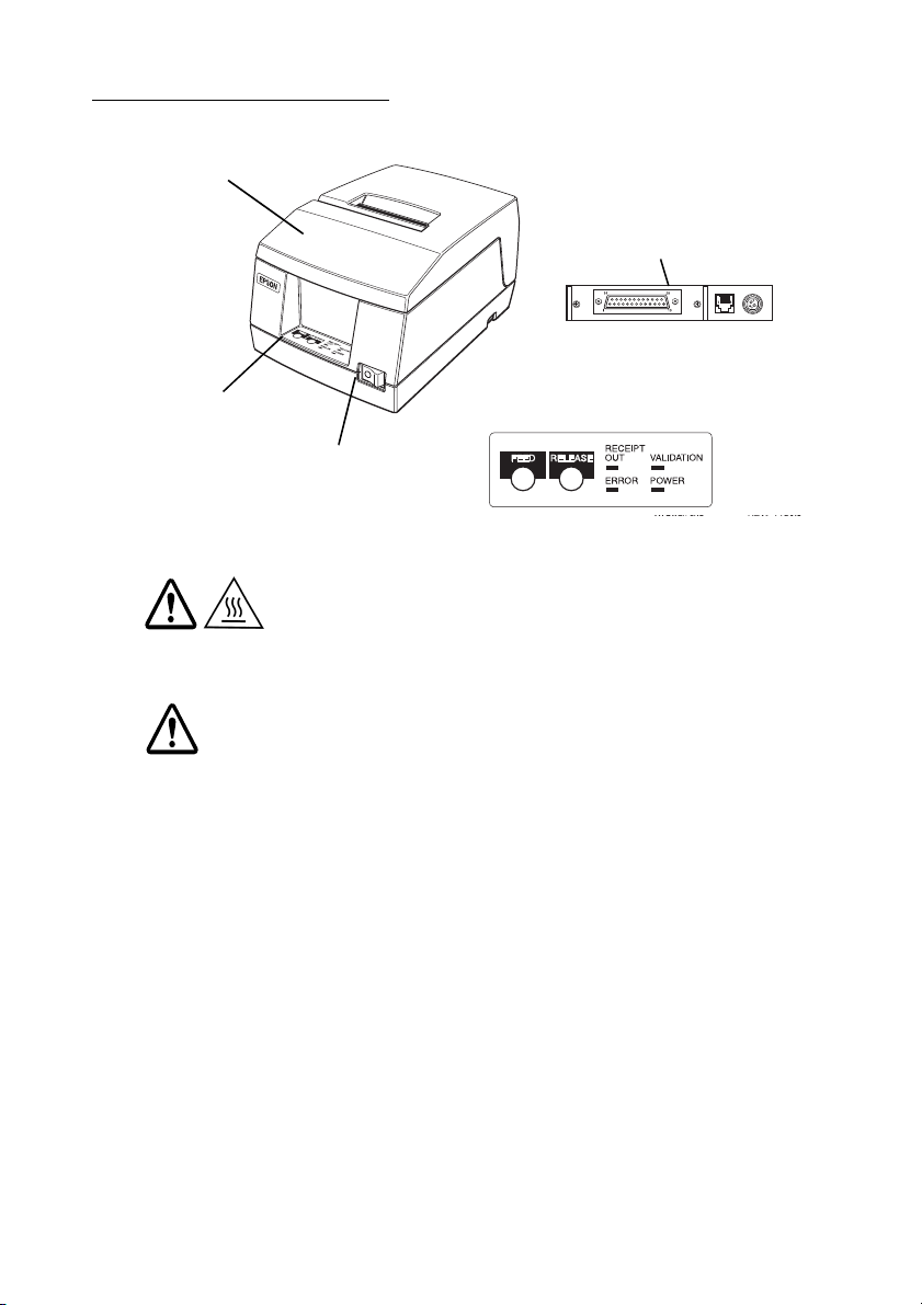
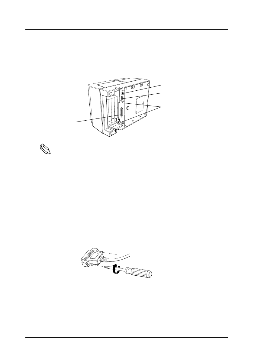
Printer Parts and Labels
Control panel
Printer cover
On/Off switch
Control panel
Serial interface connector
Labels
CAUTION:
Print head cover and print head are hot.
CAUTION:
Caution label for drawer kick-out connector.
Page 3

All rights reserved. No part of this publication may be reproduced, stored in a retrieval system, or
transmitted in any form or by any means, electronic, mechanical, photocopying, recording, or otherwise,
without the prior written permission of Seiko Epson Corporation. The contents of this manual are
subject to change without notice. While every precaution has been taken in the preparation of this
manual, Seiko Epson Corporation assumes no responsibility for errors or omissions. Neither is any
liability assumed for damages resulting from the use of the information contained herein.
Neither Seiko Epson Corporation nor its affiliates shall be liable to the purchaser of this product or third
parties for damages, losses, costs, or expenses incurred by purchaser or third parties as a result of:
accident, misuse, or abuse of this product or unauthorized modifications, repairs, or alterations to this
product, or (excluding the U.S.) failure to strictly comply with Seiko Epson Corporation’s operating and
maintenance instructions.
Seiko Epson Corporation shall not be liable for any damages or problems arising from the use of any
options or any consumable products other than those designated as Original Epson Products or Epson
Approved Products by Seiko Epson Corporation.
EPSON is a registered trademark of Seiko Epson Corporation. Exceed Your Vision is a registered
trademark or trademark of Seiko Epson Corporation. All other trademarks are the property of their
respective owners and used for identification purpose only. Product information is subject to change
without due notice.
© Seiko Epson Corporation 1996-2016. All rights reserved.
i
Page 4
About This Manual
Setting Up and Using
❏ Chapter 1 contains information on setting up the printer.
❏ Chapter 2 contains information on using the printer.
❏ Chapter 3 contains troubleshooting information.
Reference
Chapter 4 contains specifications and character code tables.
Warnings, Cautions, and Notes
WARNING:
Warnings must be followed carefully to avoid serious bodily injury.
CAUTION:
Cautions must be observed to avoid minor injury to yourself or damage to
your equipment.
Note:
Notes have important information and useful tips on the operation of your
printer.
Downloading Drivers, Utilities, and Manuals
The latest versions of drivers, utilities, and manuals can be downloaded
from the following URL:
http://www.epson.com/support/
ii
Page 5

Introduction
Features
The TM-U325D is a high-quality POS printer that can print a multiple-line validation and on
receipt paper (roll paper). The printer has the following features:
❏ Excellent reliability (long life) and good operability (drop-in paper loading).
❏ Multiple-line validation printing (possible to print a maximum of 9 lines).
❏ Compact and light in weight.
❏ High-speed printing through logic-seeking control.
❏ Excellent reliability and long life due to adoption of stepping motor, both for moving the
carriage and for paper feeding.
❏ Flexible line space setting permits printing in accordance with any user-defined format.
❏ Conforms with ESC/POS; excellent universality of control.
❏ Built-in drawer kick-out interface provides capability to drive two drawers.
❏ Selectable character fonts (7 × 9 and 9 × 9).
❏ Semi-automatic paper loading capability.
❏ AC adapter provides compact power supply.
❏ Automatic status back (ASB) function that automatically transmits changes in printer
status.
Accessories
❏ AC adapter
❏ Epson ribbon cassette, ERC-38
Options
Printer fastening tape (Model No. DF-10)
Restriction of Use
When this product is used for applications requiring high reliability/safety, such as
transportation devices related to aviation, rail, marine, automotive, etc.; disaster prevention
devices; various safety devices, etc.; or functional/precision devices, etc.; you should use this
product only after giving consideration to including fail-safes and redundancies into your
design to maintain safety and total system reliability. Because this product was not intended
for use in applications requiring extremely high reliability/safety, such as aerospace
equipment, main communication equipment, nuclear power control equipment, or medical
equipment related to direct medical care, etc., please make your own judgment on this
product’s suitability after a full evaluation.
iii
Page 6

Chapter 1
Setting Up the Printer
Selecting a Location
Place the printer on a surface that is as horizontal as possible. Make sure
that the printer does not tilt more than 15 degrees.
The printer should be installed so that it does not move or vibrate during
paper cutting or the drawer kick-out operation.
Fastening tape is available as an option.
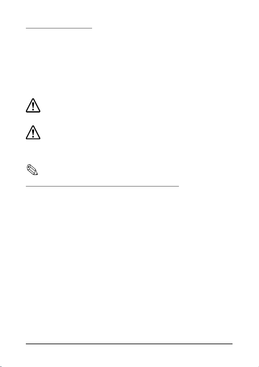
Adjusting the Roll Paper Near-End Sensor
Notes:
Use rolls of paper with an inner core diameter of 10.5 to 12.5 mm so
that the sensor detects the remaining paper correctly.
When the last portion of a roll paper bears red markings, the marking
is sometimes an adhesive that pulls the entire roll paper up. In this
case, the sensor may not detect the remaining paper correctly.
If the roll paper easily becomes loose because of the quality of the
paper or other factors, incorrect detection of the paper end may result.
1. Make sure that the power supply is disconnected from the printer.
1–1 Setting Up the Printer
Page 7
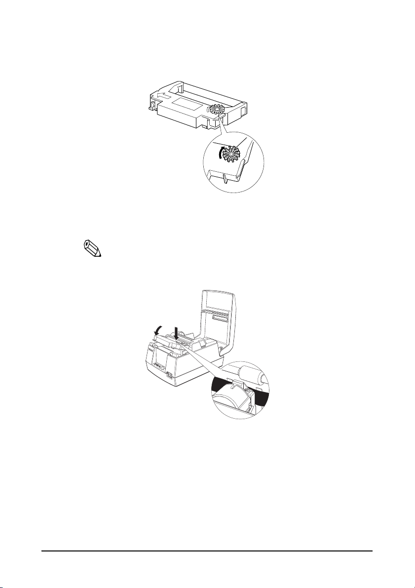
2. Two spacers are included. See the illustration below and decide whether
Distance A
Spacers
Roll paper
near-end sensor
or not you want to use them. Use them if you want the near-end sensor to
be triggered when distance A is 3 to 4 mm; otherwise it will be triggered
when distance A is approximately 6 mm.
3. Secure the roll paper near-end sensor (and spacers) with two screws.
When you insert the spacers, be sure you set the spacers in the direction
shown in the illustration.
4. Check to be sure that the detecting lever moves freely.
Setting Up the Printer 1–2
Page 8
Connecting the Cables and Grounding the Printer
Power supply
Drawer kick-out
Interface
Grounding screws
You can connect up to three cables and a grounding wire to the printer.
They all connect to the connector panel on the bottom of the printer,
which is shown below:
Notes:
There is a caution label beside the drawer kick-out connector.
Depending on the interface installed, the interface connector on your
printer may look different from the one illustrated.
Before connecting any of the cables, make sure that both the printer and
the computer are turned off.
Connecting the Computer
1. Plug the cable into the connector on the printer and tighten the screws
on both sides of the cable connector, as shown.
2. Connect the other end of the cable to the connector on your computer.
1–3 Setting Up the Printer
Page 9
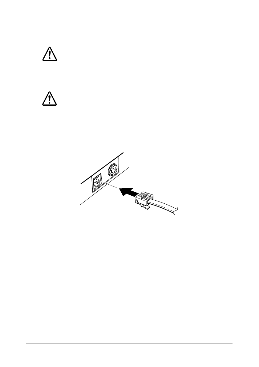
Connecting the Drawer
WARNING:
Use a drawer that matches the printer specification. Using an improper
drawer may damage the drawer as well as the printer.
CAUTION:
Do not connect a telephone line to the drawer kick-out connector;
otherwise the printer and the telephone line may be damaged.
Plug the drawer cable into the drawer kick-out connector on the bottom of
the printer next to the power supply connector.
Grounding the Printer
You need a ground wire to ground your printer. Make sure that the wire
meets the specifications below.
Thickness of wire: AWG 18 or equivalent
Diameter of terminal to be attached: 3.2
1. Make sure that the printer is turned off.
Setting Up the Printer 1–4
Page 10
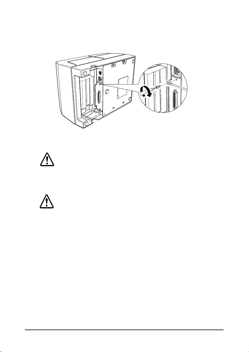
2. Connect the ground wire to the printer using the FG screw on the bottom
of the printer, as shown.
Connecting the Power Supply
WARNING:
Be sure to use the specified AC adapter. Connection to an improper power
source may cause fire.
CAUTION:
When connecting or disconnecting the power supply from the printer,
make sure that the power supply is not plugged into an electrical outlet;
otherwise you may damage the power supply or the printer.
If the power supply’s rated voltage and your outlet’s voltage do not match,
contact your dealer for assistance. Do not plug in the AC cable. Otherwise
you may damage the power supply or the printer.
1. Make sure that the printer’s power switch is turned off, and the power
supply’s AC cable is unplugged from the electrical outlet.
1–5 Setting Up the Printer
Page 11
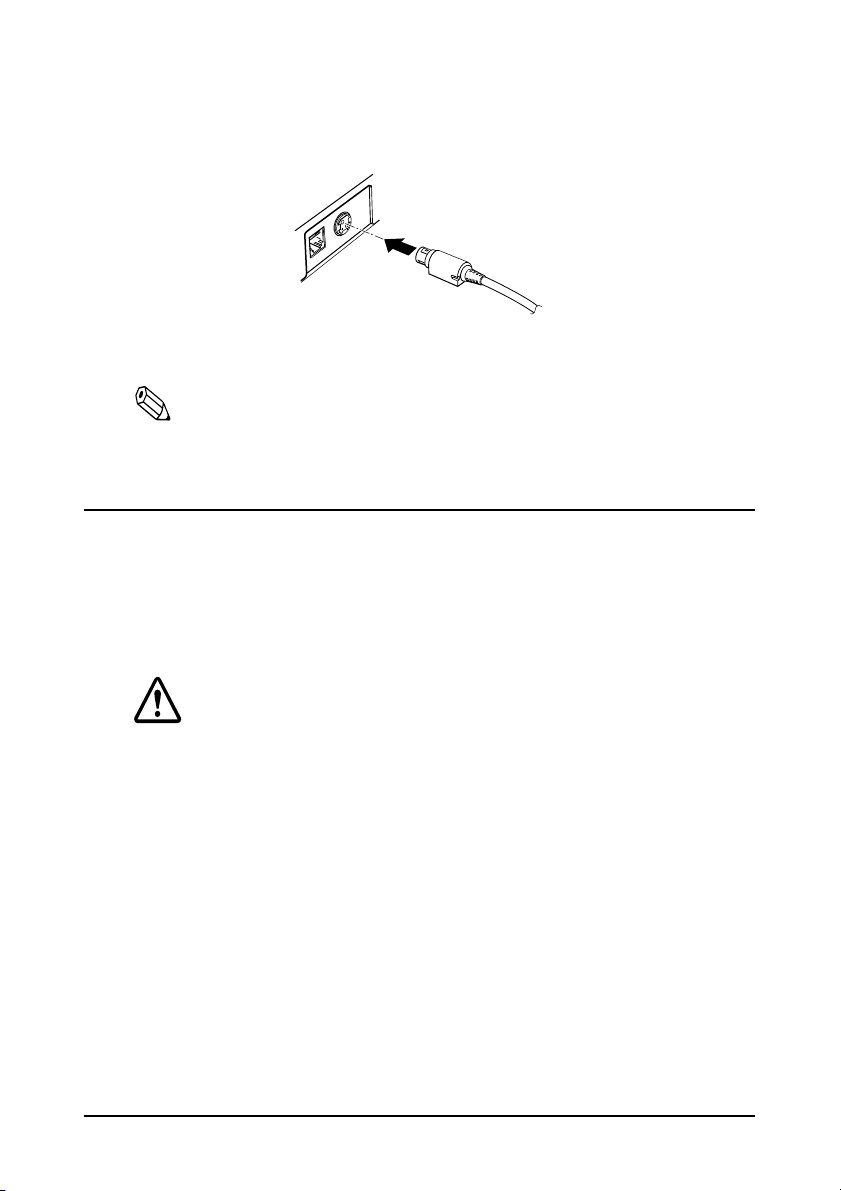
2. Plug in the power supply’s cord as shown below. Notice that the flat side
of the connector faces down.
3. Plug the power supply’s AC cable into an outlet.
Note:
If you ever need to remove the cable, unplug the power supply’s AC
cable from the outlet and then grasp the connector firmly at the arrow
mark and pull it straight out.
Installing the Ribbon Cassette
Use the Epson ERC-38 ribbon cassette for your printer.
Note the label inside the printer cover that can assist you in installing the
ribbon.
CAUTION:
Never turn the ribbon cassette’s feed knob in the opposite direction of the
arrow marked on the cassette; otherwise the ribbon cassette may be
damaged.
1. Be sure the printer is not receiving data when you replace a ribbon
cassette; otherwise data may be lost.
2. Open the printer cover.
Setting Up the Printer 1–6
Page 12
3. Turn the ribbon cassette’s knob in the direction of the arrow, to take up
any slack in the ribbon.
4. Insert the ribbon in the position shown in the illustration below and push
the ribbon cassette until it clicks.
Note:
Make sure that the ribbon is installed between the print head and
the platen without wrinkles or creases.
1–7 Setting Up the Printer
Page 13
5. Turn the ribbon cassette’s knob 5 or 6 times in the direction of the arrow
again, to take up any slack in the ribbon.
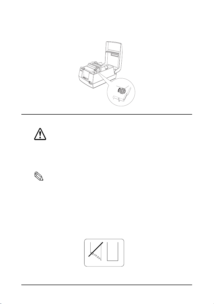
Installing Roll Paper
CAUTION:
Take care not to injure your fingers on the manual cutter
• When you remove printed paper
• When you perform other operations such as loading/replacing roll
paper
Notes:
Be sure to use roll paper that meets the specifications.
Do not use rolls of paper that have the paper glued to the core because
the printer cannot detect the paper end correctly. However, if you will
stop the printing using the roll paper near-end sensor, you can use
glued roll paper.
1. Using scissors, cut the leading edge of the roll paper as shown below.
Setting Up the Printer 1–8
Page 14
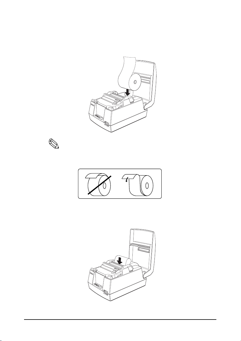
2. Turn on the printer and open the printer cover.
3. Insert the roll paper.
Note:
Be sure to note the correct direction that the paper comes off the
roll as shown below.
4. Hold both edges of the paper and insert it straight into the paper slot. The
printer feeds the paper automatically.
1–9 Setting Up the Printer
Page 15
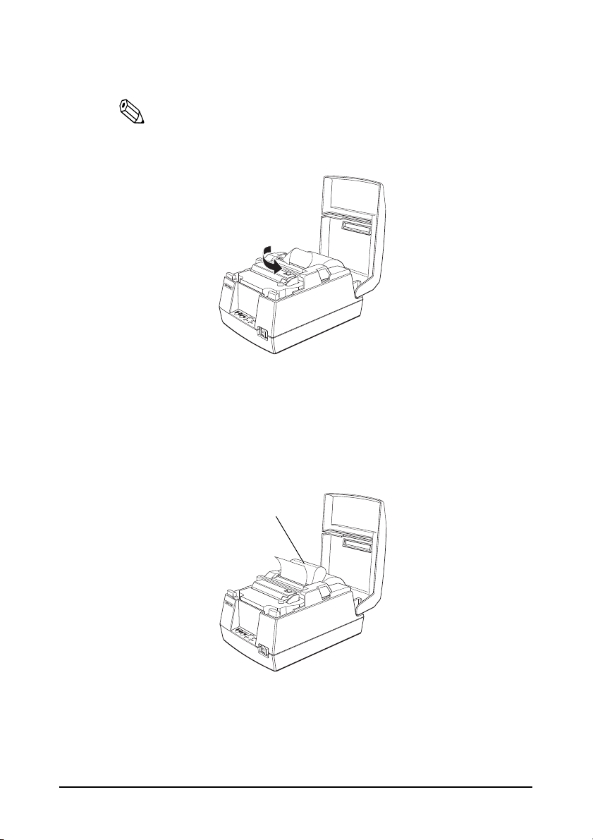
5. Tear off the paper; then close the cover.
Cut here
Note:
Before closing the cover, make sure that the roll paper has no
slack.
To remove the roll of paper, follow the steps below.
1. Open the printer cover.
2. Pull up the paper and cut the paper at the dotted line shown in the
illustration below.
3. Remove the roll paper from the printer.
4. Press the FEED button to remove the remaining paper.
Setting Up the Printer 1–10
Page 16

Running a Self-test
Any time that you want to check the performance of your printer, you can
run a Self-test described below. This shows whether your printer is
working correctly. It is independent of any other equipment or software.
Note:
Be sure to install the ribbon cassette and the roll paper before you
run the Self-test.
1. To perform a Self-test, hold down the FEED button while you turn on
the printer with the power switch.
2. The printer prints the current printer settings and then the RECEIPT OUT
light flashes to indicate that the printer is in the test printing standby state.
3. Press the FEED button to start the second part of the test, in which the
printer prints a pattern using the built-in character set.
4. After the printer completes a certain number of lines, it prints the
following:
*** completed ***
Then it enters the normal mode.
Note:
If you want to pause the Self-test manually, press the FEED
button. Press the FEED button again to continue the Self-test.
Setting the DIP Switches
CAUTION:
Turn off the printer while removing the DIP switch cover to prevent an
electrical short, which can damage the printer.
If you have special requirements, you can change the DIP switch settings.
1. Make sure that the printer is off.
1–11 Setting Up the Printer
Page 17

2. Turn the printer over and remove the DIP switch access cover, as shown
below.
3. There are two sets of switches. Notice that ON is marked on each set of
switches. Use tweezers or another narrow tool to move the switches.
4. Use the following tables to set the DIP switches. Numbers starting with 1
are in the first set, and numbers starting with 2 are in the second.
DIP Switch Set 1
Switch Function ON OFF
1-1 Data reception error Ignored Prints”?”
1-2 Receive buffer capacity 45 bytes 4 KB
1-3 Handshaking XON/XOFF DTR/DSR
1-4 Word length 7 bits 8 bits
1-5 Parity check Yes No
1-6 Parity selection Even Odd
1-7, 1-8 Transmission speed (see table below)
Setting Up the Printer 1–12
Page 18

Transmission Speed
Transmission Speed (BPS)-bits per second 1-7 1-8
2400 ON ON
4800 OFF ON
9600 ON OFF
19200 OFF OFF
DIP Switch Set 2
Switch Function ON OFF
2-1 Handshaking (BUSY condition) Receive buffer full
2-2 Not defined — —
2-3
2-4, 2-5 Not defined — —
2-6 Internal use — Fixed to Off
2-7 Interface pin 6 reset signal Enabled Disabled
2-8 Interface pin 25 reset signal Enabled Disabled
Select number of characters per line
(CPL) 7 × 9 font/9 × 9 font
42CPL/35CPL 40CPL/33CPL
Off line or receive
buffer full
Notes:
DIP Switch 1, 2-7 and 2-8 are only available when using a serial
interface.
Changes in DIP switch settings (excluding switches 2-7 and 2-8) are
recognized only when the printer power is turned on or when the
printer is reset by using the interface. If the DIP switch setting is
changed after the printer power is turned on, the change does not take
effect until the printer is turned on again or is reset.
If DIP switch 2-7 or 2-8 is turned on while the printer is turned on, the
printer may be reset, depending on the signal state.
DIP switches should not be changed while the printer power is on.
1–13 Setting Up the Printer
Page 19

Using the Power Switch Cover
WARNING:
If an accident occurs when the power switch cover is attached, unplug the
power supply cord from the outlet immediately; otherwise the printer may
be damaged.
You can use the provided power switch cover to protect the power switch
from accidental or improper operation. Attach the cover as shown in the
illustration below.
You can turn the power on or off with the switch cover attached by
inserting a pointed object (like a ball point pen) through either of the two
small holes on the switch cover.
Affixing the Fastening Tape (Option)
Two sets of tape are included as an option to fasten your printer to a
countertop or other surface. Follow the steps below:
1. Clean the countertop or other surface where the printer will be
installed.
Setting Up the Printer 1–14
Page 20

2. Peel the green backing paper off of one side of each of the two sets of tapes
and affix them to the bottom of the printer, as shown below.
3. Peel the green backing paper off of the other side of the tapes.
4. Press the printer onto the countertop; it will be held firmly in place by the
fastening tape.
1–15 Setting Up the Printer
Page 21

Chapter 2
Using the Printer
Operating the Control Panel
You can feed or release paper with the buttons on the control panel. The
indicator lights help you monitor the printer’s status.
Switch
The power switch on the front of the printer turns the printer on and off.
Buttons
FEED
Press the FEED button once to advance the roll paper one line. You can
also hold down the FEED button to feed the paper continuously.
RELEASE
Press the RELEASE button to release the validation paper.
Notes:
These buttons can be disabled by the ESC c 5 command, but they work
whenever the printer cover is open, even if they have been disabled by
the ESC c 5 command.
The power switch and FEED button can also be used to start the Self-
test.
Using the Printer 2-1
Page 22

Indicator lights
Approximately 160 ms
The control panel lights provide information on printer conditions.
POWER (Green)
The POWER light is on when the printer power is on.
RECEIPT OUT (Red)
This light is on when the roll paper is at the end or near the end.
This light flashes in the following cases. When it flashes, press the FEED
button.
In the Self-test standby state
VALIDATION (Green)
The light is on when validation paper is inserted and the printer is ready to
print. The light flashes when the printer is in the validation insertion/
removal waiting state.
ERROR (Red)
This light is on when the printer is off line (except during paper feed using
the FEED button and during the Self-test). It flashes to indicate an error
condition.
The flashing pattern shown below indicates that the temperature of the
print head is too high. The printer recovers automatically and resumes
printing when the head cools.
2-2 Using the Printer
Page 23

If the printer stops working and the ERROR light is flashing, turn the
printer off, check for jammed paper, and remove the paper by following
the instructions on page 3-3, if necessary. Then turn the printer back on. If
the printer still does not work, unplug the power supply cord from the
outlet immediately, and contact a qualified service person.
CAUTION:
Take care not to injure your fingers on the manual cutter
• When you remove printed paper
• When you perform other operations such as loading/replacing roll
paper
The print head becomes very hot during printing. Allow it to cool before you
reach into the printer.
Do not use aerosol sprayers containing flammable gas inside or around
this product. Doing so may cause fire.
Using the Printer 2-3
Page 24

Validation Paper Handling
Notes:
Use only validation paper that matches the printer’s specifications. See
Paper Specifications in Chapter 4.
Be sure that roll paper is loaded before you use validation paper.
Be sure that the validation paper is flat, without curls, folds, or
wrinkles.
1. Send appropriate control commands from the computer to print on
validation paper.
2. When the VALIDATION light flashes, insert the validation paper into the
validation paper inlet using the right edge of the validation paper inlet as a
guide. (Follow steps ➀ and ➁ in the illustration.)
3. Make sure you insert the validation paper into the inlet as far as it will go.
4. When the validation paper is detected by the sensor, the VALIDATION
light is changed from flashing to on and the paper is automatically drawn
into the printer and printing begins.
5. When the VALIDATION light begins flashing after printing, remove the
validation.
2-4 Using the Printer
Page 25

Chapter 3
Troubleshooting
Troubleshooting
This chapter gives solutions to some of the more common printer
problems.
General Problems
The lights on the control panel do not come on.
Make sure that the power supply cords are correctly plugged into the
printer, the power unit, and to the power outlet.
Make sure that power is supplied to the power outlet. If the outlet is
controlled by a switch or timer, use another outlet.
Printing Problems
The ERROR light is flashing and the printer does not print.
First, turn off the printer and check for a paper jam. (See the paper jam
description on page 3-3.)
If there is no paper jam and the printer has been printing for quite a while,
the print head may be overheated. If the print head is overheated, the
printer will resume printing when the head has cooled (usually about 30
seconds).
If there is no paper jam and the print head is not overheated, turn off the
printer and turn it back on after about 10 seconds. If the printer still does
not work, unplug the power supply cord from the outlet immediately.
Then contact a qualified service person.
Troubleshooting 3-1
Page 26

The ERROR light is off, but nothing is printed.
Try to run the Self-test to check that the printer works properly. See the
Self-test instructions in Chapter 1 to run the Self-test. If the Self-test does
not work, contact your dealer or a qualified service person.
If the Self-test works properly, check the following:
1. Check the connection at both ends of the interface cable between the
printer and the computer. Also make sure that this cable meets the
specifications for both the printer and the computer.
2. The data transmission settings may be different between the printer and
computer. Make sure that the printer’s DIP switch settings for data
transmission are the same as the computer’s. You can print the printer’s
interface settings using the Self-test.
If the printer still does not print, contact your dealer or a qualified service
person.
The printer sounds like it is printing, but nothing is printed.
The ribbon cassette may not be installed properly. See the instructions in
Chapter 1.
The ribbon may be worn out. Replace the ribbon cassette as described in
Chapter 1.
The printout is faint.
The ribbon may be worn out. Replace the ribbon cassette as described in
Chapter 1.
A line of dots is missing in the printout.
The print head may be damaged. Stop printing and contact your dealer or
a qualified service person.
3-2 Troubleshooting
Page 27

Removing Jammed Paper
Cut here
Follow these steps to clear a paper jam:
CAUTION:
The print head becomes very hot during printing. Allow it to cool before you
reach into the printer.
1. Open the printer cover.
2. Pull up the paper and cut the paper at the dotted line shown in the
illustration below.
3. Remove the roll paper from the printer.
4. Remove the ribbon cassette.
Troubleshooting 3-3
Page 28

5. Loosen the screw on the print head cover as shown below.
6. Lift up the print head cover.
7. Remove all the jammed paper.
Note:
Do not pull the jammed paper in the opposite direction of paper
feeding.
8. Replace the print head cover and secure it with the screw.
9. Replace the ribbon cassette and roll paper; then close the printer cover.
3-4 Troubleshooting
Page 29

Hexadecimal Dump
This feature allows experienced users to see exactly what data is coming to
the printer. This can be useful in finding software problems. When you
turn on the hex dump function, the printer prints all commands and other
data in hexadecimal format along with a guide section to help you find
specific commands.
To use the hexadecimal dump feature, follow these steps:
1. Turn on the printer while you hold down the FEED button; then close
the cover.
2. When the printer enters the hexadecimal dump mode, it prints
“Hexadecimal Dump.”
3. Run any software program that sends data to the printer. The printer
prints all the codes it receives in a two-column format. The first column
contains the hexadecimal codes and the second column gives the ASCII
characters that correspond to the codes.
Hexadecimal Dump
1B 40 1B 21 30 41 42 43 . @ . ! 0 A B C
44 45 46 47 0A DE F G.
❏ A period (.) is printed for each code that has no ASCII equivalent.
❏ During the hexadecimal dump, all commands except DLE EOT
and DLE ENQ are disabled.
4. When the printing finishes, turn off the printer or reset it to turn off the
hexadecimal dump mode.
Note:
Insufficient print data to fill the last line can be printed by setting the
printer off-line.
Troubleshooting 3-5
Page 30

Chapter 4
Reference Information
Printing Specifications
Printing Method: Serial impact dot-matrix
Head wire
configuration:
Printing Direction: Bi-directional, logic-seeking
Characters/line
(default):
Character spacing
(default)
Fonts A and B:
Printing speed: Approx. 3.5 lines/second (40 columns, 16 cpi)
[cpi: characters per 25.4 mm (characters per inch)]
Note:
When printing exceeds the allowable print duty cycle, the printer automatically stops printing.
In this case, the printing speed described above is not guaranteed.
9-pin serial configuration
See table on page 4-2.
See table on page 4-2.
Approx. 6.4 lines/second (16 columns, 16 cpi)
(excluding data transmission time and
processing time)
4-1 Reference Information
Page 31

Character Specifications
Number of characters Alphanumeric characters: 95
Extended graphics: 128 × 8 pages,
International characters: 32
Character structure: 7 × 9 (the total number of dots for each
horizontal line: 400 in half dot units)
9 × 9 (the total number of dots for each
horizontal line: 400 in half dot units)
Character size: See table below.
Character Sizes, Character Spacing, Character Columns
Character structure
W x H (mm) Character
7 x 9
9 x 9
7 x 9
9 x 9
ANK 1.2 x 3.1 3 half dots 40 16
Graphics 1.7 x 3.1 0 40 16
ANK 1.6 x 3.1 3 half dots 33 13.3
Graphics 2.0 x 3.1 0 33 13.3
ANK 1.2 x 3.1 2 half dots 42 17.8
Graphics 1.6 x 3.1 0 42 17.8
ANK 1.6 x 3.1 2 half dots 35 14.5
Graphics 1.9 x 3.1 0 35 14.5
Character size
W x H (mm)
Character
spacing
Dot space
CPL
CPI
[cpl: characters per line]
[cpi: characters per 25.4 mm (characters per inch)]
Notes:
•The default is
• 2-dot spacing in half dot units and 3-dot spacing in half dot units depend on the DIP
switch setting.
7 x 9.
Reference Information 4-2
Page 32

Paper Specifications
Paper feed method: Friction feed
Paper feed pitch: Default 4.23 mm {1/6 inch}
Can be set in units of 0.176 mm {1/144
inch} by commands.
Paper feed speed: Approx. 105.9 mm {4.17 inches}/second (25
lines/second) (continuous feeding)
Paper size and weight:
Roll paper: Normal paper (single-ply)
Size: Width 76 mm ± 0.5 mm
{3.0" ± 0.02"}
4-3 Reference Information
Maximum
83 mm {3.27"}
outside dia:
Thickness: 0.06 to 0.085 mm {0.0024 to
0.0033"}
2
Mass: 52.3 to 64.0 g/m
{13.9 to 17
lbs} (45 to 55 Kg {20.41 to
24.94 lbs}/1000 sheets/1091
mm × 788 mm {43.00" ×
31.02"}
Page 33

Pressure sensitive paper
Maximum 1 original + 2 copies
Size: Width 76 mm ± 0.5 mm
{3.0" ± 0.02"}
Maximum
83 mm {3.27"}
outside dia:
Thickness: 0.05 to 0.08 mm {0.0020 to
0.0031"}
(Total thickness should be
0.2 mm or less and each
sheet should be 0.05 to 0.08
mm.)
Recommended
paper:
MITSUBISHI PAPER
MILLS, LTD.
Non-carbon paper
(blue color)
Top and middle sheets: N40
(thickness: 0.06 mm, mass:
2
47.2 g/m
)
Bottom sheet: N60
(thickness: 0.08 mm, mass:
2
68.0 g/m
Note:
When using original + 2 copies (the total is 3), the edges of the paper might fold
when the temperature is 34°C and the humidity is 90%.
)
Validation paper: Normal, pressure sensitive, and carbon
copy paper
Reference Information 4-4
Page 34

Paper size
(W × L):
135 mm × 70 mm (minimum) to 182 mm ×
182 mm (maximum)
{5.31” × 2.76” to 7.17” × 7.17”}
(maximum 9 lines at 4.23 mm {.17”} pitch)
Single-ply paper
thickness
(without copy
paper):
Copy paper
thickness:
Example: Original + 2-ply copy
0.09 mm to 0.12 mm {.0035” to .0047”}
Backing
paper:
Copy and
original paper:
Carbon
copy paper:
Total
thickness:
Original paper: 0.04 mm {.0016”}
Carbon copy paper: 0.07 mm {.0028”}
(0.035 mm {.0138”} × 2 sheets)
Copy paper: 0.04 mm {.0016”}
Backing paper: 0.07 mm {.0028”}
Roll paper: 0.08 mm {.0031”}
Total thickness: 0.30 mm {.0118”}
0.07 mm to 0.12 mm {.0028”
to .0047”}
0.04 mm to 0.07 mm {.0016”
to .0028”}
Approximately 0.035 mm
{.00138”}
0.09 mm to 0.31 mm {.0035”
to .012”}
Copy capability
4-5 Reference Information
Page 35

Roll paper and
validation paper:
Copy capability is greatly influenced by the
ambient temperature, so printing must be
performed under the conditions described
in the table below.
Relationship between ambient temperature and number of copies
Roll paper and validation paper:
Number of copies Ambient temperature
Original + 2 copies 10° to 40°C {50° to 104°F}
Original + 1 copy 5° to 50°C {41° to 122°F}
Notes on validation paper
❏ For correct validation printing, be sure that roll paper is loaded before
you use validation paper. Also be aware that the printing on validation
paper may also be visible on the roll paper if the roll paper is pressuresensitive paper.
❏ Use validation paper that is flat, without curls, folds, warps, or
wrinkles, especially at the paper edge. Otherwise, the paper may
become ink stained or the ribbon may get caught in the printer
mechanism.
❏ Choose validation paper carefully when glue is on the edge, since
paper feeding and insertion are affected by gluing conditions (e.g.,
glue quality, method, and length) and glue location.
❏ Using a multi-ply copy paper with a thick middle sheet may decrease
copying capability.
❏ Printing noise may change depending on paper thickness. Noise may
increase when thick single-ply paper is used.
Reference Information 4-6
Page 36

❏ Validation paper with holes (e.g., sprocket holes) within the areas
Inserting direction
11 mm (.43”)
: Holes are prohibited
in this area.
7 mm (.28”)
shown below must not be used. Otherwise, the paper cannot be
detected by the paper sensor. Translucent paper must not be used.
4-7 Reference Information
Page 37

Reliability
Life: 20,000,000 lines
End of Life is defined as the point at which
the printer reaches the beginning of the
Wearout Period.
MTBF: 180,000 hours
Failure is defined as Random Failure
occurring at the time of the Random
Failure Period.
MCBF: 49,000,000 lines
This is an average failure interval based on
failures relating to wearout and random
failures up to the life of 20 million lines.
Print head life: 150 million characters (when printing an
average of 2 dots/wire per character)
Validation switching
operation life:
500,000 transactions
Reference Information 4-8
Page 38

Environmental Conditions
0
10
20
40
60
80
90
0
20
10
30
40
50
34 ° C, 90%
40 ° C, 65%
50 ° C, 35%
Relative humidity
Environment temperature [ ° C]
Operating environment range
Temperature
Operating
Storage
Humidity
Operating
Storage
0 to 50° C {32 to 122° F}
(when the temperature is 30 ° C or more,
there is a limitation for the humidity. Refer to
the figure below.)
–10 to 50° C {14 to 122°F}
(except for paper, and a ribbon)
10 to 90% RH
10 to 90% RH
(except for paper and a ribbon)
4-9 Reference Information
Page 39

Character Code Tables
FS
SP in a table represents space.
Page 0 (PC437: U.S.A., Standard Europe) (International character set:
U.S.A)
Reference Information 4-10
Page 40

Page 1 (Katakana)
4-11 Reference Information
Page 41

Page 2 (PC850: Multilingual)
Reference Information 4-12
Page 42

Page 3 (PC860: Portuguese)
4-13 Reference Information
Page 43

Page 4 (PC863: Canadian-French)
Reference Information 4-14
Page 44

Page 5 (PC865: Nordic)
4-15 Reference Information
Page 45

Page 254 (Space Page)
Reference Information 4-16
Page 46

Page 255 (Space Page)
4-17 Reference Information
Page 47

International character set
ASCII code (hexadecimal)
Country
U.S.A.
France
Germany
U.K.
Denmark I
Sweden
Italy
Spain
Japan
Norway
Denmark II
Hex 2324405B5C5D5E607B7C7D 7E
Dec 3536649192939496123124125126
# $ @ [ \ ] ^ ` { ¦ }
# $ à ° ç § ^ ` é ù è ¨
# $ § Ä Ö Ü ^ ` ä ö ü ß
£
# $ @ Æ Ø Å ^ ` æ ø å
# ¤ É Ä Ö Å Ü é ä ö å ü
# $ @ ° \ é ^ ù à ò è ì
P t $ @ ¡ Ñ ¿ ^ ` ¨ ñ }
# $@[¥]^`{¦}
# ¤ É Æ Ø Å Ü é æ ø å ü
# $ É Æ Ø Å Ü é æ ø å ü
$@
~
[
]
\
^`
{ ¦ }
~
~
~
~
Reference Information 4-18
 Loading...