

Page 1
SERVICE MANUAL
Color Inkjet Printer
L800/L801
Confidential
SEMF10-008
Page 2

Notice:
All rights reserved. No part of this manual may be reproduced, stored in a retrieval system, or transmitted in any form or by any means, electronic, mechanical, photocopying,
recording, or otherwise, without the prior written permission of SEIKO EPSON CORPORATION.
All effort have been made to ensure the accuracy of the contents of this manual. However, should any errors be detected, SEIKO EPSON would greatly appreciate being
informed of them.
The contents of this manual are subject to change without notice.
The above not withstanding SEIKO EPSON CORPORATION can assume no responsibility for any errors in this manual or the consequences thereof.
EPSON is a registered trademark of SEIKO EPSON CORPORATION.
Note :Other product names used herein are for identification purpose only and may be trademarks or registered trademarks of their respective owners. EPSON dis-
claims any and all rights in those marks.
Copyright 2011 SEIKO EPSON CORPORATION
I&I CS Quality Assurance Department
Confidential
Page 3

Safety Precautions
All safety procedures described here shall be strictly adhered to by all parties servicing and maintaining this product.
DANGER
Strictly observe the following cautions. Failure to comply could result in
serious bodily injury or loss of life.
1. Always disconnect the product from the power source and peripheral
devices when servicing the product or performing maintenance.
2. When performing works described in this manual, do not connect to a
power source until instructed to do so. Connecting to a power source
causes high voltage in the power supply unit and some electronic
components even if the product power switch is off. If you need to perform
the work with the power cable connected to a power source, use extreme
caution to avoid electrical shock.
WARNING
Strictly observe the following cautions. Failure to comply may lead to personal
injury or loss of life.
1. Always wear protective goggles for disassembly and reassembly to protect
your eyes from ink in working. If any ink gets in your eyes, wash your eyes
with clean water and consult a doctor immediately.
2. When using compressed air products; such as air duster, for cleaning
during repair and maintenance, the use of such products containing
flammable gas is prohibited.
Confidential
Page 4

PRECAUTIONS
Strictly observe the following cautions. Failure to comply may lead to personal injury or damage of the product.
1. Repairs on Epson product should be performed only by an Epson certified
repair technician.
2. No work should be performed on this product by persons unfamiliar with
basic safety knowledge required for electrician.
3. The power rating of this product is indicated on the serial number/rating
plate. Never connect this product to the power source whose voltages is
different from the rated voltage.
4. Replace malfunctioning components only with those components provided
or approved by Epson; introduction of second-source ICs or other nonapproved components may damage the product and void any applicable
Epson warranty.
5. In order to protect sensitive microprocessors and circuitry, use static
discharge equipment, such as anti-static wrist straps, when accessing
internal components.
6. Do not tilt this product immediately after initial ink charge, especially after
performing the ink charge several times. Doing so may cause ink to leak
from the product because it may take some time for the waste ink pads to
completely absorb ink wasted due to the ink charge.
7. Never touch the ink or wasted ink with bare hands. If ink comes into
contact with your skin, wash it off with soap and water immediately. If you
have a skin irritation, consult a doctor immediately.
8. When disassembling or assembling this product, make sure to wear gloves
to avoid injuries from metal parts with sharp edges.
9. Use only recommended tools for disassembling, assembling or adjusting
the printer.
10. Observe the specified torque when tightening screws.
11. Be extremely careful not to scratch or contaminate the following parts.
Nozzle plate of the printhead
CR Scale
PF Scale
Coated surface of the PF Roller
Gears
Rollers
Exterior parts
12. Never use oil or grease other than those specified in this manual. Use of
different types of oil or grease may damage the component or give bad
influence on the printer function.
13. Apply the specified amount of grease described in this manual.
14. Make the specified adjustments when you disassemble the printer.
15. When cleaning this product, follow the procedure described in this manual.
16. When transporting this product after filling the ink in the printhead, pack
the printer without removing the ink cartridges in order to prevent the
printhead from drying out.
17. Make sure to install antivirus software in the computers used for the
service support activities.
18. Keep the virus pattern file of antivirus software up-to-date.
Confidential
Page 5

About This Manual
This manual, consists of the following chapters, is intended for repair service personnel and includes information necessary for properly performing maintenance
and servicing the product.
Manual Configuration
CHAPTER 1. DISASSEMBLY / REASSEMBLY
Describes the disassembly/reassembly procedures for main parts/units of
the product, and provides the standard operation time for servicing the
product.
CHAPTER 2. ADJUSTMENT
Describes the required adjustments for servicing the product.
CHAPTER 3. MAINTENANCE
Describes maintenance items and procedures for servicing the product.
CHAPTER 4. APPENDIX
Provides the following additional information for reference:
• Power-On Sequence
• Standard Operation Time for servicing the product
• Troubleshooting
Symbols Used in this Manual
Various symbols are used throughout this manual either to provide additional
information on a specific topic or to warn of possible danger present during a
procedure or an action. Pay attention to all symbols when they are used, and
always read explanation thoroughly and follow the instructions.
W A R N I N G
C A U T I O N
C H E C K
P O I N T
Indicates an operating or maintenance procedure, practice or
condition that, if not strictly observed, could result in serious
injury or loss of life.
Indicates an operating or maintenance procedure, practice, or
condition that, if not strictly observed, could result in bodily
injury, damage or malfunction of equipment.
May indicate an operating or maintenance procedure, practice or
condition that is necessary to accomplish a task efficiently. It may
also provide additional information that is related to a specific
subject, or comment on the results achieved through a previous
action.
For Chapter 1 “Disassembly/Reassembly”, symbols other than indicated above
are used to show additional information for disassembly/reassembly. For the
details on those symbols, see “ 1.2 Disassembly/Reassembly Procedures
(p17)”.
Confidential
Page 6

Revision Status
Revision Date of Issue Description
A April 6, 2011 First Release
Confidential
Page 7

L800/L801 Revision A
CONTENTS
Chapter 1 Disassembly/Reassembly
1.1 Overview ............................................................................................................ 10
1.1.1 Tools ........................................................................................................ 10
1.1.2 Checks and Precautions before Disassembling ....................................... 10
1.1.3 Protection for Transportation .................................................................. 14
1.1.4 Making a Special Tool for Holder Contact ............................................. 15
1.1.5 Orientation Definition ............................................................................. 16
1.1.6 How to Unlock the Carriage .................................................................... 16
1.2 Disassembly/Reassembly Procedures ................................................................ 17
1.2.1 Overview ................................................................................................. 17
1.2.2 Disassembly Flowchart ........................................................................... 18
1.3 Removing Exterior Parts/Components ............................................................... 24
1.3.1 Printer Cover ........................................................................................... 24
1.3.2 Paper Support Assy ................................................................................. 24
1.3.3 Stacker Assy / Stacker Cover .................................................................. 25
1.3.4 Housing Upper Assy................................................................................ 25
1.4 Removing Control Boards.................................................................................. 27
1.4.1 Main Board Unit...................................................................................... 27
1.4.2 Panel Assy/ Cover Open Sensor.............................................................. 30
1.4.3 P/S Assy................................................................................................... 34
1.5 Disassembling the Printer Mechanism ............................................................... 35
1.5.1 Removing the Printer Mechanism ........................................................... 35
1.5.2 Printhead .................................................................................................. 37
1.5.3 CR Scale .................................................................................................. 40
1.5.4 APG Unit ................................................................................................. 41
1.5.5 Waste Ink Tray ........................................................................................ 42
1.5.6 Waste Ink Pad Lower / Waste Ink Pad Cap Lower ................................. 43
1.5.7 Left & Right Guide Stackers / CDR Guide Sensor ................................. 44
1.5.8 Ink System ............................................................................................... 45
1.5.9 EJ Frame Assy ......................................................................................... 46
1.5.10 PF Encoder / PF Scale ........................................................................... 49
1.5.11 PF Motor................................................................................................ 49
1.5.12 CR Motor ............................................................................................... 50
1.5.13 CR Unit.................................................................................................. 52
1.5.14 ASF Unit................................................................................................ 54
1.5.15 Upper Paper Guide ................................................................................ 56
1.5.16 APG Sensor Assy .................................................................................. 57
1.5.17 Front Paper Guide Assy ........................................................................ 57
1.5.18 CDR Tray Sensor .................................................................................. 60
1.6 Disassembling the CISS section......................................................................... 61
1.6.1 Refilling Ink Label / Valve Position Label ............................................. 61
1.6.2 Top Cover................................................................................................ 61
1.6.3 Tube Valve Holder Front / Rear.............................................................. 62
1.6.4 Valve Lever ............................................................................................. 62
1.6.5 Bottom Cover / Left Cover / Right Cover / Cover Joint ......................... 63
1.6.6 Ink Supply Tank Assy ............................................................................. 64
1.6.7 Ink Supply Tank Tube Assy .................................................................... 64
1.6.8 Joint ......................................................................................................... 65
1.6.9 Cover Case .............................................................................................. 65
1.6.10 PF Scale Cover / PF Scale Sheet........................................................... 66
1.6.11 Tube Guide Sheet / Tube Guide Sheet Sub........................................... 66
1.6.12 Ink Supply Tube Assy ........................................................................... 67
1.6.13 Adapter Cover ....................................................................................... 68
1.6.14 Adapter .................................................................................................. 68
Chapter 2 Adjustment
2.1 Adjustment Items and Overview........................................................................ 70
2.1.1 Servicing Adjustment Item List .............................................................. 70
2.1.2 Required Adjustments ............................................................................. 74
2.2 Using the Adjustment Program .......................................................................... 77
2.2.1 Top Margin Adjustment .......................................................................... 77
2.2.2 Head Angular Adjustment....................................................................... 77
2.2.3 Bi-D Adjustment ..................................................................................... 78
2.2.4 PW Adjustment/First Dot Position Adjustment ...................................... 79
2.2.5 PF Adjustment......................................................................................... 80
2.2.6 PG Adjustment ........................................................................................ 81
7
Confidential
Page 8

L800/L801 Revision A
2.3 Banding Reduction System (BRS) Adjustment / Paper Feed Amount Profile (PFP)
Correction............................................................................................................ 83
2.3.1 Overview ................................................................................................. 83
2.3.2 Adjustment Procedure ............................................................................. 85
Chapter 3 Maintenance
3.1 Overview ............................................................................................................ 89
3.1.1 Cleaning ................................................................................................... 89
3.1.2 Service Maintenance ............................................................................... 89
3.1.3 Lubrication .............................................................................................. 90
Chapter 4 Appendix
4.1 Power-On Sequence ........................................................................................... 97
4.2 Standard Operation Time for servicing the product ........................................... 99
4.3 Troubleshooting................................................................................................ 102
4.3.1 Troubleshooting Workflow ................................................................... 102
4.3.2 Fatal Error Code .................................................................................... 104
8
Confidential
Page 9

DISASSEMBLY/REASSEMBLY
CHAPTER
1
Confidential
Page 10
L800/L801 Revision A
1.1 Overview
C H E C K
P O I N T
This chapter describes procedures for disassembling the main parts/units of
L800/L801. Unless otherwise specified, disassembled parts/units can be
reassembled by reversing the disassembly procedure. See the cautions or tips
for disassembly/reassembly described in “ 1.2 Disassembly/Reassembly
Procedures (p17)”.
Read the following before disassembling and reassembling.
“ Safety Precautions (p3)”
“ 1.1.2 Checks and Precautions before Disassembling (p10)”
When you have to remove units or parts that are not described in this chapter,
see the exploded diagrams of SPI (Service Parts Information).
1.1.1 Tools
Use only specified tools to avoid damaging the printer.
Some pictures in this manual are for Epson Stylus Photo R280/
R285/R290; therefore, the shapes of the parts are different from
those of L800/L801, but the differences does not affect the
disassembly/reassembly procedures.
Table 1-1. List of Tools
1.1.2 Checks and Precautions before Disassembling
1.1.2.1 Factors which Affect the Print Quality
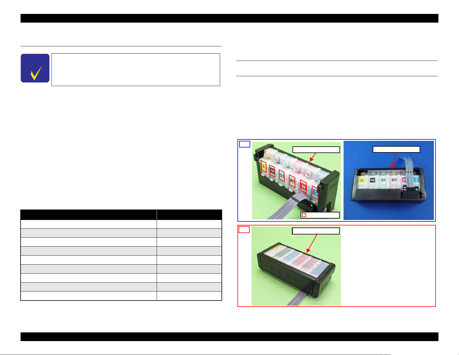
HOW TO PLACE THE INK TANK ASSY WHEN DISASSEMBLING/
REASSEMBLING
The film under sealing film attached on the Ink Supply Tank Assy of this
printer is ventilation film. The ink in the ink tanks is vented to atmosphere
through this film to keep ink supply to the Printhead stable. If the film gets wet
with ink, the ink in the tanks is not properly vented and printing may not be
capable.
In order to prevent this from occurring, make sure to place the Ink Supply Tank
Assy as shown below after removing it.
OK
Ink Supply Tank Assy
Ink Supply Tank Assy
Tool Part No.
Phillips Screwdriver (No.1) 1080530
Phillips Screwdriver (No.2) ---
Flathead Screwdriver ---
Precision Screwdriver #1 (flathead) ---
Tweezers ---
Long-nose pliers ---
Acetate tape 1003963
2 pins (thinner than Ø2 mm) ---
Strong tape 1032813
Note : All of the tools listed above are commercially available. EPSON provides the tools
listed with EPSON tool code.
NG
Figure 1-1. How to Place the Ink Tank Assy
Ventilation film
Ink Supply Tank Assy
Do not place the Ink Supply Tank Assy with
its film side down. Otherwise, ink in the Ink
Supply Tank Assy may reach and cover the
ventilation film, and the printing failure may
occur.
Disassembly/Reassembly Overview 10
Confidential
Page 11
L800/L801 Revision A
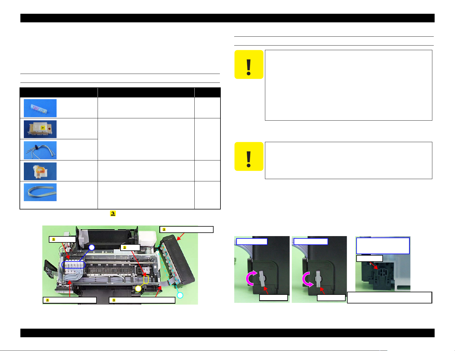
1.1.2.2 Factors which Affect the Safety of Service Personnel such as
Ink Leakage during Operation
Ink may spill when removing the following parts from L800/L801.
This section describes the parts that may cause ink spill and the means to
minimize the ink spill when removing the parts.
THE PARTS THAT MAY CAUSE INK SPILL WHEN REMOVING
Parts When ink may spill Location
Joint Removing the Ink Supply Tank Tube Assy
/ Ink Supply Tube Assy from the Joint
Ink Supply
Tank Assy
Ink Supply
Tank Tube Assy
(w/Valve Assy)
Adapter Removing the Ink Supply Tube Assy from
Ink Supply
Tube Assy
Note : These parts are indicated with the icon in disassembly/reassembly flowchart. (See
“ 1.2 Disassembly/Reassembly Procedures (p17)”.)
Removing the tubes of the Ink Supply
Tank Tube Assy from the Joint
Removing the tubes of the Ink Supply
Tank Tube Assy from the Ink Supply
Tank Assy
the Adapter
Removing the Ink Supply Tank Tube Assy
/ Ink Supply Tube Assy from the Joint
Removing the Ink Supply Tube Assy
from the Adapter
Ink Supply Tank Assy
A
A, B
C
A, C
MEANS DO TO MINIMIZE THE INK SPILL
C A U T I O N
Even observing the points described in this section, ink may
spill in the following situations. Therefore, be careful not to
contaminate the inside of the printer or its surroundings by
preparing the container to receive the leaked ink, or the like.
When removing the Ink Supply Tank Tube Assy (w/
Valve Assy), some ink will spill from both ends of the
tube even the Valve Lever is closed.
When removing the Ink Supply Tube Assy, all the ink in
the tube will spill.
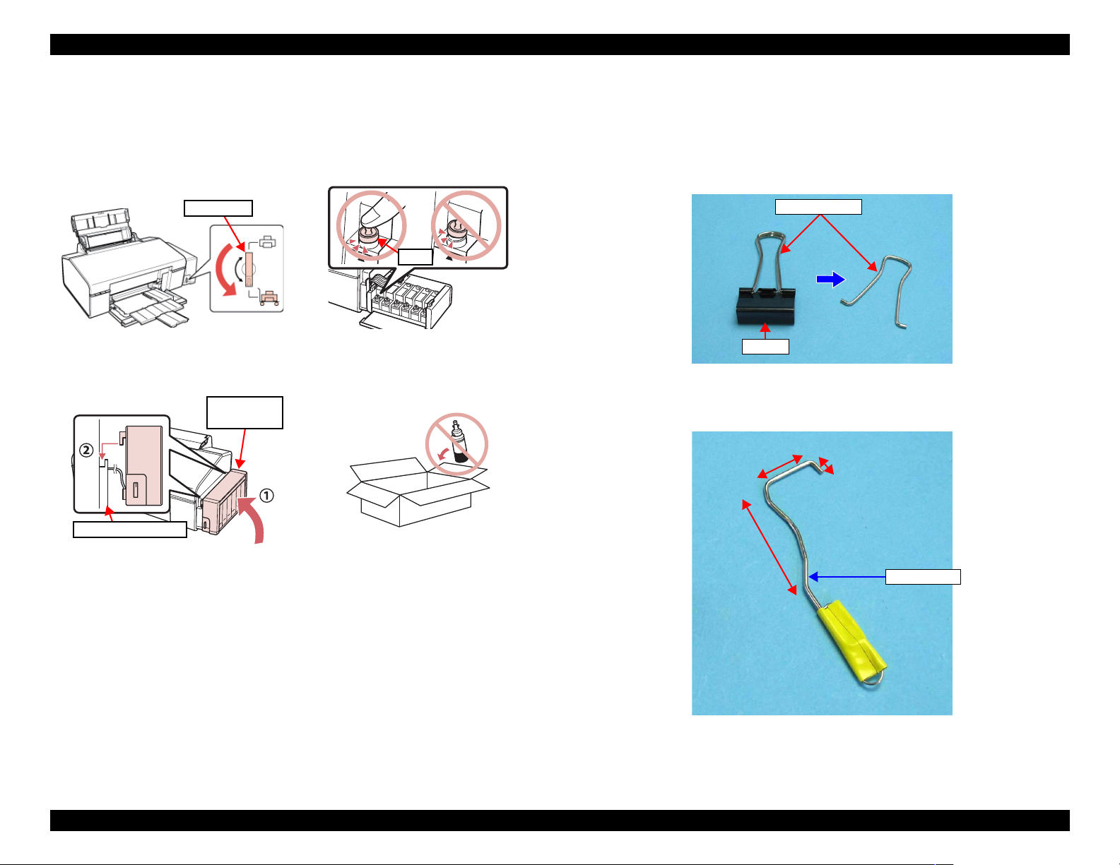
Before disassembling, confirm that the printer is in the following condition.
Choke Valve is closed
C A U T I O N
Do not turn the Valve Lever too much when closing the
Choke Valve, otherwise, the Valve Lever and/or Valve Assy
may get damaged.
Before disassembling:
Turn the Valve Lever and be sure to close the Choke Valve.
After reassembling is complete:
Open the Choke Valve to perform the print inspection.
Before returning the printer to the user after repairing:
Make sure to turn the Valve Lever up to the choke position to close the Choke
Valve before packing the printer.
Adapter
C
Joint
A
Ink Supply Tank Tube Assy Ink Supply Tube Assy
Figure 1-2. Location
Open position
Open position
B
Valve Lever
Valve Lever
Choke position
Valve Lever
Figure 1-3. Opening/closing the Choke Valve
Choke position
(When checking with the
Valve Lever removed.)
Valve shaft
Choke Valve shaft is secured more tightly
in Choke position than in Open position.
Disassembly/Reassembly Overview 11
Confidential
Page 12
L800/L801 Revision A
Adapter is removed
Before disconnecting the joint parts of the ink path, make sure that the Adapter
is removed from the Carriage.
Adapter
Carriage
Ink path
Ink valve
Figure 1-4. Adapter
C H E C K
P O I N T
The Adapter has an ink valve which cuts off the ink path
when removing the Adapter from the Carriage.
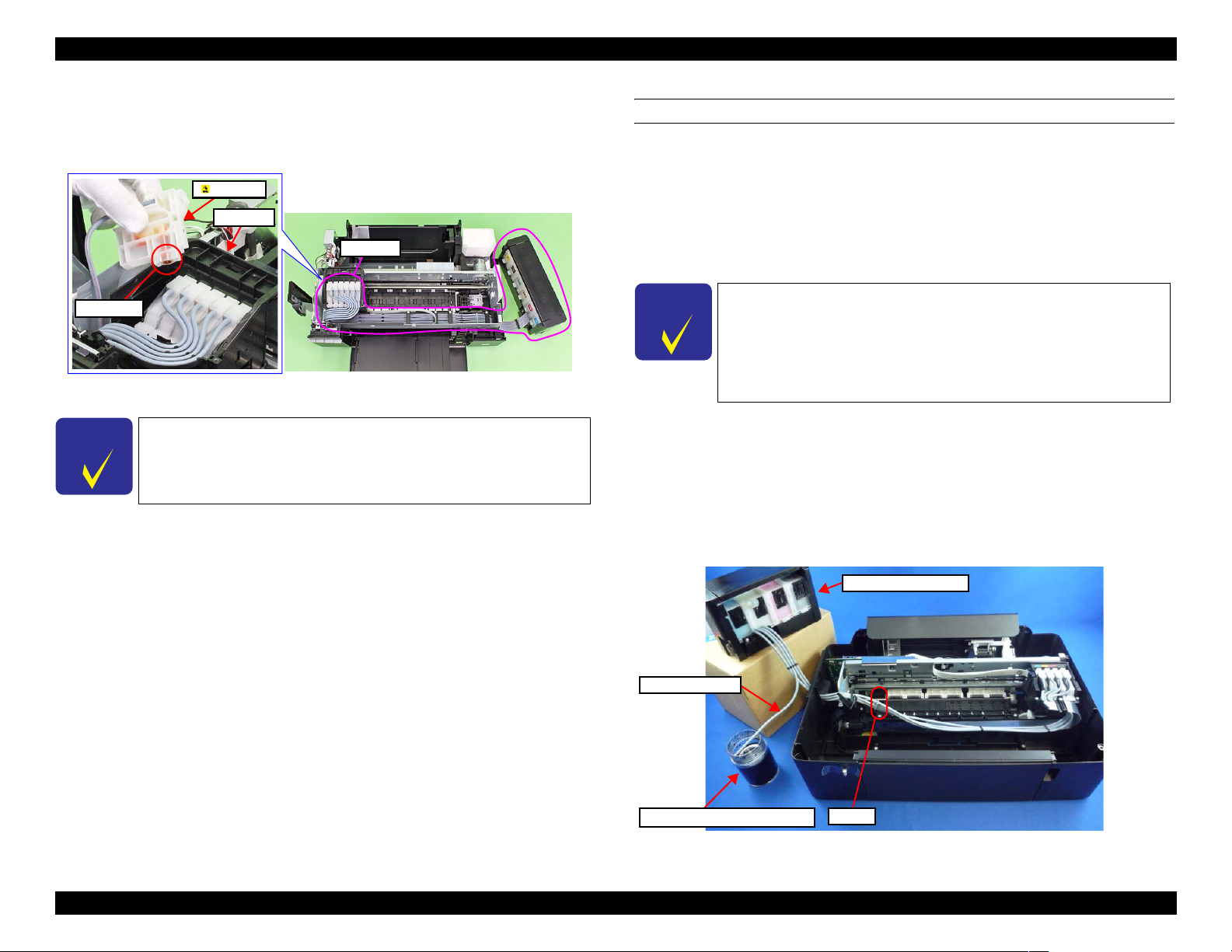
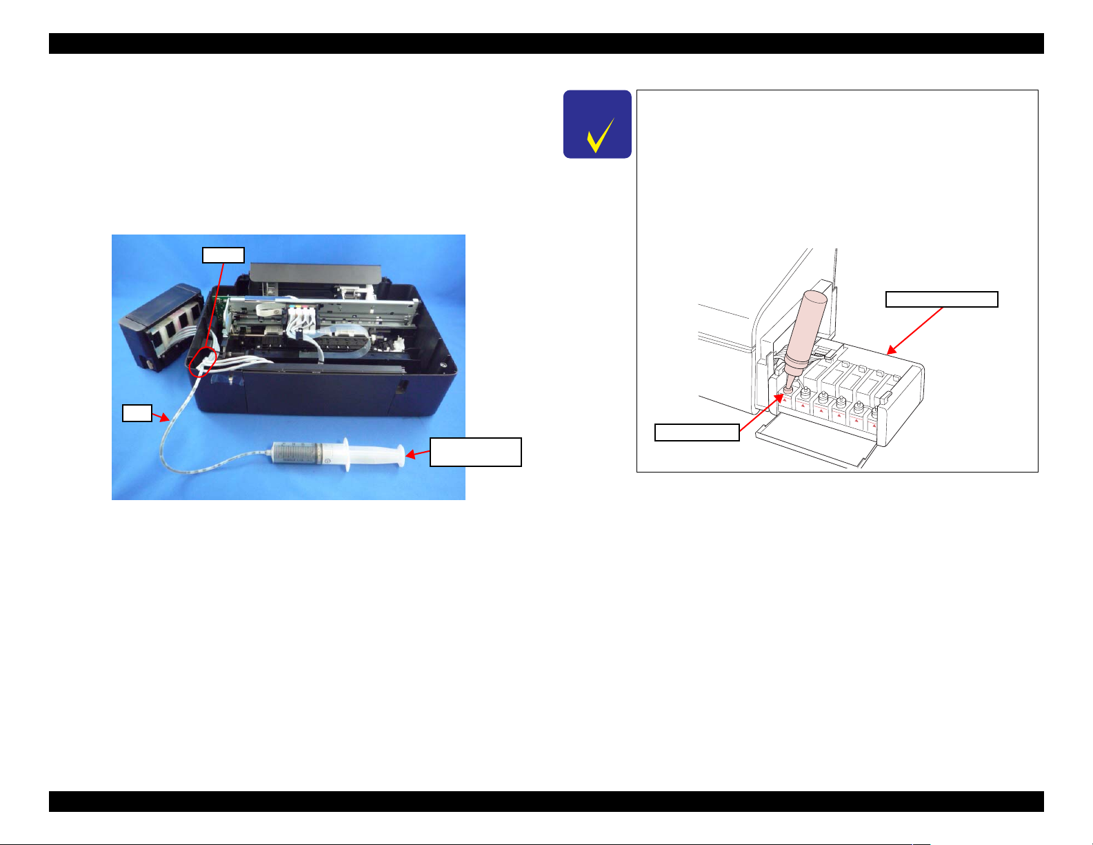
DISCHRGING INK FROM THE INK SUPPLY TANK
Discharging ink is recommended only when disconnecting the Ink Supply Tank
Tube Assy from the Ink Supply Tank. Before performing the above
disconnection, discharge ink from the Ink Supply Tank as follows.
Necessary tools
• Containers (x 6) for each discharged ink
• Injector (with a tip of φ3.2 mm)
• Tube (capable to be connected to the joint)
C H E C K
P O I N T
Discharging procedure
The photos in the following procedure are for L200/L201, but
the procedure for L800/L801 is the same; the numbers of the
tube and the location of the Ink Supply Tank Assy in the
photos are different from those of L800/L801, though.
Prior to the following steps, connect the injector with the tube,
and then discharge ink according to the procedure.
1. Remove the Housing Upper Assy. (p. 25)
2. With the choke value closed (p.11), place the Ink Supply Tank Assy on a
place where its bottom is higher than the top of the Printhead.
3. Prepare a container for ink to discharge, then disconnect the Ink Supply
Tube from the joint and put its tip into the container for the ink.
4. Open the choke valve to discharge the ink in the Ink Supply Tank Assy to
the container.
Ink Supply Tank Assy
Ink Supply Tube
Container for discharged ink
Joint
Figure 1-5. Discharging Ink (1)
Disassembly/Reassembly Overview 12
Confidential
Page 13
L800/L801 Revision A
5. When the ink stops flowing from the tube, close the choke valve, and
then connect the Ink Supply Tube back to the joint.
6. Disconnect the Ink Supply Tube of the same color connected to the
opposite side of the joint.
7. Connect the tube from the injector.
8. Open the choke valve again, and suck up the remaining ink in the Ink
Supply Tank into the injector.
9. Disconnect the tube from the injector, and connect the Ink Supply Tube
of the same color back to the joint.
Joint
Tube
Injector
(tip of
φ 3.2 mm)
C H E C K
P O I N T
It is recommended that the ink in the Ink Supply Tank should
be discharged completely before proceeding to disassembling/
reassembling.
After all the reassembling work is complete, the discharged ink
of each color should be refilled back to the Ink Supply Tank
before performing the adjustment. Confirm the colors
indicated on the film of the Ink Supply Tank so as not to
mistake them, and make sure to refill each ink back to the
correct tank from the corresponding ink supply hole.
Ink Supply Tank Assy
Ink supply hole
Figure 1-6. Discharging Ink (2)
10. Repeat Step 3 to Step 10 for all ink tanks to discharge all ink in the Ink
Supply Tank.
Disassembly/Reassembly Overview 13
Confidential
Page 14
L800/L801 Revision A
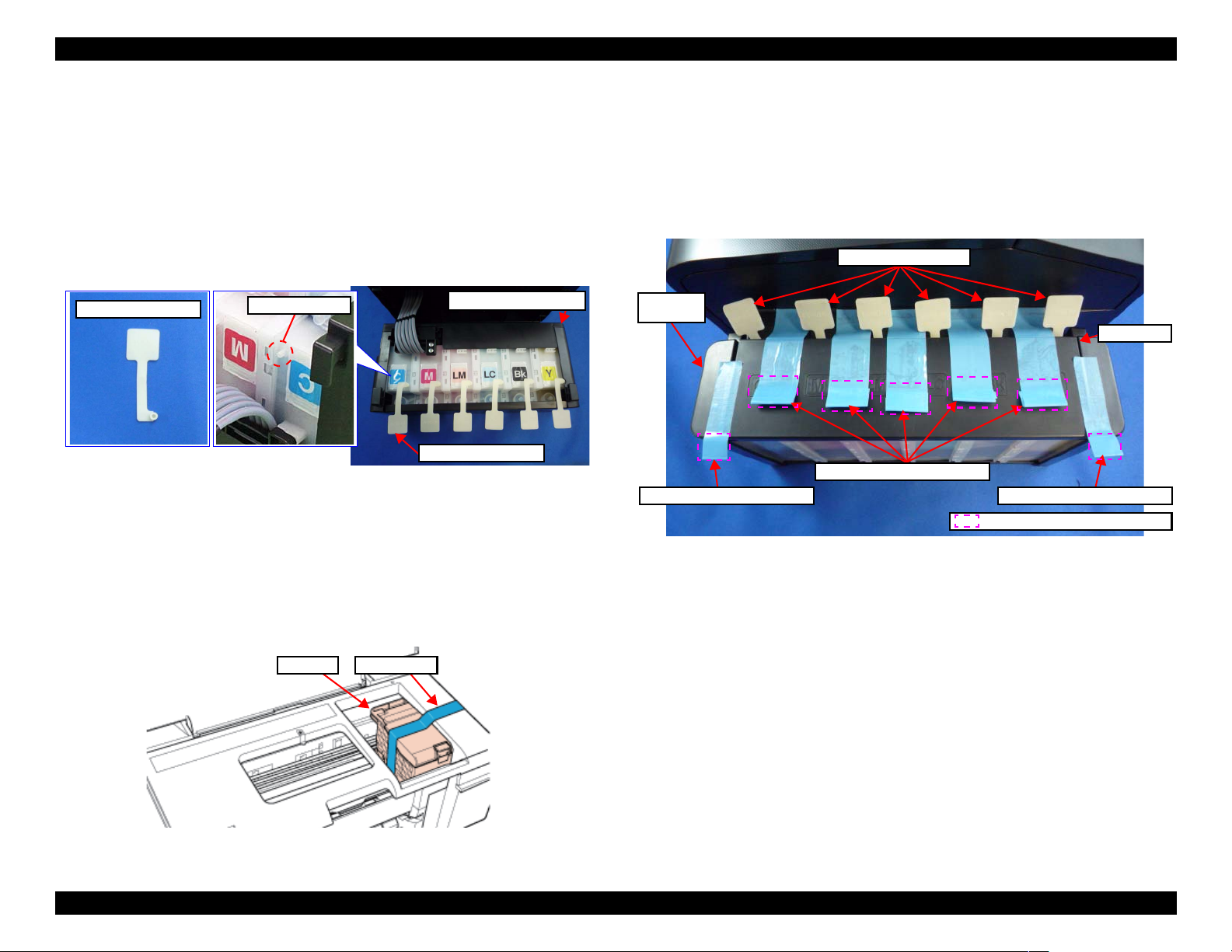
1.1.3 Protection for Transportation
Before packing the printer for returning it to the user, secure it at the specified
points with strong tape to avoid damaging the printer or ink leakage during
transport, and make sure to check the points as follows.
Attaching the Air Release Hole Caps
To prevent the ventilation film from getting wet, attach the Air Release
Hole Caps (part number: 1556135) to the air release holes of the Ink Supply
Tank Assy.
Air Release Hole Cap
Air release hole
Figure 1-7. Attaching the Air Release Hole Caps
Securing each parts
Secure the following parts with strong tape (width: 22 mm).
Securing the CR Unit
1. Confirm that the CR Unit is locked in the home position.
2. Attach the unfolded end of strong tape (fold the other end back 10 mm)
on the bottom left of the Adapter Cover.
3. Pull the tape to the right side of the housing and attach it tightly.
Ink Supply Tank Assy
Air Release Hole Cap
Securing the Ink Tank
• Secure both sides of the Top Cover with strong tape (x2).
• Align the unfolded end of strong tape (x5) with the edge of the
Housing Upper, and attach the tape along the shape of the Housing
Upper/Ink Supply Tank Assy through the openings between the Air
Release Hole Caps.
Ink Supply
Tank Assy
Strong tape (60 mm x 22 mm)
Figure 1-9. Securing the Ink Supply Tank Assy
Air Release Hole Cap
Top Cover
Strong tape (80 mm x 22 mm)
Strong tape (60 mm x 22 mm)
Fold over the tape edge by 10 mm
Strong tapeCR Unit
Figure 1-8. Securing the CR Unit
Disassembly/Reassembly Overview 14
Confidential
Page 15
L800/L801 Revision A
Points to be checked before packing the printer
The Valve Lever is on the position
shown below (the Choke Valve is
All the caps of the Ink Supply Tank
Assy are securely closed.
closed). (See Figure 1-3.)
Valve Lever
The hooks (x2) of the Ink Supply
Tank Assy are securely engaged
The opened ink bottle is not
included in the box.
with the Housing Upper Assy.
Ink Supply
Tank Assy
Cap
1.1.4 Making a Special Tool for Holder Contact
The Holder Contact (refer to p.38) can be easily removed by using a special
tool. The method for making the tool is described below.
1. Prepare a handle part of a clip, or a similar metal wire piece.
Handle part
Clip
Figure 1-10. Making Special Tool for Holder Contact (1)
2. Bend the metal wire as shown below.
25mm
7mm
Housing Upper Assy
50mm
Special Tool
Figure 1-11. Making Special Tool for Holder Contact (2)
Disassembly/Reassembly Overview 15
Confidential
Page 16
L800/L801 Revision A
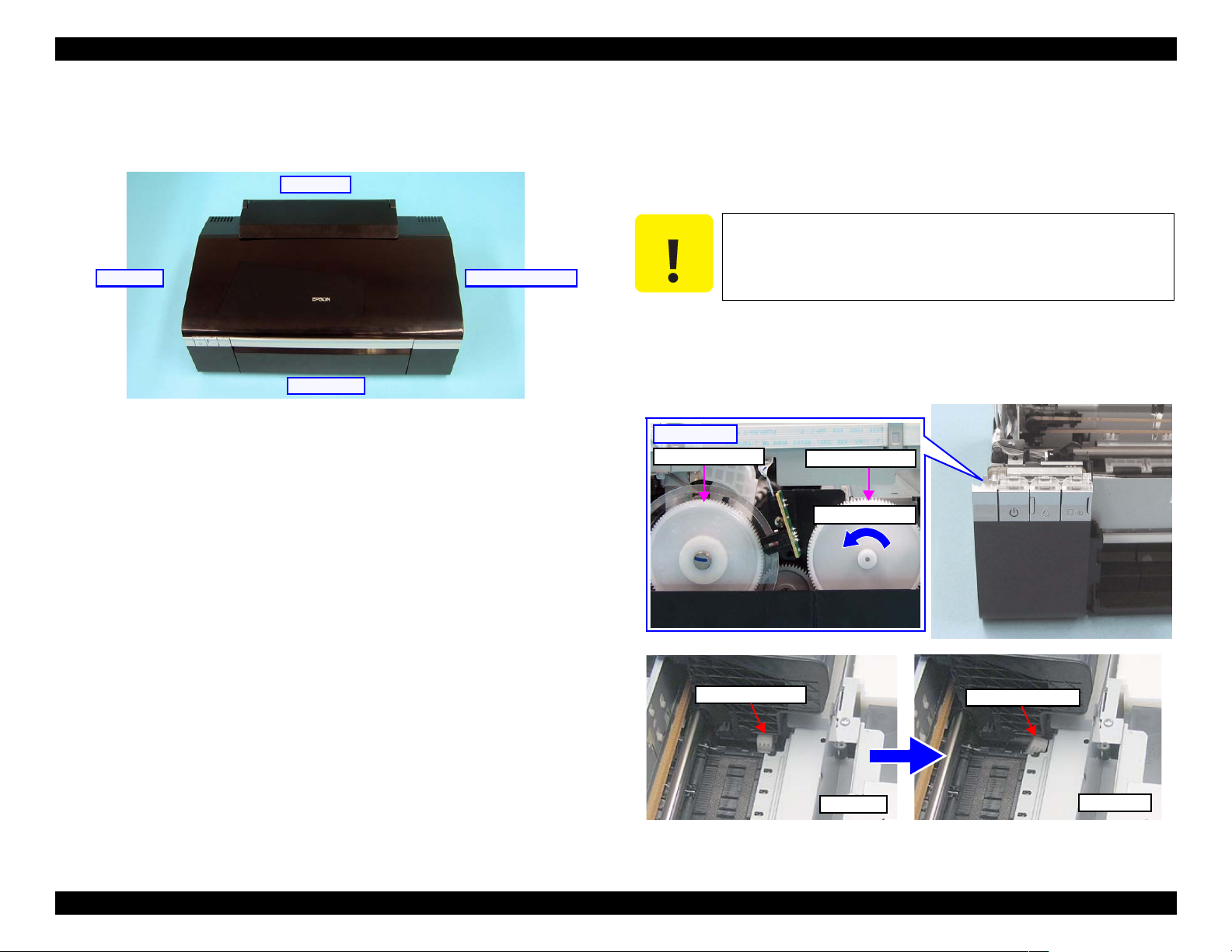
1.1.5 Orientation Definition
Orientation descriptions used in the disassembly/reassembly procedures are as
follows.
[Rear Side]
[Left Side] [Right (home) Side]
[Front Side]
Figure 1-12. Orientation Definition
1.1.6 How to Unlock the Carriage
Unlocking the carriage is required for disassembly of some parts or
components. Carry out any of the following operations to unlock the carriage
and move the carriage to other than its home position.
C A U T I O N
Power the printer and turn it off forcedly by disconnecting the power cable
Turn the EJ Roller gear on the left side of the printer in the direction of the
[Left side]
PF Roller Gear
Be extremely careful not to damage the EJ Roller gear. Extra care
must be taken to avoid injury from sharp metal edges.
when the CR Unit is unlocked and moved away from the home position.
arrow until the carriage is unlocked.
EJ Roller Gear
Turn this gear
Carriage Lock
Locked
Carriage Lock
Unlocked
Figure 1-13. How to Unlock the Carriage
Disassembly/Reassembly Overview 16
Confidential
Page 17
L800/L801 Revision A
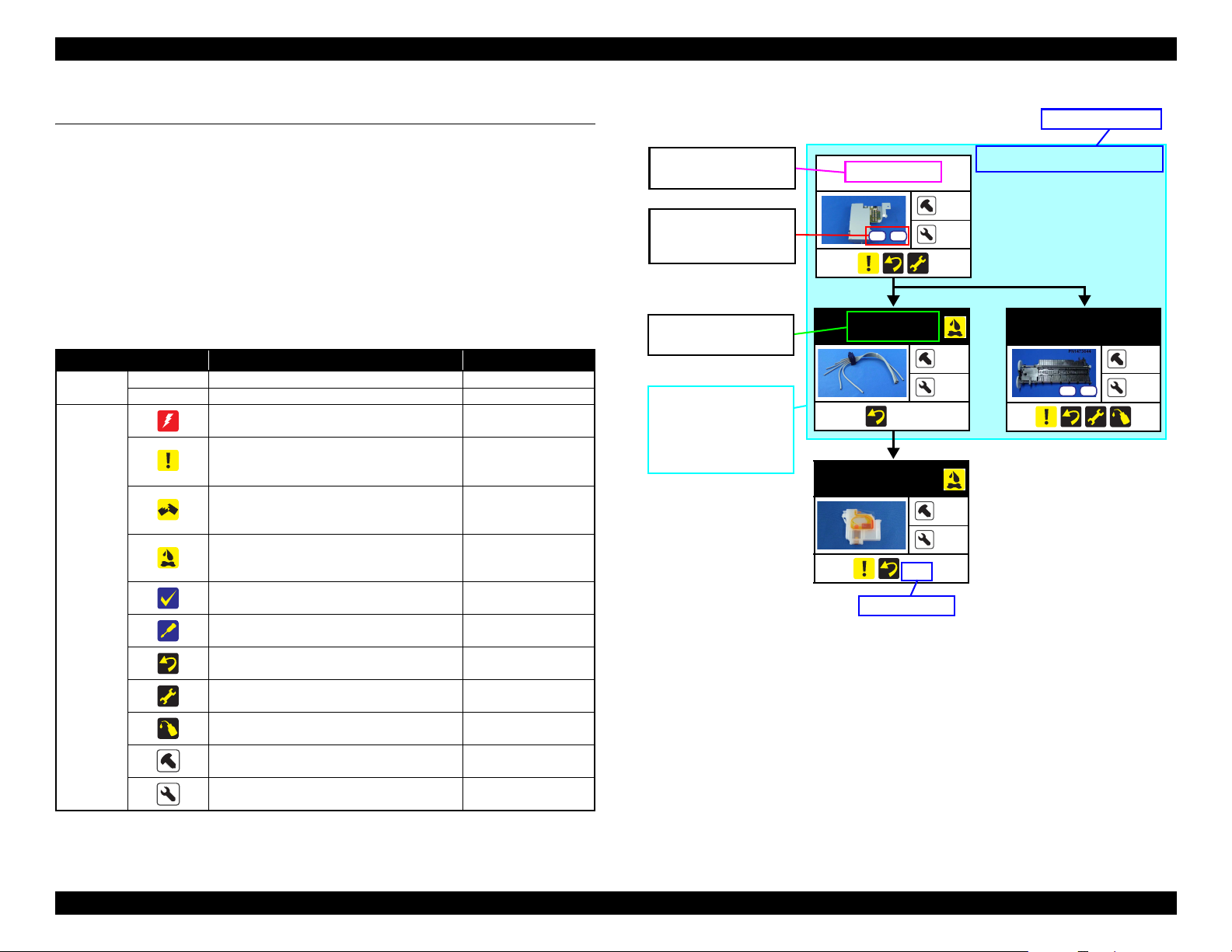
1.2 Disassembly/Reassembly Procedures
1.2.1 Overview
This section describes procedures for disassembling the parts/units in a
flowchart format. For some parts/units, detailed procedures or precautions are
provided (accordingly indicated by icons and cell's color). Refer to the
explanations in the example chart below and perform an appropriate
disassembling and reassembling procedure. (See“ 1.3 Removing Exterior
Parts/Components (p24)”.)
The example below shows how to see the charts on the following pages.
Table 1-2. Explanatory Note
Item Description Reference
Parts/unit
name
Icon
White-letter Parts/units supplied as an ASP --Black-letter Parts/units not supplied as an ASP ---
Indicates a practice or condition that could result
in injury or loss of life if not strictly observed.
Indicates a practice or condition that could result
in damage to, or destruction of equipment if not
strictly observed.
Indicates the parts that are inevitably broken in
the disassembling procedure, and should be
replaced with a new one for reassembly.
Indicates the parts that may cause the ink spill
when they are removed.
Indicates necessary check items in the
disassembling/reassembling procedure.
Indicates supplementary explanation for
disassembly is given.
Indicates particular tasks to keep quality of the
units are required.
Indicates particular adjustment(s) is/are required.
Indicates lubrication is required.
Indicates the number of screws securing the
parts/units.
Indicates the points secured with other than a
screw such as a hook, rib, dowel or the like.
Indicates the reference
page in blue-letter
Indicates the reference
page in blue-letter
“ 1.1.2 Checks and
Precautions before
Disassembling (p10)”
Indicates the reference
page in blue-letter
Indicates the reference
page in blue-letter
Indicates the reference
page in blue-letter
Chapter 2 “ Adjustment
(p69)”
Chapter 3 “
Maintenance (p88)”
---
---
---
Black letters indicate a
part/unit not supplied as
an ASP.
Shows the screw types
and the specified torque
in the “Screw type/torque
list”.
White letters indicate a
part/unit supplied as an
ASP.
Indicates that the
disassembly procedure of
boxed parts is explained
all together and step by
step in the section shown
as reference page (A).
Main Board Unit
3
S7
S15
Ink Supply Tank
Tube Assy
(p 20)
Adapter
(p 18)
Reference page
---
---
---
---
1
Figure 1-14. Example Chart
Reference page (A)
“ 1.5.8 Ink System (p45)”
Front Paper
Guide Assy
S15
S9
2
1
Disassembly/Reassembly Disassembly/Reassembly Procedures 17
Confidential
Page 18
L800/L801 Revision A
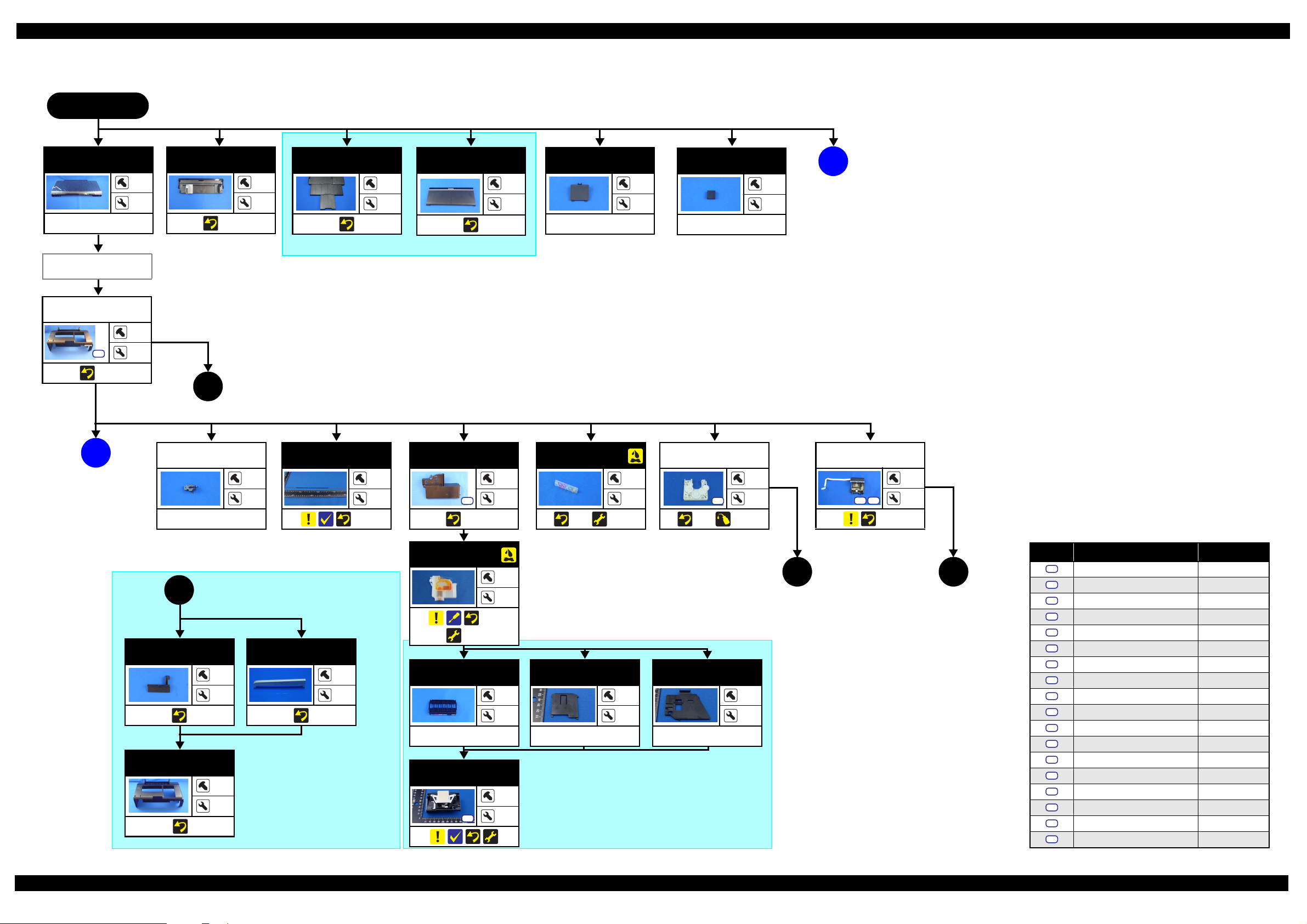
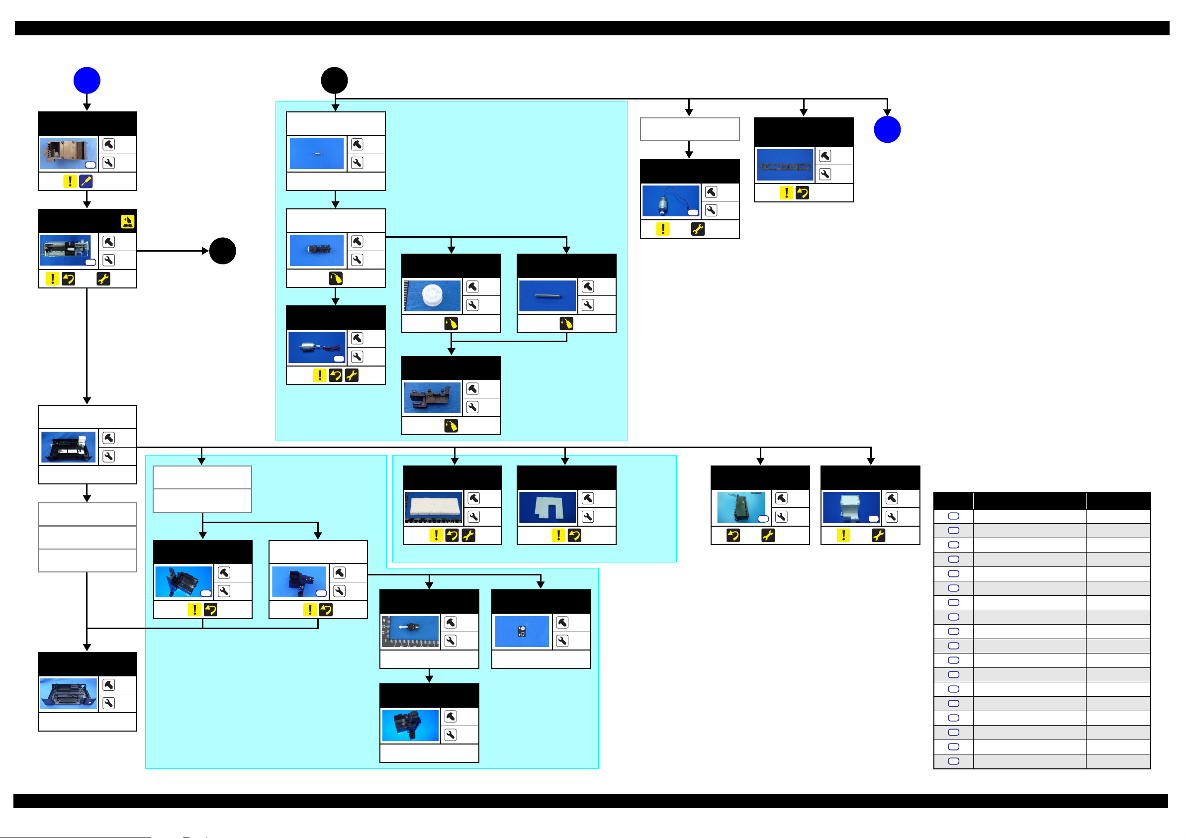
1.2.2 Disassembly Flowchart
START
Printer Cover
(p 24)
Paper Support
Assy
Housing Upper
Assy
S4
(p 25)
(p 20)
B
---
---
4
Paper Support
Assy
---
2
(p 24)
2
Stacker Assy
---
Stacker Cover
---
2
2
Cover Ink Tube
(p 35)
Foot
---
1
---
---
---
A
(p 19)
“ 1.3.3 Stacker Assy / Stacker Cover (p25) ”
(p 18)
1
Cover Open
Sensor
CR Scale
Adapter Cover
Joint
APG Unit
Panel Assy
(p 18)
1
Housing Right
Housing Upper
---
2
(p 30)
(p 40)
“ 1.3.4 Housing Upper Assy (p25)”
Decoration Belt
Right
---
2
---
---
---
1
2
S6
(p 68)
3
(p 65) (p 69)
---
2
2
S15
(p 41) (p 88)
---
S4
S14
(p 30)
2
1
Screw type/torque list
Adapter
---
(p 19)
2
(p 19)
3
1
(p 68)
(p 69)
---
2
Holder Contact
---
2
---
Cover FFC Inner
---
Cover FFC
---
1
---
---
1
Printhead
3
S2
---
“ 1.5.2 Printhead (p37)”
Symbol Screw type Torque
S1
C.B.P. 2.6X8 3.5-4.5kgf.cm
S2
C.B.P. 2.6X8 3-5kgf.cm
S3
C.B.P. 3X10 3-5kgf.cm
S4
C.B.P. 3X10 5-7kgf.cm
S5
C.B.P. 3X6 3-5kgf.cm
S6
C.B.P. 3X8 5-7kgf.cm
S7
C.B.P.(P2) 3X8 5-7kgf.cm
S8
C.B.S 3X6 5-7kgf.cm
S9
C.B.S. (P2) 3X8 6-8kgf.cm
S10
C.B.S. (P4) 3X6 7-9kgf.cm
S11
C.B.S. (P4) 3X6 9-11kgf.cm
S12
C.B.S. 3X10 4-6kgf.cm
S13
C.B.S. 3X6 4-6kgf.cm
S14
C.B.S. 3X6 5-7kgf.cm
S15
C.B.S. 3X6 7-9kgf.cm
S16
C.P. 3X4 3-5kgf.cm
S17
C.P. 3X6 3-5kgf.cm
S18
C.P. 3X6 4-6kgf.cm
Disassembly/Reassembly Disassembling/Reassembling Flowchart 18
Confidential
Page 19
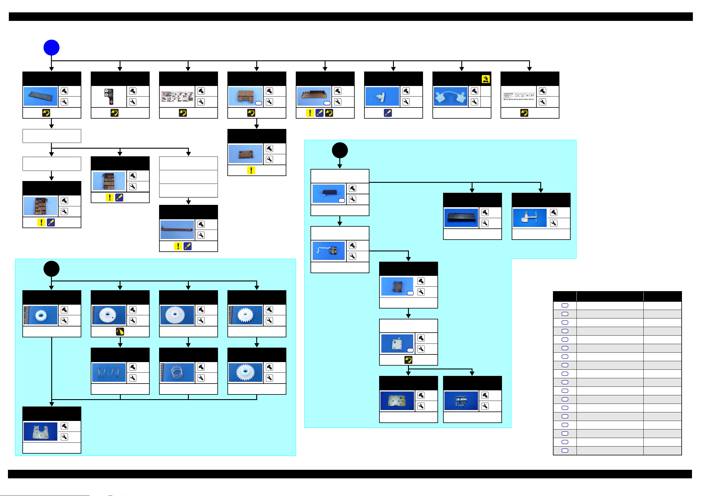
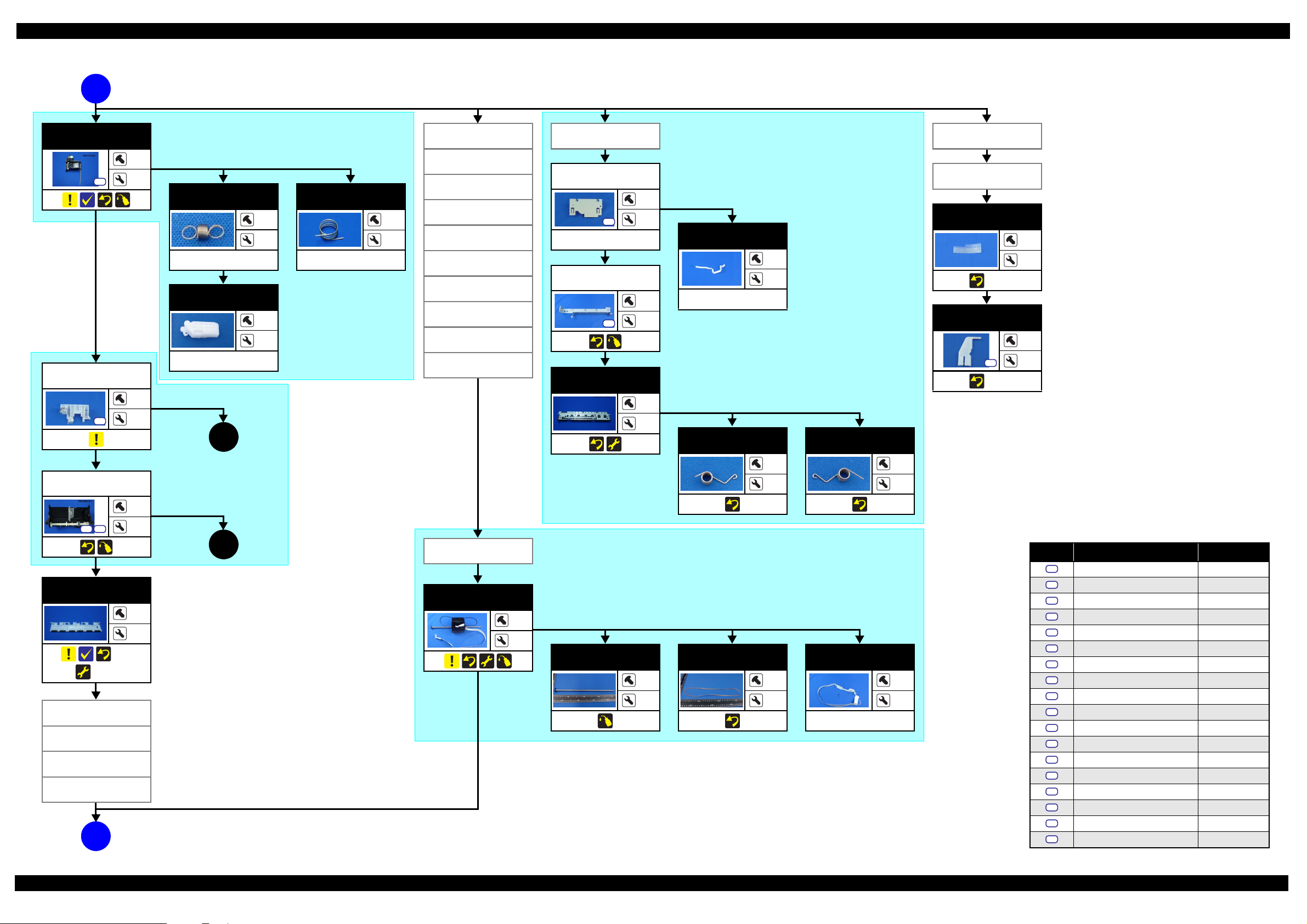
L800/L801 Revision A
(p 18)
A
Top Cover
(p 61)
Bottom Cover
Valve Leve r
Right Cover
(p 63)
2
(p 18)
Valve Posi t i o n
Label
---
2
(p 61)
---
---
Refilling Ink
Label
(p 61)
---
---
Tube Valve
Holder Rear
S5
(p 62)
Bottom Cover
3
6
S5
(p 63)
8
---
Valve Leve r
---
2
(p 62)
Cap
---
---
---
Top Cover Label
---
---
(p 61)
Tube Valve
Holder Front
---
Left Cover
---
7
---
(p 63)
7
Left Cover
(p 62)
Valve Le v e r
Right Cover
Cover Joint
---
Panel Cover
3
Assy
---
(p 18)
2
S3
---
---
2
(p 63)
Panel Unit
---
“ 1.4.2 Panel Assy/ Cover Open Sensor (p30)”
Panel Cover
---
---
---
Decoration Belt
Left
---
---
---
---
“ 1.5.4 APG Unit (p41)”
---
Open Sensor
Holder
Spur Gear 12.8
---
APG Holder
---
1
Spur Gear 28.8
---
---
---
---
Spur Gear 33.6
---
---
---
Combination
Gear 14.22
---
---
---
S3
---
Panel Shield
Plate
4
2
Compression
Spring 2.25
---
---
---
Compression
Spring 0.97
---
Combination
S3
Gear 12.8.27
---
---
---
---
---
Panel Board
---
---
Housing Panel
Assy
---
1
---
---
---
---
---
Screw type/torque list
Symbol Screw type Torque
S1
C.B.P. 2.6X8 3.5-4.5kgf.cm
S2
C.B.P. 2.6X8 3-5kgf.cm
S3
C.B.P. 3X10 3-5kgf.cm
S4
C.B.P. 3X10 5-7kgf.cm
S5
C.B.P. 3X6 3-5kgf.cm
S6
C.B.P. 3X8 5-7kgf.cm
S7
C.B.P.(P2) 3X8 5-7kgf.cm
S8
C.B.S 3X6 5-7kgf.cm
S9
C.B.S. (P2) 3X8 6-8kgf.cm
S10
C.B.S. (P4) 3X6 7-9kgf.cm
S11
C.B.S. (P4) 3X6 9-11kgf.cm
S12
C.B.S. 3X10 4-6kgf.cm
S13
C.B.S. 3X6 4-6kgf.cm
S14
C.B.S. 3X6 5-7kgf.cm
S15
C.B.S. 3X6 7-9kgf.cm
S16
C.P. 3X4 3-5kgf.cm
S17
C.P. 3X6 3-5kgf.cm
S18
C.P. 3X6 4-6kgf.cm
Disassembly/Reassembly Disassembling/Reassembling Flowchart 19
Confidential
Page 20
L800/L801 Revision A
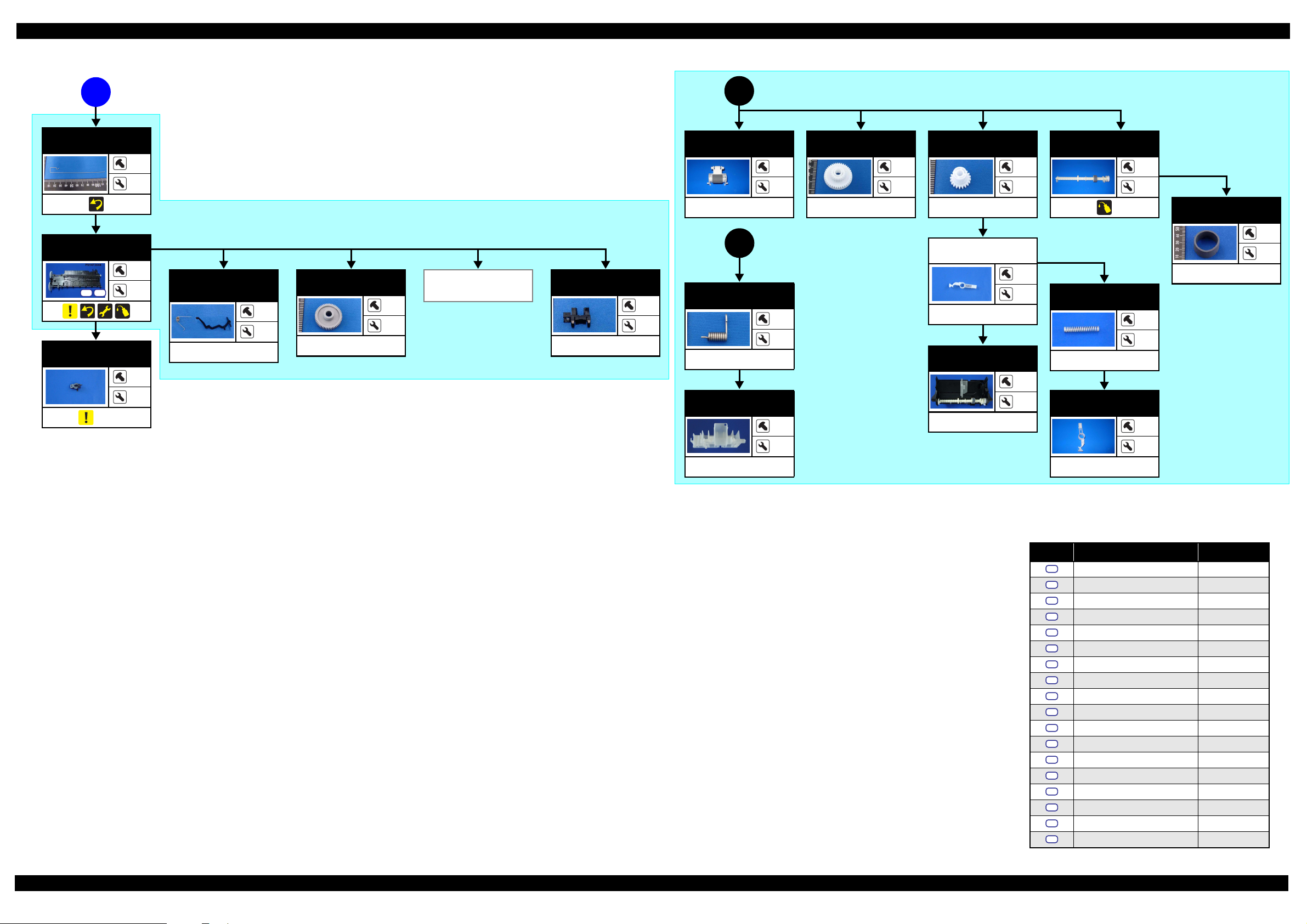
(p 18)
B
Main Board Unit
S7
S15
“ 1.4.1 Main Board Unit (p27) ”
Tube H o l d e r*
*: There are four Tube Holders installed in this printer. Depending on the target parts or units, the number of
Tube Holders you should remove differs.
3
---
Upper Shield
Plate M/B
S6
---
7
S14 S18
Shield Plate M/B
Sub
S13
---
Lower Shield
Plate M/B
2
---
S13
2
---
Ink Supply Tank
Assy
(p 64) (p 69)
Main Board
1
S12
---
1
1
When removing the Ink Supply Tank Assy: The Tube Holder on the home position side (on the Cover Case)
When removing the Printer Mechanism: All Tube Holders
Adapter CoverAdapter Cover
---
---
Ink Supply Tank
Tube Assy
---
---
(p 64) (p 69)
Top Cover
Adapter
Joint
Ink Supply Tube
Assy (W/Clamp)
(p 67) (p 69)
Tube Guide
Sheet
---
3
---
(p 66)
---
Tube Guide
Tube Guide
Sheet Sub
---
1
---
4
(p 66)
Bottom Cover
---
Valve Le v e r
Cover Ink Tube
Panel Assy
Tube Holder
Ink Supply Tank
Assy
Adapter Cover
Adapter
Tube Guide
Sheet/Tube
Guide Sheet Sub
(p 21)
C
APG Sensor
Assy
---
2
---
Photo Interrupter
---
2
---
“ 1.5.16 APG Sensor Assy
(p57)”
PF Encoder
S1
PF Scale
1
---
---
---
“ 1.5.10 PF Encoder / PF Scale (p49)”
Right Cover
Left Cover
Cover Joint
Tube Valve
Holder Rear
Tube Valve
Holder Front
Ink Supply Tank
(p 64) (p 69)
Screw type/torque list
Symbol Screw type Torque
S1
C.B.P. 2.6X8 3.5-4.5kgf.cm
S2
C.B.P. 2.6X8 3-5kgf.cm
S3
C.B.P. 3X10 3-5kgf.cm
S4
C.B.P. 3X10 5-7kgf.cm
S5
C.B.P. 3X6 3-5kgf.cm
S6
C.B.P. 3X8 5-7kgf.cm
S7
C.B.P.(P2) 3X8 5-7kgf.cm
S8
---
---
C.B.S 3X6 5-7kgf.cm
S9
C.B.S. (P2) 3X8 6-8kgf.cm
S10
C.B.S. (P4) 3X6 7-9kgf.cm
S11
C.B.S. (P4) 3X6 9-11kgf.cm
S12
C.B.S. 3X10 4-6kgf.cm
S13
C.B.S. 3X6 4-6kgf.cm
S14
C.B.S. 3X6 5-7kgf.cm
S15
C.B.S. 3X6 7-9kgf.cm
S16
C.P. 3X4 3-5kgf.cm
S17
C.P. 3X6 3-5kgf.cm
S18
C.P. 3X6 4-6kgf.cm
Disassembly/Reassembly Disassembling/Reassembling Flowchart 20
Confidential
Page 21
L800/L801 Revision A
(p 20) (p 21)
C
Cover Case
S6
(p 65)
Printer
Mechanism
S6
(p 35) (p 69)
4
Extension Spring
1
---
---
Driven Pulley
Assy
5
(p 21)
4
4
---
2
---
---
Driven Pulley
CR Motor
2
S16
---
Driven Pulley
Holder
“ 1.5.12 CR Motor (p50) ”
Driven Pulley
Shaft
---
---
---
PF Encoder/
PF Scale
Porous Pad
Paper Guide
Front
D
(p 22)
---
PF Motor
S17
(p 49) (p 69)
---
2
(p 57)
---
---
---
Housing Lower
Assy
---
Waste Ink Pad
Lower
Waste Ink Pad
Cap
P/S Assy
Housing Lower
(W/Foot)
---
---
---
---
“ 1.5.7 Left & Right Guide
Stacker Assy
Stackers / CDR Guide Sensor
(p44)”
Stacker Cover
Guide Stacker
Left
1
S6
---
---
---
Guide Stacker
Right Assy
S6
“ 1.5.6 Waste Ink Pad Lower / Waste Ink Pad Cap Lower (p43)”
1
---
Waste Ink Pad
Lower
CDR Guide
Sensor
---
Guide Stacker
Right
---
Waste Ink Pad
Cap Lower
---
---
---
---
P/S Assy
S4
(p 34) (p 69)
1
---
Label CDR
---
2
---
---
---
---
---
Waste Ink Tray
S4
(p 42) (p 69)
Screw type/torque list
2
1
Symbol Screw type Torque
S1
S2
S3
S4
S5
S6
S7
S8
S9
S10
S11
S12
S13
S14
S15
S16
S17
S18
C.B.P. 2.6X8 3.5-4.5kgf.cm
C.B.P. 2.6X8 3-5kgf.cm
C.B.P. 3X10 3-5kgf.cm
C.B.P. 3X10 5-7kgf.cm
C.B.P. 3X6 3-5kgf.cm
C.B.P. 3X8 5-7kgf.cm
C.B.P.(P2) 3X8 5-7kgf.cm
C.B.S 3X6 5-7kgf.cm
C.B.S. (P2) 3X8 6-8kgf.cm
C.B.S. (P4) 3X6 7-9kgf.cm
C.B.S. (P4) 3X6 9-11kgf.cm
C.B.S. 3X10 4-6kgf.cm
C.B.S. 3X6 4-6kgf.cm
C.B.S. 3X6 5-7kgf.cm
C.B.S. 3X6 7-9kgf.cm
C.P. 3X4 3-5kgf.cm
C.P. 3X6 3-5kgf.cm
C.P. 3X6 4-6kgf.cm
Disassembly/Reassembly Disassembling/Reassembling Flowchart 21
Confidential
Page 22
L800/L801 Revision A
(p 21)
D
Ink System
S15
LD Roller
Guide Assy
S10
2
---
Extension Spring
CR Lock
“ 1.5.14 ASF Unit (p54)”
1
5
0.8
---
---
5
---
---
---
(p 23)
“ 1.5.8 Ink System (p45)”
Compression
Spring 0.98
2
---
APG Unit
Tube Guide
“ 1.5.9 EJ Frame Assy (p46)”
Tube G u i d e
Extension Spring
Driven Pulley
Assy
Cable Holder
Frame
Cable Holder
Frame
2
---
---
CR Scale
Adapter Cover
S15
---
Adapter
Front Frame
2
PF Encoder FFC
---
---
Cover FFC
---
Cover FFC Inner
Holder Contact
S15
2
---
Printhead
EJ Frame Assy
PF Scale Sheet
(p 66)
PF Scale Cover
S6
(p 66)
---
---
1
1
---
---
EJ Frame
Torsion Spring L
---
EJ Frame
Torsion Spring R
---
ASF Unit
S10 S11
Upper Paper
Guide
(p 56)
(p 69)
Tube G u i d e
Cable Holder
Frame
Front Frame
EJ Frame Assy
E
(p 23)
---
---
2
2
(p 23)
6
Cable Holder
Frame
“ 1.5.13 CR Unit (p52)”
CR Unit
---
---
---
2
CR Guide Shaft
---
---
Timing Belt
---
---
Head FFC
---
---
---
Screw type/torque list
Symbol Screw type Torque
S1
C.B.P. 2.6X8 3.5-4.5kgf.cm
S2
C.B.P. 2.6X8 3-5kgf.cm
S3
C.B.P. 3X10 3-5kgf.cm
S4
C.B.P. 3X10 5-7kgf.cm
S5
C.B.P. 3X6 3-5kgf.cm
S6
C.B.P. 3X8 5-7kgf.cm
S7
C.B.P.(P2) 3X8 5-7kgf.cm
S8
C.B.S 3X6 5-7kgf.cm
S9
C.B.S. (P2) 3X8 6-8kgf.cm
S10
C.B.S. (P4) 3X6 7-9kgf.cm
S11
C.B.S. (P4) 3X6 9-11kgf.cm
S12
C.B.S. 3X10 4-6kgf.cm
S13
C.B.S. 3X6 4-6kgf.cm
S14
C.B.S. 3X6 5-7kgf.cm
S15
C.B.S. 3X6 7-9kgf.cm
S16
C.P. 3X4 3-5kgf.cm
S17
C.P. 3X6 3-5kgf.cm
S18
C.P. 3X6 4-6kgf.cm
Disassembly/Reassembly Disassembling/Reassembling Flowchart 22
Confidential
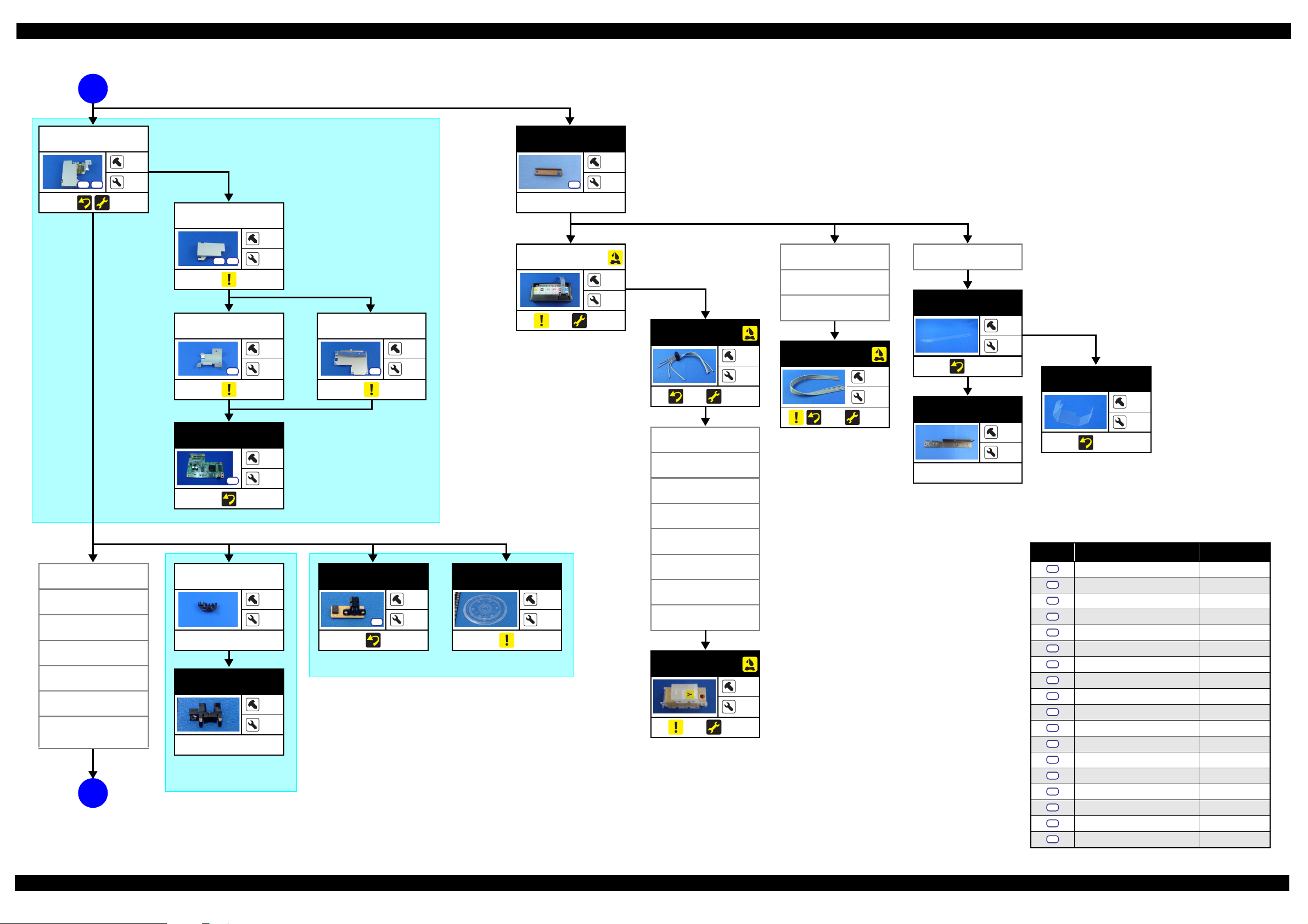
Page 23
L800/L801 Revision A
E
EJ Ground
Spring
Front Paper
Guide Assy
S9
S15
CDR Tray
Sensor
(p 60)
(p 22)
(p 22)
6
Retard Roller
Holder Assy
---
3
“ 1.5.17 Front Paper Guide Assy (p57)”
---
---
2
Combination
Gear 168.32.8
---
Spur Gear 16
---
1
---
---
---
LD Roller
Shaft Assy
“ 1.5.14 ASF Unit (p54)”
---
2
LD Roller
---
(p 22)
5
2
1
PE Lever/
PE Lever
Torsion Spring
---
---
Spur Gear 26.5
---
2
---
1
---
2
Porous Pad
Paper Guide
Front
Photo Interrupter
(PE Sensor)
---
---
Torsion Spring
137.7
4
---
---
---
LD Roller Guide
---
Change Lever
Assy
---
ASF Assy
---
---
---
---
Compression
Spring 2.36
---
---
---
---
---
---
Change Lever
---
---
---
---
1
Screw type/torque list
Symbol Screw type Torque
S1
C.B.P. 2.6X8 3.5-4.5kgf.cm
S2
C.B.P. 2.6X8 3-5kgf.cm
S3
C.B.P. 3X10 3-5kgf.cm
S4
C.B.P. 3X10 5-7kgf.cm
S5
C.B.P. 3X6 3-5kgf.cm
S6
C.B.P. 3X8 5-7kgf.cm
S7
C.B.P.(P2) 3X8 5-7kgf.cm
S8
C.B.S 3X6 5-7kgf.cm
S9
C.B.S. (P2) 3X8 6-8kgf.cm
S10
C.B.S. (P4) 3X6 7-9kgf.cm
S11
C.B.S. (P4) 3X6 9-11kgf.cm
S12
C.B.S. 3X10 4-6kgf.cm
S13
C.B.S. 3X6 4-6kgf.cm
S14
C.B.S. 3X6 5-7kgf.cm
S15
C.B.S. 3X6 7-9kgf.cm
S16
C.P. 3X4 3-5kgf.cm
S17
C.P. 3X6 3-5kgf.cm
S18
C.P. 3X6 4-6kgf.cm
Disassembly/Reassembly Disassembling/Reassembling Flowchart 23
Confidential
Page 24
L800/L801 Revision A
1.3 Removing Exterior Parts/Components
1.3.1 Printer Cover
Removal procedure
1. Pull out the left shaft and right shaft of the Printer Cover, and remove the
Printer Cover.
Printer Cover
Shaft (left)
Figure 1-15. Removing the Printer Cover
Shaft (right)
1.3.2 Paper Support Assy
Removal procedure
1. Open the Paper Support Assy.
2. Disengage the right shaft of the Paper Support Assy from the bushing of the
ASF Unit by pushing the bushing outward. Then remove the Paper Support
Assy, disengaging the left shaft preventing the Edge Guide projection from
hitting against the other parts.
Paper Support Assy
Push
Bushing of the ASF
Figure 1-16. Removing the Paper Support Assy
When reinstalling the Paper Support Assy, match the projection
and hole of the Edge Guide, then attach the right shaft and the left
shaft in that order. (Put the shafts at the front side in the bushing
and then push them rearward.) After reinstalling, check that the
Paper Support Assy moves smoothly.
Edge Guide
Projection
Paper Support Assy
:Shaft
Convex Portion
2
1
Mounting Direction
(from front side to rear side)
Hole
: Shaft
Figure 1-17. Reinstalling the Paper Support Assy
Disassembly/Reassembly Printer Cover 24
Confidential
Page 25
L800/L801 Revision A
1.3.3 Stacker Assy / Stacker Cover
Removal procedure
1. Open the Stacker Cover.
2. Remove the Stacker Assy.
3. Release the Stacker Cover from the two shafts and remove the Stacker Cover.
Shaft
Stacker Assy Stacker Cover
Figure 1-18. Removing the Stacker Assy / Stacker Cover
When installing the Stacker Assy, insert the guide pins of the
Stacker Assy into the lower grooves of the Guide Stacker Assy.
(The upper grooves are used when CDR is printed.)
Groove
Shaft
Groove
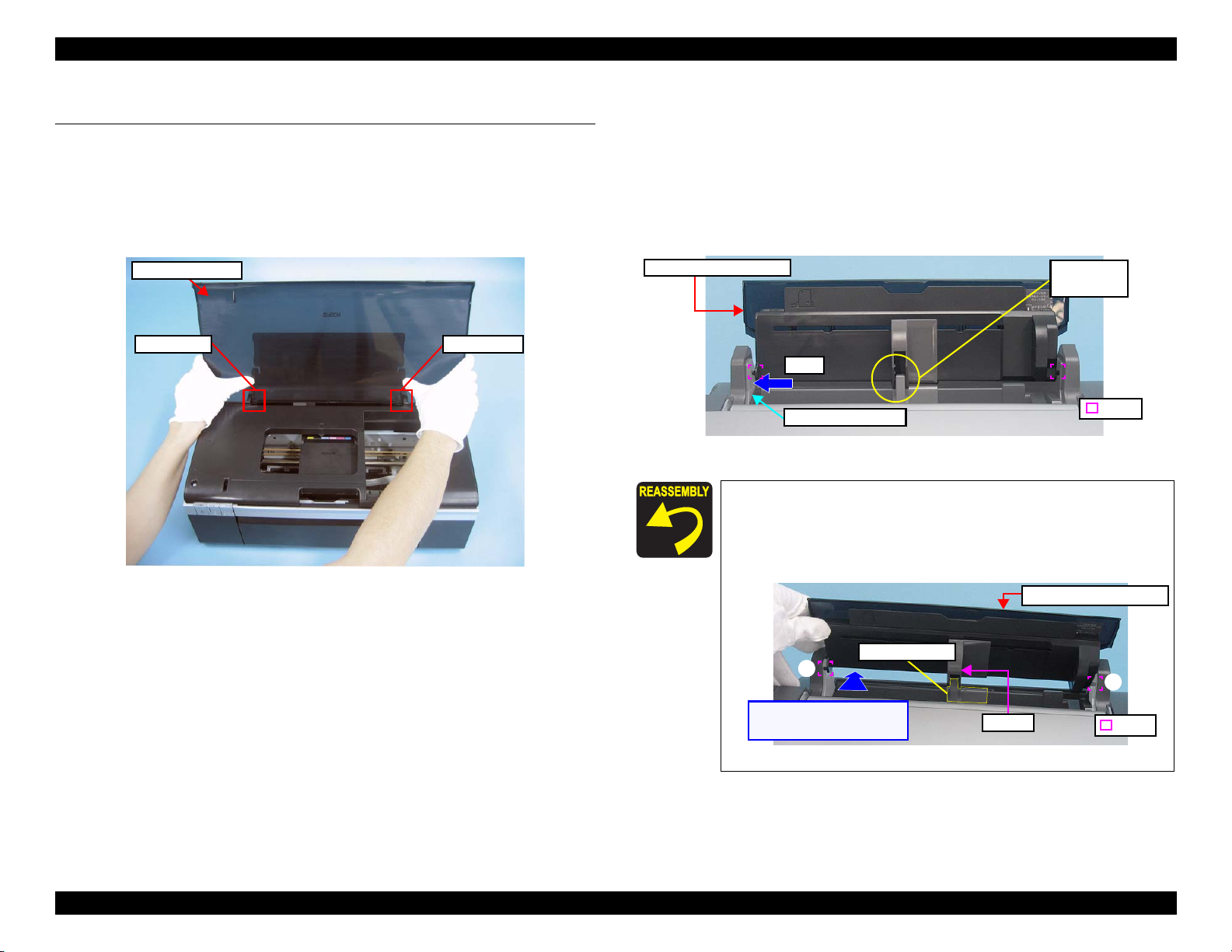
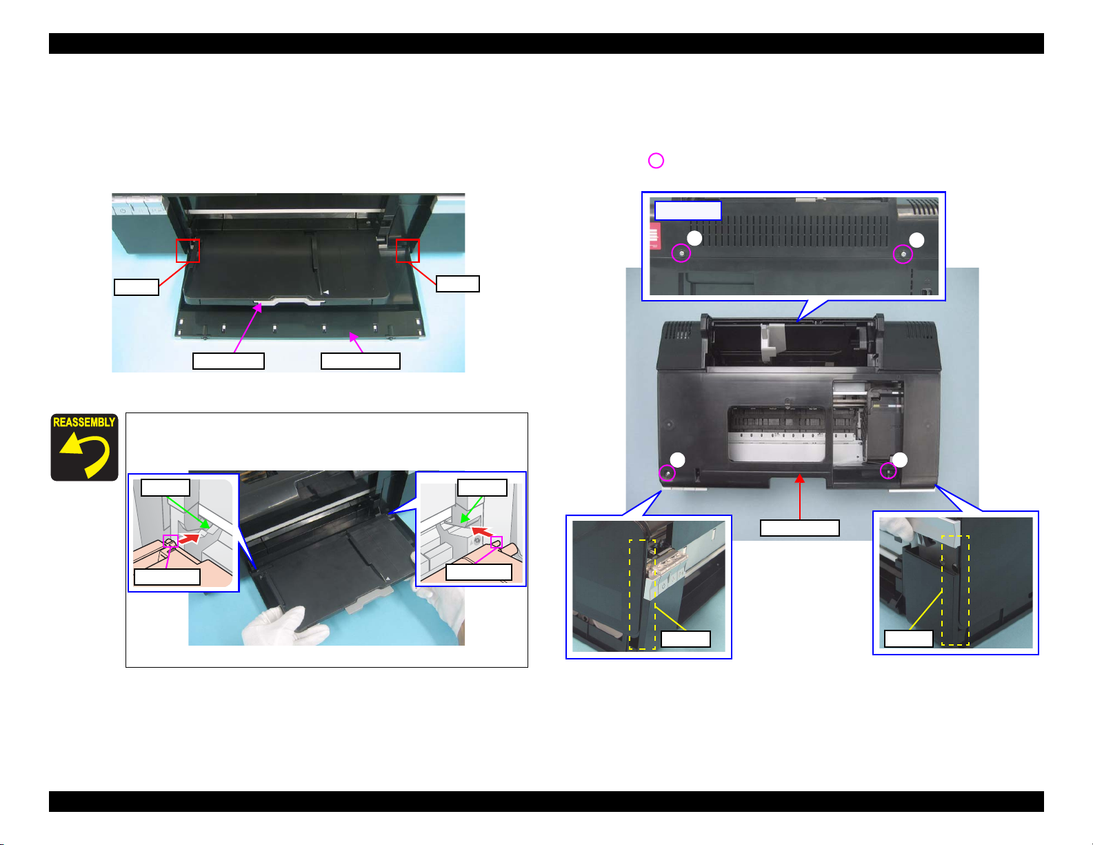
1.3.4 Housing Upper Assy
Removal procedure
1. Remove the four screws and remove the Upper Housing upward.
•
Screw : C.B.P. M3x10 (tightening torque: 5-7 kgf.cm)
(The numbers shown in the figure indicate the order of tightening the screws.)
[Rear Side]
4
1 2
3
Upper Housing
Guide Pin
Guide Pin
Groove
Groove
Figure 1-19. Installing the Stacker Assy
Figure 1-20. Removing the Upper Housing
Disassembly/Reassembly Stacker Assy / Stacker Cover 25
Confidential
Page 26
L800/L801 Revision A
2. Slide the Front Housing in the direction of the arrow and remove the Front
Housing from the Upper Housing.
Front Housing
Grooves
[Rear Side]
Ribs
Figure 1-21. Removing the Front Housing
When installing the Upper Housing, be careful of the following:
Do not pinch the cables.
Tighten the screws in the order given in Fig.1-20 (p.25).
Match the ribs of the Upper Housing shown in Fig.1-20 (p.25)
with the grooves of the Housing Lower.
As shown in Fig.1-22, match the A part of the Front Housing
with the screw box of the Housing Lower.
Front Housing
Screw box of
Housing Lower
A part of Front
Housing
Figure 1-22. Installing Upper Housing
Disassembly/Reassembly Housing Upper Assy 26
Confidential
Page 27
L800/L801 Revision A
1.4 Removing Control Boards
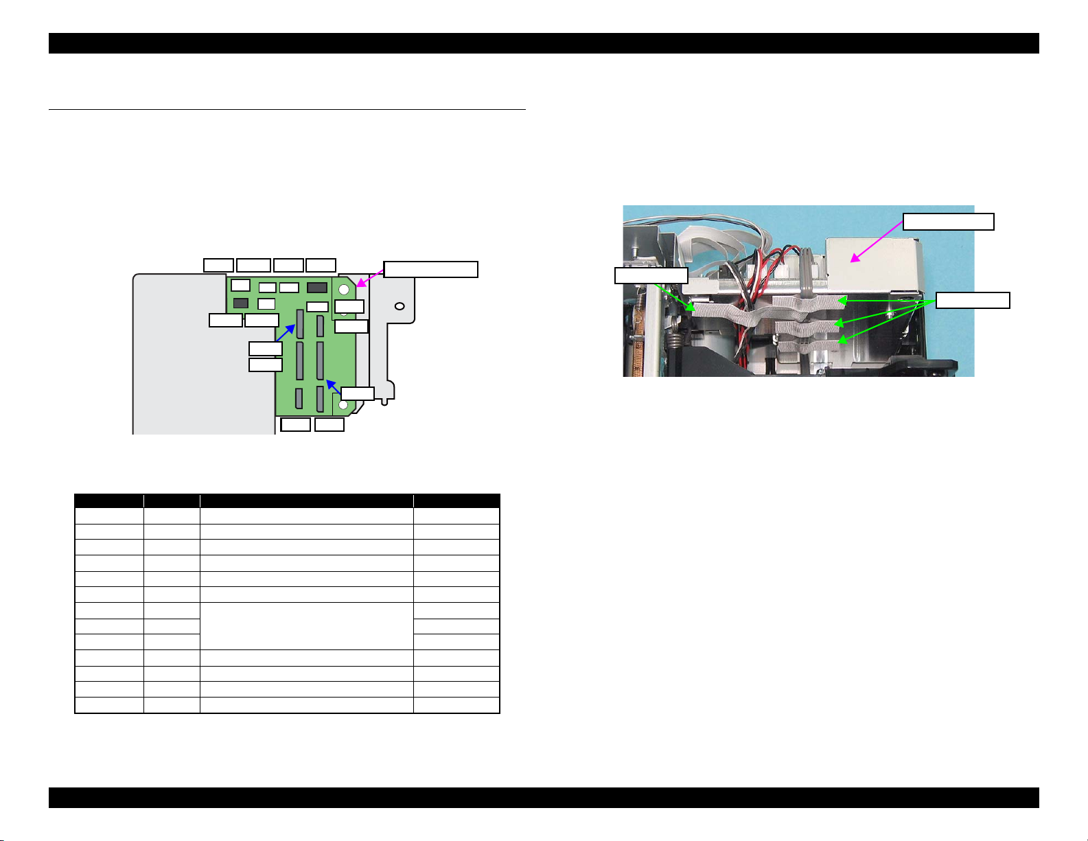
1.4.1 Main Board Unit
Removal procedure
Main Board Unit removal
1. Disconnect all connectors on the Main Board Unit.
2. Peel off the double-sided tape that secures the Panel FFC to the Holder Frame
and release the Panel FFC. (Fig.1-29 (p.30))
CN6 CN7CN3
CN17
CN4
CN13
CN14
CN12
CN11
CN16
CN10
CN5CN8
Figure 1-23. Connector layout of the Main Board
Table 1-3. List of Connectors and their Destinations
CN No.@ Color Destination Number of pins
CN3 White
CN4 White
CN5 FFC
CN6 White
CN7 Black
CN8 FFC
CN10 FFC
CN11 FFC 13pin
CN12 FFC 9pin
CN13 Black
CN14 White
CN16 FFC
CN17 White
P/S Assy
CDR Guide Sensor / CDR Tray Sensor
Panel Board
PE Sensor
APG Sensor
PF Encoder
Head FFC
PF Motor
CR Motor
PW Sensor / CR Encoder Sensor
Cover Open Sensor
Main Board Unit
3pin
4pin
8pin
3pin
3pin
5pin
13pin
2pin
2pin
6pin
2pin
3. Peel off the four acetate tapes that secures the following cables on the back of
the Main Board Unit.
•
Power Supply Cable
•
CR Motor Cable
•
PF Motor Cable
•
PE Motor Cable
•
APG Sensor Cable
Main Board Unit
Acetate Tape
Acetate Tape
Figure 1-24. Removing the Main Board Unit (1)
Disassembly/Reassembly Main Board Unit 27
Confidential
Page 28
L800/L801 Revision A
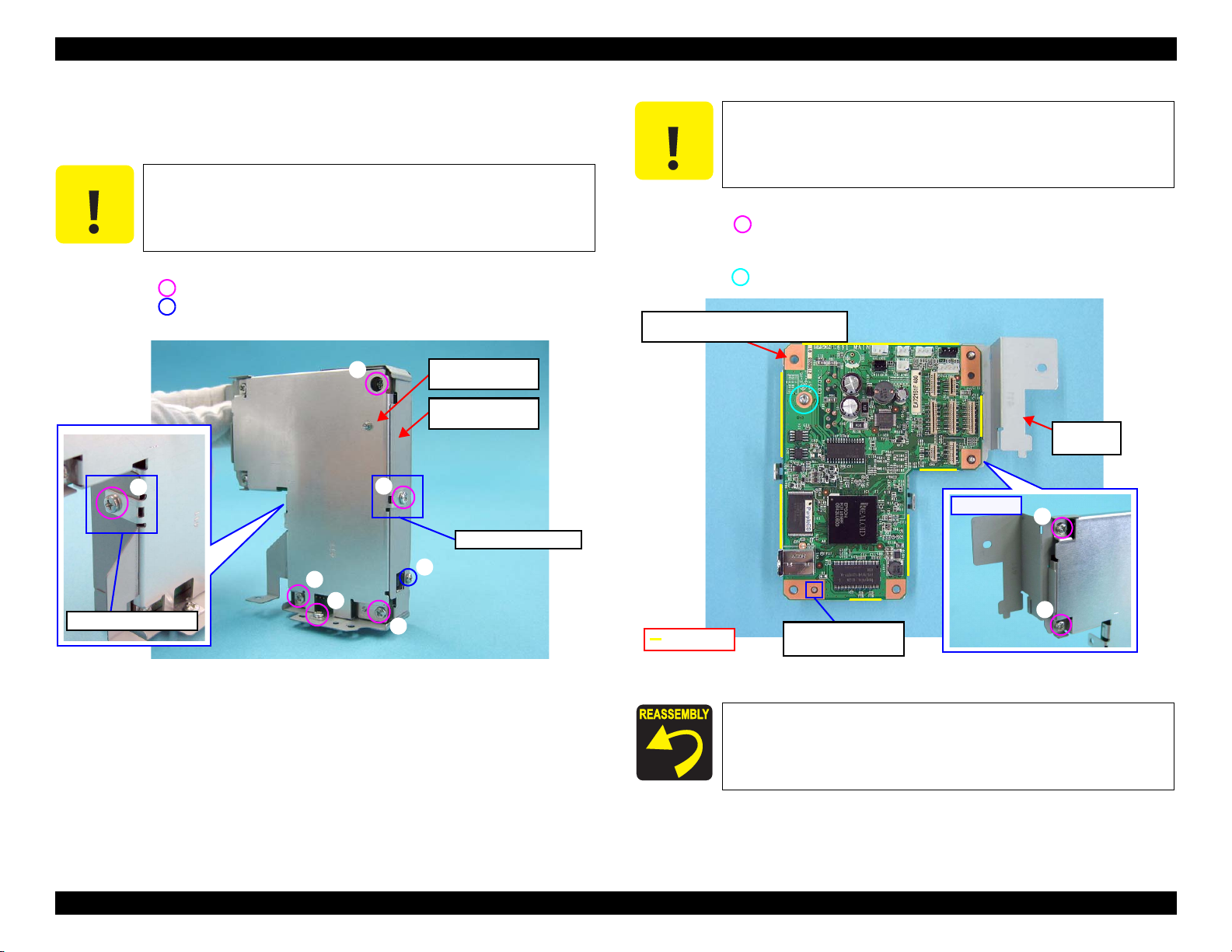
4. Remove the three screws and remove the Main Board Unit.
• Screw (2 pcs.): C.B.P.(P2) M3x8 (tightening torque: 5-7 kgf.cm)
• Screw (1 pc.): C.B.S. M3x6 (tightening torque: 7-9 kgf.cm)
(The numbers shown in the figure indicate the order of tightening the screws.)
[Upper Side]
[Left Side]
2
Positioning Holes
and Guide Pins
1
Main Board Unit
Figure 1-25. Removing the Main Board Unit (2)
After connecting the cables, secure them with acetate tape
following the procedures below.
1. Route the Power Supply Cable closely along the Lower Shield
Plate M/B, and secure the cable with acetate tapes at the
positions A, B, and C (30 mm each) as shown in Fig.1-26.
2. Avoiding the sharp edge shown in Fig.1-26, secure the
3
Rib
following cables with the acetate tape D (50 mm).
•
Power Supply Cable
•
CR Motor Cable
•
PF Motor Cable
•
PE Motor Cable
•
APG Sensor Cable
Positions of Acetate
tape A, B, C
A
B
Power Supply Cable
Main Board Unit
C
Lower Shield Plate
M/B
A D J U S T M E N T
R E Q U I R E D
Whenever the Main Board Unit is replaced, the required adjustment
must be carried out.
• Refer to "2.1.2 Required Adjustments" (p.74)
D
A
B
C
D
Sharp edge
When installing the Main Board Unit, be careful of the following:
Match the positioning holes with guide pins shown in Fig.1-25.
Insert the rib of the Main Board Unit into the positioning hole
of the Cable Holder Frame as shown in Fig.1-25.
Tighten the screws in the order given in Fig.1-25.
Edge of Lower
Shield Plate M/B
Figure 1-26. Routing the Cables
Align the upper left end
of acetate tape D with
the edge of the Lower
Shield Plate M/B.
Disassembly/Reassembly Main Board Unit 28
Confidential
Page 29
L800/L801 Revision A
Disassembling the Main Board Unit
1. Remove the Main Board Unit (p. 27).
C A U T I O N
Do not apply unnecessary force on the screw receiving parts of
the Lower Shield Plate M/B, as they are easy to deform.
When assembling or disassembling the Upper Shield Plate M/B,
be careful of its sharp edges.
2. Remove the seven screws and remove the Upper Shield Plate M/B.
• Screw (6 pcs.): C.B.S. M3x6 (tightening torque: 5-7 kgf.cm)
• Screw (1 pc.): C.P. M3x6 (tightening torque: 4-6 kgf.cm)
(The numbers shown in the figure indicate the order of tightening the screws.)
5
3
2
Lower Shield Plate
M/B
Upper Shield Plate
M/B
Screw Receiving Part
C A U T I O N
Be careful of the sharp edges shown in the figure below when
assembling or reassembling.
3. Remove the two screws and remove the Shield Plate M/B Sub.
• Screw (2 pcs.): C.B.S. M3x6 (tightening torque: 4-6 kgf.cm)
(The numbers shown in the figure indicate the order of tightening the screws.)
4. Remove the screw and remove the Main Board Unit.
• Screw C.B.S. M3x10 (tightening torque: 4-6 kgf.cm)
Upper Side: Main Board
Lower Side: Lower Shield Plate M/B
[Rear Side]
Shield Plate
M/B Sub
1
7
4
Screw Receiving Part
Figure 1-27. Removing the Upper Shield Plate M/B
1
2
6
Sharp edge
Positioning Hole and
Guide Pin
Figure 1-28. Removing the Main Board
When installing the Main Board, match the positioning hole
with the guide pin shown in Fig.1-28.
Tighten the screws in the order given in Fig.1-27 (p.29),
Fig.1-28.
Disassembly/Reassembly Main Board Unit 29
Confidential
Page 30
L800/L801 Revision A
1.4.2 Panel Assy/ Cover Open Sensor
Removal procedure
Panel Assy removal
1. Disconnect the Panel FFC from the connector (CN5) on the Main Board and
peel the Panel FFC off the Cable Holder Frame.
2. Disconnect the CDR Sensor Cable and Cover Open Sensor Cable from the
connectors (CN4, CN17) on the Main Board.
3. Release the CDR Sensor Cable and Cover Open Sensor Cable from the two
hooks of the Cable Holder Frame.
4. Peel off the acetate tape A, B to separate the CDR Sensor Cable from the
Cover Open Sensor Cable.
Hooks and Acetate Tape A, B
CN4CN17
Cover Open Sensor and
CDR Sensor Cable
C A U T I O N
When removing the screw (2) shown in Fig.1-30, be careful not to
damage the Cover Open Sensor Cable and CDR Sensor Cable.
5. Remove the two screws.
• Screw (3 pcs.): C.B.P. M3x6 (tightening torque: 5-7 kgf.cm)
• Screw (3 pcs.): C.B.P. M3x10 (tightening torque: 5-7 kgf.cm)
6. From the bottom of the Printer, insert a flathead screwdriver into the hole to
disengage the tab, and remove the Panel Assy.
Panel Assy
[Front side]
Open Sensor Holder
2
Tab
1
CN5
Main Board
Panel FFC
Figure 1-29. Removing the Panel Assy (1)
Cable Holder
Frame
Double sided Tape
Figure 1-30. Removing the Panel Assy (2)
Disengage
direction
Housing Lower
Disassembly/Reassembly Panel Assy/ Cover Open Sensor 30
Confidential
Page 31

L800/L801 Revision A
When Installing the Panel Assy, be careful of the following:
Tighten the screws in the order given in Fig.1-30.
When routing the FFCs and cables, follow the procedures
below referring to Fig.1-31.
1. Route the Panel FFC aligning its upper edge with the
reference line marked on the Cable Holder Frame, and
secure the FFC with double-sided tape.
2. Attach the acetate tape C along with the edge of the Cable
Holder Frame to secure the Panel FFC and Head FFC.
3. Tie the two cables together using two pieces of acetate tape
(20 mm each) so that the two tape positions come to the two
hooks of the Cable Holder Frame respectively. The cables
orientation must be as follows;
CDR cable: faces its black side upward
Cover Open Sensor cable: faces its gray side upward
4. Route the cables through the two hooks of the Cable Holder
Frame aligning the center of the tapes with the hooks.
Fold the Panel FFC along the
corner of the Upper Shield
Plate M/B.
Upper Side : CDR Sensor Cable
Panel FFC
Lower Side : Cover Open Sensor Cable
A
B
As shown in Fig.1-32, route the CDR Sensor Cable and Cover
Open Sensor Cable through the gap between the two ribs of
the Open Sensor Holder.
Cover Open Sensor Cable
CDR Sensor Cable
Ribs
Figure 1-32. Installing the Panel Assy (1)
As shown in Fig.1-30 (p.30) and Fig.1-33, match the
positioning holes of the Open Sensor Holder with the guide
pins of the Housing Lower, and secure the Open Sensor Holder
with the tab.
Open Sensor Holder
Do not route the
Panel FFC over
the screw of the
Cable Holder
Frame.
Figure 1-31. Routing the Cables
Hook
Ref. Line
Housing Lower
Positioning Hole
and Guide Pin
Figure 1-33. Installing the Panel Assy (2)
Disassembly/Reassembly Panel Assy/ Cover Open Sensor 31
Confidential
Page 32

L800/L801 Revision A
Panel Board / Buttons Removal
1. Remove the Panel Assy. (p.30)
2. Remove the two screws on the back of the Panel Assy, and remove the Panel
Cover.
• Screw : C.B.P. M3x10 (tightening torque: 3-5 kgf.cm)
3. Remove the screw on the front of the Panel Unit, and remove the Panel Unit
from the Open Sensor Holder by sliding it in the upper right direction.
• Screw : C.B.P. M3x10 (tightening torque: 3-5 kgf.cm)
[Front side]
Panel Cover
Panel Unit
[Back Side]
Hook of the Panel
Shield Plate
Open Sensor Holder
Figure 1-34. Removing the Panel Board / Buttons (1)
4. Disconnect the connector (CN1) on the Panel Board, peel the Panel FFC off
the back of the Panel Shield Plate, and remove the Panel FFC.
5. Remove the two screws and remove the Panel Shield Plate from the Panel
Unit.
• Screw : C.B.P. M3x10 (tightening torque: 3-5 kgf.cm)
Panel Unit[Front side]
Panel Shield Plate
[Back Side]
6. Disengage the hook on the back of the Panel Board and remove the Panel
Board.
[Back Side]
Positioning Hole
Hook
and Guide Pin
Panel Board
Figure 1-36. Removing the Panel Board / Buttons (3)
7. Release the three hooks and remove the PS button, the Ink button, and the
Paper button from the Housing Panel B.
8. Slide the Lens of the PS button, the Ink button, and the Paper button in the
direction of the arrow to remove it.
[Front side]
[Back Side]
Housing Panel B
Housing Panel B
Hook
CN1
Panel FFC
Reference Line
Double-sided Tape
PS Button
Ink Button
Paper Button
Lens
Step 8
Lens
Figure 1-35. Removing the Panel Board / Buttons (2)
Figure 1-37. Removing the Panel Board / Buttons (4)
Disassembly/Reassembly Panel Assy/ Cover Open Sensor 32
Confidential
Page 33

L800/L801 Revision A
When installing the Panel Unit, be careful of the following:
When installing the Panel Shield Plate to the Open Sensor
Holder, match the hook and guide pins with the positioning
holes shown in Fig.1-38 and insert the Panel Shield Plate into
the groove of the Open Sensor Holder to secure the Panel
Shield Plate.
[Upper Side]
Panel Shield Plate
Guide Pin and Positioning Hole
Open Sensor Holder
Hook and Positioning Hole
Groove
Figure 1-38. Installing the Panel Unit
Cover Open Sensor Removal
1. Remove the Panel Assy. (p.30)
2. From the back of the Open Sensor Holder, disengage the hook of the Cover
Open Sensor, and remove the Cover Open Sensor pulling its rib out of the
hole by rotating the sensor in the direction of the arrow.
3. Disconnect the connector from the Cover Open Sensor to remove the Cover
Open Sensor.
Cover Open Sensor
Connector
Hook
Rib
[Back Side]
Open Sensor Holder
Figure 1-39. Removing the Cover Open Sensor
When installing the Cover Open Sensor, insert the rib shown in
Fig.1-39 into the hole of the Open Sensor Holder, and secure the
Cover Open Sensor with the hook.
Attach the Panel FFC with double-sided tape along with the
reference line shown in Fig.1-35 (p.32).
When installing the Panel Board, match the guide pin with the
positioning hole shown in Fig.1-36.
Install the PS button, Ink button, and Paper button as shown
in Fig.1-37.
Disassembly/Reassembly Panel Assy/ Cover Open Sensor 33
Confidential
Page 34

L800/L801 Revision A
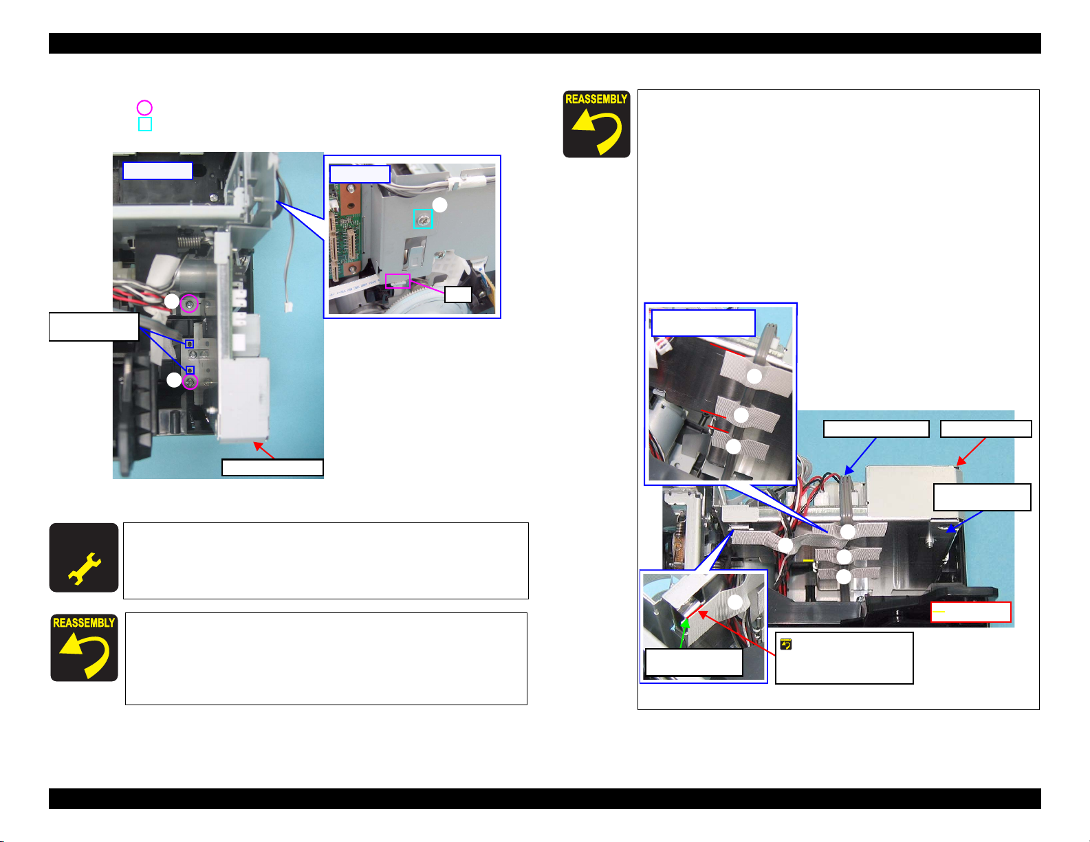
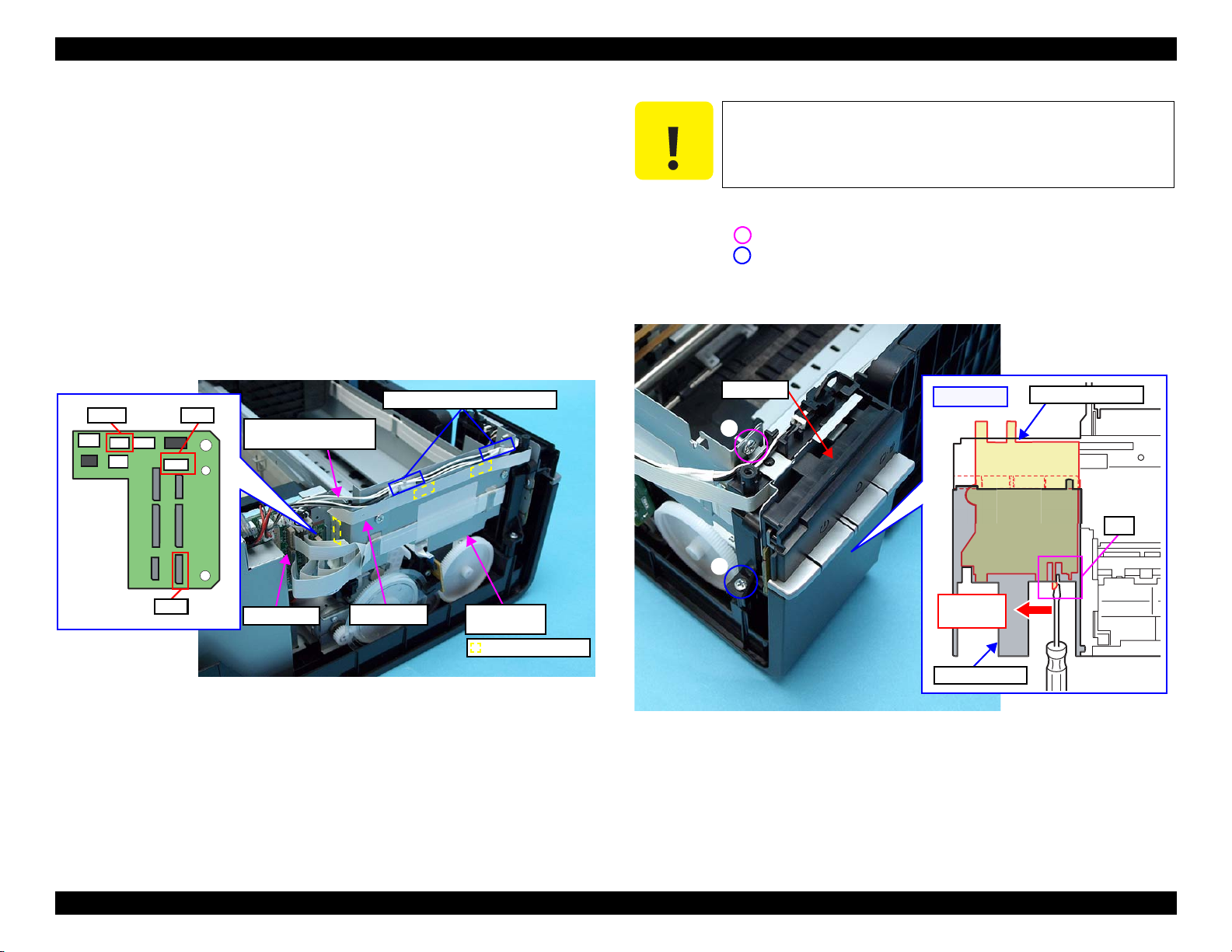
1.4.3 P/S Assy
Removal procedure
1. Peel off the acetate tape and remove the ferrite core from the groove of the
Housing Lower.
2. Remove the screw that secures the P/S Assy, and remove the P/S Assy from
the Housing Lower.
• Screw : C.B.P M3x10 (tightening torque: 5-7 kgf.cm)
Housing Lower P/S Assy
Acetate Tape
Figure 1-40. Removing the P/S Assy
When installing the P/S Assy, put the ferrite core into the groove of
the Housing Lower and secure it with acetate tape as shown in
Fig.1-40.
A D J U S T M E N T
R E Q U I R E D
Whenever the P/S Assy is replaced, the required adjustment must be
carried out.
• Refer to "2.1.2 Required Adjustments" (p.74)
Disassembly/Reassembly P/S Assy 34
Confidential
Page 35

L800/L801 Revision A
1.5 Disassembling the Printer Mechanism
C A U T I O N
1.5.1 Removing the Printer Mechanism
Removal procedure
Do not touch the PF Scale with bare hands or damage it.
If the Printer Mechanism is tilted leftward about 15°, the PF
Scale hits against the desk surface and can break. After
removing the Printer Mechanism, take extra care to protect
the PF Scale.
C A U T I O N
Be careful of the four sharp edges shown in the figure below
when assembling or reassembling.
Printer Mechanism Handling Precaution
When lifting the printer, hold parts shown in the figure
below to prevent the frame from deforming.
Sharp Edge
Figure 1-41. Printer Mechanism Handling Precaution (1)
Figure 1-42. Printer Mechanism Handling Precaution (2)
When removing the Waste Ink Tube, take care not to
contaminate the printer and surroundings with ink.
Extra care must be exercised not to scratch or damage the
Waste Ink Tube.
1. Pull out the Waste Ink Tube by hand.
m
s
i
n
a
h
c
e
M
r
e
t
n
i
r
P
Do not tilt more than 15
degrees, or drag it while tilting.
About
15°
Waste Ink Tube
Figure 1-43. Removing the Waste Ink Tube
Disassembly/Reassembly Removing the Printer Mechanism 35
Confidential
Page 36

L800/L801 Revision A
2. Release the Waste Ink Tube from the groove of the Waste Ink Tray.
3.
Release the CR Motor Cable from the two ribs of the Waste Ink Tray.
CR Motor Cable
Waste Ink Tube
Waste Ink Tube
Waste Ink Tray
Figure 1-44. Removing the Printer Mechanism (1)
4. Disconnect the connector of the CDR Guide Sensor.
CDR Guide Sensor
5. Remove the five screws and remove the Printer Mechanism.
Screw : C.B.P.(P2) M3x8 (tightening torque:5-7 kgf.cm)
(The numbers shown in the figure indicate the order of tightening the screws.)
5
2
1
4
3
Positioning Hole and
Guide Pin
Figure 1-46. Removing the Printer Mechanism (3)
CDR Guide Sensor Cable Opening
Figure 1-45. Removing the Printer Mechanism (2)
Disassembly/Reassembly Removing the Printer Mechanism 36
Confidential
Page 37

L800/L801 Revision A
When installing the Printer Mechanism, be careful of the
following:
Wipe off any ink on the joint portion of the Waste Ink Tube
before reconnecting the tube. Ink on the joint portion makes
the tube likely to get disconnected.
As shown in Fig.1-47, insert the Waste Ink Tube over the tube
of the Waste Ink Tray until the top end of the Waste Ink Tube
contacts with the rib.
Top end of Waste Ink Tube
Waste Ink Tray
Rib
Tube of Waste Ink Tray
Tube of Waste Ink Tray
Waste Ink Tube
Figure 1-47. Cautions of inserting the Waste Ink Tube
Match the positioning holes with guide pins (two pairs) shown
in Fig.1-46 (p.36).
Tighten the screws in the order given in Fig.1-46 (p.36).
Make sure the Waste Ink Tube or cables are not pinched
between the Printer Mechanism and the Housing Lower.
Route the CDR Guide Sensor Cable through the opening as
shown in Fig.1-45.
1.5.2 Printhead
C A U T I O N
Removal procedure
C H E C K
P O I N T
1. Move the CR Unit to the center, open the Cartridge Cover and remove all Ink
2. While disengaging the hook of the Head FFC Cover with a flathead
When removing the Head FFC Cover and the Head FFC
Cover Inner, do not use tools with sharp ends as the FFC may
get damaged.
Be careful not to damage the FFC and cables when
disengaging the hook of the Holder Contact.
See the section given below on how to unlock the carriage.
• “ 1.1.6 How to Unlock the Carriage ”
Cartridges.
screwdriver, slide the Head FFC Cover downward and remove it.
Head FFC Cover
Removal Direction
A D J U S T M E N T
R E Q U I R E D
Whenever the Printer Mechanism is replaced, the required
adjustments must be carried out.
• Refer to "2.1.2 Required Adjustments" (p.74)
Screwdriver
Hook
Figure 1-48. Removing the Head FFC Cover
Disassembly/Reassembly Printhead 37
Confidential
Page 38

L800/L801 Revision A
3. While disengaging the hook of the Head FFC Cover Inner with a flathead
screwdriver, slide the Head FFC Cover Inner upward and remove it.
Head FFC Cover Inner
Hook
Screwdriver
Removal Direction
Figure 1-49. Removing the Head FFC Cover Inner
4. Using the special tool (see p.15) disengage the hook A of the Holder Contact
on the left back of the Carriage Unit.
[Back Side]
Hook A
Holder Contact
Special Tool
5. Using the special tool (see p.15) disengage the hook B of the Holder Contact
on the right back of the Carriage Unit.
6. Slide the Holder Contact upward and remove the Holder Contact.
Removal Direction
[Back Side]
Holder Contact
Special Tool
Hook B
Figure 1-51. Removing the Holder Contact (2)
C A U T I O N
Take extra care not to spill ink and contaminate the surroundings.
Be extremely careful not to touch the nozzle surface, the ink supply
needles and the Head Cover, otherwise the nozzles may get
clogged.
Printhead
Head Cover
Nozzle surface
Figure 1-52. Handling of the Printhead
Figure 1-50. Removing the Holder Contact (1)
Disassembly/Reassembly Printhead 38
Confidential
Page 39

L800/L801 Revision A
7. Remove the three screws and remove the Printhead.
• Screw : C.B.P. M2.6x8 (tightening torque: 3-5 kgf.cm)
(The numbers shown in the figure indicate the order of tightening the screws.)
Tighten the screws in the order given in Fig.1-53.
3
2
Printhead
1
Figure 1-53. Removing the Printhead (1)
8. Remove the two Head FFCs from the connectors on the back, and remove the
Printhead.
Printhead
Head FFC
A D J U S T M E N T
R E Q U I R E D
Whenever the Printhead is removed/replaced, the required
adjustments must be carried out.
• Refer to "2.1.2 Required Adjustments" (p.74)
Connectors
Figure 1-54. Removing the Printhead (2)
Disassembly/Reassembly Printhead 39
Confidential
Page 40

L800/L801 Revision A
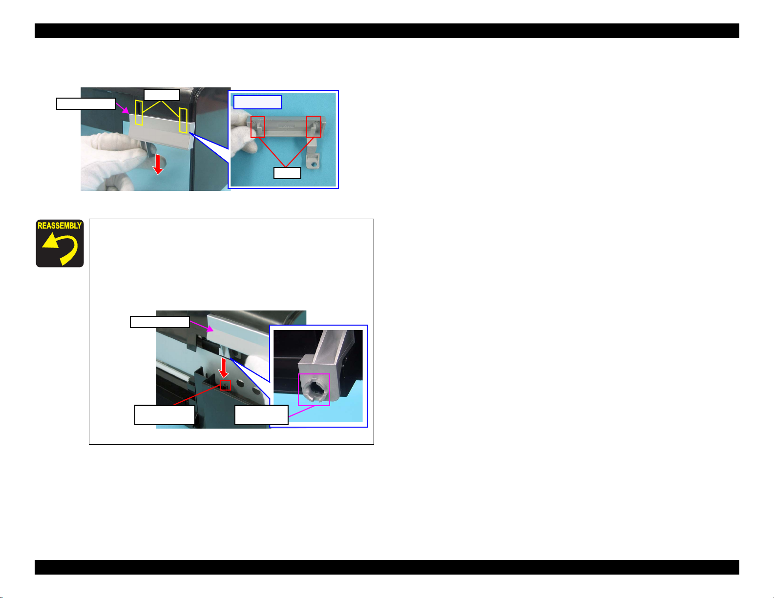
1.5.3 CR Scale
C A U T I O N
Removal procedure
C H E C K
P O I N T
1. Unlock the carriage and move the CR Unit to the center.
2. Remove the Torsion Spring from the hook ( ) on the left side of the Main
3. Remove the CR Scale from the hook ( ) on the right side of the Main
4. Pull out the CR Scale from the slit of the CR Unit.
5. Turn the CR Scale 90 degrees in the direction of the arrow, and remove the
During the disassembly/reassembly of the Printer Mechanism,
take extra care not to touch the CR Scale with bare hands, and not
to contaminate or scratch it.
See the section given below on how to unlock the carriage.
• “ 1.1.6 How to Unlock the Carriage ”
Frame.
Frame.
CR Scale from the hook.
Extension Spring
Install the CR Scale with its cut-corner facing upward. Hitch one end
of the Torsion Spring to the hole of the CR Scale from the back side of
the CR Scale.
Hitch from the back side
Cut-corner
Hook
Figure 1-56. Reinstalling the CR Scale
Slit
Hook
Turn 90°
CR Scale
Figure 1-55. Removing the CR Scale
Disassembly/Reassembly CR Scale 40
Confidential
Page 41

L800/L801 Revision A
1.5.4 APG Unit
Removal procedure
1. Remove the two screws taking care not to lose the gears, and remove the APG
Unit.
• Screw : C.B.S. M3x6 (tightening torque: 7-9 kgf.cm)
(The numbers shown in the figure indicate the order of tightening the screws.)
APG Unit
1
2
Figure 1-57. Removing the APG Unit
2. Remove the Combination Gear (10, 15.2).
Lubrication is required. See the page given below for the
lubrication information.
Lubrication of APG Unit (p.93)
Install the APG Unit following the procedure below.
1. Put a pin (thinner than Ø2mm) through the positioning
holes of the Main Frame and the right PG Cam on the CR
Shaft.
Positioning Hole
Pin (1)
Right PG Cam
Figure 1-59. Reinstalling the APG Unit (1)
2. Put the pin through the positioning holes of the Spur gear
28.8 and the APG Unit.
Front: Positioning Hole of Spur Gear 28.8
Back: Positioning Hole of APG Unit
Pin
Combination Gear (10,15.2)
Figure 1-58. Removing the Combination Gear (10, 15.2)
APG Unit
Spur Gear 28.8
Figure 1-60. Reinstalling the APG Unit (2)
Disassembly/Reassembly APG Unit 41
Confidential
Page 42

L800/L801 Revision A
3. Install the APG Unit to the Main Frame.
APG UnitPin
Figure 1-61. Reinstalling the APG Unit (3)
4. Check that the hooks ( ) are attached to the positioning
holes of the Main Frame, then screw the APG Unit.
Main Frame
1.5.5 Waste Ink Tray
Removal procedure
C A U T I O N
1. Remove the two screws, disengage the hook, and remove the Waste Ink Tray.
• Screw : C.B.P. M3x10 (tightening torque: 5-7 kgf.cm)
When removing the Waste Ink Tray, take extra care not to spill
ink and contaminate the printer and surroundings.
Waste Ink Tray
Hook
Figure 1-63. Removing the Waste Ink Tray
A D J U S T M E N T
R E Q U I R E D
Whenever the Waste Ink Tray is replaced, the required
adjustments must be carried out.
• Refer to "2.1.2 Required Adjustments" (p.74)
Figure 1-62. Reinstalling the APG Unit (4)
Tighten the screws in the order given in Fig.1-57 (p.41).
Disassembly/Reassembly Waste Ink Tray 42
Confidential
Page 43

L800/L801 Revision A
1.5.6 Waste Ink Pad Lower / Waste Ink Pad Cap Lower
Removal procedure
C A U T I O N
1. Remove the four Waste Ink Pad Lowers and Waste Ink Pad Cap Lower from
When removing the Waste Ink Pad Lower and Waste Ink Pad
Cap Lower, take extra care not to contaminate the printer and
surroundings with ink.
Be careful of the seven sharp edges shown in Fig.1-64 when
disassembling or reassembling.
the Housing Lower.
Waste Ink Pad Lower (x1)
Waste Ink Pad Cap Lower (x1)
Waste Ink Pad Lower (x3)
Figure 1-64. Removing the Waste Ink Pad
Insert the Waste Ink Pad Lowers into the Housing Lower inserting
the slits of the pads over the tabs on the Housing Lower. Make
sure to push the pads as far as they will go (until their top surface
locate lower than the top surface of the Housing Lower edges).
Sharp edge
A D J U S T M E N T
R E Q U I R E D
Whenever the Waste Ink Pad Lower is replaced, the required
adjustments must be carried out.
• Refer to "2.1.2 Required Adjustments" (p.74)
Tab
Slit
Figure 1-65. Installing the Waste Ink Pad Lower
Disassembly/Reassembly Waste Ink Pad Lower / Waste Ink Pad Cap Lower 43
Confidential
Page 44

L800/L801 Revision A
1.5.7 Left & Right Guide Stackers / CDR Guide Sensor
Removal procedure
C A U T I O N
Be careful of the seven sharp edges shown in
assembling or reassembling.
Left / Right Guide Stacker Removal
1. Remove the screw and remove the Left Guide Stacker.
• Screw : C.B.P. M3x8 (tightening torque: 5-7 kgf.cm)
2. Remove the screw and remove the Right Guide Stacker.
• Screw : C.B.P. M3x8 (tightening torque: 5-7 kgf.cm)
Left Guide Stacker
Left Guide Stacker
Fig.1-66
when
When installing the Left Guide Stacker, insert the rib indicated
with in
Fig.1-67
and match the positioning holes and guide
pins indicated with (two pairs).
When installing the Right Guide Stacker, match the
positioning holes and guide pins indicated with (two
pairs)
Left Guide
Stacker
in Fig.1-67
.
Right Guide
Stacker
Figure 1-67. Installing the Left / Right Guide Stacker
CDR Guide Sensor Removal
1. Disengage the two hooks on the back of the CDR Guide Sensor and remove
the CDR Guide Sensor.
Sharp edge
Right Guide Stacker
Figure 1-66. Removing the Left / Right Guide Stacker
Right Guide Stacker
CDR Guide Sensor
[Back Side]
Hooks
Figure 1-68. Removing the CDR Guide Sensor
Disassembly/Reassembly Left & Right Guide Stackers / CDR Guide Sensor 44
Confidential
Page 45

L800/L801 Revision A
1.5.8 Ink System
C A U T I O N
Removal procedure
C H E C K
P O I N T
Take extra care not to spill ink and contaminate the
surroundings. Also, when removing the Waste Ink Tube, be
careful not to spill the ink.
Extra care must be taken to avoid injury from sharp edges of
the rib of the Main Frame.
Be careful not to drop and damage the shaft of the Carriage
Lock and the Torsion Spring, as they easily come off.
Pump Section
Pump Section
See the section given below on how to unlock the carriage.
• “ 1.1.6 How to Unlock the Carriage ”
Torsion Spring
Shaft of the
Carriage Lock
Figure 1-69. Ink System
1. Move the CR Unit to the center.
2. Remove the screw (1) that secures the Cap section.
• Screw : C.B.S. M3x6 (tightening torque: 7-9 kgf.cm)
(The numbers shown in the figure indicate the order of tightening the screws.)
3. Insert a screwdriver through the hole of the Main Frame and remove the screw
(2) that secures the Pump section.
• Screw : C.B.S. M3x6 (tightening torque: 7-9 kgf.cm)
(The numbers shown in the figure indicate the order of tightening the screws.)
Hole
1
Cap section
2
Figure 1-70. Removing the Ink System (1)
4. Slide the Ink System to the direction of the arrow and disengage the Ink
System from the guide pin of the ASF Unit.
[Rear Side]
Guide Pin
Pump
Cap
Figure 1-71. Removing the Ink System (2)
Disassembly/Reassembly Ink System 45
Confidential
Page 46

L800/L801 Revision A
5. Remove the Ink System in the following procedures.
1.Slide it to the right.
2.Rotate it in the direction of the arrow (1) and release the pump part from
the Main Frame.
3.Pull it out toward you (arrow (2)).
Pump
1
2
Figure 1-72. Removing the Ink System (2)
When installing the Ink System, be careful of the following:
Lubrication is required. See the page given below for the
lubrication information.
Lubrication of Ink System (p.93)
Insert the shafts of the Ink System into the positioning holes
( ) of the Frame.
1.5.9 EJ Frame Assy
Removal procedure
1. Move the CR Unit to the home position side.
2. Remove the Tube Guide. (p. 67)
3. Peel off the acetate tape, and then release the Head FFC from the two hooks of
the Cable Holder Frame and pull out the Head FFC through the cutout.
4. Release the Head FFC from the three hooks of the Front Frame and peel off
the double-sided tape.
Acetate Tape
Cable Holder Frame
[Rear Side]
Double-sided TapeHead FFC
Front Frame
Hook
Acetate Tape Position
Cutout
Figure 1-74. Removing the Head FFC
Figure 1-73. Reinstalling the Ink System (1)
Tighten the screws in the order given in Fig.1-70.
After installing the Ink System, check the Carriage Lock for
proper operation referring to the section given below.
• “ 1.1.6 How to Unlock the Carriage ”
Insert the positioning hole of the Ink System shown in Fig.1-71
over the guide pin of the ASF Unit.
Disassembly/Reassembly EJ Frame Assy 46
Confidential
Page 47

L800/L801 Revision A
5. Disconnect the PF Encoder FFC from the PF Encoder.
6. Remove the two screws, disengage the two hooks of the Cable Holder Frame
from the Front Frame and Main Frame, and remove the Cable Holder Frame.
7. Screw : C.B.S. M3x6 (tightening torque: 7-9 kgf.cm)
(The numbers shown in the figure indicate the order of tightening the screws.)
[Back Side]
Cable Holder Frame
2
1
Hook
PF Encoder FFC
Figure 1-75. Removing the Cable Holder Frame
8. Peel off the PF Encoder FFC from the back of the Cable Holder Frame.
Cable Holder Frame
Cable Holder Frame
[Back Side]
9. Peel off the acetate tape to release the CDR Sensor Cable, and then remove
the screws on the right and left sides, and remove the Front Frame.
• Screw : C.B.S. M3x6 (tightening torque: 7-9 kgf.cm)
(The numbers shown in the figure indicate the order of tightening the screws.)
1
Front Frame
Acetate Tape
2
Positioning hole
and Guide Pin
Figure 1-77. Removing the Front Frame
10. Release the CDR Sensor Cable from the cable guide of the EJ Frame Assy.
11. Remove the EJ Frame Assy.
Removal Direction
Reference Line
Figure 1-76. Removing the PF Encoder FFC
PF Encoder FFC
EJ Frame Assy
CDR Sensor Cable
Cable Guide
Figure 1-78. Removing the EJ Frame Assy
Disassembly/Reassembly EJ Frame Assy 47
Confidential
Page 48

L800/L801 Revision A
When installing the EJ Frame Assy, be careful of the following:
Lubrication is required. See the page given below for the
lubrication information.
Lubrication of EJ Frame Assy (p.91)
As shown in Fig.1-79, insert the two bearings of the EJ Frame
Assy over the EJ Roller Shaft.
EJ Frame Assy
Bearing
EJ Roller Shaft
Bearing
Figure 1-79. Reinstalling the EJ Frame Assy
When installing the EJ Frame Assy, make sure that the Left/Right
EJ Frame Springs are attached as shown in
Fig.1-80
. Carefully
handle the EJ Frame Assy as the springs come off easily.
[Left Side]
Opposite
to HP
[Right Side]
HP Side
When installing the Front Frame, screw it after securing the foot
of the two EJ Frame Springs to the slits as shown in the figure.
Carefully handle the EJ Frame as the springs come off easily.
[Left Side]
Opposite
to HP
Left EJ Frame Spring
Right EJ Frame Spring
[Right Side]
HP Side
Figure 1-81. Reinstalling the Front Frame (2)
When installing the Cable Holder Frame, match the two hooks
of the Cable Holder Frame with the positioning holes of the
Main Frame and Front Frame as shown in Fig.1-75 (p.47), and
tighten the screws in the order given in the figure.
When installing the Cable Holder Frame, attach the PF
Encoder FFC along with the reference line shown in Fig.1-76
(p.47).
When installing the Front Frame, match the positioning holes
of the Front Frame with the guide pins of the Main Frame (two
pairs), and tighten the screws in the order given in Fig.1-77
(p.47).
Shorter
Left EJ Frame Spring
Right EJ Frame Spring
Figure 1-80. Reinstalling the Front Frame (1)
Longer
A D J U S T M E N T
R E Q U I R E D
Whenever the EJ Frame Assy is removed or replaced, the required
adjustments must be carried out.
• Refer to "2.1.2 Required Adjustments" (p.74)
Disassembly/Reassembly EJ Frame Assy 48
Confidential
Page 49

L800/L801 Revision A
1.5.10 PF Encoder / PF Scale
C A U T I O N
Removal procedure
1. Disconnect the FFC of the PF Encoder from CN1 connector.
2. Remove the screw and remove the PF Encoder.
• Screw : C.B.P. M2.6x8 (tightening torque: 3.5-4.5 kgf.cm)
3. Peel off the double-sided tape attached to the center part, and remove the PF
Take extra care not to contaminate or scratch the PF Scale. Never
touch the scale with bare hands.
Scale.
PF Scale Double-sided tape
FFC
Front Paper Guide
CN1
1.5.11 PF Motor
C A U T I O N
Removal procedure
1. Release the PF Motor Cable from the hook of the ASF Unit.
2. Remove the two screws that secure the PF Motor.
• Screw : C.P. M3x6 (tightening torque: 3-5 kgf.cm)
3. Slide the PF Motor to pull it out through the cutout and remove the PF Motor.
Be careful not to damage the Pinion Gear of the PF Motor.
(The numbers shown in the figure indicate the order of tightening the screws.)
PF Motor
PF Motor Cable
1
ASF Unit
Hook
2
PF Encoder
Figure 1-83. Removing the PF Motor
Figure 1-82. Removing the PF Encoder/PF Scale
A D J U S T M E N T
R E Q U I R E D
Whenever the PF Motor is replaced, the required adjustments
must be carried out.
• Refer to "2.1.2 Required Adjustments" (p.74)
When installing the PF Encoder, make sure the PF Encoder fits
firmly against the Front Paper Guide.
Disassembly/Reassembly PF Encoder / PF Scale 49
Confidential
Page 50

L800/L801 Revision A
1.5.12 CR Motor
Removal procedure
1. Remove the Extension Spring of the Driven Pulley Assy from the rear side.
[Rear Side]
Figure 1-84. Removing the Extension Spring
C A U T I O N
Take extra care not to contaminate the Timing Belt with grease.
The belt deteriorates faster if grease adheres to it.
2. Remove the Driven Pulley Assy and remove the Timing Belt from the Pinion
Gear of the CR Motor.
Driven Pulley Assy
Extension Spring
C A U T I O N
When assembling or disassembling the CR Motor, be careful of the
three sharp hooks of the Main Frame shown in Fig.1-86.
3. Release the connector cables from the three hooks, then peel off the three
acetate tapes to release the CR Motor cable.
[Rear Side]
CR Motor
CR Motor Cable
: Hook
Figure 1-86. Removing the CR Motor (2)
4. Insert a Phillips screwdriver (with a shaft of 13cm or longer is recommended)
through the hole of the Front Frame, remove the two screws, and remove the
CR Motor.
• Screw : C.P. M3x4 (tightening torque: 3-5 kgf.cm)
(The numbers shown in the figure indicate the order of tightening the screws.)
Driven Pulley Assy
1
CR Motor
Pinion GearTiming Belt
[Rear Side]
2
Figure 1-85. Removing the CR Motor (1)
Figure 1-87. Removing the CR Motor (3)
Disassembly/Reassembly CR Motor 50
Confidential
Page 51

L800/L801 Revision A
When routing the CR Motor Cable and PE Sensor Cable, refer
to Fig.1-88 and follow the steps below.
1. Wrap the CR Motor Cable with the acetate tape A (30 mm)
at the position of 100 mm away from the acetate tape that is
on the CR Motor side.
2. Tie the two cables together with the acetate tape B (20 mm)
at the position 60mm/40mm away from the acetate tape A/
PE Sensor connector.
3. Route the center of the acetate tape A behind the convex
portion of the Main Frame, and secure the tied cables with
the hook (1) at the center of the acetate tape B so that the
CR Motor Cable faces toward you.
4. Wrap the CR Motor Cable and PE Sensor Cable with
acetate tapes (20 mm) at the positions of the hooks (2) (3),
then secure the center of the acetate tapes with Hooks (2)
(3).
Convex
CR Motor
Portion of
Main
Frame
A
PE Sensor
2
3
A D J U S T M E N T
R E Q U I R E D
Lubrication is required. See the page given below for the
lubrication information.
Lubrication of Driven Pulley (p.90)
When installing the CR Motor, install it so that the print side
faces upwards.
Figure 1-89. Reinstalling the CR Motor
Whenever the CR Motor is replaced, the required adjustments
must be carried out.
• Refer to "2.1.2 Required Adjustments" (p.74)
B1
m
m
0
0
1
n
t
e
e
w
(
e
b
t
a
t
c
e
f
o
a
d
n
e
h
t
o
b
s
e
)
p
a
t
e
m
m
0
6
s
(
o
e
n
e
w
e
b
t
e
t
a
t
c
e
f
a
s
d
n
e
t
o
h
b
s
e
)
t
p
a
n
e
E
S
P
m
m
0
4
o
d
n
e
t
o
e
l
b
a
C
r
s
o
(
f
f
n
n
c
m
o
o
r
t
e
t
a
t
e
c
a
: Hook
r
o
t
e
c
)
e
p
a
Figure 1-88. Routing the Cable
Disassembly/Reassembly CR Motor 51
Confidential
Page 52

L800/L801 Revision A
1.5.13 CR Unit
Removal procedure
C A U T I O N
1.
2. Disengage the upper end of the Spring (1) from the slit, and remove the
3.
Before turning the Parallelism Bushing L, mark the scale position
of the Parallelism Bushing with a marker. And taking extra care
not to damage the Gear with the rib, pull it toward the front.
Remove the Cable Holder Frame.
(p.47)
Spring (1).
Loosen the screw ( ), and turn the Parallelism Bushing L clockwise to the
maximum.
[Left Side]
Spring (1)
Slit
4. Disengage the end of the Spring (2) from the hook, and the other end from the
slit of the CR shaft, and remove the Spring (2).
5. Remove the washer by expanding the gap between the washer and the Right
PG Cam using a pair of Tweezers, and remove the Right PG Cam.
CR Shaft
Washer
Removal Direction
Spring (2)
Right PG Cam
[Right Side]
Hook
Figure 1-91. Removing the CR unit (2)
C A U T I O N
When removing the CR Unit in the next step, be careful not to
damage the CR Shaft by bumping it against the pinion gear of the
CR Motor.
Parallelism Bushing L
6. Hold the CR Unit from the bottom and lift up the CR Shaft, release from the
bushing in the (1) (2) order, and remove the CR Unit with the Shaft from the
Main Frame.
CR Unit
Figure 1-90. Removing the CR Unit (1)
1
CR Shaft
2
Bushing
Bushing
Figure 1-92. Removing the CR Unit (3)
Disassembly/Reassembly CR Unit 52
Confidential
Page 53

L800/L801 Revision A
7. Remove the CR Shaft from the CR Unit.
CR Shaft
CR Unit
Figure 1-93. Removing the CR Unit (4)
8. Remove the Timing Belt from the CR Unit.
CR Unit
CR Unit
Timing Belt
Figure 1-94. Removing the CR Unit (5)
9. Disconnect the FFC from the CR Encoder connector, pull out the FFC from
the slit of the CR Unit, and remove the Head FFC.
Lubrication is required. See the page given below for the
lubrication information.
Lubrication of CR Unit (p.92)
Before attaching the right PG cam, remove the APG Unit and
install the cam matching its phase with the APG Unit.
(Refer to Reinstalling the APG Unit (p.41))
When attaching the spring (2) and the washer for the Right PG
Cam to the CR Shaft, make sure to attach them to the
positioning slits on the CR Shaft. (See Fig.1-91 (p.52))
When installing the Timing Belt, make sure that it is not
twisted and the lumpy side comes to the inner side.
Up
Lumpy side
(Inner side)
Flat side
(Outer side)
Lumpy on both inner/
outer side
Figure 1-96. Reinstalling the Timing Belt
When installing the CR Unit, hook the Guide part to the Main
Frame.
CR Unit
Head FFC
CR Unit
Guide Part
Figure 1-97. Reinstalling the CR Unit
A D J U S T M E N T
R E Q U I R E D
Figure 1-95. Removing the CR Unit (6)
Whenever the CR Unit is removed or replaced, the required
adjustments must be carried out.
• Refer to "2.1.2 Required Adjustments" (p.74)
Disassembly/Reassembly CR Unit 53
Confidential
Page 54

L800/L801 Revision A
1.5.14 ASF Unit
Removal procedure
Removing the LD Roller Guide
1. Move the CR Unit to the left (the opposite side to the home position).
2. Remove the screw that secures the LD Roller Guide.
• Screw : C.B.S. (P4), M3x6 (tightening torque: 7-9 kgf.cm)
C A U T I O N
3. Push the tabs on the right and the left, slide the LD Roller Guide upward to
When performing the following steps, be careful not to damage the
hooks of the LD Roller Guide.
remove it disengaging the five hooks.
HookTab
Hook
Removal Direction
4. Remove the Torsion Spring 137.7 from the LD Roller Guide.
Torsion Spring
LD Roller Guide
Figure 1-99. Removing the LD Roller Guide (2)
Removing the ASF Unit
1. Release the following cables from the ASF Unit.
• CR Motor Cable
• PF Motor Cable
• PE Motor Cable
ASF Unit
Hook
Figure 1-100. Releasing the Cables
LD Roller Guide
2. Remove the two screws on the rear side.
• Screw : C.B.S.(P4), M3x6
(tightening torque: (1) 7-9 kgf.cm, (2) 9-11 kgf.cm)
(The numbers shown in the figure indicate the order of tightening the screws.
[Rear Side]
1
2
Figure 1-98. Removing the LD Roller Guide (1)
ASF Unit
Figure 1-101. Disengaging the Hooks (ASF Unit)
Disassembly/Reassembly ASF Unit 54
Confidential
)
Page 55

L800/L801 Revision A
3. Disengage the two hooks (1) (2) that secure the ASF Unit from the Main
Frame.
4. Remove the Combination Gear (10,15.2), then remove the ASF Unit while
releasing the edge of the Change Lever from the hole of the Main Frame.
Hook (1)
Change Lever
Hook (2)
[Rear Side]
Lubrication is required. See the page given below for the
lubrication information.
Lubrication of ASF Unit (p.94)
When installing the ASF Unit, make sure that the Combination
Gear, tip of the Change Lever and the two hooks are securely
attached. Also make sure that there is appropriate space at
both the left and right of the Change Lever.
Tighten the screws in the order given in Fig.1-101 (p.54).
Install the LD Roller following the procedure below. Make
sure to apply grease referring to the page given below.
Lubrication of the ASF Unit (p.94)
1. Install the LD Roller aligning the arrow on the LD Roller with
the arrow on the blade of the shaft. Make sure the LD Roller is
securely attached without gap or misalignment.
LD Roller
Align the arrows
ASF Unit
LD Roller Shaft
Combination
Gear
Removal Direction
ASF Unit
A D J U S T M E N T
R E Q U I R E D
Blade
Figure 1-103. Reinstalling the LD Roller
Whenever the ASF Unit is removed or replaced, the required
adjustments must be carried out.
• Refer to "2.1.2 Required Adjustments" (p.74)
Figure 1-102. Removing the ASF Unit
Disassembly/Reassembly ASF Unit 55
Confidential
Page 56

L800/L801 Revision A
1.5.15 Upper Paper Guide
C A U T I O N
Removal procedure
1. Remove the three springs from the rear side, disengage the three hooks and
2.
Upper Paper Guide
Be sure to follow the procedure below to remove the Upper
Paper Guide to avoid damaging the PE Sensor Lever.
It is recommended to place a transparent sheet between the
Upper and Front Paper Guides to avoid scratching the roller.
Do not touch the roller surface with bare hands as it can
adversely affect the print quality.
remove the Upper Paper Guide from the Main Frame.
Spring
Hook
[Rear Side]
Figure 1-104. Removing the Upper Paper Guide (1)
Remove the Upper paper Guide pressing part to lower the tip of the PE
Sensor Lever.
Tip
C H E C K
P O I N T
A D J U S T M E N T
R E Q U I R E D
The figure below is the Upper Paper Guide. The two thin shafts
indicated with the arrows are likely to break, however, the Upper
Paper Guide does not need to be replaced even if the shafts become
broken. Because the shafts do not go on the bushings of the Printer
Frame.
Do not touch with bare hands.
When installing the three springs, secure the ends of the springs on
the hooks of the Main Frame as shown in Fig.1-106.
Main Frame
Spring
Hook
Figure 1-106. Installing the Springs
Whenever the Front Paper Guide Assy is removed or replaced, the
required adjustments must be carried out.
• Refer to "2.1.2 Required Adjustments" (p.74)
Press
Removal Direction
PE Sensor Lever
Figure 1-105. Removing the Upper Paper Guide
Disassembly/Reassembly Upper Paper Guide 56
Confidential
Page 57

L800/L801 Revision A
1.5.16 APG Sensor Assy
Removal procedure
1. Disengage the two hooks and remove the APG Sensor Assy.
APG Sensor Assy
Figure 1-107. Removing the APG Sensor
:Hook
1.5.17 Front Paper Guide Assy
C A U T I O N
Removal procedure
1. Remove the screw and remove the Parallelism Bushing L.
• Screw : C.B.S.(P2) M3x8 (tightening torque: 6-8 kgf.cm)
[Rear Side]
Do not touch the surface of the rubber roller of the EJ Roller Assy
and the coated part of the PF Roller Assy as it can adversely affect
the print quality.
Parallelism Bushing L
Front Paper Guide Assy
Positioning Hole and Guide Pin
Figure 1-108. Removing the Parallelism Bushing L
Disassembly/Reassembly APG Sensor Assy 57
Confidential
Page 58

L800/L801 Revision A
2. Disconnect the connector of the PE Sensor Cable on the rear side of the
printer.
3. Remove the screw that secures the Front Paper Guide Assy.
• Screw : C.B.S. M3x6 (tightening torque: 7-9 kgf.cm)
Connector
PE Sensor Cable
Front Paper Guide Assy
Figure 1-109. Removing the PE Sensor Cable
4. Pull out the EJ Ground Spring to the front side.
Front Paper Guide Assy EJ Ground Spring
5. Remove the Front Paper Guide Assy, following the steps below.
(1) Lift part to disengage the left side of the Front Paper Guide Assy.
(2) Slide the assy leftward little by little to disengage the right side of the assy.
(3) Remove the Front Paper Guide Assy while releasing its shaft from the cutout
of the rib on the left side of the Main Frame.
2
Cutout
Front Paper Guide Assy
1
Removal Direction
2
Figure 1-111. Removing the Front Paper Guide Assy
Lubrication is required. See the page given below for the
lubrication information.
Lubrication of Front Paper Guide Assy (p.91)
Figure 1-110. Removing the EJ Ground Spring
Disassembly/Reassembly Front Paper Guide Assy 58
Confidential
Page 59

L800/L801 Revision A
When installing the Front Paper Guide Assy, pull out the CDR
Tray Sensor cable as shown below.
Place the four tips of the Front Paper Guide Pad on the Waste
Ink Pad.
CDR Tray Sensor Cable
[Left Front Bottom Side]
Pull out the cable
from here
Figure 1-112. Routing the CDR Tray Sensor Cable
Attach the long foot of the EJ Ground Spring as follows; (1)
put it through the gap under the portion contacts with the EJ
Roller, (2) let it contact with the Main Frame, (3) let it contact
with the PF Roller shaft, (4) put it through the hole on the
frame. When finished, make sure the spring properly contacts
with (1), (2), (3), and (4) points.
Contacts with PF Roller Shaft
Contacts with EJ Roller shaft
Contacts with Main Frame
Long foot of EJ Ground Spring
4
3
1
2
A D J U S T M E N T
R E Q U I R E D
[Bottom Side]
Tip of Front Paper
Guide Pad
Waste Ink Pad Position
Tip
Tip
Figure 1-114. Installing Front Paper Guide Pad
When installing Parallelism Bushing L, match the positioning
hole with the guide pin shown in Fig.1-108 (p.57).
Whenever the Front Paper Guide Assy is removed or replaced, the
required adjustments must be carried out.
• Refer to "2.1.2 Required Adjustments" (p.74)
1
Hole
4
Gap
Figure 1-113. Attaching the EJ Ground Spring
Be careful not to deform the EJ Ground Spring.
Disassembly/Reassembly Front Paper Guide Assy 59
Confidential
Page 60

L800/L801 Revision A
1.5.18 CDR Tray Sensor
Removal procedure
C A U T I O N
1. Disengage the hook of the CDR Tray Sensor.
2. Turn the CDR Tray Sensor 90 degrees in the direction of the arrow to
Always follow the steps below to remove the CDR Tray Sensor, or
one of its hooks can be broken.
disengage its another hook, and pull it out from the hole to remove it together
with the CDR Guide Sensor.
CDR Tray Sensor
Hook
90-degrees Turn
Figure 1-115. Removing the CDR Tray Sensor
Disassembly/Reassembly CDR Tray Sensor 60
Confidential
Page 61

L800/L801 Revision A
1.6 Disassembling the CISS section
1.6.1 Refilling Ink Label / Valve Position Label
Refilling Ink Label
67 mm
103 mm
Valve Position Label
7.5 mm
7.5 mm
1.6.2 Top Cover
Marking
When attaching the Top Cover Label, align it with the markings on the Top Cover as
shown in the figure above.
Marking
6.4 mm
Attach the Refilling Ink Label and Valve Position Label according to the standards
shown in the figure above.
Disassembly/Reassembly Refilling Ink Label / Valve Position Label 61
Confidential
Page 62

L800/L801 Revision A
1.6.3 Tube Valve Holder Front / Rear 1.6.4 Valve Lever
Ink Supply Tank Tube
Tube Valve Holder Front
3
1 2
Tube Valve
Holder Rear
Ink Supply
Tank Tube
CBP. 3X6 (3-5kgf.cm)
Valve Case
Back side
Valve Case
Ink Supply Tank
Positioning Hole Dowel
Tube Valve Holder Rear
Tube Valve Holder Rear
Tube Valve
Holder Front
Hook
Rib
Ink Supply Tank Assy
Valve Lever
Tube Valve Holder Rear
Flathead precision
screwdriver
Right Cover
Hook
When routing the Ink Supply Tank Tubes, align them with their red lines facing the Tube
Valve Holder Front without any twist.
Follow the procedure below when installing the Tube Valve Holder Rear.
1. Insert the ribs (x2) of the Tube Valve Holder Rear under the hooks (x2) of the Valve
Case.
Follow the procedure below when removing the Valve Lever.
1. Remove the Ink Supply Tank Assy from the printer.
2. Insert a flathead precision screwdriver or the like into the gap between the Right
Cover and the Tube Valve Holder Rear to release the hook of the Valve Lever, and
then remove the Valve Lever.
2. Align the dowels (x4) of the Tube Valve Holder Rear with the positioning holes (x2)
of the Ink Supply Tank and the positioning holes (x2) of the Tube Valve Holder Front.
3. Make sure no Ink Supply Tank Tubes are caught, then secure it with the screws (x3) in
the order shown in the above figure.
Disassembly/Reassembly Tube Valve Holder Front / Rear 62
Confidential
Page 63

L800/L801 Revision A
1.6.5 Bottom Cover / Left Cover / Right Cover / Cover Joint
Left Cover
Bottom Cover
2 3 4 5 6 7
1
Cover Joint
Ink Supply Tank Assy
Right Cover
8
C.B.P. 3X6 (3-5kgf.cm)
Hook
Rib
Be careful about how to place the Ink Supply Tank Assy in order to prevent printing failure from occurring. (See “How to place the Ink Tank Assy when disassembling/reassembling” (p.10).)
The figures above indicate the hooks and ribs that secure the parts.
Remove the exterior parts of the Ink Supply Tank Assy in the following order.
1. Remove the screws (x8) of the Bottom Cover, and remove the Bottom Cover.
2. Remove the Left Cover and Right Cover.
3. Remove the Cover Joint.
Tighten the screws in the order indicated in the figure above.
Disassembly/Reassembly Bottom Cover / Left Cover / Right Cover / Cover Joint 63
Confidential
Page 64

L800/L801 Revision A
1.6.6 Ink Supply Tank Assy 1.6.7 Ink Supply Tank Tube Assy
Valve Case Tube Clamp Joint
Ink Supply Tank
Film
Be careful not to damage or peel off the film of the Ink Supply Tank.
Be careful about how to place the Ink Supply Tank Assy in order to prevent printing
failure from occurring. (See “How to place the Ink Tank Assy when disassembling/
reassembling” (p.10).)
120 ± 1 mm
211 ± 1 mm
Ink Supply
Tank Tube
0.5 mm or less
Ink Supply Tank
Yellow
Black
Light Cyan 333 ± 3 mm
Light Magenta 310 ± 3 mm
Magenta
Cyan
Ink Supply Tank Tubes
388 ± 4 mm
359 ± 4 mm
280 ± 3 mm
258 ± 3 mm
Valve Case
CMLMLCBkY
Route the Ink Supply Tank Tubes with the red lines facing upward (as viewed when
the Ink Supply Tank Assy is installed on the printer) and connect them to the Ink
Supply Tank Assy without any twist.
When connecting the Ink Supply Tank Tubes to the Ink Supply Tank, confirm the
color indicated on the film of the Ink Supply Tank, and take care not to connect them
with wrong joints.
When connecting the Ink Supply Tank Tubes to the Ink Supply Tank, insert the tubes
to the full and make sure the gaps between the end of tubes and the tank are 0.5 mm
long or less.
Disassembly/Reassembly Ink Supply Tank Assy 64
Confidential
Page 65

L800/L801 Revision A
1.6.8 Joint 1.6.9 Cover Case
Adapter Side
Joint
Front
Tank Side
Joint
Cover Case
Rib
Ink Supply Tube
Back
Adapter Side
Ink Supply Tube
0.5 mm or less
Joint
Tank Side
Joint
0.5 mm or less
Joint
Ink Supply Tank Tube
Cutout
Front Frame
1
The location where Front Frame may interfere.
Cover Case
Front Frame
The location where Front Frame may interfere.
C.B.P. 3X8 (5-7kgf.cm)
Dowel
Section B
Section A
Be careful not to damage the Cover Case with the edges of the front frame.
2
1
Cover Case
Section C
Cover Case
Follow the procedure below when removing the Cover Case.
1. Remove the screw (x1).
Make sure the red lines of the Ink Supply Tank Tube and Ink Supply Tube facing
upward.
When attaching the Joint, align the cutout of the Joint with the rib of the Cover Case.
Make sure the gaps between the end of Ink Supply Tank Tubes or Ink Supply Tubes
and the Joint are 0.5 mm long or less.
2. Lift the Cover Case slightly to release the dowels (x2) on the bottom of the Cover
Case.
3. Rotate the Cover Case in the direction of the arrow (1) to avoid the section A and B of
the Cover Case from bumping against the Front Frame.
4. Remove the Cover Case in the direction of the arrow (2) while avoiding the section C
of the Cover Case from bumping against the Front Frame.
Disassembly/Reassembly Joint 65
Confidential
Page 66

L800/L801 Revision A
1.6.10 PF Scale Cover / PF Scale Sheet 1.6.11 Tube Guide Sheet / Tube Guide Sheet Sub
PF Scale Sheet
PF Scale Cover
CBP. 3X8 (5-7kgf.cm)
PF Scale Cover PF Scale Sheet
Double-sided
tape
attachment
position
Main Frame
Wiping Area
Groove
Double-sided tape
attachment position
Front Paper Guide Assy
Tube Guide Sheet
Cross Section
OK
NG
Hole 1
Hole 1
Section A
Tube Guide Sheet
Hole 2
Hole 2
Tube Guide Sheet Sub
Tube Guide Sheet Sub
Tube Guide Sheet
Tube Guide
Tube Guide Sheet
Section A
Follow the procedure below when attaching the PF Scale Cover/PF Scale Sheet.
1. Wipe off the area on the Main Frame shown above using a cloth moistened with
alcohol.
2. Align the PF Scale Cover with the rib of the Front Paper Guide Assy, and attach the
PF Scale Cover.
3. Align the screw holes of the PF Scale Cover and Front Paper Guide Assy, and secure
the PF Scale Cover with the screw (x1).
4. After the alcohol dried out completely, insert the section A of the PF Scale Sheet into
the groove of the Front Paper Guide Assy, and then attach it with double-sided tape.
Rib
Refer the figure above and follow the procedure below when attaching the Tube
Guide Sheet Sub to the Tube Guide Sheet.
1. Insert the section A of the Tube Guide Sheet Sub into the hole 1 of the Tube Guide
Sheet from the bottom.
2. Insert the section A of the Tube Guide Sheet Sub into the hole 2 of the Tube Guide
Sheet from the top.
When attaching the Tube Guide Sheet to the Tube Guide, while keeping the Tube
Guide Sheet Sub attached on the Tube Guide Sheet, align the holes of the Tube Guide
Sheet with the protrusions of the Tube Guide.
Disassembly/Reassembly PF Scale Cover / PF Scale Sheet 66
Confidential
Page 67

L800/L801 Revision A
1.6.12 Ink Supply Tube Assy
Ink Supply Tube Assy
Adapter Assy side
Yellow
Black
Light Cyan
Light Magenta
Magenta
Cyan
Step5
Tube Porous Pad
Ink Supply Tube
90 mm 70 mm 75 mm 55 mm
Markings
Tube Clamps
Markings (on the back)
Ink Supply Tube
70 mm
Step7
Ink Supply Tube
Tube Clamps
Adapter
Joint side
CR Unit
Grooves
Align markings with
edge of grooves.
Step1-2,4
CR Unit
Step3
OK
Section A Hole
Tube Guide
Sheet Sub
Ink Supply
Tube
Ink Supply Tube
1
NG
3
2
Joint
Tube Holders
CBP. 3X8 (5-7kgf.cm)
Section A Hole
Tube Guide
Sheet Sub
Ink Supply
Tube
Make sure the Tube Clamps (with Porous Pad Tube attached) (x3) are attached on the positions on the Ink Supply Tube shown above.
Follow the procedure below when installing the Ink Supply Tube Assy.
1. Place the Ink Supply Tube onto the Tube Guide Sheet with its Tube Porous Pad side down.
2. Connect the Ink Supply Tubes (x6) to the Joint.
3. Insert the section A of the Tube Guide Sheet Sub from the top into the hole of the Tube Guide Sheet Sub to secure it.
4. Attach the Tube Holders (x3) and secure them with the screws in the order shown in the figure above.
5. Hold the Ink Supply Tube by the Adapter side and flip it over as shown in the figure, then put a marking on the bottom side of the Ink Supply Tube 70 mm from the Tube Clamp nearest to the Adapter.
6. Connect the Ink Supply Tube to the Adapter, and install the Adapter to the CR Unit. (p.68)
7. Route the Ink Supply Tubes through the grooves of the CR Unit, and align the markings on the Ink Supply Tubes with the edge of the grooves as shown in the figure above.
Disassembly/Reassembly Ink Supply Tube Assy 67
Confidential
Page 68

L800/L801 Revision A
1.6.13 Adapter Cover 1.6.14 Adapter
Tube Guide Sheet
Timing Belt
Ink Supply Tube Assy
Dowel
Hook
Adapter Cover
CR Unit
Adapter Cover
Hole
CBP. 3X8 (5-7kgf.cm)
Adapter
Hook
Adapter
Film
Connection of Ink Supply Tubes
Ink Supply Tube
Hook
Follow the procedure below when installing the Adapter Cover to the CR Unit.
1. Attach the Tube Guide Sheet to the Adapter Cover.
2. Insert the dowels (x2) of the Adapter Cover into the holes (x2) of the CR Unit and
engage the hook of the Adapter Cover to the CR Unit.
3. Make sure no Ink Supply Tubes are caught, then secure the Adapter Cover with the
screw (x1).
After installing the Adapter Cover to the CR Unit, move the CR Unit from side to
Be careful not to damage or peel off the film of the Adapter.
Use a precision screwdriver when releasing the hooks of the Adapter.
When connecting the Ink Supply Tubes to the Adapter, make sure the red lines on the Ink
Supply Tubes are facing upward as shown in the figure above.
side while holding the Timing Belt to make sure that the Ink Supply Tube Assy does
not apply extra load of the CR Unit movement.
Disassembly/Reassembly Adapter Cover 68
Confidential
Page 69

ADJUSTMENT
CHAPTER
2
Confidential
Page 70

L800/L801 Revision A
2.1 Adjustment Items and Overview
This chapter describes adjustments necessary after the disassembly/reassembly
of the printer.
2.1.1 Servicing Adjustment Item List
The adjustment items of this product are as follows.
Table 2-1. Adjustment Items
Adjustment Item
PG adjustment
EEPROM data copy
Initial setting
Head ID input
Initialize PF deterioration
offset
Disenable PF deterioration
offset
TOP margin adjustment
Install the Head Nozzle surface parallel to the printing surface and set
the gap between the paper and the Head Nozzle surface to the specified
value.
When the main board needs to be replaced, use this to copy adjustment
values stored on the old main board to the new board. If this copy is
completed successfully, all the other adjustments required after
replacing the main board are no longer be necessary.
This must be carried out after replacing the main board to apply
settings for the target market. When this function is performed, the
upper limit value of the ink tube counter is automatically set. With this
function, the serial number written on the main board can be checked,
and also writing the serial number to the main board can be performed
when replacing the board.
This must be carried out after replacing the printhead in order to enter
the new printhead ID (Head ID) that reduces variation between
printheads.
Resets the counter to maintain paper feed accuracy which decreases
due to paper dust.
When reading the counter value from the old main board is impossible
in the case of replacing the board, use this to set the counter to its
maximum value.
This corrects top margin of printout. A top margin adjustment pattern is printed. Examine the lines printed
Purpose Method Outline Tool
C H E C K
P O I N T
For information on how to carry out the adjustments and
media required for the adjustments, see the instructions
displayed by the Adjustment Program.
Some pictures in this manual are for Epson Stylus Photo R280/
R285/R290; therefore, the shapes of the parts are different
from those of L800/L801, but the differences does not affect the
adjustment procedures.
Mechanical adjustment using the thickness gauges. Make a proper
adjustment according to the result whether the manually-moved
carriage (printhead) runs over or hits against the gauges placed on the
platen.
Readout the EEPROM data from the main board before removing it.
Then replace the board with a new one, and load the EEPROM data to
the new board.
Select the target market. The selected market settings are automatically
written to the main board.
When writing the serial number, enter and re-enter (for confirmation)
the printer serial number, then press the input button.
Enter the ID printed on the Head QR code label attached on the
printhead. The correction values are automatically written to the main
board.
Reset the counter to its default.
Set the counter to its maximum value (3000).
near the top edge of the printout, and enter the value for the line that is
exactly 3 mm away from the top edge.
• Thickness Gauge
1.15 mm, 1.3 mm
• Adjustment Program
• Adjustment Program
• Adjustment Program
• Adjustment Program
• Adjustment Program
• Adjustment Program
•Ruler
Adjustment Adjustment Items and Overview 70
Confidential
Page 71

L800/L801 Revision A
Table 2-1. Adjustment Items
Adjustment Item
Head angular adjustment
Bi-D adjustment
First dot position
adjustment
PW adjustment
PF adjustment
BRS/PFP adjustment
CR motor heat protection
control
This must be carried out after replacing the printhead in order to correct
tilt of the printhead by software.
Corrects print start timing in bi-directional printing to improve the print
quality.
Corrects left margin of printout. The print start position in the carriage
moving direction is corrected by software.
This adjustment is made to correct the mounting position of the PW
Sensor on a software basis to adjust the detection position and Nozzle
position dispersion.
Corrects variations in paper feed accuracy when using the Microweave
to achieve higher print quality.
This adjustment is made to ensure high print quality at high print speed. Print the adjustment pattern to be scanned by a specified scanner.
This must be carried out for efficient heat control of the CR motor.
Electrical variation of the motor and the power supply board are
measured to acquire correction values for them.
Purpose Method Outline Tool
A head angular adjustment pattern is printed. Examine the printed lines
and enter the value for the most straight lines.
A Bi-D adjustment pattern is printed. Examine the patterns and enter
the value for the pattern with no gap and overlap for each mode.
A first dot adjustment pattern is printed. Examine the lines printed near
the left edge of the printout and enter the value for the line that is
exactly 5 mm away from the left edge.
A PW adjustment pattern is printed. Examine the printout patterns and
enter the value for the line that is exactly 5mm away from the paper
edge for each of the left, right, top and bottom.
A PF adjustment pattern is printed. Examine the printout patterns and
select the value for the best pattern. The correction value is registered.
According to the scanned result, a correction value is automatically
calculated and stored into the serial flash ROM on the main board.
The correction value is applied when printing in the corresponding
mode. For some scanners, two PFP base scales are required. See “2.3
Banding Reduction System (BRS) Adjustment / Paper Feed Amount
Profile (PFP) Correction (p.83)”.
Select the parts that you replaced. The correction values are
automatically written to the main board.
• Adjustment Program
• Adjustment Program
• Adjustment Program
•Ruler
• Adjustment Program
• Specified Scanner
• PFP base scale
• Adjustment Program
Adjustment Adjustment Items and Overview 71
Confidential
Page 72

L800/L801 Revision A
Table 2-2. Maintenance Items
Maintenance Item
Head cleaning
Maintenance counter
Ink charge
Small ink counter reset
This function is used to execute Cleaning efficiently when ink is not
delivered from the Head properly, e.g. dot missing.
The printer causes a maintenance error when the maintenance counter
(for the Waste Ink Tray, Waste Ink Pad Lower) reaches its maximum.
Use this to reset the counter after replacing the Waste Ink Pad and Waste
Ink Pad Lower, and use this to reset the ink tube counter when replacing
the Ink Supply Tube. If you find the counter is close to the maximum
during servicing, carry out the pad replacement and the counter reset to
avoid the printer returned from the user due to the maintenance error.
This function is used to charge ink to the components composing the ink
path such as Printhead after replacing them.
When an ink out error occurs even though some ink is still in the Ink
Supply Tank Assy (in the case when the ink counter in the printer and the
actual ink remaining amount do not match), this function can decrease
the ink counter (resetting the counter partially) to adjust the counter with
the actual ink remaining amount.
Purpose Method Outline Tool
The cleaning can be selected from the normal cleaning or the power
cleaning. Whether to reflect the discharged ink amount to the waste ink
pad counter or not can also be selected as an option. The head cleaning is
performed automatically. After the cleaning, print a nozzle ch
to check if all nozzles are firing ink properly.
Select the replaced parts, and reset the corresponding counters.
The ink charge can be selected from the charge to Printhead only or the
charge through Ink Tube, Adapter to Printhead. Whether to reflect the
discharged ink amount to the waste ink pad counter or not can also be
selected as an option.
Select the range to charge ink and options, and then press the execute
button to execute the ink charge to the selected range automatically.
After ink charge, print a nozzle check pattern to check if all nozzles are
firing ink properly.
If the execute button is pressed, the ink counter value is automatically
set. But if no ink out error is occurring, the message which says the
function cannot be executed appears and no reset will be made.
eck pattern
• Adjustment Program
• Adjustment Program
• Adjustment Program
• Adjustment Program
Table 2-3. Additional Functions
Additional Functions
Final check pattern
print
EEPROM dump Use this to readout the EEPROM data for analysis. The all EEPROM data is automatically readout and stored as a file.
A4 size Use this to check if the all adjustments have been
US Letter size
properly made.
Purpose Method Outline Tool
The all adjustment patterns are printed automatically.
• Adjustment Program
• Adjustment Program
Adjustment Adjustment Items and Overview 72
Confidential
Page 73

L800/L801 Revision A
Table 2-3. Additional Functions
Additional Functions
Printer information
check
Manual CL counter Use this to readout information on the printer
I/C change CL counter
Timer CL counter
Total print path counter
Total print page counter
CD-R print counter
1st TI received time
Latest fatal error code
ROM version
Ink bottle counter
operations.
Purpose Method Outline Tool
The printer information is automatically readout.
• Adjustment Program
Adjustment Adjustment Items and Overview 73
Confidential
Page 74

L800/L801 Revision A
2.1.2 Required Adjustments
The table below lists the required adjustments depending upon the parts being repaired or replaced. Find the part(s) you removed or replaced, and check which
adjustment(s) must be carried out.
Note : <Meaning of the marks in the table>
“O” indicates that the adjustment must be carried out. “O*” indicates that the adjustment is recommended. “---” indicates that the adjustment is not required.
If you have removed or replaced multiple parts, make sure to check the required adjustments for the all parts. And when multiple adjustments must be carried out, be sure to carry out them in
the order given in the “Priority” row.
Table 2-4. Adjustment Items
Priority 1 2 3 4 5 6 7 8 9 10 11 12 13 14 15 16 17
Adjustment Item
Adjustment Item
Part Name
ASF Unit
CR Motor
Upper Paper Guide
Printhead
Main Board
P/S Assy
Remove
Replace
Remove
Replace
Remove
Replace
Remove
Replace
Remove
Replace
(Read OK)
Replace
(Read NG)
Remove
Replace
PG adjustment
Initialize
Initial setting
EEPROM data copy
Head ID input
Maintenance counter
Ink charge
PF deterioration offset
Disenable
PF deterioration offset
Top margin adjustment
Head angular adjustment
Bi-D adjustment
First dot position adjustment
PW adjustment
PF adjustment
BRS adjustment
CR motor heat
PFP adjustment
protection control
-- -- -- -- -- -- -- -- O -- -- O -- O -- O --
-- -- -- -- -- -- -- -- O -- -- O -- O -- O --
-- -- -- -- -- -- -- -- -- -- O* -- -- -- -- -- --
-- -- -- -- -- -- -- -- -- -- O* -- -- -- -- -- O
-- -- -- -- -- -- -- -- O -- -- -- -- O O O --
-- -- -- -- -- -- -- -- O -- -- -- -- O O O --
O------ -- ------OOOOOOOO--
O -- -- O -- O -- -- O O O O O O O O --
-- -- -- -- -- -- -- -- -- -- -- -- -- -- -- -- --
-- O -- -- -- -- -- -- -- -- -- -- -- -- -- -- O
O
-- -- O O
(Ink Pads must be
replaced)
----OOOOOOOOOO
-- -- -- -- -- -- -- -- -- -- -- -- -- -- -- -- --
-- -- -- -- -- -- -- -- -- -- -- -- -- -- -- -- O
Adjustment Adjustment Items and Overview 74
Confidential
Page 75

L800/L801 Revision A
Table 2-4. Adjustment Items
Priority 1 2 3 4 5 6 7 8 9 10 11 12 13 14 15 16 17
Adjustment Item
Adjustment Item
Part Name
Front Paper Guide Assy
(including PF Shaft)
PF Motor
Waste Ink Tray
Waste Ink Pad Lower
CR Unit
EJ Frame Assy
Ink Supply Tube Assy
Ink Supply Tube Tank Assy
Adapter
Ink Supply Tank
Remove
Replace
Remove
Replace
Remove
Replace
Remove
Replace
Remove
Replace
Remove
Replace
Remove
Replace
Remove
Replace
Remove
Replace
Remove
Replace
Initialize
PG adjustment
EEPROM data copy
Initial setting
Head ID input
Maintenance counter
Ink charge
PF deterioration offset
Disenable
PF deterioration offset
Bi-D adjustment
Top margin adjustment
Head angular adjustment
PW adjustment
First dot position adjustment
PF adjustment
BRS adjustment
PFP adjustment
CR motor heat
protection control
O -- -- -- -- -- -- -- O O O O O O O O --
O------ -- -- --OOOOOOOOO--
-- -- -- -- -- -- -- -- -- -- -- -- -- -- -- -- --
-- -- -- -- -- -- -- O -- -- -- -- -- -- -- -- --
-- -- -- -- -- -- -- -- -- -- -- -- -- -- -- -- --
-- -- -- --
O
(Waste Ink Tray)
-- -- -- -- -- -- -- -- -- -- -- --
-- -- -- -- -- -- -- -- -- -- -- -- -- -- -- -- --
-- -- -- --
O
(Waste Ink pad)
-- -- -- -- -- -- -- -- -- -- -- --
O -- -- -- -- -- -- -- O O O O O O O O O
O------ -- ------OOOOOOOOO
-- -- -- -- -- -- -- -- -- -- -- -- -- O O O --
-- -- -- -- -- -- -- -- -- -- -- -- -- O O O --
-- -- -- -- -- O -- -- -- -- -- -- -- -- -- -- --
-- -- -- -- O O -- -- -- -- -- -- -- -- -- -- --
-- -- -- -- -- O -- -- -- -- -- -- -- -- -- -- --
-- -- -- -- -- O -- -- -- -- -- -- -- -- -- -- --
-- -- -- -- -- O -- -- -- -- -- -- -- -- -- -- --
-- -- -- -- -- O -- -- -- -- -- -- -- -- -- -- --
-- -- -- -- -- O -- -- -- -- -- -- -- -- -- -- --
-- -- -- -- -- O -- -- -- -- -- -- -- -- -- -- --
Adjustment Adjustment Items and Overview 75
Confidential
Page 76

L800/L801 Revision A
Table 2-4. Adjustment Items
Priority 1 2 3 4 5 6 7 8 9 10 11 12 13 14 15 16 17
Adjustment Item
Adjustment Item
Part Name
Joint
Printer Mechanism
Remove
Replace
Remove
Replace
Initialize
PG adjustment
EEPROM data copy
Initial setting
Head ID input
Maintenance counter
Ink charge
PF deterioration offset
Disenable
PF deterioration offset
Bi-D adjustment
Top margin adjustment
Head angular adjustment
PW adjustment
First dot position adjustment
PF adjustment
BRS adjustment
PFP adjustment
CR motor heat
protection control
-- -- -- -- -- O -- -- -- -- -- -- -- -- -- -- --
-- -- -- -- -- O -- -- -- -- -- -- -- -- -- -- --
-- -- -- -- -- O -- -- -- -- -- -- -- -- -- -- --
O------ -- OO--OOOOOOOOO
Adjustment Adjustment Items and Overview 76
Confidential
Page 77

L800/L801 Revision A
2.2 Using the Adjustment Program
This section describes how to judge the adjustment patterns printed by the
Adjustment Program. For information on how to operate the Adjustment
Program, see the instructions displayed by the Adjustment Program.
2.2.1 Top Margin Adjustment
Patterns are printed as shown below.
[Judging Standard]
The distance from a paper top edge to a line is:
• 4 mm or more: Choose the “-” from a combobox.
• 2 mm or less: Choose the “+” from a combobox.
Figure 2-1. Top Margin Adjustment Pattern
How to Judge
Measure the distance from the top edge of paper to the printed line, and enter
any one of the “-”, “0”, “+” according to the judging standard.
2.2.2 Head Angular Adjustment
Two patterns are printed as shown below.
Band pattern
The following pattern is printed. The lines below “0 >> 80” are printed while
the carriage moves from the home to the other side, and lines below “80 >> 0”
are printed while the carriage returns to the home.
0 to 80 column 80 to 0 column
䎓䎃䎡䎡䎃䎛䎓
2
4
6
-16
-14
-12
Figure 2-2. Head Angular Adjustment (Band) Pattern
䎛䎓䎃䎡䎡䎃䎓
2
4
6
-16
-14
-12
How to Judge
Examine the printout patterns and enter the value (-16 to 16) for the most
straight lines.
Additional information
When “16” or “-16” is the most straight lines, it indicates that the printhead is not
installed correctly. Reassemble the printhead and carry out this adjustment again.
C H E C K
P O I N T
Example for judgement
NG OK
Adjustment Using the Adjustment Program 77
Confidential
Page 78

L800/L801 Revision A
Microweave Pattern
+3 +2 +1 0 -1 -2 -3
Figure 2-3. Head Angular Adjustment (Microweave) Pattern
How to Judge
Examine the printout +3 to -3 patterns and select the value for the group of
which the gaps between the 2 color bars are the smallest.
Additional information
If no appropriate pattern is found, reassemble/replace the Printhead.
C H E C K
P O I N T
Example for judgement
Gap
2.2.3 Bi-D Adjustment
The pattern shown below is printed for each of the 7 print modes.
25
26
27
Figure 2-4. Bi-D Adjustment Pattern
How to Judge
Find the pattern with no gaps or overleaps of the left and right pattern, and
enter the value of that pattern.
Additional information
If an appropriate pattern is not printed, enter the nearest value and then print the
patterns again.
28 30 3220 22 24
NGOK
C H E C K
P O I N T
Example for judgement
GapOverlap
OK NGNG
Adjustment Using the Adjustment Program 78
Confidential
Page 79

L800/L801 Revision A
2.2.4 PW Adjustment/First Dot Position Adjustment
Patterns are printed as shown below.
5 mm
-5 -4 -3 -2 -1 0 1 2 3 4 5 6 7 8 9 10 11 12 13 14 15
-8
-7
-6
-5
-4
-3
-2
-1
10
11
12
13
14
15
16
17
18
19
0
1
2
3
4
5
6
7
8
9
Area where A and B overlap
-8
-7
-6
-5
-4
-3
-2
-1
0
1
2
3
4
5
6
7
8
9
10
11
12
13
14
15
16
17
18
19
PW adjustment
How to Judge
Enter the value for the line that is exactly 5mm away from the paper edge for
each of the left, right, top and bottom.
Example: In the left figure, enter “0” (top), “0” (right), “5” (bottom) and “-3”
(left).
First dot position adjustment
How to Judge
Enter the value for the point where the PW adjustment pattern line and the First
dot position adjustment pattern line overlap on the left of the paper.
Example: In the left figure, enter “2” since the lines overlap at “2” position.
A: PW adjustment pattern line (left)
B: First dot position adjustment pattern line
-5-4-3-2-10123456789101112131415
Figure 2-5. PW/First Dot Position Adjustment Pattern
Adjustment Using the Adjustment Program 79
Confidential
Page 80

L800/L801 Revision A
2.2.5 PF Adjustment
PF- for standard print area
Patterns are printed as shown below.
5
4
3
2
1
0
-1
-2
-3
-4
-5
Figure 2-6. PF (standard print area) Adjustment Pattern
How to Judge
Enter the value for the group that has no gap or overlap between the upper and
the lower patterns.
PF- for bottom margin area
Patterns are printed as shown below.
Upper block
Lower block
Figure 2-7. PF Adjustment (bottom margin area) Pattern
How to Judge
Enter the value for the one that has no gap or overlap between the upper block
and the lower block.
Example: In the above figure, “0” should be selected.
Additional information
In case that all patterns have gap or overlap, select the value for the pattern
which has the least gap or overlap, and print the pattern again.
C H E C K
P O I N T
Example for judgement
-2 -1 0 1 2 3-3
GapOverlap
C H E C K
P O I N T
Example for judgement
OK NGNG
NG
Adjustment Using the Adjustment Program 80
OK
NG
Confidential
Page 81

L800/L801 Revision A
2.2.6 PG Adjustment
Described below is the platen gap (PG) adjustment.
Purpose:
Adjust the distance between the head surface and the Paper Guide Front Assy
(platen) properly and adjust the parallelism on the 0th column side and on the 80th
columns side to ensure reliable print quality.
Once the Carriage Assy and/or Adjustment Bushes have been removed or
whenever necessary for any other reason, make this adjustment to correct the
deviation of the platen gap.
Table 2-5. PG Positions
Position
PG<APG Home>
PG typ.
<Mechanical
default>
PG+ 2.35
PG Size
(mm)
1.2
1.7
Application for Printing
(selected from PG flag list for
normal/head rubbing)
EPSON special thick paper
PGPP, Postcards, Matte, etc.
Plain paper
EPSON special thin paper, SF, etc.
Rubbing with PG1.2 is avoided
Envelopes
Rubbing with PG1.2 and 1.7 is avoided
Sequence
Application
Cleaning
CR measurement,
VH detection
CR home position
seek
C A U T I O N
C H E C K
P O I N T
The thickness gauge to be used must be free from dust and dirt
and from deformation. Be sure to clean it before use.
Take care that the Print Head is not soiled or scratched.
To ensure high accuracy of adjustment, install the Adapters in
the carriage, and move the carriage right and left by pulling the
belt without holding the carriage.
Make this adjustment after installing the Printer Mechanism
and CISS section. (Install the Linear Scale after adjustment.)
Refer to “1.2.2 Disassembly Flowchart” (p.18).
With L800/L801, four stages of PG setting are available by
means of the APG Mechanism. However, make this adjustment
with the mechanism in the minimum PG position (PG-: 1.2
mm). (Refer to “1.5.4 APG Unit” (p.41) and below.)
Locating hole
Locating hole
PG++ 4.2 CD-R printing At ink replacement
Things to be used
Thickness gauge: 1.15 mm (x2)
1.3 mm (x2)
Phillips screwdriver
Figure 2-8. PG Position at PG Adjustment
Adjustment Using the Adjustment Program 81
Confidential
Page 82

L800/L801 Revision A
Adjustment procedure
Specified PG value: 1.2 ± 0.1 mm
1. Install new ink cartridges in the carriage.
2. Remove the Cable Holder Frame. (Fig. 1-75)
3. Check that the APG Assy and the carriage are in the PG-position. (Fig. 2-8)
4. Move the carriage to the center of the platen, and place 1.15 mm thickness gauge
on the left aligning its left edge with the second rib of the Front Paper Guide. And
place another 1.15 mm thickness gauge on the right aligning its right edge with the
rightmost rib of the Front Paper Guide. (Fig. 2-9)
NOTE: The thickness gauge must not be set over the leftmost rib on the Front
Paper Guide.
5. Pull the Timing Belt to move the carriage to the left end.
6. If the carriage comes in contact with the gauge, adjust the Left Parallelism Bush to
raise the carriage to a position where the Printhead does not come in contact with
gauge.
7. Pull the Timing Belt to move the carriage to the right end.
8. If the carriage comes in contact with the gauge, adjust the Right Parallelism Bush
to raise the carriage to a position where the Printhead does not come in contact
with gauge.
9. Move the carriage to the middle area of the platen, and place 1.3 mm thickness
gauges at the left and right ends of the platen.
10. Pull the Timing Belt to move the carriage to the left end.
C A U T I O N
The Printhead must come in contact with the 1.3 mm thickness
gauges but must not come in contact with the 1.15 mm thickness
gauges.
Pull the belt to move the carriage
Gauge (1.15 or 1.3mm)
Figure 2-9. PG Adjustment 1
~Left side~ ~Right side~
CR
Guide
Shaft
UP
11. If the carriage does not come in contact with the gauge, make the adjustment
again.
12. Pull the Timing Belt to move the carriage to the right end.
CR
Guide
Shaft
DOWN
CR Guide Shaft
13. If the carriage does not come in contact with the gauge, make the adjustment
again.
14. Mark the indicated graduation position of the right and left Parallelism Bush, and
tighten the screws.
(Screw tightening torque: 0.8 ± 0.1 N•m)
CR Guide Shaft UP
CR
Guide
Shaft
DOWN
Figure 2-10. PG Adjustment 2
Adjustment Using the Adjustment Program 82
Confidential
Page 83

L800/L801 Revision A
2.3
Banding Reduction System (BRS) Adjustment /
Paper Feed Amount Profile (PFP) Correction
2.3.1 Overview
This section explains how to carry out BRS/PFP adjustments.
C H E C K
P O I N T
Tools and paper required to perform the adjustment
Note : When using the following scanners for PFP adjustment, two PFP Base scales are
Be sure to have a specified scanner ready beforehand as it is
necessary to carry out the adjustment. Before scanning, confirm
that the document table is free from any dirt or stain.
Table 2-6. Tools and Paper for BRS/PFP Adjustment
Tools/Paper Product Code
Common PFP Base scale 1453980
BRS Matte Paper-Heavyweight (A4) ---
PFP Premium Glossy Photo Paper (4 x 6) ---
required because they should be set on the origin side and also on right side of the PFP
Adjustment Pattern. For the details on their setting positions and such, see “2.3.2
Adjustment Procedure (p.85)”.
• Epson Stylus Photo PX650/TX650/PX660
• Artisan 810/Epson Stylus Photo PX810FW/TX810FW
• Artisan 710/Epson Stylus Photo PX710W/TX710W
• Artisan 835/Epson Stylus Photo PX820FWD/TX820FWD
• Artisan 725/Epson Stylus Photo PX720WD/TX720WD
• Epson WorkForce 630/Epson Stylus Office TX620FWD/ME Office 960FWD
• Epson WorkForce 625/Epson Stylus Office BX525WD/Epson Stylus SX525WD
Calculate
correction
value
Specified Scanner to perform the adjustment
C A U T I O N
Install the driver of the scanner to the PC in advance.
As the profile required for the adjustment is not prepared for
scanners other than the ones specified below, BRS/PFP
Adjustment can not be carried out by the other scanners.
The following are the scanners that can be used for scanning the pattern in
BRS/PFP adjustment. When starting up the adjustment program, select the
scanner to use.
Table 2-7. Specified Scanner for BRS/PFP Adjustment
Model Name
Epson Perfection 4990 Photo
Epson Perfection V700 Photo
Epson Stylus Photo PX650/TX650
Artisan 800/Epson Stylus Photo PX800FW/TX800FW
Artisan 700/Epson Stylus Photo PX700W/TX700W
Artisan 810/Epson Stylus Photo PX810FW/TX810FW
Artisan 710/Epson Stylus Photo PX710W/TX710W
Epson Stylus Photo RX680/RX685/RX690
Epson Stylus Photo RX585/RX595/RX610
Epson Stylus Photo RX560/RX580/RX590
Epson Stylus Photo PX660
Artisan 835/Epson Stylus Photo PX820FWD/TX820FWD
Artisan 725/Epson Stylus Photo PX720WD/TX720WD
Epson WorkForce 630/Epson Stylus Office TX620FWD/
ME Office 960FWD
Epson WorkForce 625/Epson Stylus Office BX525WD/
Epson Stylus SX525WD
Sensor
type
CCD
CCD
CIS Use the internal scanner.
CIS Use the internal scanner.
CIS Use the internal scanner.
CIS Use the internal scanner.
CIS Use the internal scanner.
CIS Use the internal scanner.
CIS Use the internal scanner.
CIS Use the internal scanner.
CIS Use the internal scanner.
CIS Use the internal scanner.
CIS Use the internal scanner.
CIS Use the internal scanner.
CIS Use the internal scanner.
Remarks
Test Pattern Scanner PC Printer
Figure 2-11. System Configuration
Adjustment Banding Reduction System (BRS) Adjustment / Paper Feed Amount Profile (PFP) Correction 83
Confidential
Page 84

L800/L801 Revision A
C H E C K
P O I N T
Depending on the sensor type of the scanner to use for the
adjustment, drying time required after the BRS adjustment
pattern has been printed differs. For PFP adjustment pattern/PFP
check pattern, drying time is not required.
For “CCD” sensor:
Printed pattern can be scanned straight away. (Drying time of
about 2 minutes is recommended.)
For “CIS” sensor:
Printed pattern needs to be dried more than 5 minutes.
Adjustment Flow
Carry out the adjustment following the adjustment flow below.
START
Printing the BRS
Adjustment Pattern
Scanning the BRS
Adjustment Pattern
Error?
OK
Printing the PFP
Adjustment Pattern
NG
d
Printing the PFP Check
Pattern
Judging the Check
Pattern
OK
END
e
Scanning the PFP
Adjustment Pattern
Error?
OK
NG
Figure 2-12. BRS/PFP Adjustment Flow
Note*: When a PFP pattern is judged as NG, repeat the steps as described below.
First time NG: retry from step
Second time NG:retry from step
Third time NG: perform step
c
d
e
Judge it is mechanism’s
failure. Remove it to
locate the defective part
and replace, then
reassemble it.
c
NG
cde*
C H E C K
P O I N T
When an error is displayed in the Adjustment program, check the
points below, then carry out the adjustment again. If an error
occurs even after checking the points below, change the scanner
with a different one and carry out the adjustment again.
1. Check that the printer that printed the pattern and the printer
to register the adjustment value is the same.
2. Check that the printed pattern is placed on the document table
of the scanner correctly.
3. Check that there is no gap between the PFP Base Scale and the
pattern printed sheet.
4. Check that the scanner glass surface and the PFP Base Scale is
free from any dirt or dust.
Adjustment Banding Reduction System (BRS) Adjustment / Paper Feed Amount Profile (PFP) Correction 84
Confidential
Page 85

L800/L801 Revision A
2.3.2 Adjustment Procedure
2.3.2.1 BRS (Banding Reduction System) Adjustment
Printing the BRS Adjustment Pattern
1. Load A4 size Matte Paper-Heavyweight on the paper support.
2. Select [BRS Adjustment] in the adjustment program.
3. Click the [Print] button on the “1. Print Test Pattern” column to print the
adjustment pattern.
4. Let the printed pattern dry for more than 5 minutes if using CIS sensor type
scanner.
Printer Identification
Code
Scanning the BRS Adjustment Pattern
5. Set the printed pattern and the PFP Base Scale on the document table and click the
[Scan] button on the “3. Scan Test Pattern” column.
6. According to the scanned result, BRS calibration values are automatically
calculated and are written to the serial flash ROM. If an error occurs, check that
the document table glass and the scale is clean, and the scale/adjustment pattern is
not tilted, then repeat from step 5.
C A U T I O N
Be careful of the following when setting the PFP Base Scale, and
the adjustment pattern on the scanner.
Place the scale on the document glass aligning the scale corner
with the scanner origin position.
Place the pattern-printed sheet along the scale as shown in the
figure below. Make sure to place it parallel to the scale, with
no gaps.
Scanner Origin
Position
PFP Base Scale
BRS Adjustment
Pattern (A4)
Figure 2-13. BRS Test Pattern
C H E C K
P O I N T
In the Adjustment program, the identification code is used to
distinguish whether the printer that printed the pattern and the
printer to register the adjustment value is the same.
Make sure to let the printed pattern dry for more than 5
minutes if using CIS sensor type scanner. When using CCD
sensor type scanner, the printed pattern does not need to be
Scanner Document
Table
Figure 2-14. PFP Base Scale and BRS Adjustment Pattern Position
(Viewed from the document glass of the scanner)
dried before scanning. Refer to “Table 2-7. Specified Scanner
for BRS/PFP Adjustment” (p.83)
Adjustment Banding Reduction System (BRS) Adjustment / Paper Feed Amount Profile (PFP) Correction 85
Confidential
Page 86

L800/L801 Revision A
2.3.2.2 PFP Adjustment
Printing the PFP Adjustment Pattern
1. Load 4 x 6 Premium Glossy Photo Paper on the paper support.
2. Select [PFP Adjustment] in the adjustment program.
3. Click the [Print] button on the “1. Print Test Pattern” column to print the
adjustment pattern.
Printer Identification
Code
Scanning the PFP Adjustment Pattern
4. Set the PFP Base Scale and the PFP test pattern on the document table and click
the [Scan] button on the “3. Scan Test Pattern” column.
5. According to the scanned result, PFP calibration values are automatically
calculated and are written to the serial flash ROM. If an error occurs, check that
the document table glass and the scale is clean, and the scale/adjustment pattern is
not tilted, then repeat from step 4.
C A U T I O N
Be careful of the following when setting the PFP Base Scale and
the adjustment pattern on the scanner.
Place the scale on the document glass aligning the scale corner
with the scanner origin position.
Place the pattern-printed sheet along the scale as shown in the
figure below. Make sure to place it parallel to the scale, with
no gaps.
Scanner Origin
Position
Position of the other
PFP Base Scale when
using the scanner for
which two PFP Base
scales for the
adjustment are
required.
Figure 2-15. PFP Test Pattern
C H E C K
P O I N T
In the Adjustment program, the identification code is used to
distinguish whether the printer that printed the pattern and the
PFP Base Scale
printer to register the adjustment value is the same.
PFP Adjustment
Pattern
(4 x 6 size)
Scanner Document
Table
Figure 2-16. PFP Base Scale and PFP Adjustment Pattern Position
(When viewed from the document glass of the scanner)
Adjustment Banding Reduction System (BRS) Adjustment / Paper Feed Amount Profile (PFP) Correction 86
Confidential
Page 87

L800/L801 Revision A
Printing the PFP Check Pattern
6. Set 4 x 6 Premium Glossy Photo Paper on the paper support and click the [Print]
Button on the “4. Print Check Pattern” column.
Normal Area Check
Pattern
Bottom Edge Area
Check Pattern
Figure 2-17. PFP Check Pattern
Judging the Check Pattern
7. Referring to Fig. 2-18 check that there is no white or overlapped bands in all the
check patterns. If any bands are found, carry out the steps below.
1. Re-print the check pattern to see if the bands appear again.
2. When bands appear in Step 1, try the PFP adjustment again from the
beginning.
3. When bands appear even after the re- adjustment in step 2, determine that it is
the mechanism failure and carry out check/reassemble of the parts that was
removed/replaced.
Normal Area Check
Pattern
Bottom Edge Area
Check Pattern
OK
no bands
NG
white band
NG
overlapped band
Figure 2-18. PFP Check Pattern Judging Standard
Adjustment Banding Reduction System (BRS) Adjustment / Paper Feed Amount Profile (PFP) Correction 87
Confidential
Page 88

MAINTENANCE
CHAPTER
3
Confidential
Page 89

L800/L801 Revision A
3.1 Overview
This section provides information to maintain the printer in its optimum
condition.
3.1.1 Cleaning
Except for the printhead, there are no other mechanical parts or units that
require periodic cleaning. However, if need arises, clean the component
observing the following instructions.
Instructions for cleaning
Exterior parts such as housing
Wipe dirt off with a soft clean cloth moistened with water.
For glossy or transparent parts, use of unwoven cloth is recommended to
avoid scratching those parts.
Inside of the printer
Remove paper dust with a vacuum cleaner.
Rubber or plastic rollers such as an LD roller used to feed paper
If paper dust adhered to the rollers decreases the frictional force of the rollers
and the rollers cannot properly feed paper, wipe off the paper dust with a soft
cloth moistened with diluted alcohol.
Instructions for cleaning ink stains
Wipe the stains off with a cloth wrung out of diluted alcohol.
C A U T I O N
Do not use alcohol for cleaning the transparent parts. Doing so
may cause them to get cloudy.
When wiping paper dust off the LD roller, be careful not to rub
against the surface asperity.
To minimize the effect on the parts, use diluted alcohol such as
70% diluted ether.
After using alcohol for cleaning, make sure to wipe the part off
with a soft dry dust-free cloth to remove alcohol traces fully.
3.1.2 Service Maintenance
If any abnormal print (dot missing, white line, etc.) has occurred or the printer
indicates the “Maintenance request error”, take the following actions to clear
the error.
(This error is displayed in EPSON Status Monitor 3 and with LED.)
3.1.2.1 Printhead cleaning
When dot missing or banding appears on images, run the Printhead cleaning
cycle.* The cleaning be activated from the control panel, the printer driver
utility or the Adjustment program.
Note * : This printer has three manual cleaning modes. The appropriate cleaning mode is
automatically selected and performed according to various conditions. The ink
consumption amount for manual cleaning varies depending on the mode.
3.1.2.2 Maintenance request error
Ink is consumed also for cleaning and flashing operations. When the ink is used
for cleaning and flashing operations, the ink is drained to the Waste Ink Pads
via the Pump. The amount of the waste ink is stored as the waste ink counter
into the EEPROM. When the waste ink counter has reached the limit of the
absorbing capability of the Waste Ink Pads, the maintenance request error is
displayed. This printer takes the ink evaporation amount into consideration,
therefore the counter limit differs depending on how often printing is made.
When the maintenance request error appears, replace the Waste ink pads with a
new one and reset the waste ink counter using the Adjustment program. If the
waste ink counter is close to its limit, recommend that the Waste ink pads will
be replaced with new one. This is because the “Maintenance request error” will
may occur after returning the repaired product to the customer.
Maintenance Overview 89
Confidential
Page 90

L800/L801 Revision A
3.1.3 Lubrication
The type and amount of the grease used to lubricate the printer parts are
determined based on the results of the internal evaluations. Be sure to apply the
specified type and amount of the grease to the specified parts during servicing
mentioned below.
When parts that need lubrication is been replaced
As the need arises during disassembly/reassembly of the printer
C A U T I O N
Refer to the following figures for the lubrication points.
LUBRICATION OF DRIVEN PULLEY
Never use oil or grease other than those specified in this manual.
Use of different types of oil or grease may damage the component
and adversely affect the printer operation.
Observe the specified amount. Never apply excess.
Table 3-1. Specified Lubricant
Type Name EPSON code Supplier
Grease
Grease
Driven Pulley Holder
Application Point
G-71 1304682 EPSON
G-77 1455324 EPSON
<Lubrication Points>
Four points where contact with the Main
Frame
<Type>
G-71
<Application Amount>
ø 1 x 4 mm x 4 points
<Application Timing>
Apply before installing the Driven
Pulley
<Remarks>
Apply with Injector
Figure 3-1. Lubrication of Driven Pulley (1)
Driven Pulley Holder
<Lubrication Points>
Driven Pulley Holder
Application Point
Driven Pulley Shaft
Driven Pulley
Two points on bushings for the Pulley
Shaft
One point at the center of the Pulley
Shaft
<Type>
G-71
<Application Amount>
ø 1 x 1 mm x 3 points
<Application Timing>
Apply before installing the Driven
Pulley
<Remarks>
Apply with Injector
Figure 3-2. Lubrication of Driven Pulley (2)
<Lubrication Points>
Driven Pulley
Application Point
Two points on the side of the Pulley
<Type>
G-71
<Application Amount>
ø 1 x 1 mm x 2 points
<Application Timing>
Apply after installing the Driven Pulley
<Remarks>
Apply with Injector
Figure 3-3. Lubrication of Driven Pulley (3)
Maintenance Overview 90
Confidential
Page 91

L800/L801 Revision A
LUBRICATION OF FRONT PAPER GUIDE ASSY
Front Paper Guide Assy (left)
Application Point
Figure 3-4. Lubrication of Front Paper Guide Assy (1)
Front Paper Guide Assy (right)
Application Point
Application Point
Figure 3-5. Lubrication of Front Paper Guide Assy (2)
<Lubrication Points>
PF Roller Shaft, EJ Roller Shaft and
Bushing (3 points)
<Type>
G-71
<Application Amount>
ø 1 x 3 mm x 3 points
<Application Timing>
Apply after installing the Front Paper
guide
<Remarks>
Apply with Injector
Make sure that the coated part of the
PF Roller Shaft and rubber rollers on
the EJ Roller are free from grease.
<Lubrication Points>
PF Roller Shaft, EJ Roller Shaft and
Bushing (2 points)
<Type>
G-71
<Application Amount>
ø 1 x 3 mm x 2 points
<Application Timing>
Apply after installing the Front Paper
guide
<Remarks>
Apply with Injector
Make sure that the coated part of the
PF Roller Shaft and rubber rollers on
the EJ Roller are free from grease.
LUBRICATION OF EJ FRAME ASSY
EJ Frame Assy Bushing
Left Right
Application Point
Figure 3-6. Lubrication of EJ Frame Assy
Front Frame contact point (left)
Rib
Notch for spring
Application Point
Figure 3-7. Lubrication of the Front Frame (1)
<Lubrication Points>
EJ Frame Assy Busing
(Left/Right back side)
<Type>
G-71
<Application Amount>
ø1 x 1mm x 2 points
(Right busing, both inner sides)
ø1 x 3mm x 2 points
(Left busing, both inner sides)
<Application Timing>
Apply before installing the EJ Frame
<Remarks>
Apply with Injector
Apply to the both inner sides of the
left/right bushings.
<Lubrication Points>
Contact point between the Front Frame
and the PE Frame Assy
(2 points)
<Type>
G-71
<Application Amount>
ø1 x 7mm (Left rib)
ø1 x 3mm (Left notch for spring)
<Application Timing>
Apply before installing the Front Frame
<Remarks>
Apply with Injector
Apply to the inner edge of the notch
for spring.
Maintenance Overview 91
Confidential
Page 92

L800/L801 Revision A
Front Frame contact point (right)
Rib
Notch for spring
Application Point
Figure 3-8. Lubrication of the Front Frame (2)
LUBRICATION OF CR UNIT
Main Frame (upper rear)
(1) 5 mm from the top edge
(2) 10 mm from the top edge
2
Except both ends (40mm)
1
Application Point
Figure 3-9. Lubrication of the Main Frame (1)
<Lubrication Points>
Contact position of the Front Frame and
the PE Frame Assy
(2 points)
<Type>
G-71
<Application Amount>
ø1 x 7mm (Right rib)
ø1 x 3mm (Right Spring Bushing)
<Application Timing>
Apply before installing the Front Frame
<Remarks>
Apply with Injector
Apply to the inner edge of the notch
for spring.
<Lubrication Points>
On the back of the Main Frame where
contact with the CR Unit
<Type>
G-71
<Application Amount>
± 20mg
160
<Application Timing>
Apply after installing the CR Unit
<Remarks>
Apply with Injector
Do not apply to the both ends (40mm
from edge)
Move the CR Unit the left/right to
spread the grease evenly.
<Lubrication Points>
PG Cam on both ends of CR Guide Shaft
Left Right
Application Point
On the PG Cams attached to the both
ends of the CR Guide Shaft
<Type>
G-71
<Application Amount>
ø 1 x 5mm x 3 points
<Application Timing>
Apply after installing the
<Remarks>
Apply with Injector
Figure 3-10. Lubrication of the CR Guide Shaft PG Cam
<Lubrication Points>
CR Guide Shaft Retaining Spring
Left Right
Application Point
On the both ends of the CR Guide Shaft
to where its retaining springs are
attached.
<Type>
G-71
<Application Amount>
ø 1 x 5 mm x 2 points
<Application Timing>
Apply before installing the
<Remarks>
Apply with Injector
Figure 3-11. Lubrication for the CR Guide Shaft Retaining Spring
CR Guide Shaft
Spring
Maintenance Overview 92
Confidential
Page 93

L800/L801 Revision A
Contact point between CR
Unit and CR Guide Shaft (1)
CR Shaft
Application Point
Figure 3-12. Lubrication of the CR Guide Shaft (1)
Contact point between CR Unit
and CR Guide Shaft (2)
CR Shaft
Application Point: Apply from the holes
<Lubrication Points>
Contact point between CR Unit and the
CR Guide Shaft
<Type>
G-71
<Application Amount>
210 ± 20mg x 2 points
<Application Timing>
Apply before installing the
<Remarks>
Apply with Injector
After lubrication, move the CR
Guide Shaft to left and right by
60mm while rotating it, to spread the
grease evenly.
Make sure that the Timing Belt is
free from grease.
<Lubrication Points>
Lubrication holes of the CR Unit
<Type>
G-71
<Application Amount>
210 ± 20mg x 2 points
<Application Timing>
Apply before installing the
<Remarks>
Apply with Injector
Apply grease from the two
lubrication holes.
Make sure that the Timing Belt is
free from grease.
CR Unit
CR Unit
LUBRICATION OF INK SYSTEM
Contact point between
Main Frame and I/S
Application Point
Figure 3-14. Lubrication of the I/S
LUBRICATION OF APG UNIT
Shafts on APG Unit
Shaft
Application
Point
Application Point
<Lubrication Points>
On the Main Frame where the clutch
gear and spring of the Ink System
contact
<Type>
G-71
<Application Amount>
ø 1 x 1 circle
<Application Timing>
Apply before installing the
<Remarks>
Apply with Injector
<Lubrication Points>
Around the upper part of the shafts on
the APG Unit. (5 points)
<Type>
G-71
<Application Amount>
ø 1 x 1 circle x 5 points
<Application Timing>
Disassemble the APG Unit to apply the
grease before installing it.
<Remarks>
Apply with Injector
Ink System
Figure 3-13. Lubrication of the CR Guide Shaft (2)
Figure 3-15. Lubrication of the APG Unit (1)
Maintenance Overview 93
Confidential
Page 94

L800/L801 Revision A
Rim of the APG Unit Spur Gear 28.8
Application Point
Figure 3-16. Lubrication of the APG Unit (2)
LUBRICATION OF ASF UNIT
Hole for LD Roller on ASF Unit
Clutch side
Application Point
Figure 3-17. Lubrication of the ASF Unit
<Lubrication Points>
Around the rim of the Spur Gear 28.8
<Type>
G-71
<Application Amount>
ø 1 x 1 circle
<Application Timing>
Apply before installing the APG Unit
<Remarks>
Apply with Injector
<Lubrication Points>
Inner edge of the hole on the ASF Unit
where the LD Roller Shaft is put
through
<Type>
G-71
<Application Amount>
1 to 2 circles (inner edge) x 2 points
<Application Timing>
Apply before installing the
Assy
<Remarks>
Apply with Cotton bud
LD Roller
LD Roller Shaft (Curved surface)
Clutch sideUSB I/F side
Application Point Application Point
Figure 3-18. Lubrication of the LD Roller Shaft (1)
LD Roller Shaft (Flat surface)
Clutch sideUSB I/F side
Application point (1)
Application point (2)
Figure 3-19. Lubrication of the LD Roller Shaft (2)
<Lubrication Points>
Contact point between the LD Roller
Shaft and the Hopper, ASF Gear
<Type>
G-71
<Application Amount>
ø 1 x 10mm x 3 points
<Application Timing>
Apply before installing the ASF Unit
<Remarks>
Apply with Injector
Rotate the LD Roller Shaft so that
the Curved/Flat surface face up, then
apply grease to the specified parts.
<Lubrication Points>
Contact point between the LD Roller
Shaft and the Hopper, ASF Gear
<Type>
G-71
<Application Amount>
(1) :ø 1 x 20mm x 2 points
(2) :ø 1 x 10mm
<Application Timing>
Apply before installing the ASF Unit
<Remarks>
Apply with Injector
Rotate the LD Roller Shaft so that
the Curved/Flat surface face up, then
apply grease to the specified parts.
Maintenance Overview 94
Confidential
Page 95

L800/L801 Revision A
<Lubrication Points>
Contact point between the LD Roller
LD Roller Shaft (Curved surface)
(Ribs beside the LD Roller)
Application Point
Figure 3-20. Lubrication of the LD Roller Shaft (3)
and Hopper, ASF Gear
<Type>
G-71
<Application Amount>
ø 1 x 1/4-circle x 4 points
<Application Timing>
Apply before assembling the LD Roller
Holder
<Remarks>
Apply with Injector
Rotate the LD Roller Shaft so that
the Curved/Flat surface face up, then
apply grease to the specified parts.
Maintenance Overview 95
Confidential
Page 96

APPENDIX
CHAPTER
4
Confidential
Page 97

L800/L801 Revision A
4.1 Power-On Sequence
This section describes the power-on sequences.
Condition
Completing ink charge.
No CDR Tray and no paper on the paper path.
The stacker is not set on the CDR printing position.
The Printhead is capped with the Cap of the Ink System.
The Carriage is locked by the CR lock.
Table 4-1. Operation of the power-on sequence
Operation
1. Checking waste ink overflow
1-1.Reads out the protection counter value to check
waste ink overflow
2. Avoiding deadlock sequence
2-1.The carriage moves to the 0-digit side slowly and
confirms it touches the Right Frame.
2-2.The carriage slightly moves to the 80-digit side.
2-3.The PF Motor rotates clockwise and releases the
CR lock.
2-4.The carriage moves to the 0-digit side slowly and
confirms it touches the Right Frame.
2-5.The carriage returns to its home position.
3. CDR Tray Sensor check
3-1.Checks with the CDR Tray Sensor if the CDR
Tray is not set.
3-2.The PF Motor rotates clockwise to eject the CDR
Tray.
*1
movement and position
*4
Carriage/PF roller
CR lock CR
CR lock
is released
*2
*3
PG
Any
position
↓
↓
↓
↓
↓
↓
↓
Table 4-1. Operation of the power-on sequence
Operation
4. Releasing the CR lock
4-1.The PF Motor rotates clockwise and releases the
CR lock.
5. Seeking the home position
5-1.The carriage slowly moves to the 80-digit side.
5-2.The carriage moves to the 0-digit side slowly and
confirms it touches the Right Frame.
5-3.The carriage slowly moves to the CR lock set
position.
5-4.The PF Motor rotates clockwise and releases the
CR lock.
5-5.The PF Motor rotates counterclockwise and sets
the CR lock.
5-6.The carriage moves to the 80-digit side slowly and
confirms it touches the CR lock.
5-7.The carriage slowly moves to the 0-digit side to
the CR lock set position.
5-8.The PF Motor rotates clockwise and releases the
CR lock.
5-9.The carriage moves to the 80-digit side slowly and
confirms it does not touch the CR lock.
5-10.The carriage slowly moves to its original
position, and home position is fixed.
Afterward, the carriage position is monitored
according to the signals from the CR Encoder.
6. Resetting APG
6-1.The carriage slowly moves to the Right Frame and
stops there.
*1
Carriage/PF roller
movement and position
(Continue to the next page)
*2
*3
PG
Any
position
↓
↓
↓
↓
↓
↓
↓
↓
↓
↓
↓
Appendix 97
Confidential
Page 98

L800/L801 Revision A
Table 4-1. Operation of the power-on sequence
Operation
6-2.The PF Motor rotates clockwise while monitoring
the PG Sensor.
6-3.After the PG Sensor switched from Off to On, the
PF Motor rotates clockwise by the specified step
until it detects the PG-- (APG home position).
6-4. After detecting the APG home position, the carriage
slightly moves to
the 80-digit side.
6-5. After the PF Motor rotates counterclockwise, it
rotates clockwise to confirm the PG Sensor is set to
On-state.
6-6.The carriage slowly returns to its home position.
7. Setting the APG to PG++
7-1.The carriage slowly moves to the Right Frame and
stops there.
7-2.The PF Motor rotates clockwise and sets to PG++.
7-3.The carriage slowly returns to its home position.
8. PF initialization
8-1.Checks if paper exists by the PE Sensor
PF Motor rotates clockwise for one second.
9. PF Motor measurement
9-1.The PF Motor rotates clockwise for four seconds,
and performs a load measurement.
10.Low temperature operation sequence
10-1.The PF Motor rotates clockwise, and releases the
CR lock.
10-2.The carriage moves back and forth between CR
lock and the 80-digit side for two times.
*1
*5
and the
*6
*7
Carriage/PF roller
movement and position
*2
*3
PG
Any
position
↓
↓
PG--
↓
↓
PG++
↓
↓
↓
↓
↓
Table 4-1. Operation of the power-on sequence
Operation
11.Setting the APG to PG--
11-1.The carriage slowly moves to the Right Frame
and stops there.
11-2.The PF Motor rotates clockwise and sets to PG--.
11-3.The carriage slowly returns to its home position.
12.CR measurement and PW Sensor initialization
12-1.The carriage slowly moves to the 80-digit side.
12-2.The carriage performs a load measurement while
moving to the VHCheck position, and records the
detected voltage of the PW Sensor at the specified
three positions, then stops.
12-3.The carriage detects the voltage of the PW
Sensor at the carriage stop position (the black area
at the Paper Guide Front).
12-4.The carriage performs a load measurement while
moving to the 0-digit side, and stops.
12-5.The carriage performs a load measurement while
moving to the VHCheck position, and records the
detected voltage of the PW Sensor at the specified
three positions, then stops.
12-6.The carriage detects the voltage of the PW
Sensor at the carriage stop position (the black area
at the Paper Guide Front).
12-7.The carriage performs a load measurement while
moving to the 0-digit side, and stops.
13.Detecting ink cartridge and initializing ink system
13-1.The PF Motor rotates clockwise for one second,
and resets the PF Roller.
*1
*9
Carriage/PF roller
movement and position
*8
(Continue to the next page)
*3
PG
*2
PG++
PG--
↓
↓
↓
↓
↓
↓
↓
↓
↓
Appendix 98
Confidential
Page 99

L800/L801 Revision A
Table 4-1. Operation of the power-on sequence
Operation
*1
13-2.The carriage slowly moves to the 0-digit side.
13-3.The carriage slowly returns to its home position.
14.CR lock setting
14-1.The carriage slowly moves to the CR lock set
position.
14-2.The PF Motor rotates counterclockwise, and sets
the CR lock.
14-3.The carriage slowly returns to its home position.
Note *1: The rotation direction of the PF Motor is as follows.
Clockwise: Paper is fed normally
Counterclockwise: Paper is fed backward
*2: The condition of the CR lock is as follows.
Red: CR lock is set
White: CR lock is released
*3: Indicates the PG position. “Any position” means that the PG position is not
recognized because APG is not reset yet.
*4: Checks if the carriage is not deadlock such as the CR lock is caught in the gap of the
carriage.
*5: Eject the paper if any.
*6: When paper exists, the existing measurement value saved in EEPROM is read out;
therefore, the PF Motor does not rotate.
*7: Executes when the detected temperature is under 5
the Printhead.
*8: The empty sanction operation may occur depending on the situation.
*9: If paper remains in the printer, the PF Roller rotates by steps enough to eject the
paper forcibly.
Carriage/PF roller
movement and position
o
C (41oF) by the thermistor on
4.2 Standard Operation Time for servicing the product
*3
PG
*2
PG--
↓
↓
↓
↓
The following are the standard operation time for servicing the product. Those
are based on the MTTR result measured using a prototype.
The underlined parts/units are supplied as After Service Parts.
Table 4-2. Standard Operation Time
Parts/Unit
Replacement Adjustment Total
Printer Cover 909
Paper Support Assy
Stacker Cover
Stacker Assy 707
Cover Ink Tube
Foot
Housing Upper Assy 132 0 132
Housing Right
Decoration Belt Right
Housing Upper 138 0 138
Cover open sensor 161 0 161
Cover FFC
Cover FFC Inner
Holder contact
Printhead
CR Scale
Main Board Unit 294 0 294
Upper Shield Plate M/B 483 0 483
Shield Plate M/B Sub 528 0 528
Main Board
Read OK 558 105 663
Read NG 558 2003 2561
Time (second)
13 0 13
10 0 10
808
49 0 49
138 0 138
146 0 146
340 0 340
327 0 327
337 0 337
506 3219 3725
232 0 232
Appendix 99
Confidential
Page 100

L800/L801 Revision A
Table 4-2. Standard Operation Time
Parts/Unit
Replacement Adjustment Total
APG Unit 226 0 226
Spur Gear 28.8
Compression Spring 2.25 244 0 244
Spur Gear 12.8
Spur Gear 33.6
Compression Spring 0.97 244 0 244
Combination Gear 12.8,27
Combination Gear 14,22
APG Holder 310 0 310
Panel assy 224 0 224
Panel Cover Assy 260 0 260
Panel Cover
Decoration Belt Left
Panel Unit 224 0 224
Open Sensor Holder
Panel Shield Plate 316 0 316
Panel Board
Housing Panel Assy 362 0 362
APG Sensor Assy 326 0 326
Photo Interrupter
PF Encoder 323 0 323
PF Scale
Printer Mechanism
Extension Spring 1133 0 1133
Driven pulley Assy 1150 0 1150
Driven Pulley
Driven Pulley Shaft
Time (second)
242 0 242
242 0 242
242 0 242
258 0 258
242 0 242
267 0 267
267 0 267
301 0 301
362 0 362
338 0 338
304 0 304
1111 3232 4343
1176 0 1176
1152 0 1152
Table 4-2. Standard Operation Time
Parts/Unit
Replacement Adjustment Total
Driven Pulley Holder 1178 0 1178
CR Motor
PF Motor 1237 13 1250
Porous Pad Paper Guide Front
Ink System Assy
Extension Spring 0.8 1315 0 1315
CR Lock
Compression Spring 0.98
Cable Holder Frame 1223 0 1223
PF Encoder FFC
Front Frame 1348 0 1348
EJ Frame Assy
EJ Frame Torsion Spring L
EJ Frame Torsion Spring R
PF Scale Sheet 1228 0 1228
PF Scale Cover
LD Roller Guide Assy 1303 0 1303
Torsion Spring 137.7
LD Roller Guide
CR Unit
CR Guide Shaft 1990 0 1990
Timing Belt
Head FFC
Paper Guide Front Assy
PE Lever / PE Lever Torsion Spring
Super Gear 26.5
Photo Interrupter (PE Sensor)
Time (second)
1193 394 1587
1260 0 1260
1255 0 1255
1375 0 1375
1259 0 1259
1223 0 1223
1571 1188 2759
1574 0 1574
1574 0 1574
1250 0 1250
1307 0 1307
1307 0 1307
1980 2018 3998
2055 0 2055
1985 0 1985
2589 1977 4566
2609 0 2609
2596 0 2596
2596 0 2596
Appendix 100
Confidential
 Loading...