

Page 1
Service Manual
Color Inkjet Printer
EPSON
ET-4750/ET-4760/L6190/ST-4000
series
ET-3750/ET-3760/L6170/ST-3000
series
ET-3700/ET-3710/L6160 series
ET-2750/ET-2760/L4160/ST-2000
series
ET-2700/L4150 series
Confidential
SEMF17-003
Page 2

Notice
All rights reserved. No part of this manual may be reproduced, stored in a retrieval system, or transmitted in any form or by any means, electronic, mechanical, photocopying,
recording, or otherwise, without the prior written permission of SEIKO EPSON CORPORATION.
All effort have been made to ensure the accuracy of the contents of this manual. However, should any errors be detected, SEIKO EPSON would greatly appreciate being
informed of them.
The contents of this manual are subject to change without notice.
The above not withstanding SEIKO EPSON CORPORATION can assume no responsibility for any errors in this manual or the consequences thereof.
EPSON is a registered trademark of SEIKO EPSON CORPORATION.
Notice: Other product names used herein are for identification purpose only and may be trademarks or registered trademarks of their respective owners.
EPSON disclaims any and all rights in those marks.
Copyright © 2018-2021 SEIKO EPSON CORPORATION.
PQuality Assurance Department
Confidential
Page 3

Safety Precautions
All safety procedures described here shall be strictly adhered to by all parties servicing and maintaining this product.
DANGER
Strictly observe the following cautions. Failure to comply could result in serious bodily injury or loss of life.
1. Always disconnect the product from the power source and peripheral devices when servicing the product or performing maintenance.
2. When performing works described in this manual, do not connect to a power source until instructed to do so. Connecting to a power source causes high voltage in the power supply unit and some
electronic components even if the product power switch is off. If you need to perform the work with the power cable connected to a power source, use extreme caution to avoid electrical shock.
WARNING
Strictly observe the following cautions. Failure to comply may lead to personal injury or loss of life.
1. When using compressed air products; such as air duster, for cleaning during repair and maintenance, the use of such products containing flammable gas is prohibited.
PRECAUTIONS
Strictly observe the following cautions. Failure to comply may lead to personal injury or damage of the product.
1. Repairs on Epson product should be performed only by an Epson certified repair technician.
2. No work should be performed on this product by persons unfamiliar with basic safety knowledge required for electrician.
3. The power rating of this product is indicated on the serial number/rating plate. Never connect this product to the power source whose voltages is different from the rated voltage.
4. Replace malfunctioning components only with those components provided or approved by Epson;
introduction of second-source ICs or other non-approved components may damage the product and void any applicable Epson warranty.
5. The capacitors on the Main Board may be electrically charged right after the power turns off or after driving motors which generates counter electromotive force such as when
rotating the PF Roller or when moving the CR Unit. There is a risk to damage the Main Board if the FFC is short-circuited with the capacitors on the Main Board electrically
charged, therefore, after the power turns off or after motors are driven, leave the printer untouched for approximately 30 seconds to discharge the capacitors before starting
disassembly/ reassembly.
Confidential
Page 4

6. To prevent the circuit boards from short-circuiting, be careful about the following when handling FFC or cables.
When handling FFC, take care not to let the terminal section of FFC touch metal parts.
When connecting cables/FFC to the connectors on circuit boards, connect them straight to the connectors to avoid slant insertion.
7. In order to protect sensitive microprocessors and circuitry, use static discharge equipment, such as anti-static wrist straps, when accessing internal components.
8. Do not tilt this product immediately after initial ink charge, especially after performing the ink charge several times. Doing so may cause ink to leak from the product because it
may take some time for the waste ink pads to completely absorb ink wasted due to the ink charge.
9. Never touch the ink or wasted ink with bare hands. If ink comes into contact with your skin, wash it off with soap and water immediately. If you have a skin irritation, consult a
doctor immediately.
10. When disassembling or assembling this product, make sure to wear gloves to avoid injuries from metal parts with sharp edges.
11. Use only recommended tools for disassembling, assembling or adjusting the printer.
12. Observe the specified torque when tightening screws.
13. Be extremely careful not to scratch or contaminate the following parts.
Nozzle plate of the printhead
CR Scale
PF Scale
Coated surface of the PF Roller
Gears
Rollers
LCD
Scanner Sensor
Exterior parts
14. Never use oil or grease other than those specified in this manual. Use of different types of oil or grease may damage the component or give bad influence on the printer function.
15. Apply the specified amount of grease described in this manual.
16. Make the specified adjustments when you disassemble the printer.
17. When cleaning this product, follow the procedure described in this manual.
18. When transporting this product after filling the ink in the printhead, pack the printer without removing the adapters in order to prevent the printhead from drying out.
19. Make sure to install antivirus software in the computers used for the service support activities.
20. Keep the virus pattern file of antivirus software up-to-date.
21. When disassembling/reassembling this product, if you find adhesive power of the double-sided tape which secure the parts or FFC is not enough, replace the tape with new one
and attach it correctly to the specified points where the parts or FFC should be secured.
22. Unless otherwise specified in this manual, the labels attached on the returned product should be transferred to the corresponding attachment positions on the new one referring
to the labels on the returned product.
Confidential
Page 5

About This Manual
This manual, consists of the following chapters, is intended for repair service personnel and includes information necessary for properly performing maintenance and servicing the
product.
CHAPTER 1. OPERATING PRINCIPLES
Describes the electrical and mechanical basic operating principles of the product.
CHAPTER 2. TROUBLESHOOTING
Describes the step-by-step procedures for the troubleshooting.
CHAPTER 3. DISASSEMBLY/ASSEMBLY
Describes the disassembly/reassembly procedures for main parts/units of the product, and provides the standard operation time for servicing the
product.
CHAPTER 4. ADJUSTMENT
Describes the required adjustments for servicing the product.
CHAPTER 5. MAINTENANCE
Describes maintenance items and procedures for servicing the product.
CHAPTER 6. APPENDIX
Provides the following additional information for reference:
• Connector Diagram
• Protection for Transportation
Confidential
Page 6

Symbols Used in this Manual
Various symbols are used throughout this manual either to provide additional information on a specific topic or to warn of possible danger present during a procedure or an action.
Pay attention to all symbols when they are used, and always read explanation thoroughly and follow the instructions.
Indicates an operating or maintenance procedure, practice or condition that, if not strictly observed, could result in injury or loss of life.
Indicates an operating or maintenance procedure, practice, or condition that, if not strictly observed, could result in damage to, or destruction of, equipment.
May indicate an operating or maintenance procedure, practice or condition that is necessary to accomplish a task efficiently. It may also provide additional
information that is related to a specific subject, or comment on the results achieved through a previous action.
For Chapter 3 “Disassembly/Reassembly”, symbols other than indicated above are used to show additional information for disassembly/reassembly. For the details
on those symbols, see
"3.3 Disassembly/Reassembly Procedures (p95) ".
Confidential
Page 7

Revision Status
Revision Date of Issue Description
A Aug. 31, 2017 First release
Revised
Chapter 3
Made change in "3.1 Overview (p77) "
• Made change in "3.1.2 Jigs (p77) "
• Made change in "3.1.4 Standard Operation Time for Servicing the Product (p81) "
Made change in "3.3 Disassembly/Reassembly Procedures (p95) "
• Made change in "3.3.3 Disassembly Flowchart (p97) "
B Feb. 26, 2018
C May. 11, 2018
• Made change in "3.3.4 Repairing Major Components Disassembly/Assembly Procedure (p113) "
Made change in "3.4 Detailed Disassembly/Reassembly Procedure for each Part/Unit (p142) "
Made change in "3.4 Routing FFCs/cables (p146) "
Chapter 4
Made change in "4.3 Mechanism Adjustment / Check (p168) "
• Made change in "4.3.1 Checking the Platen Gap (p168) "
Chapter 6
"6.2 Head Fuse (p183) " has been added.
Display Bugs fixes.
Hyper links have been fixed.
Revised
Add models (ST-2000, ST-3000, ST-4000)
D Sep. 19, 2018
E Mar. 25, 2019
□ Chapter3
■Made change in "3.1.1 Tools (p77) "
■Made change in "3.1.4 Standard Operation Time for Servicing the Product (p81) "
・The Fax outringer box has been deleted.
■Made change in "3.3.2 Functional differences between models and component parts (p96) "
■Made change in "3.3.3.1 Disassembly/Reassembly Flowchart (ET-4750/ET-4760/L6190/ST-4000 series/ET-3750/ET-
3760/L6170/ST-3000 series/ET-3700/ET-3710/L6160 series) (p98) "
Revised
Add models (ET-4760 series, ET-3760 series, ET-3710 series, ET-2760 series)
Confidential
Page 8

F Apr. 16, 2019
G Jan. 28, 2020
Revised
□ Chapter3
■Made change in "3.3.4.7 Main Board (p129) "
・Caution about Heat Conduction sheet has been added.
■Made change in "3.4 Routing FFCs/cables (p146) "
・" Holder Star Wheel Grounding Cable (ET-4750/ET-4760/L6190/ST-4000 series/ET-3750/ET-3760/L6170/ST-3000
series/ET-3700/ET-3710/L6160 series) (p150) "has been added.
Revised
□ Chapter2
■Made change in "2.1.1.3 Workflow for Errors when Printing Starts (p46) "
・Subscription Errors have been added.
□ Chapter3
■For ET-2700/L4150 series, Descriptions of Paper Set Detector Sensor Board have been deleted.
□ Chapter4
■Made change in "4.1 Required Adjustments (p152) "
・Caution of subscription models has been added.
Confidential
Page 9

H Oct, 09, 2020
I Jul, 15, 2021
Revised
□ Chapter2
■Made change in "2.3 Fatal Error Code List (p49) "
・" 060001 (p63) " have been added.
□ Chapter3
■Made change in "3.3.3.2 Disassembly/Reassembly Flowchart (ET-2750/ET-2760/L4160/ST-2000 series) (p103) "
・" Porous Pad Ink Eject Lower (p105) " have been added.
■Made change in "3.3.3.3 Disassembly/Reassembly Flowchart (ET-2700/L4150 series) (p108) "
・" Porous Pad Ink Eject Lower (p110) " have been added.
■Made change in "3.4 Detailed Disassembly/Reassembly Procedure for each Part/Unit (p142) "
・" Porous Pad Ink Eject Lower (Only ET-2750/ET-2760/L4160/ST-2000 series/ET-2700/L4150 series) (p144) " have been added.
Revised
□Chapter2
■Made change in"2.3.2.7 Printer (Others) (p63) "
・" Paper jam release impossible error (p63) " have been added.
■Made change in"2.3.2.8 System Error (p63) "
・" Panel unit failure (p63) " have been added.
・Firmware bug have been deleted.
□Chapter3
■Made change in"3.3.4.6 Print Head (p126) "
・"3-41 Removing the Print Head (p127) " have been modified.
□Chapter4
■Made change in Table"4-1 (p153) "
・ADF Type Select have been added in Adjustment item.
・ADF Unit have been added in relevant parts.
■Made change in"4.2.2 Adjustment and Inspection List (p156) "
・" ADF Type Select (p158) " have been added.
Confidential
Page 10

EPSON ET-4750/4760/3750/3760/3700/3710/2750/2760/2700/L6190/L6170/L6160/L4160/L4150/ST-4000/ST-3000/ST-2000 series Revision I
Contents
Chapter 1 Operating Principles
1.1 Printer Mechanism Overview ............................................................................. 13
1.1.1 Print Head .................................................................................................. 13
1.1.2 Carriage (CR) Mechanism ......................................................................... 15
1.1.3 Paper Loading/Feed Mechanism ............................................................... 16
1.1.4 Ink System Mechanism .............................................................................. 18
1.1.5 List of Motor and Sensor ........................................................................... 19
1.2 Scanner/ADF Overview ..................................................................................... 21
1.2.1 Scanner Mechanism ................................................................................... 21
1.2.2 ADF Mechanism (ET-4750/ET-4760/L6190/ST-4000 series/ET-3750/ET-
3760/L6170/ST-3000 series only) ............................................................ 21
1.3 Paper Loading/Feed Mechanism ........................................................................ 23
1.3.1 Overview .................................................................................................... 23
1.3.1.1 Paper Loading Method ....................................................................... 23
1.3.1.2 Paper Feed Path .................................................................................. 25
1.3.2 Operation Principle .................................................................................... 27
1.3.2.1 Drive Path ........................................................................................... 27
1.4 Ink System Mechanism ...................................................................................... 34
1.4.1 Overview .................................................................................................... 34
1.4.1.1 Mechanical Configuration .................................................................. 34
1.4.1.2 Cleaning .............................................................................................. 35
1.4.1.3 Controlling Waste Ink ........................................................................ 35
1.4.2 Operating Principles .................................................................................. 36
1.4.2.1 Drive Path ........................................................................................... 36
1.4.2.2 Operation of Each Mechanism ........................................................... 37
Chapter 2 Troubleshooting
2.1 Troubleshooting .................................................................................................. 41
2.1.1 Troubleshooting Workflow ....................................................................... 41
2.1.1.1 Workflow when the Power is ON (Printer) ........................................ 42
2.1.1.2 Workflow for Scanner Errors when the Power is ON ........................ 45
2.1.1.3 Workflow for Errors when Printing Starts ......................................... 46
2.2 Power-On Sequence ........................................................................................... 48
2.3 Fatal Error Code List .......................................................................................... 49
2.3.1 Displaying the Fatal Error Code ................................................................ 49
2.3.2 Fatal Error Code ........................................................................................ 49
2.3.2.1 Scanner ............................................................................................... 50
2.3.2.2 Printer (CR) ........................................................................................ 56
2.3.2.3 Printer (PF) ......................................................................................... 59
2.3.2.4 Printer (PW/PE Sensor) ...................................................................... 61
2.3.2.5 Printer (Power Supply) ....................................................................... 61
2.3.2.6 Printer (Head/CSIC) ........................................................................... 62
2.3.2.7 Printer (Others) ................................................................................... 63
2.3.2.8 System Error ....................................................................................... 63
2.4 Service Support Mode ........................................................................................ 64
2.4.1 Touch Panel 2.4 inch model ...................................................................... 64
2.4.2 LCD Model ................................................................................................ 65
2.4.3 Status Sheet Information ........................................................................... 67
Chapter 3 Disassembly/Assembly
3.1 Overview ............................................................................................................ 77
3.1.1 Tools .......................................................................................................... 77
3.1.2 Jigs ............................................................................................................. 77
3.1.3 Locations of the Parts/Units ...................................................................... 78
3.1.4 Standard Operation Time for Servicing the Product ................................. 81
3.1.5 Checks and Precautions before Disassembling ......................................... 87
3.1.5.1 Factors which Affect the Print Quality .............................................. 87
3.1.5.2 Minimizing Ink Leakage during Disassembly for Your Safety ......... 89
3.1.5.3 Ink Discharging Procedure ................................................................. 92
3.2 Common Cautions on Disassembly/Reassembly ............................................... 93
3.3 Disassembly/Reassembly Procedures ................................................................ 95
3.3.1 Parts/Components Need to be Removed Before Disassembly/Reassembly 95
3.3.2 Functional differences between models and component parts ...... 96
3.3.3 Disassembly Flowchart .............................................................................. 97
3.3.3.1 Disassembly/Reassembly Flowchart (ET-4750/ET-4760/L6190/ST-4000
10
Confidential
Page 11

EPSON ET-4750/4760/3750/3760/3700/3710/2750/2760/2700/L6190/L6170/L6160/L4160/L4150/ST-4000/ST-3000/ST-2000 series Revision I
series/ET-3750/ET-3760/L6170/ST-3000 series/ET-3700/ET-3710/
L6160 series) ...................................................................................... 98
3.3.3.2 Disassembly/Reassembly Flowchart (ET-2750/ET-2760/L4160/ST-2000
series) ............................................................................................... 103
3.3.3.3 Disassembly/Reassembly Flowchart (ET-2700/L4150 series) ........ 108
3.3.4 Repairing Major Components Disassembly/Assembly Procedure .......... 113
3.3.4.1 Maintenance Box/Porous Pad Assy ................................................. 113
3.3.4.2 Exterior Parts .................................................................................... 114
3.3.4.3 ADF/SCN Unit or SCN Unit ............................................................ 122
3.3.4.4 Paper Guide Front Assy ................................................................... 124
3.3.4.5 Paper Guide Lower Porous Pad ........................................................ 125
3.3.4.6 Print Head ......................................................................................... 126
3.3.4.7 Main Board ....................................................................................... 129
3.3.4.8 Ink Tank ........................................................................................... 131
3.3.4.9 Paper Guide Upper Left ................................................................... 134
3.3.4.10 Paper Guide Upper Right ............................................................... 138
3.3.4.11 PF Roller ......................................................................................... 139
3.3.4.12 Housing Rear Assy ......................................................................... 141
3.4 Detailed Disassembly/Reassembly Procedure for each Part/Unit .................... 142
3.4 Routing FFCs/cables ........................................................................................ 146
Chapter 4 Adjustment
4.1 Required Adjustments ...................................................................................... 152
4.2 Adjustment Program ......................................................................................... 156
4.2.1 Operating Environment ........................................................................... 156
4.2.2 Adjustment and Inspection List ............................................................... 156
4.2.3 Details of the Adjustment Program ......................................................... 162
4.3 Mechanism Adjustment / Check ...................................................................... 168
4.3.1 Checking the Platen Gap ......................................................................... 168
4.3.1.1 Preparation ........................................................................................ 168
4.3.1.2 Confirmation procedure ................................................................... 170
4.3.2 Touch Panel Adjustment (ET-4750/ET-4760/L6190/ST-4000 series only) ..
171
5.1.2 Cleaning the nozzle plate section of the Print Head
(ET-2750/ET-2760/L4160/ST-2000 series/ET-2700/L4150 series) ...... 175
5.1.3 Cleaning the Exterior Parts/inside of the printer ..................................... 176
5.2 Lubrication ....................................................................................................... 176
5.2.1 Lubrication Points and Instructions ......................................................... 177
Chapter 6 Appendix
6.1 Connector Diagram .......................................................................................... 182
6.2 Head Fuse ......................................................................................................... 183
6.3 Protection for Transportation ........................................................................... 184
6.3.1 Securing the CR Unit ............................................................................... 184
6.3.2 Securing the ADF/SCN Unit (ET-4750/ET-4760/L6190/ST-4000 series/ET-
3750/ET-3760/L6170/ST-3000 series only) ........................................... 184
6.3.3 Securing the SCN Unit (ET-3700/ET-3710/L6160 series/ET-2750/ET-2760/
L4160/ST-2000 series/ET-2700/L4150 series) ...................................... 185
6.3.4 Securing the Panel Unit ........................................................................... 185
6.3.5 Securing the Stacker (ET-4750/ET-4760/L6190/ST-4000 series/ET-3750/ET-
3760/L6170/ST-3000 series/ET-3700/ET-3710/L6160 series only) ...... 186
6.3.6 Securing the Stacker (ET-2750/ET-2760/L4160/ST-2000 series/ET-2700/
L4150 series only) .................................................................................. 186
6.3.7 Securing the Duplex Unit (ET-4750/ET-4760/L6190/ST-4000 series/ET3750/ET-3760/L6170/ST-3000 series/ET-3700/ET-3710/L6160 series only)
187
6.3.8 Securing the Duplex Unit (ET-2750/ET-2760/L4160/ST-2000 series/ only)
187
6.3.9 Securing the Paper Support (ET-2750/ET-2760/L4160/ST-2000 series/ET-
2700/L4150 series only) ......................................................................... 188
Chapter 5 Maintenance
5.1 Cleaning ............................................................................................................ 174
5.1.1 Cleaning the CR Unit (ET-4750/ET-4760/L6190/ST-4000 series/ET-3750/
ET-3760/L6170/ST-3000 series/ET-3700/ET-3710/L6160 series) ........ 174
11
Confidential
Page 12

OPERATING PRINCIPLES
CHAPTER
1
Confidential
Page 13
EPSON ET-4750/4760/3750/3760/3700/3710/2750/2760/2700/L6190/L6170/L6160/L4160/L4150/ST-4000/ST-3000/ST-2000 series Revision I
Nozzle plate
Cover Head
A#400
A#399
A#398
B#400
B#399
B#398
B#264
B#265
B#272
B#128
B#129
B#136
A#3
A#2
A#1
B#3
B#2
B#1
0.042 mm
1/600 inch
0.085 mm
1/300 inch
1.016 mm
24/600 inch
B#273
B#137
Cyan
Magenta
Yellow
Column A
Column B
Carriage movement direction
Paper feed direction
Column Color
ABk
B #1 - #128 Y
B #137 - #264 M
B #273 - #400 C
Not used
Not used
Black
Nozzle plate
Cover Head
1.1 Printer Mechanism Overview
This chapter describes overview of each mechanism inside the printer.
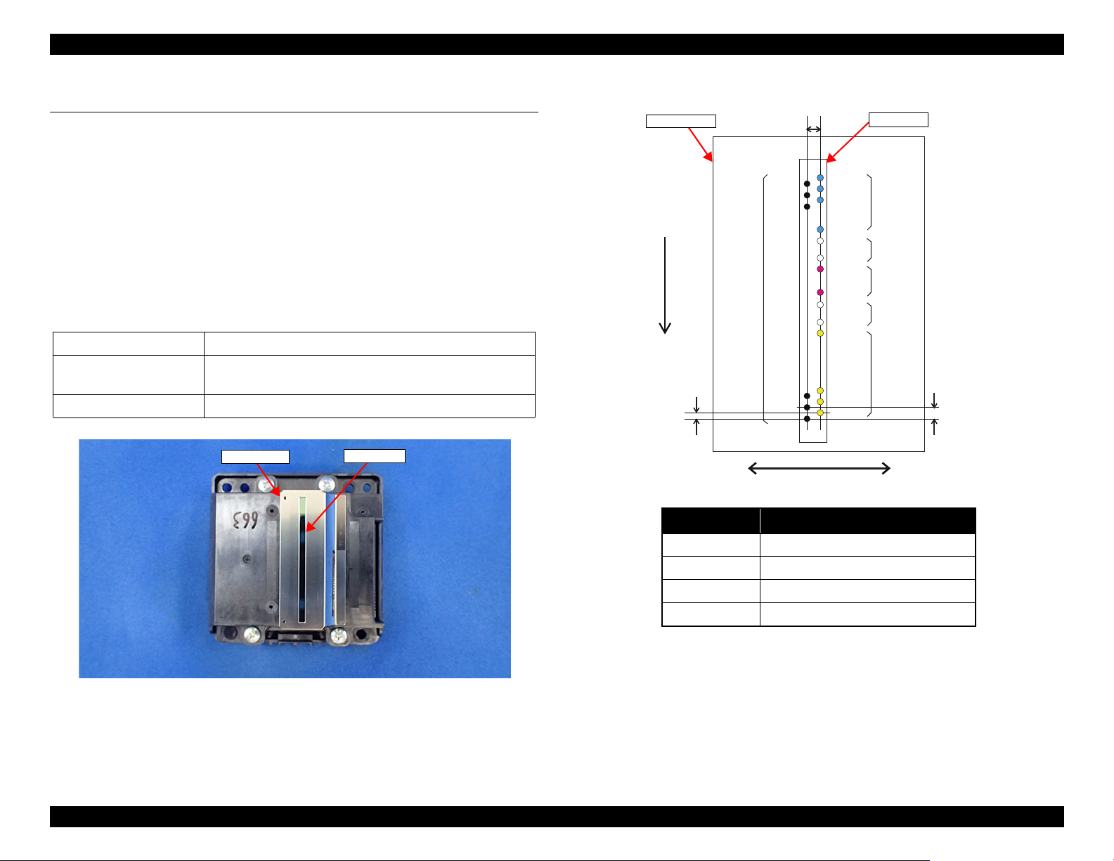
1.1.1 Print Head
μTFP1S head (p 13) is used for ET-4750/ET-4760/L6190/ST-4000 series/ET-
3750/ET-3760/L6170/ST-3000 series/ET-3700/ET-3710/L6160 series.
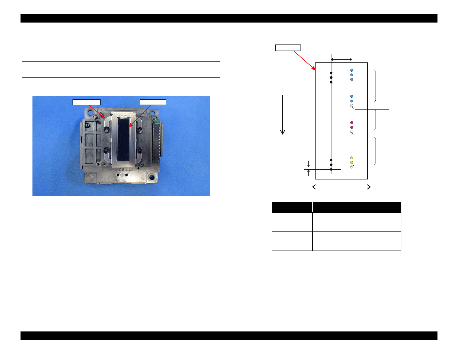
F2 head (p 14) is used for ET-2750/ET-2760/L4160/ST-2000 series/ET-2700/
L4150 series.
ET-4750/ET-4760/L6190/ST-4000 series/ET-3750/ET-3760/L6170/ST-
3000 series
Color Four colors: black (Bk), cyan (C), magenta (M), yellow (Y)
Number of nozzles 784 nozzles:
Nozzle pitch 300 dpi
/ET-3700/ET-3710/L6160 series
Table 1-1. Nozzle Configuration
400 nozzles for Bk, and 128 nozzles for each of Y, M, and C
Operating Principles Printer Mechanism Overview 13
Figure 1-1. μTFP1S Print Head appearance
Figure 1-2. Nozzle layout (seen from the rear side)
Confidential
Page 14
EPSON ET-4750/4760/3750/3760/3700/3710/2750/2760/2700/L6190/L6170/L6160/L4160/L4150/ST-4000/ST-3000/ST-2000 series Revision I
Nozzle plate
Cover Head
Black
Column A Column B
Carriage movement direction
Paper feed direction
Column Color
ABk
B #1 - #60 Y
B #62 - #120 M
B #122 - #180 C
Yellow
Cyan
Magenta
Not used
Not used
Not used
Nozzle plate
ET-2750/ET-2760/L4160/ST-2000 series/ET-2700/L4150 series
Table 1-2. Nozzle Configuration
Color Four colors: black (Bk), cyan (C), magenta (M), yellow (Y)
Number of nozzles 357 nozzles:
180 nozzles for Bk, 59 nozzles for each Y, M, and C.
Nozzle pitch 180 dpi
0.071 mm
1/360 inch
5.9266 mm
42/180 inch
A#180
A#179
A#178
A#3
A#2
A#1
B#180
B#179
B#178
B#123
B#122
B#121
B#63
B#62
B#61
B#3
B#2
B#1
Figure 1-3. F2 Print Head appearance
Operating Principles Printer Mechanism Overview 14
Figure 1-4. Nozzle layout (seen from the rear side)
Confidential
Page 15
EPSON ET-4750/4760/3750/3760/3700/3710/2750/2760/2700/L6190/L6170/L6160/L4160/L4150/ST-4000/ST-3000/ST-2000 series Revision I
CR Scale
CR Timing Belt
CR Unit
CR Motor
(Backside of the Main Frame)
CR Encoder Sensor
Section view
Main Frame
CR Unit
Main Frame
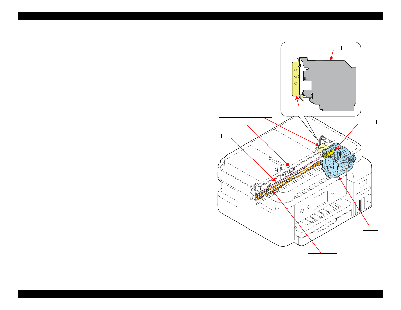
1.1.2 Carriage (CR) Mechanism
The major components of the carriage (CR) mechanism are the CR Unit, CR
Encoder Sensor, CR Scale, CR Motor, and CR Timing Belt. The CR
mechanism is a key mechanism to ensure stable print quality because printing
is performed by moving the CR Unit from side to side.
As shown on the right, Main Frame is holding the upper side and the lower side
of the CR Unit. The CR Unit is attached to the CR Timing Belt that is moved
by the CR Motor so that the assy can move from side to side to print. The
position and speed of the CR Unit are always monitored by the CR Encoder
Sensor and the CR Scale, and the CR Motor is controlled in accordance with
the information acquired by the CR Encoder Sensor.
Operating Principles Printer Mechanism Overview 15
Figure 1-5. Carriage (CR) mechanism
Confidential
Page 16
EPSON ET-4750/4760/3750/3760/3700/3710/2750/2760/2700/L6190/L6170/L6160/L4160/L4150/ST-4000/ST-3000/ST-2000 series Revision I
Cassette
Slider Trans
Holder Cam Assy
PF Motor
PF Roller
Pick up Roller Assy
Intermediate roller
(inside the Duplex Unit)
EJ Roller
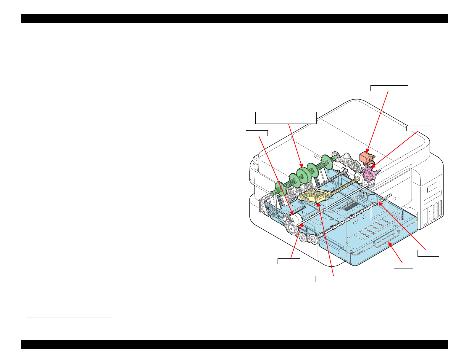
1.1.3 Paper Loading/Feed Mechanism
Paper loading mechanism differs between ET-4750/ET-4760/L6190/ST-4000
series/ET-3750/ET-3760/L6170/ST-3000 series/ET-3700/ET-3710/L6160
series and ET-2750/ET-2760/L4160/ST-2000 series/ET-2700/L4150 series.
ET-4750/ET-4760/L6190/ST-4000 series/ET-3750/ET-3760/L6170/ST-3000
series/ET-3700/ET-3710/L6160 series employ the front paper loading, and ET2750/ET-2760/L4160/ST-2000 series/ET-2700/L4150 series employ the rear
paper loading. The both paper loading mechanisms are driven by the PF Motor,
and the motor is also used for driving the paper feeding mechanism.
The printer is also equipped with a paper feeding mechanism for auto
duplexing as well as other existing products. The mechanism flips paper after
printing on the front side is finished, and feeds the paper to print on the back
side.
ET-4750/ET-4760/L6190/ST-4000 series/ET-3750/ET-3760/L6170/ST-
3000 series/ET-3700/ET-3710/L6160 series
A sheet of paper is fed inside the printer from the Paper Cassette by the Pick up
Roller Assy.
*1
Because the Pick up Roller Assy needs to be stopped each after it feeds a sheet
of paper, it is necessary to control the transmission of a drive force to the assy.
The control is achieved by the Slider Trans and the Holder Cam Assy. When
the Slider Trans is moved by the CR Unit, the state of engagement between the
transmission gear on the Trans Slider and the Pick up Roller driving gear
changes, which enables switching between transmitting the PF Motor driving
force to the Pick up Roller Assy and not transmitting it.
Even after the CR Unit is detached from the Slider Trans for printing, position
of the Slider Trans is kept by the Holder Cam Assy.
The paper fed by the Pick up Roller Assy is conveyed by the intermediate
roller, PF Roller, and EJ Roller which are included in the paper feeding
mechanism.
*1. See "1.3 Paper Loading/Feed Mechanism" (p 23) for more details.
Figure 1-6. Paper loading/feed mechanism (1)
Operating Principles Printer Mechanism Overview 16
Confidential
Page 17
EPSON ET-4750/4760/3750/3760/3700/3710/2750/2760/2700/L6190/L6170/L6160/L4160/L4150/ST-4000/ST-3000/ST-2000 series Revision I
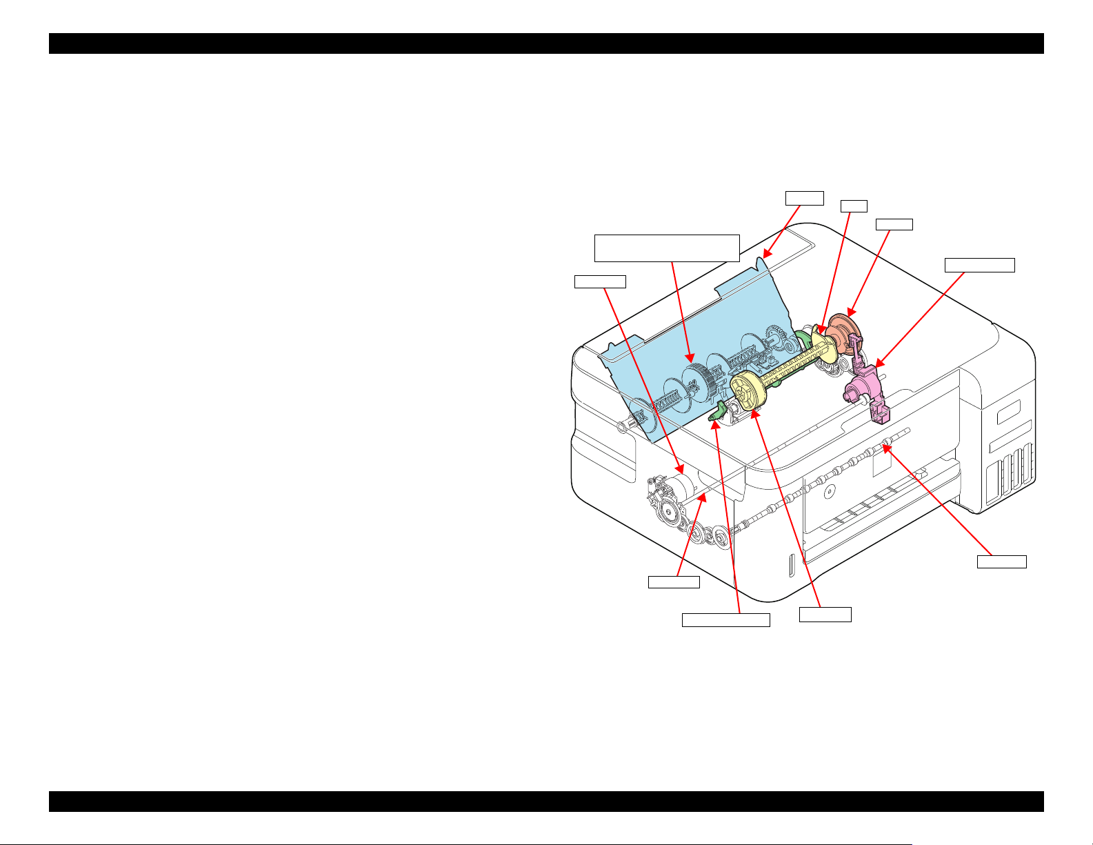
Paper Back Lever
Hopper
PF Motor
PF Roller
LD Roller
Intermediate roller
(inside the Duplex Unit)
EJ Roller
Change Lever
Clutch
Cam
ET-2750/ET-2760/L4160/ST-2000 series/ET-2700/L4150 series
Paper is fed inside the printer from the ASF Rear by the LD Roller.
The ASF Rear is equipped with a Hopper, Paper Back Lever, Change Lever,
LD Roller, and clutch. The Change Lever and the clutch work for transmitting
a driving force from the PF Motor to the LD Roller and for not transmitting it.
The Hopper and the Paper Back Lever driven by the cam on the LD Roller
Shaft prevent multi-feed and ensure accurate paper feeding.
Paper fed by the ASF Rear is conveyed by the PF Roller and the EJ Roller
which are included in the paper feeding mechanism.
Unlike the front paper loading, intermediate roller is used only when flipping
paper for duplex printing.
Figure 1-7. Paper loading/feed mechanism (2)
Operating Principles Printer Mechanism Overview 17
Confidential
Page 18
EPSON ET-4750/4760/3750/3760/3700/3710/2750/2760/2700/L6190/L6170/L6160/L4160/L4150/ST-4000/ST-3000/ST-2000 series Revision I
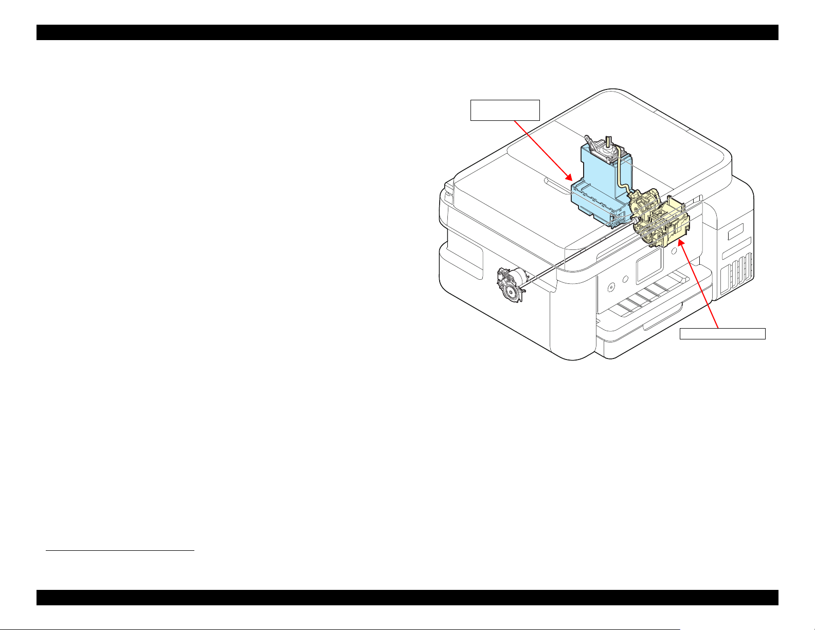
Ink system mechanism
Maintenance Box/
Porous Pad Assy
1.1.4 Ink System Mechanism
The major components of the ink system mechanism*1 are a cap, pump unit,
and waste ink tube.
The ink system mechanism employs the slide type capping. When the CR Unit
returns to its capping position (home position), the Print Head is capped. The
pump mechanism, wiper mechanism, and the CR Lock mechanism are driven
by the PF Motor to clean the Print Head.
Waste ink sucked when cleaning the Print Head is collected in the Maintenance
Box/Porous Pad Assy through the pump mechanism.
User replaceable Maintenance Box is installed to ET-4750/ET-4760/L6190/
ST-4000 series/ET-3750/ET-3760/L6170/ST-3000 series/ET-3700/ET-3710/
L6160 series. A CSIC mounted on the Maintenance Box keeps track of how
much waste ink has been collected.
On the other hand, the Porous Pad that cannot be replaced by user is installed to
ET-2750/ET-2760/L4160/ST-2000 series/ET-2700/L4150 series. The
EEPROM on the Main Board keeps track of how much waste ink has been
collected.
Figure 1-8. Ink system mechanism
*1. See "1.4 Ink System Mechanism" (p 34) for more details.
Operating Principles Printer Mechanism Overview 18
Confidential
Page 19
EPSON ET-4750/4760/3750/3760/3700/3710/2750/2760/2700/L6190/L6170/L6160/L4160/L4150/ST-4000/ST-3000/ST-2000 series Revision I
A
1
B
C
2
3
4
5
6
7
8
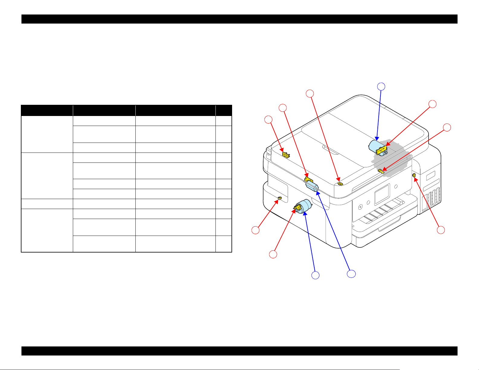
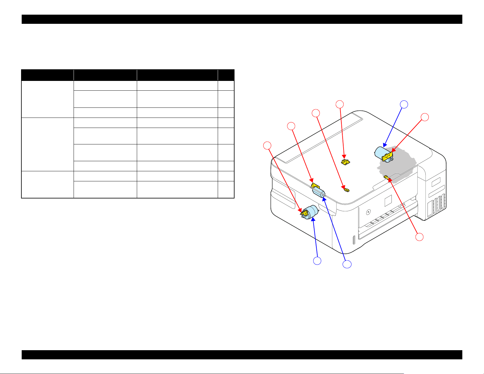
1.1.5 List of Motor and Sensor
This section describes the types and positions of the motors and sensors.
ET-4750/ET-4760/L6190/ST-4000 series/ET-3750/ET-3760/L6170/ST-
3000 series/ET-3700/ET-3710/L6160 series
Table 1-3. Motor and Sensor List
(ET-4750/ET-4760/L6190/ST-4000 series/ET-3750/ET-3760/L6170/ST-3000
series/ET-3700/ET-3710/L6160 series)
Mechanism name Motor/sensor name Motor/sensor type No.
Carriage
mechanism
CR Motor DC Motor A
CR Encoder Transmission-type photo
interrupter
PW Sensor Reflection-type photo interrupter 2
Paper loading/feed
mechanism
Others Ink Cover Open Sensor Mechanical contact 6
Scanner SCN Motor DC Motor C
PF Motor DC Motor B
PF Encoder Transmission-type photo
interrupter
Cassette Sensor Mechanical contact 4
PE Sensor Reflection-type photo interrupter 5
SCN Motor Encoder Transmission-type photo
interrupter
ADF PE Sensor Transmission-type photo
interrupter
1
3
7
8
Figure 1-9. List of motor and sensor
(ET-4750/ET-4760/L6190/ST-4000 series/ET-3750/ET-3760/L6170/ST-
3000 series/ET-3700/ET-3710/L6160 series)
Operating Principles Printer Mechanism Overview 19
Confidential
Page 20
EPSON ET-4750/4760/3750/3760/3700/3710/2750/2760/2700/L6190/L6170/L6160/L4160/L4150/ST-4000/ST-3000/ST-2000 series Revision I
A
1
B
C
2
3
4
5
6
ET-2750/ET-2760/L4160/ST-2000 series/ET-2700/L4150 series
Table 1-4. Motor and Sensor List (ET-2750/ET-2760/L4160/ST-2000 series/ET-
2700/L4150 series)
Mechanism name Motor/sensor name Motor/sensor type No.
Carriage
mechanism
Paper loading/feed
mechanism
Scanner SCN Motor DC Motor C
CR Motor DC Motor A
CR Encoder Transmission-type photo
interrupter
PW Sensor Reflection-type photo interrupter 2
PF Motor DC Motor B
PF Encoder Transmission-type photo
interrupter
ASF Rear Paper existence
Sensor
PE Sensor Reflection-type photo interrupter 5
SCN Motor Encoder Transmission-type photo
Mechanical contact 4
interrupter
1
3
6
Figure 1-10. List of motor and sensor
(ET-2750/ET-2760/L4160/ST-2000 series/ET-2700/L4150 series)
Operating Principles Printer Mechanism Overview 20
Confidential
Page 21
EPSON ET-4750/4760/3750/3760/3700/3710/2750/2760/2700/L6190/L6170/L6160/L4160/L4150/ST-4000/ST-3000/ST-2000 series Revision I
Scanner Unit
CIS Sensor
SCN Motor
ADF Unit
ADF PE Sensor
Pick up Roller
EJ Roller
PF Roller
SCN Motor
EJ Roller
Pick up Roller
Transmission
gear
ADF Document
Lever
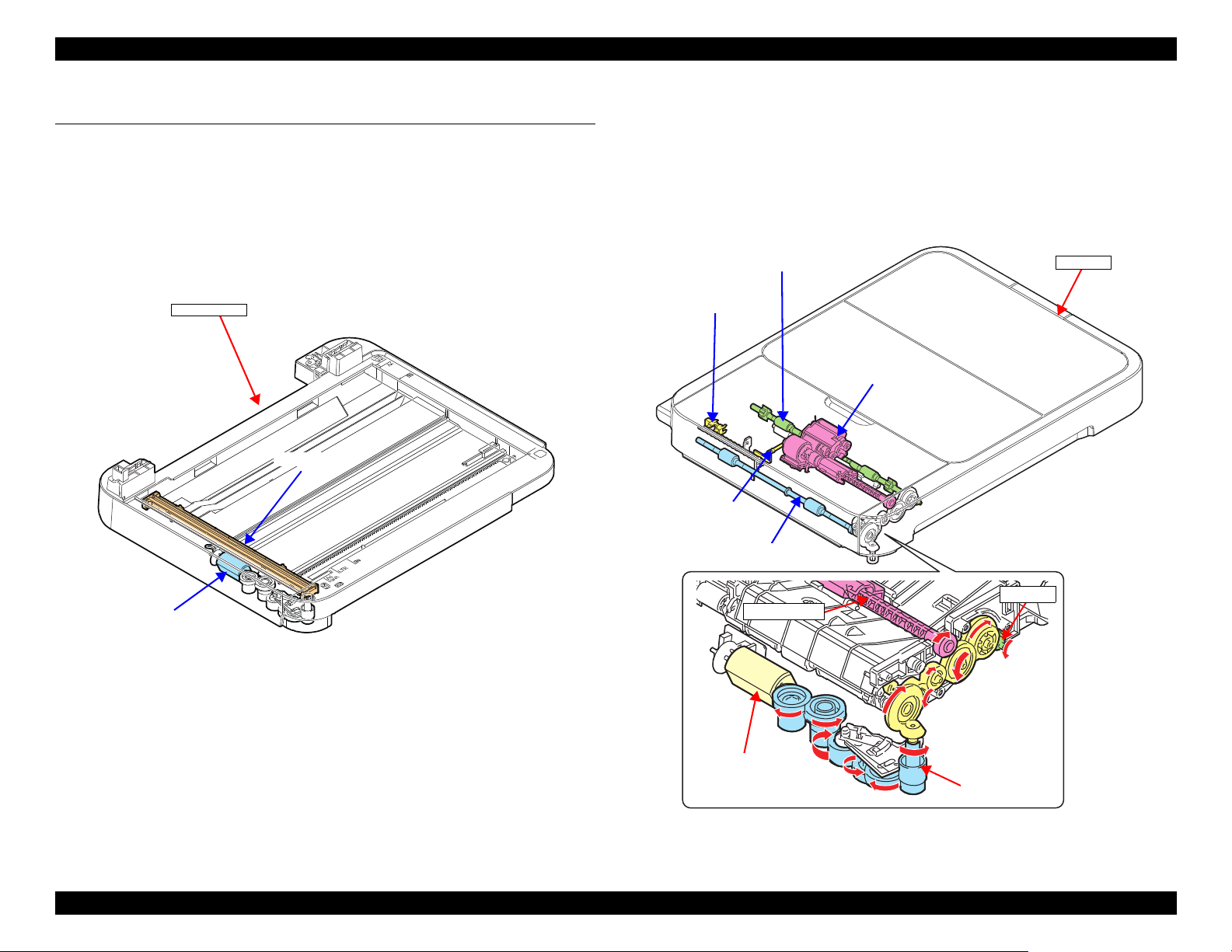
1.2 Scanner/ADF Overview
1.2.1 Scanner Mechanism
The scanner mechanism consists of a CIS sensor that scans documents and the
SCN motor that drives the scanner carriage. The CIS sensor and the SCN motor
are integrated as the scanner carriage, and it moves along the rail on the scanner
housing to scan documents.
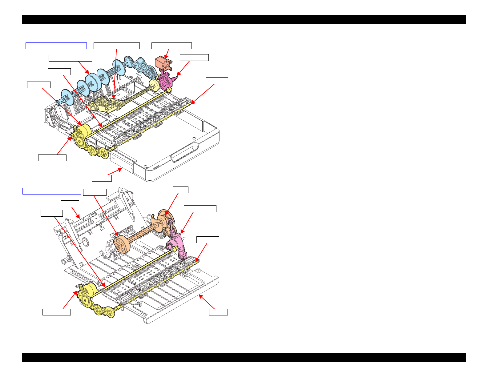
1.2.2 ADF Mechanism (ET-4750/ET-4760/L6190/ST-4000 series/ET-3750/ET-3760/L6170/ST-3000 series only)
The PF Roller, EJ Roller, and Pick up Roller of the ADF mechanism are driven
by the SCN Motor. The drive force of the motor is transmitted through the
transmission gear. The ADF mechanism does not support auto duplex
scanning.
Figure 1-11. Scanner mechanism
Figure 1-12. ADF mechanism
Operating Principles Scanner/ADF Overview 21
Confidential
Page 22
EPSON ET-4750/4760/3750/3760/3700/3710/2750/2760/2700/L6190/L6170/L6160/L4160/L4150/ST-4000/ST-3000/ST-2000 series Revision I
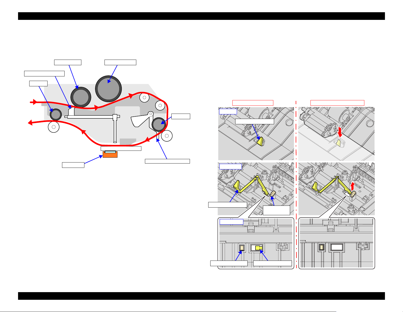
Pick up Roller Separation roller
PF Roller
EJ Roller
CIS Sensor
Lever of ADF PE Sensor
ADF Document Lever
No document on ADF
Document is present on ADF
ADF document lever
ADF document lever
Sub document
lever
Sub document lever ADF document lever
ADF top
ADF inside
ADF bottom
When scanning document, the document is fed inside the ADF as shown
below.
Figure 1-13. Document Feed Path
Presence or absence of document on the ADF is detected by the ADF
Document Lever and the scanner CIS Sensor. The lever moves up or down
depending on the presence or absence of document, and the end of the lever is
scanned by the CIS Sensor. According to the scan result, the printer determines
whether document is present or not.
Additionally, there is a Sub Document Lever beside the ADF Document Lever.
If the CIS Sensor cannot scan the end of the Sub Document Lever, the printer
determines that the scanner (SCN) unit is open or the CIS Sensor is
malfunctioning.
Operating Principles Scanner/ADF Overview 22
Figure 1-14. ADF document lever
Confidential
Page 23

EPSON ET-4750/4760/3750/3760/3700/3710/2750/2760/2700/L6190/L6170/L6160/L4160/L4150/ST-4000/ST-3000/ST-2000 series Revision I
1.3 Paper Loading/Feed Mechanism
1.3.1 Overview
1.3.1.1 Paper Loading Method
Paper loading method differ between ET-4750/ET-4760/L6190/ST-4000
series/ET-3750/ET-3760/L6170/ST-3000 series/ET-3700/ET-3710/L6160
series and ET-2750/ET-2760/L4160/ST-2000 series/ET-2700/L4150 series,
but the both paper loading mechanisms are driven by the PF Motor.
Table 1-5. Paper Loading Method and Drive Force
Drive
force
(motor)
PF Motor PF encoder/
Motor control
PF scale
Front paper loading
• Turn the Slider Trans to
ASF mode, drive the
Pick up Roller Assy, and
load paper from the
cassette.
• Paper loaded from the
cassette is fed to the PF
Roller by the
intermediate roller
inside the duplex unit.
• Drive the PF Roller/EJ
Roller to convey the
paper.
Paper loading operation
model
Rear paper loading
model
• Drive the LD Roller and
load paper from the ASF
Rear.
• Drive the Hopper/Paper
Back Lever to prevent
multi-feed.
• Drive the PF Roller/EJ
Roller to convey the
paper.
• To flip paper for duplex
printing, drive the
intermediate roller
inside the duplex unit.
The paper is flipped and
then fed to the PF
Roller.
The following describes which paper loading method is used
for which model.
Front paper loading
ET-4750/ET-4760/L6190/ST-4000 series/ET-3750/ET3760/L6170/ST-3000 series/ET-3700/ET-3710/L6160
series/
Rear paper loading
ET-2750/ET-2760/L4160/ST-2000 series/ET-2700/L4150
series
Operating Principles Paper Loading/Feed Mechanism 23
Confidential
Page 24
EPSON ET-4750/4760/3750/3760/3700/3710/2750/2760/2700/L6190/L6170/L6160/L4160/L4150/ST-4000/ST-3000/ST-2000 series Revision I
Intermediate roller
Pick up Roller Assy
PF Roller
EJ Roller
PF Motor
Holder Cam Assy
Slider Trans
Cassette
PF Encoder
Hopper
LD Roller
Change Lever
Clutch
PF Encoder
PF Roller
EJ Roller
Stacker
Front paper loading model
Rear paper feeding model
Figure 1-15. Paper loading/feed mechanism
Operating Principles Paper Loading/Feed Mechanism 24
Confidential
Page 25
EPSON ET-4750/4760/3750/3760/3700/3710/2750/2760/2700/L6190/L6170/L6160/L4160/L4150/ST-4000/ST-3000/ST-2000 series Revision I
Cassette
EJ Roller
Star Wheel
Holder Assy
PF Roller
Intermediate roller
PE Sensor
Pick up Roller Assy
Stacker
EJ Roller
Star Wheel
Holder Assy
PF Roller
PE Sensor
LD Roller
Hopper
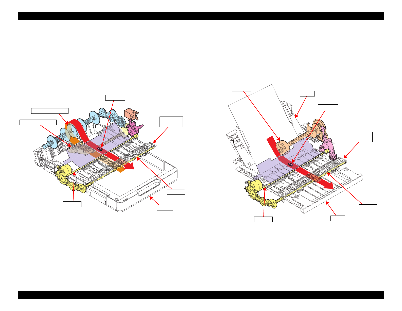
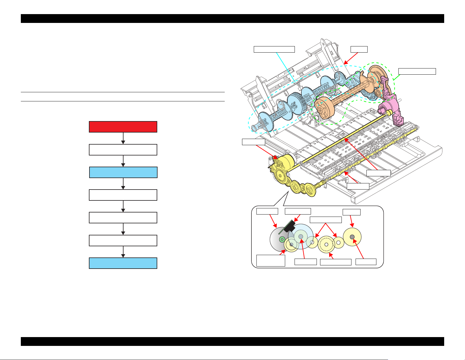
1.3.1.2 Paper Feed Path
1.3.1.2.1 Front Paper Loading
Paper loaded into the cassette is fed to the intermediate roller by the Pick up
Roller Assy, and then arrives at the PE Sensor position.
Next, skew is corrected, and printing on the paper is performed while the paper
is being fed by the PF Roller and EJ Roller/Star Wheel Holder Assy, then the
paper is ejected to the Stacker.
1.3.1.2.2 Rear Paper Loading
Paper put on the Hopper is fed by the LD Roller and arrives at the PE Sensor
position.
Next, skew is corrected, and printing on the paper is performed while the paper
is being fed by the PF roller and EJ Roller/Star Wheel Holder Assy, then the
paper is ejected to the Stacker.
Operating Principles Paper Loading/Feed Mechanism 25
Figure 1-16. Paper feed path of front paper loading
Figure 1-17. Paper feed path of rear paper loading
Confidential
Page 26
EPSON ET-4750/4760/3750/3760/3700/3710/2750/2760/2700/L6190/L6170/L6160/L4160/L4150/ST-4000/ST-3000/ST-2000 series Revision I
EJ Roller
Star Wheel
Holder Assy
PF Roller
PE Sensor
Intermediate roller
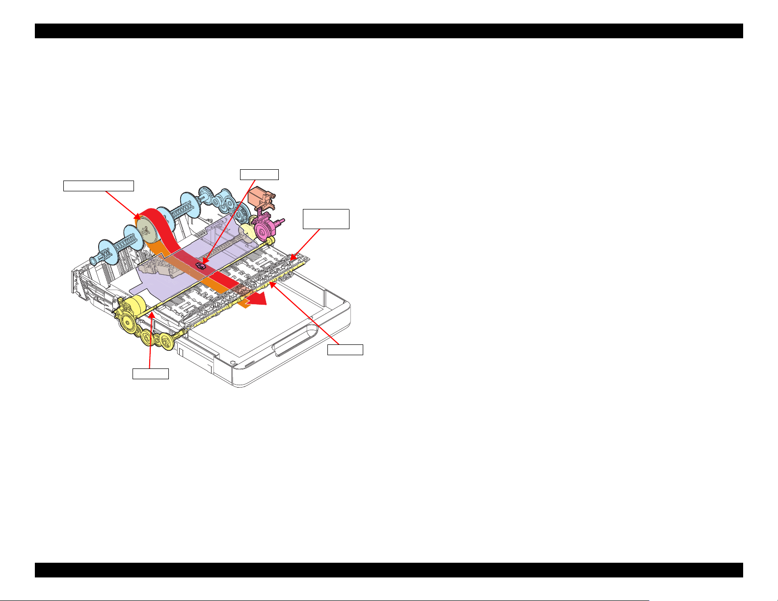
1.3.1.2.3 Paper Loading Path for Auto Duplex Printing
When printing on one side is finished, the printer waits for the ink on the one
side to dry keeping the paper nipped between the PF Roller and Driven Roller.
After a predetermined drying time has passed, the PF Roller and EJ Roller are
rotated in the reverse direction to pull the paper inside the auto duplex unit.
When the leading edge of the paper is detected by the PE Sensor, skew is
corrected, and then printing on the back side is performed.
Figure 1-18. Paper feed path for auto duplex printing (back side printing)
Operating Principles Paper Loading/Feed Mechanism 26
Confidential
Page 27
EPSON ET-4750/4760/3750/3760/3700/3710/2750/2760/2700/L6190/L6170/L6160/L4160/L4150/ST-4000/ST-3000/ST-2000 series Revision I
PF Motor
Compound gear PF1
PF Roller
Spur gear PF1
Spur gear PF2
EJ Roller
Spur gear PF1
PF Roller
PF Motor PF Encoder
Compound gear
PF1
Spur gear PF2
Spur gear
PF1
EJ gear
EJ Roller
PF Roller
EJ Roller
Duplex unit system
Pick up Roller Assy system
PF Motor
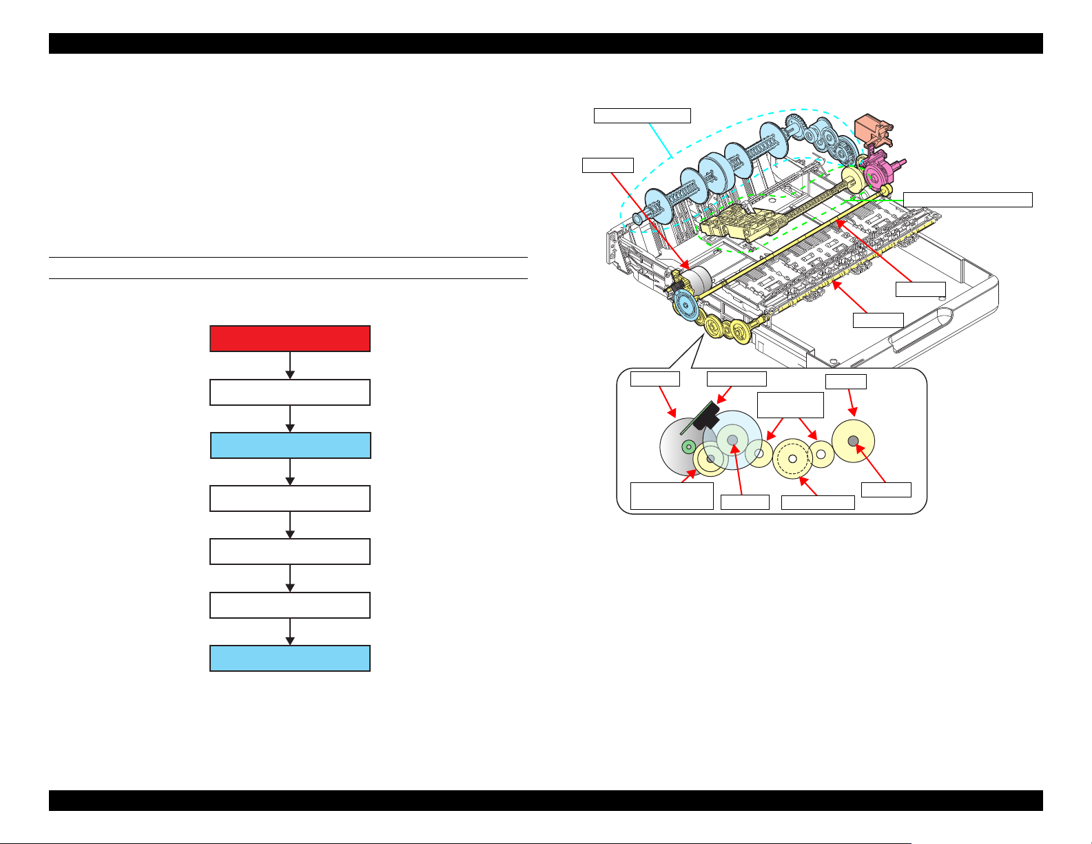
1.3.2 Operation Principle
1.3.2.1 Drive Path
1.3.2.1.1 Drive Path of Front Paper Loading Model
The drive force of the PF Motor is transmitted to the PF Roller and EJ Roller
through the compound gear and the spur gear, and then transmitted from the PF
Roller to the paper feed mechanism. There are two drive paths; duplex unit
system
DRIVE PATH FROM PF MOTOR TO PF ROLLER/EJ ROLLER
(p 28) and Pick up Roller Assy system (p 29).
Figure 1-20. Drive path from PF Motor to PF Roller/EJ Roller (2)
Figure 1-19. Drive path from PF Motor to PF Roller/EJ Roller (1)
Operating Principles Paper Loading/Feed Mechanism 27
Confidential
Page 28
EPSON ET-4750/4760/3750/3760/3700/3710/2750/2760/2700/L6190/L6170/L6160/L4160/L4150/ST-4000/ST-3000/ST-2000 series Revision I
PF Roller (spur gear 9)
Compound gear 28.8-14.4
Spur gear 22.8
One way clutch
External gear B (80 digit side)
Intermediate roller
Spur gear 17.28
Sun gear
Planetary gear (x5)
Planetary gear (x5)
External gear A (0 digit side)
Spur gear 17.28
Spur gear 17.28
Spur gear 16/spur gear duplex
One way
clutch
PF Roller
Intermediate Roller
PF Motor
Structure of one way clutch
Planetary gear
Sun gear
External
gear A
External
gear B
External
gear A
External
gear B
Sun gear
Rotational direction of sun gear and motion
of external gear seen from 0 digit side
Idle
Idle
Clockwise
Counterclockwise
Rotate
Rotate
Compound gear
28.8-14.4
Spur gear 22.8
Spur gear 17.28
Spur gear 17.28
Spur gear 16/Spur gear duplex
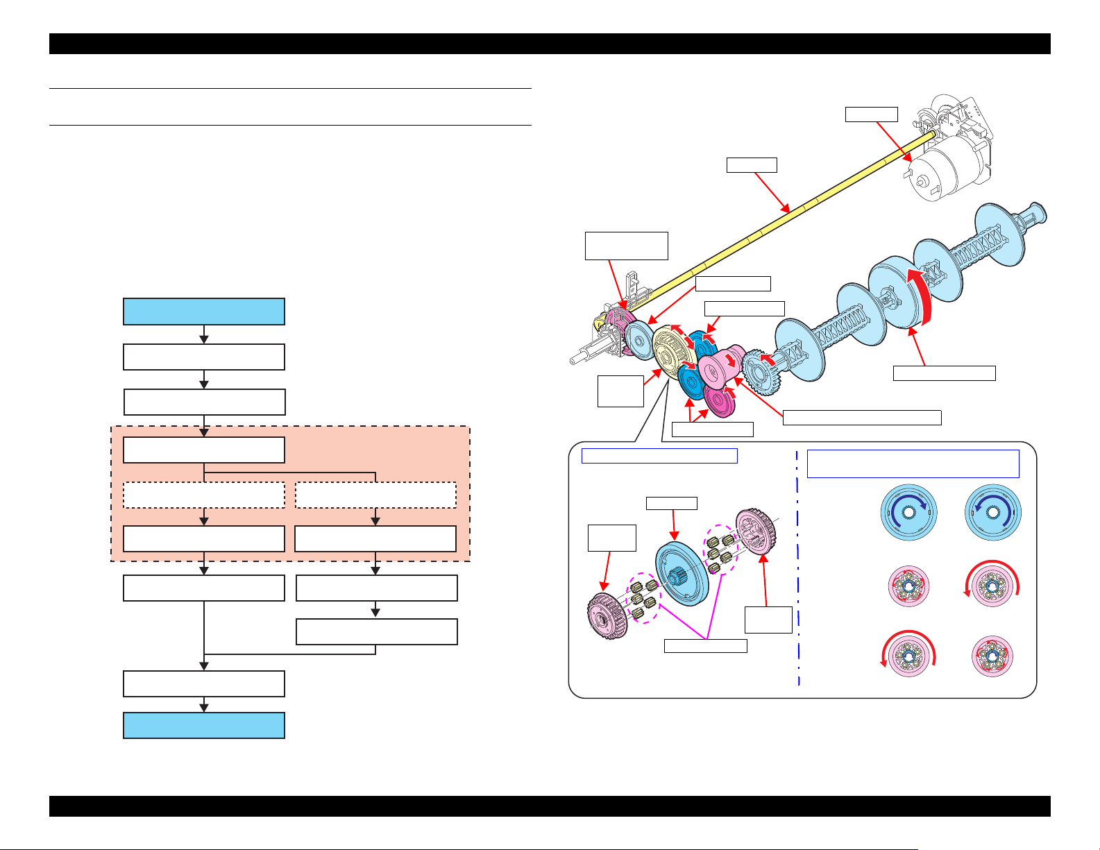
DRIVE PATH FROM PF ROLLER TO INTERMEDIATE ROLLER
(DUPLEX UNIT SYSTEM)
The intermediate roller always rotates in the paper feed direction because of the
one way clutch, regardless of the PF roller rotational direction.
The one way clutch is consist of the sun gear, the external gear (x2) on both
sides of the sun gear, and the planetary gear (x5 each) inside the external gear.
When the sun gear rotates, either one of the external gears idle being
disengaged from the planetary gears, while the external gear on the other side
rotates being engaged with the planetary gears. In this way, the one way clutch
is designed to rotate either one of the two external gears at a time, and which
one to rotate depends on the rotational direction of the sun gear.
Figure 1-21. Drive Path From PF Roller to Intermediate Roller (1)
Operating Principles Paper Loading/Feed Mechanism 28
Figure 1-22. Drive Path From PF Roller to Intermediate Roller (2)
Confidential
Page 29

EPSON ET-4750/4760/3750/3760/3700/3710/2750/2760/2700/L6190/L6170/L6160/L4160/L4150/ST-4000/ST-3000/ST-2000 series Revision I
PF Roller (spur gear 9)
Compound gear 28.8-14.4
Spur gear 17.6 (Slider Trans)
One way clutch
Sun gear
Planetary gear (x3)
External gear
Spur gear 28
Pick up drive shaft
Spur gear 16B
Spur gear 16
Spur gear 16B
Spur gear 16
Pick up Roller
One way clutch
When drive force
of PF Motor is not
transmitted
Spur gear 17.6
(Slider Trans)
Pick up drive shaft
Spur gear
16
Spur gear 16B
PF Roller
Spur gear 28
Compound gear 28.8-14.4
CR Unit
Planetary
gear
Sun gear
External gear
Holder
Cam Assy
Pick up Roller
DRIVE PATH FROM PF ROLLER TO PICK UP ROLLER (PICK UP ROLLER
ASSY SYSTEM)
If the Pick up Roller Assy is always driven by the PF motor, it continues
feeding paper without stopping regardless of the progress of printing on the
previous sheet. To prevent this, the Slider Trans interrupts the motor drive to
the Pick up Roller Assy when the assy needs to stop.
While the Pick up Roller Assy needs to move, the Slider Trans is pulled toward
the opposite side of the carriage home with the tension spring. The
transmission gear interlocked with the Slider Trans engages with the Pick up
Roller driving gear (one way clutch) that moves the Pick up Roller Assy, so the
Pick up Roller Assy can be driven by the PF Motor. If the CR Unit pushes the
Change Lever to the 0 digit side, the transmission gear disengages from the one
way clutch. As a result, the driving force of the PF Motor is shut down.
The CR Unit pushes the Slider Trans to the 0 digit side to stop the Pick up
Roller Assy after a sheet of paper is fed into the printer, however, the CR Unit
cannot stay at the position because it needs to move for printing. Therefore,
instead of the CR Unit, the Change Lever’s disengaged status is kept by the
cam of the Holder Cam Assy during printing.
The one way clutch controls the Pick up Roller to rotate only in the paper feed
direction. The operation principle and the structure are basically the same with
the one used in the drive path to the intermediate roller
(p 28). Therefore, while
the PF Roller is rotating in the direction opposite to the paper feed direction,
the Pick up Roller does not rotate even when the drive force is transmitted
through the Slider Trans.
Operating Principles Paper Loading/Feed Mechanism 29
Figure 1-23. Drive path from PF roller to Pick up Roller Assy (1)
Figure 1-24. Drive path from PF roller to Pick up Roller Assy (2)
Confidential
Page 30
EPSON ET-4750/4760/3750/3760/3700/3710/2750/2760/2700/L6190/L6170/L6160/L4160/L4150/ST-4000/ST-3000/ST-2000 series Revision I
PF Motor
Compound gear PF1
PF Roller
Spur gear PF1
Spur gear PF2
EJ Roller
Spur gear PF1
PF Roller
PF Motor
PF Encoder
Compound
gear PF1
Spur gear PF2
Spur gear PF1
EJ gear
EJ Roller
PF Roller
EJ Roller
Duplex unit system
ASF Rear system
PF Motor
Hopper
1.3.2.1.2 Drive Path of Rear Paper Loading Model
The drive path of the rear paper loading model is mostly the same with the
front paper loading model. The driving force of the PF Roller is transmitted to
the PF Roller and the EJ Roller through the compound gear and the spur gear,
and then transmitted from the PF Roller to the paper feed mechanism. There
are two drive paths; duplex unit system
(p 31) and ASF Rear system (p 32).
DRIVE PATH FROM PF MOTOR TO PF ROLLER/EJ ROLLER
Figure 1-25. Drive path from PF Motor to PF Roller/EJ Roller (1)
Figure 1-26. Drive path from PF Motor to PF Roller/EJ Roller (2)
Operating Principles Paper Loading/Feed Mechanism 30
Confidential
Page 31

EPSON ET-4750/4760/3750/3760/3700/3710/2750/2760/2700/L6190/L6170/L6160/L4160/L4150/ST-4000/ST-3000/ST-2000 series Revision I
PF Roller (spur gear PF)
Compound gear 27.2-22.2
Compound gear 38.4-15.6
One way clutch
External gear B (80 digit side)
Intermediate roller
Spur gear 21.6
Sun gear
Planetary gear (x5)
Planetary gear (x5)
Spur gear 21.6
Spur gear 21.6
Spur gear16/spur gear duplex
External gear A (0 digit side)
One way
clutch
PF Roller
Intermediate roller
PF Motor
Planetary gear
Sun gear
External
gear A
External
gear B
External
gear A
External
gear B
Sun gear
Rotate
Idle
Clockwise
Counterclockwise
Idle
Rotate
Compound gear
38.4-15.6
Spur gear 21.6
Spur gear
21.6
Spur gear 16/Spur gear duplex
Compound gear
27.2-22.2
Change
Lever
Structure of one way clutch
Rotational direction of sun gear and motion
of external gear seen from 0 digit side
DRIVE PATH FROM PF ROLLER TO INTERMEDIATE ROLLER
(DUPLEX UNIT SYSTEM)
The intermediate roller always rotates in the paper feed direction because of the
one way clutch, regardless of the PF roller rotational direction.
The one way clutch is consist of the sun gear, the external gear (x2) on both
sides of the sun gear, and the planetary gear (x5 each) inside the external gear.
When the sun gear rotates, either one of the external gears idle being
disengaged from the planetary gears, while the external gear on the other side
rotates being engaged with the planetary gears. In this way, the one way clutch
is designed to rotate either one of the two external gears at a time, and which
one to rotate depends on the rotational direction of the sun gear.
Figure 1-27. Drive Path From PF Roller to Intermediate Roller (1)
Operating Principles Paper Loading/Feed Mechanism 31
Figure 1-28. Drive Path From PF Roller to Intermediate Roller (2)
Confidential
Page 32
EPSON ET-4750/4760/3750/3760/3700/3710/2750/2760/2700/L6190/L6170/L6160/L4160/L4150/ST-4000/ST-3000/ST-2000 series Revision I
PF Roller (spur gear PF)
Compound gear 27.2-22.2 (Change Lever)
Compound gear 38.4-15.6
LD Roller
Clutch
Paper Back Lever
Hopper
Cam A
Cam B
Hopper
Clutch
CR Unit
PF Roller
PF Motor
Paper Back Lever
LD Roller
Compound
gear
38.4-15.6
Cam A
Cam B
Change Lever
Compound
gear 27.2-22.2
Compound
gear 38.4-15.6
PF Roller
Compound
gear 27.2-22.2
Clutch Change Lever
Pawl of clutch
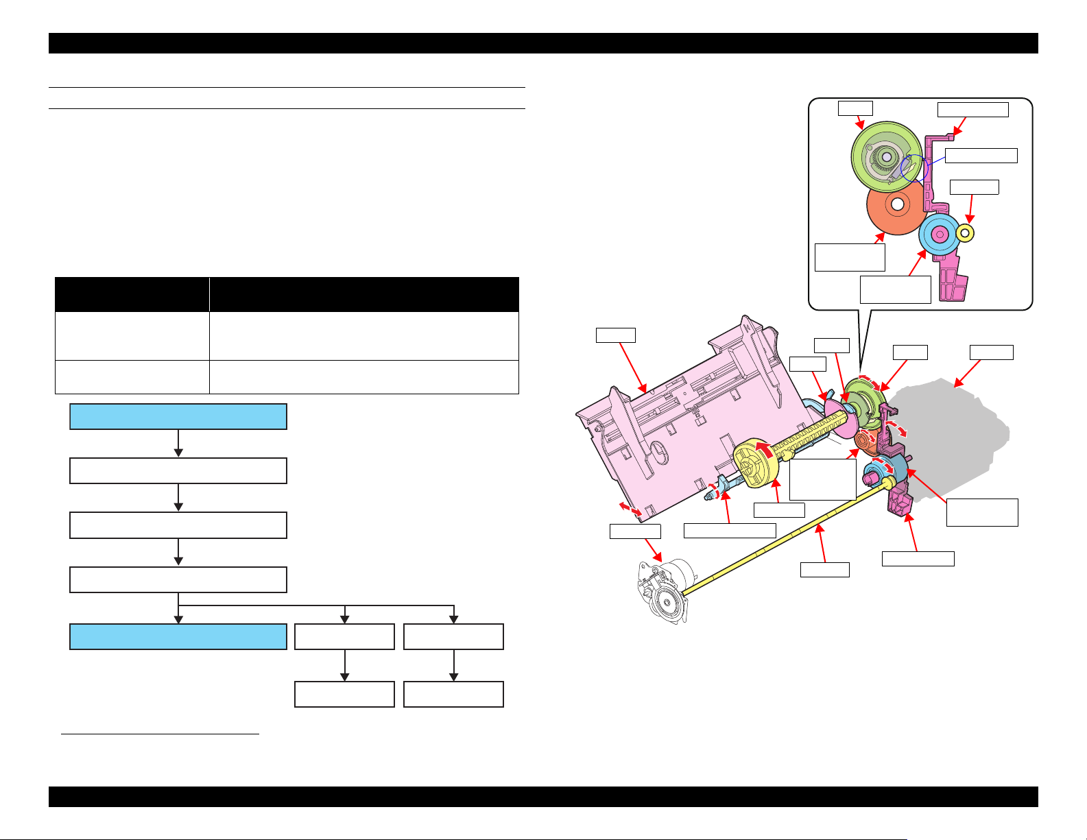
DRIVE PATH FROM PF ROLLER TO LD ROLLER (ASF REAR SYSTEM)
The drive force of the PF Motor is transmitted to the LD Roller through the PF
Roller, Change Lever (compound gear 27.2-22.2) and the clutch. The Hopper
and the Paper Back Lever is driven by the cam linked to the LD Roller.
Since the PF Motor also drives the paper feed mechanism and the ink system
mechanism, transmission of the drive force to the LD Roller is controlled by
the Change Lever and the clutch so that the LD Roller rotates only when
loading paper.
Relation between the rotational direction of the PF Motor and the motion of the
*1
LD Roller are shown below.
PF Motor rotational
direction
Paper feed direction
Opposite to the paper feed
direction
Motion of LD Roller
The clutch transmits or does not transmit the drive force to
the LD Roller in relation to the Change Lever. When
transmitted, the LD Roller rotates in the paper feed direction.
The LD Roller does not rotate since the drive force is
disengaged by the clutch.
Figure 1-29. Drive Path From PF Roller to LD Roller (1)
*1. See " Operation of Paper Loading Mechanism" (p 33) for more details.
Figure 1-30. Drive Path From PF Roller to LD Roller (2)
Operating Principles Paper Loading/Feed Mechanism 32
Confidential
Page 33

EPSON ET-4750/4760/3750/3760/3700/3710/2750/2760/2700/L6190/L6170/L6160/L4160/L4150/ST-4000/ST-3000/ST-2000 series Revision I
Normal operation: ASF locked
Operation at paper loading: ASF unlocked
CR Unit
(home position)
PF Roller
Change Lever
LD Roller
Clutch
Pawl of clutch
CR Unit
(retracts from the home position to the
80 digit side.)
The lock of the Change Lever is
disengaged.
Operation at paper loading: ASF drive state
OPERATION OF PAPER LOADING MECHANISM
The following describes how the Change Lever and the clutch work for
transmitting or not transmitting the PF Motor drive force to perform paper
feeding.
Drive force control by the Change Lever and clutch
When the Change Lever holds the pawl of the clutch (ASF lock state), the
clutch is disengaged and the drive force of the PF Motor is not transmitted to
the LD Roller.
When the Change Lever releases the pawl of the clutch (ASF unlock/ASF drive
state), the clutch is engaged and the drive force of the PF Motor is transmitted
to the LD Roller.
Normal operation
While the CR Unit is in the home position, it prevents the Change Lever from
leaning toward the front side. Therefore, the Change Lever keeps the ASF lock
state regardless of the rotation direction of the PF Motor and the clutch is
disengaged to shut off the drive force of the PF Motor to the LD Roller.
Even when the CR Unit is not in the home position for printing or other reason,
the ASF lock state is kept to shut off the drive force to the LD Roller as long as
the PF Motor rotates CW (in the paper feed direction).
Operation at paper loading
When the printer starts loading paper, the CR Unit moves away from the home
position and the PF Motor starts rotating CCW. This causes the Change Lever
to lean toward the front side and the ASF is unlocked. Then, the clutch is
engaged, and the drive force of the PF Motor is transmitted to the LD Roller.
After the ASF is unlocked, the PF Motor starts rotating CW, and the LD Roller
starts rotating in the paper feed direction. The LD Roller and the Retard Roller
separate a sheet of paper from the other sheets on the Hopper and feed it into
the printer. At this point, the Change Lever has returned to the original position
(leaning toward the rear side).
After the LD Roller rotates once, the Change Lever holds the pawl of the clutch
and the ASF is locked. Then, the drive force of the PF Motor to the LD Roller
is shut off, and the paper loading ends.
*1
Figure 1-31. Operation of Paper Loading Mechanism
*1. The LD Roller is shaped in a character of D. Because of this shape, the LD Roller and Retard Roller can release a
sheet when the sheet reaches the PF Roller so that the paper feed by the PF Roller is not affected.
(seen from 80 digit side)
Operating Principles Paper Loading/Feed Mechanism 33
Confidential
Page 34

EPSON ET-4750/4760/3750/3760/3700/3710/2750/2760/2700/L6190/L6170/L6160/L4160/L4150/ST-4000/ST-3000/ST-2000 series Revision I
Capping
mechanism/
cap slider
Maintenance Box
(Waste Ink Tank)
Pump mechanism
Wiper mechanism
CR Lock mechanism
Adapter
Print Head
Front paper loading
model
(ET-4750/ET-4760/
L6190/ST-4000 series/
ET-3750/ET-3760/
Rear paper loading
model
(ET-2750/ET-2760/
L4160/ST-2000 series/
Pump mechanism
Cap Slider
Wiper
Cap
CR Lock
Cap Slider
Wiper
Cap
CR Lock
Pump mechanism
1.4 Ink System Mechanism
1.4.1 Overview
1.4.1.1 Mechanical Configuration
The ink system mechanism of this product employs the sliding type*1 and
consists of the CR Lock mechanism, wiper mechanism, capping mechanism,
and pump mechanism.
All the mechanisms are driven by the PF Motor. The drive force of the PF
Motor is transmitted to each mechanism via transmission parts, such as the
pump-drive compound gear, clutch gear, and cam. Additionally, ET-4750/ET4760/L6190/ST-4000 series/ET-3750/ET-3760/L6170/ST-3000 series/ET3700/ET-3710/L6160 series utilize a user-replaceable Maintenance Box (waste
ink pad) that retains waste ink from the cap.
Figure 1-32. Ink system mechanism (simplified model)
*1. There are two types of the capping: sliding type and direct acting type. In the sliding type, the Print Head is capped
(the cap is moved up) when the CR pushes the cap slider. In the direct acting type, the cap moves up and down independently of the CR and caps the Print Head.
Operating Principles Ink System Mechanism 34
Figure 1-33. Ink system mechanism
Confidential
Page 35
EPSON ET-4750/4760/3750/3760/3700/3710/2750/2760/2700/L6190/L6170/L6160/L4160/L4150/ST-4000/ST-3000/ST-2000 series Revision I
Maintenance Box/
Porous Pad Assy
Paper Guide Lower Porous Pad
Paper Guide Lower Porous Pad D
Paper Guide Lower Porous Pad B/C
1.4.1.2 Cleaning
Clogging of nozzles on the Print Head occurs due to air bubbles generated
inside the ink path of the Print Head, or an increase in ink viscosity caused by
drying of ink. To prevent the clogging or clean the clogged nozzles, various
types of cleaning (CL) are performed at different times as described in the table
below.
Table 1-6. Print Head cleanings
CL Type Purpose Explanation
Initial ink charge To fill the head with ink Performed after the printer is
powered at the first time.
Timer cleaning (TCL)
Manual
cleaning
*2
(MCL)
Regular cap suction To prevent ink leakage
Flushing To prevent ink inside non-
*1. To save ink, the time between the timer cleanings is becoming longer on the most newer printers. This is achieved
by adopting the plastic that have the function to suppress the growth of air bubbles inside the Print Head and by improving in shape of the ink supply nozzles.
*2. When carrying out manual cleaning, CL1 → CL2 → CL3 are automatically selected and performed in order. How-
ever, in the following conditions, they may not be carried out in this order.
(EX) CL3 may change to CL2 depending on the ink remaining quantity and conditions of maintenance counter and
others.
If the interval between cleaning is more than a specified period, then this may not be counted as continuous.
*3. “Main suction” is a suction operation that sucks up ink from cartridges to the Print Head, and at the same time, sucks
out air bubbles inside the Print Head and thick ink inside the nozzles.
*4. “Wiping” removes ink attached to the Print Head nozzle surface.
*5. “Cap suction” is a suction operation that sucks ink out of the cap.
*6. “Small amount suction” is a suction operation performed to eject tiny air bubbles from the Print Head. Ink amount
sucked by this operation is less than that by the “Main suction”.
*7. Some off-carriage type printers use a choke valve mechanism to perform the cleaning.
*1
To eject bigger air bubbles
inside the Print Head
CL1 To restore a proper
convex meniscus of ink at
the tip of nozzles
CL2 To eject air bubbles inside
the Print Head
*7
CL3
To eject air bubbles inside
the ink supply nozzles
from the cap
used nozzles from
increasing its viscosity
Performed according to the printing
time and time elapsed since the last
cleaning.
Main suction*3(short) → Wiping*4
→ Cap suction*5 → Small amount
suction*6 → Cap suction
Main suction (middle) → Wiping →
Cap suction → Small amount
suction → Cap suction
Main suction (long) → Wiping →
Cap suction → Small amount
suction → Cap suction
Sucks out ink pooling inside the cap
due to head flushing operations or
the like.
The Print Head is controlled to fire
ink droplets from the nozzles
periodically.
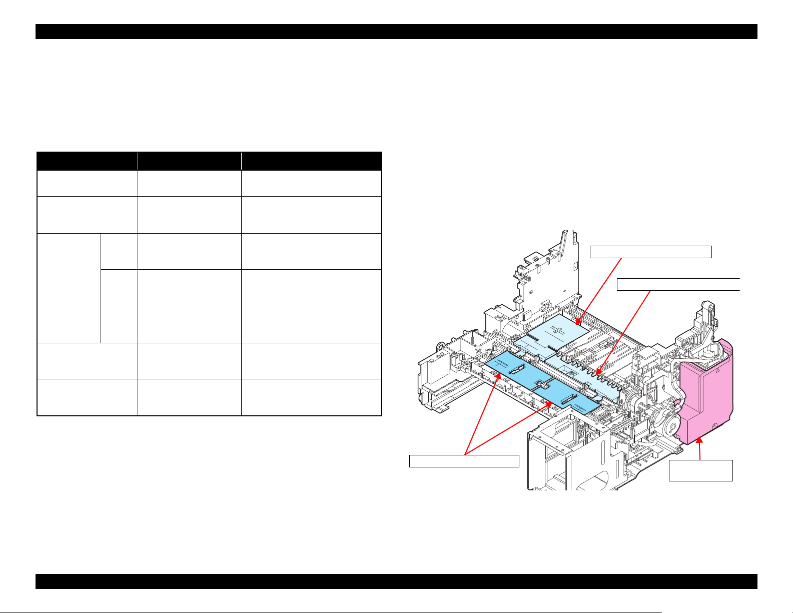
1.4.1.3 Controlling Waste Ink
Ink used by cleanings (waste ink) is absorbed by the waste ink pad. If the
absorbed amount exceeds the limit of the waste ink pad, leakage of the waste
ink can occur. To prevent this, the printer firmware has a counter to counts the
waste ink amount taking evaporation into account, The count value is retained
in the Maintenance Box CSIC (ET-4750/ET-4760/L6190/ST-4000 series/ET3750/ET-3760/L6170/ST-3000 series/ET-3700/ET-3710/L6160 series only)
and in the EEPROM.
Another waste ink produced by borderless printing is absorbed by absorbers
attached on the Paper Guide Front and the rear side of the printer. For the
borderless printing, the printer makes an image slightly expand all the way to
the edge of the paper, therefore, the image edge portions not printed on paper
must be absorbed. Some printers also have the counter for this waste ink
amount.
Figure 1-34. Position of Waste Ink Pad for Borderless Printing
If each counter reaches its limit, a maintenance error occurs and replacement of
the maintenance box, or replacement of the waste ink pad and counter reset will
be required.
Operating Principles Ink System Mechanism 35
Confidential
Page 36

EPSON ET-4750/4760/3750/3760/3700/3710/2750/2760/2700/L6190/L6170/L6160/L4160/L4150/ST-4000/ST-3000/ST-2000 series Revision I
PF Roller (spur gear PF)
Front paper loading model:
compound gear 28.8-14.4
Rear paper loading model:
compound gear 27.2-22.2
Spur gear
Compound gear equipped with a clutch
+ cam
Wiper
mechanism
CR Lock
mechanism
Pump driving gear
Pump mechanism
PF Roller
Compound gear 28.8-14.4
Compound gear 27.2-22.2
Pump driving gear
Pump driving gear
Cap slider
Spur gear
Spur gear PF
PF Roller
Spur gear
Compound gear equipped
with a clutch + cam
Cap slider
Wiper
Wiper
CR Lock
Compound gear equipped
with a clutch + cam
CR Lock
Cap
Cap
Front paper loading model
Rear paper loading model
Spur gear PF
1.4.2 Operating Principles
1.4.2.1 Drive Path
The ink system mechanism is driven by the PF Motor.
To the pump mechanism, the drive force is constantly transmitted via the PF
Roller, compound gear, Pump driving gear, and etc.
The drive force is transmitted to the wiper mechanism and CR Lock
mechanism via the PF Roller, spur gear, compound gear equipped with a
clutch, and cam. The clutch works in accordance with movement of the cap
slider and cam, and interrupts the drive force upon completion of the
movement.
Figure 1-35. Drive path (1)
The table below shows how each mechanism operates according to the
rotational direction of the PF Motor.
Table 1-7. PF motor rotational direction and operation of the ink system
Mechanism
Wiper Moves down Moves up (wiping position)
Pump Release Suction
CR Lock Unlocks the CR Locks the CR
*1. Rotational direction seen from output shaft
Operating Principles Ink System Mechanism 36
Rotational direction of the PF Motor
CW CCW
*1
Figure 1-36. Drive path (2)
Confidential
Page 37

EPSON ET-4750/4760/3750/3760/3700/3710/2750/2760/2700/L6190/L6170/L6160/L4160/L4150/ST-4000/ST-3000/ST-2000 series Revision I
Pump motor counter-clock wise rotation (suction)
Rotates flattening
the tube.
Rotates without
flattening the tube.
Pump motor clock wise rotation (release)
Spur gear 21.6
Pump tube
Pump shaft
Pump spring (x2)
Pump cam
Pump pulley
Pump frame
The cap slider pressed by the CR unit
moves upward and cap the Print Head.
CR unit moves to the home position
(0 digit side)
Ink system (cap unit)
Cap slider
CR Unit
Print Head
1.4.2.2 Operation of Each Mechanism
1.4.2.2.1 Pump Mechanism
The pump mechanism sucks ink from the Print Head at cleaning.
The drive force from the pump-drive compound gear is transmitted to the pump
shaft via the timing plate. This timing plate allows the pump-drive compound
gear to start rotating at the different timing from the pump shaft. After the PF
Motor rotates for a while, the pump unit starts its operation.
When the pump motor rotates counter-clock wise as seen from the output-shaft
side of the motor, the drive force via the pump-drive compound gear rotates the
pump pulley to flatten the tube to suck the air (to generate negative pressure)
inside the tube. When the pump motor rotates clock wise, the pump pulley does
not flatten the tube, and the negative pressure is released.
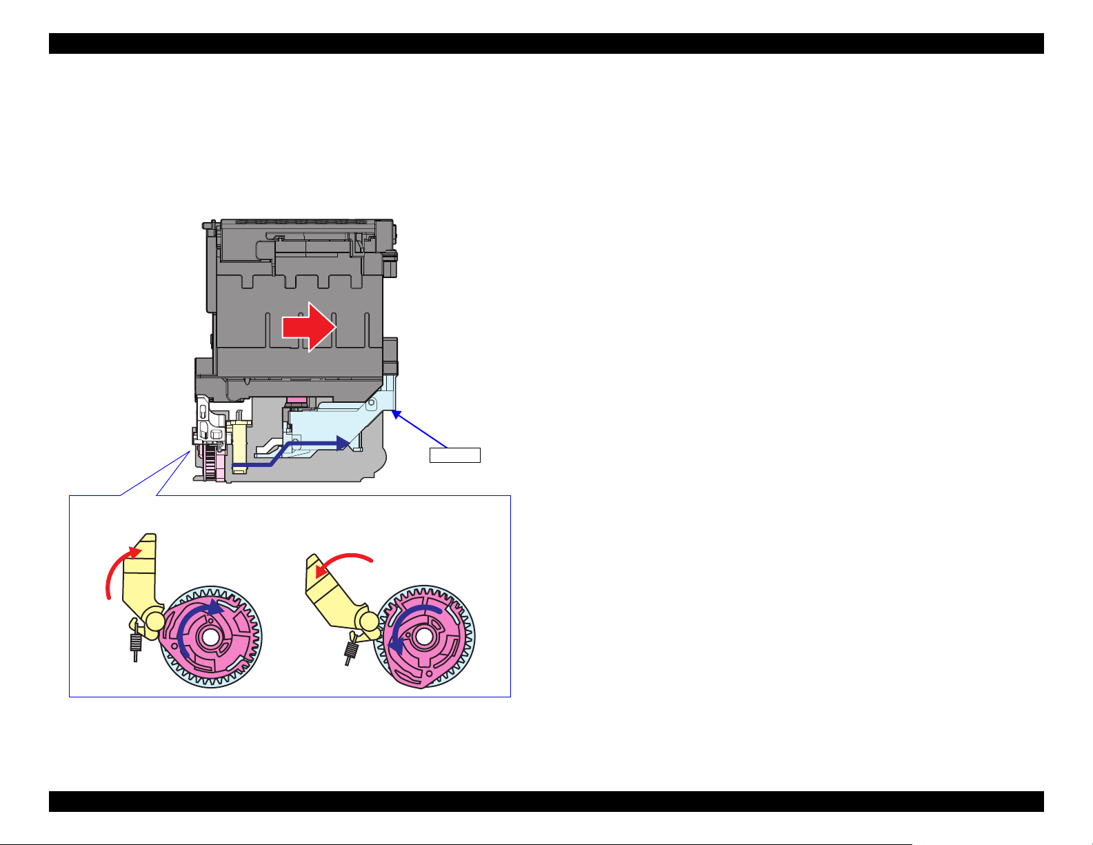
1.4.2.2.2 Capping Mechanism
When the CR Unit returns to its home position, the cap slider pressed by the
CR Unit moves upward to cap the Print Head. When the CR Unit moves away
from the home position, the cap slider moves downward and the Print Head is
uncapped and released from the vacuum state. The ink system for this product
does not have a valve for canceling the vacuum state, but the cap slider moved
by the CR Unit provides the same function as the valve.
Operating Principles Ink System Mechanism 37
Figure 1-37. Pump mechanism operations
Figure 1-38. Capping mechanism operations
Confidential
Page 38

EPSON ET-4750/4760/3750/3760/3700/3710/2750/2760/2700/L6190/L6170/L6160/L4160/L4150/ST-4000/ST-3000/ST-2000 series Revision I
Carriage is not at home (Clutch throw-out) Cap slider is lifted (Clutch engaged)
PF motor rotates CW to move the wiper up
PF motor rotates CCW to move the wiper down
Cap slider
Cam
Compound gear equipped with a clutch
Cam groove (1)
Wiper salient
Cap slider salient
Cam groove (1)
Wiper salient
The cap slider movement causes its salient that secures the cam to come off the cam groove (2),
so the cam is rotated being driven by the gear engaged.
The cam rotates CW when the PF motor rotates CW and the wiper is
moved up.
The cam rotates CCW when the PF motor rotates CCW and the wiper is
moved down.
Even if the cap slider goes down after releasing the cam to make it rotate, the cap slider
salient does not engage with the cam groove (2) (the cam is not locked). The cam groove
(2) shape is designed to engage with the cap slider salient only when the wiper goes
down.
Cam groove (2)
Cap slider salient
Wiper salient
Wiper salient
The cap slider salient secures the cam, so the gear of the compound gear set is thrown out and
the PF motor drive is not transmitted to the cam.
Cam groove (2)
1.4.2.2.3 Wiper Mechanism
The wiper moves in synchronization with the capping operation. The PF motor drive transmitted through the compound gear set and cam equipped with clutch
moves the wiper up or down.
Operating Principles Ink System Mechanism 38
Figure 1-39. Wiper mechanism operation
Confidential
Page 39
EPSON ET-4750/4760/3750/3760/3700/3710/2750/2760/2700/L6190/L6170/L6160/L4160/L4150/ST-4000/ST-3000/ST-2000 series Revision I
Only when the cap slider goes up, the cam can move to lock or unlock the CR.
Unlocking
Locking
Cap slider
1.4.2.2.4 CR Lock Mechanism
The CR Lock operates in synchronization with the cap unit. It locks or unlocks
the CR using the PF motor drive force transmitted through the cam of the
compound gear set equipped with a clutch. For information on how the cap
slider and the cam are related to each other, see
"1.4.2.2.3 Wiper Mechanism"
(p 38).
Figure 1-40. CR Lock mechanism operation
Operating Principles Ink System Mechanism 39
Confidential
Page 40

TROUBLESHOOTING
CHAPTER
2
Confidential
Page 41

EPSON ET-4750/4760/3750/3760/3700/3710/2750/2760/2700/L6190/L6170/L6160/L4160/L4150/ST-4000/ST-3000/ST-2000 series Revision I
2.1 Troubleshooting
This section describes the troubleshooting workflow and fatal error
information.
2.1.1 Troubleshooting Workflow
The following page describes the troubleshooting workflow. Follow the flow
when troubleshooting problems.
This flowchart is compiled based on the following
contents.
• Our experience regarding the quality problem.
• ESK’s repair data.
• Printer Mechanism specification for the product.
If the reason for the return is evident, first check the
phenomenon user claims recurs, then proceed to the
troubleshooting.
If the SCN error is the reason for the return, since the
printer may be the cause of the error, check the Fatal
Error Code history saved in the EEPROM with the
adjustment program before starting the troubleshooting.
" Workflow when the Power is ON (Printer) (p42) "
" Workflow for Scanner Errors when the Power is ON (p45) "
" Workflow for Errors when Printing Starts (p46) "
Troubleshooting Troubleshooting 41
Confidential
Page 42

EPSON ET-4750/4760/3750/3760/3700/3710/2750/2760/2700/L6190/L6170/L6160/L4160/L4150/ST-4000/ST-3000/ST-2000 series Revision I
A
(p 43)
Error?
*1
031006
Error
031004
Error
Paper jam
Maintenance error
Stop
Fatal error occurred?
Error?
Release CR Lock
Stop
Yes
Yes
Yes
Yes
Yes
No
No
No
No
No
No
Yes
Yes
No
Seeks home position
Power on (printer)
031006
031004
xxxxxx
xxxxxx
xxxxxx
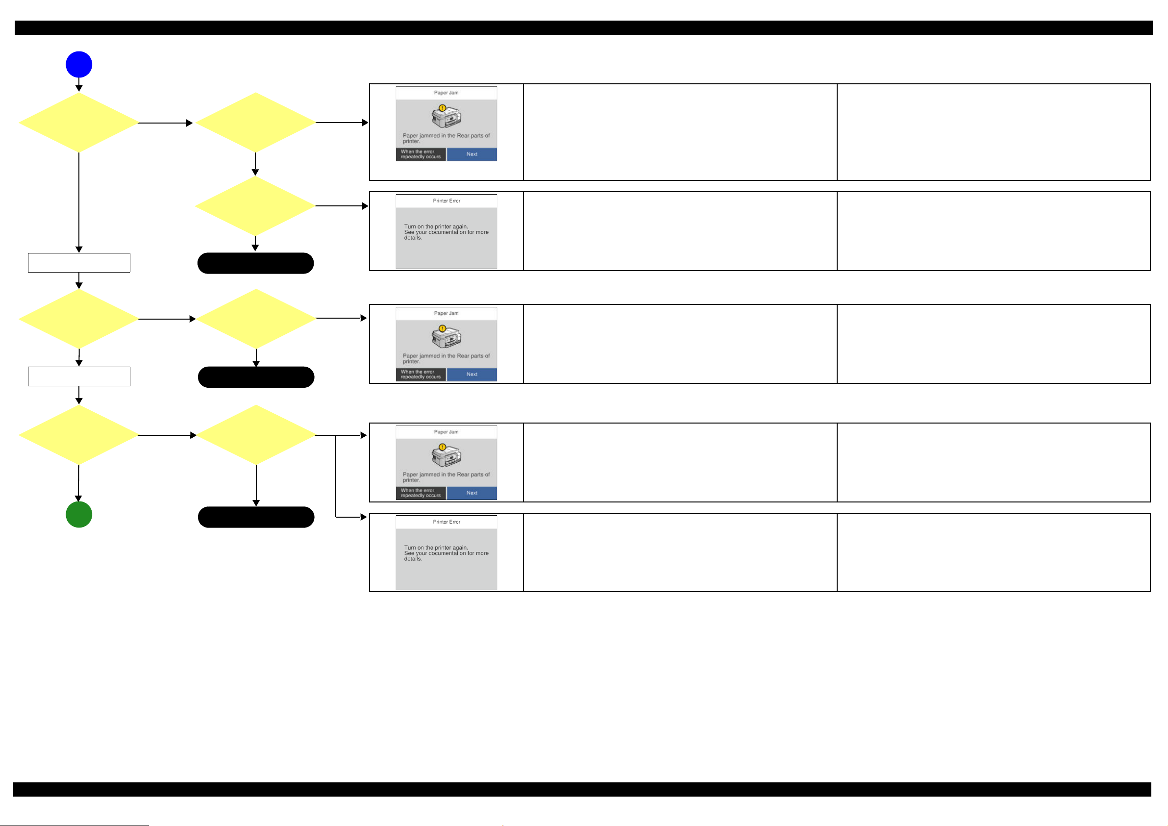
2.1.1.1 Workflow when the Power is ON (Printer)
Fatal Errors may occur during the Mechanism operation. When an error occurred other
than the timing shown below, check the Mechanism for other causes.
See "2.1.1.2 Workflow for Scanner Errors when the Power is ON (p45) " since the scanner
operates during the power-on sequence of the printer.
Displayed screen may differ by the model.
Blowout of a fuse of the Main Board Check disconnection, breakage, slant connection, or damage contact of the Head
FFC.
Print head is broken.
Replace the Main Board.
Detects abnormality of the Head Thermistor. Check disconnection, breakage, slant connection, or damage contact of the Head
FFC.
Print head is broken.
Replace the Main Board.
Paper jam
PE Sensor adjustment value abnormality
Check if the PE Sensor is broken, or its cable is disconnected, broken or connected
at an angle.
Replace the Main Board.
Maintenance error Replace the Maintenance Box.
Main or borderless maintenance error Reset the Main or Borderless Waste Ink Pad Counter.
1. PF Motor did not rotate. (Error Code: 000041)
2. PF Motor rotated too fast. (Error Code: 000041)
3. PF Motor rotated. (Error Code: 000043)
1. Disconnection of the PF Motor Connector, load is too large for the paper feed
mechanism.
2. Replace the PF Encoder FFC, the PF Encoder.
3. Replace the PF Motor.
Common: Replace the Main Board.
Note “*1”: Mechanism does not operate yet.
Troubleshooting Troubleshooting 42
Confidential
Page 43
EPSON ET-4750/4760/3750/3760/3700/3710/2750/2760/2700/L6190/L6170/L6160/L4160/L4150/ST-4000/ST-3000/ST-2000 series Revision I
B
Stop
(p 42)
(p 44)
Error?
Stop
CR reciprocation
*3
Error?
Paper ejection
*2
A
Paper jam
CR error
Error? CR moves?
CR stopped
Stop
Yes
No
No
No
No
No
No
No
Yes
Yes
Yes
Yes
Yes
Yes
xxxxxx
xxxxxx
CR did not function. Remove the tape securing the CR if the error occurs when the printer is powered on
for the first time.
Check whether the CR Lock is released. If not, the PF Motor or the Ink system is
broken.
Check the mechanical load of the CR manually, and check the Ink system also.
CR Motor disconnect, replace the cable.
Replace the CR Motor.
Replace the Main Board.
1. Fatal Error (Error Code: 000025)
2. Fatal Error (Error Code:000023 [Stops with noises.])
3. Fatal Error (Error Code: 000031)
1. Check whether any obstacle exists in the CR motion range.
2. Check whether any problem occurred to the CR Lock and Ink System.
3. Check if the Timing Belt is loose.
4. Clean or replace the CR Encoder Scale.
5. Replace the Main Board.
PE Sensor detected paper presence
Note PF Motor rotates for a while (longer than normal), and then the error occurs.
Check if any obstacle exists in the Paper Path. Remove it if any.
Check PE Sensor FFC disconnection/breakage, or replace the FFC.
Replace the PE Sensor.
Replace the Main Board.
Paper jam error occurred. Check if there is any obstacle in the CR motion range.
Check if the CR Motor gets stuck somewhere when moved by hand.
Check if any heavy load exists in the CR motion range.
Note Perform the corresponding repair.
Fatal Error of CR system occurred. Check if there is any obstacle in the CR motion range.
Check if the CR Motor gets stuck somewhere when moved by hand.
Check if any heavy load exists in the CR motion range.
Note Perform the corresponding repair.
Troubleshooting Troubleshooting 43
Note “*2”: Performed if an abnormality occurred the last time the printer was powered off.
“*3”: CR Unit reciprocates two times quickly when environmental temperature is lower than 5°C or when initial charge is not performed yet.
Confidential
Page 44

EPSON ET-4750/4760/3750/3760/3700/3710/2750/2760/2700/L6190/L6170/L6160/L4160/L4150/ST-4000/ST-3000/ST-2000 series Revision I
Stop
END
(p 43)
Mechanism operation finish
CR Lock
Ink System operation
205102
Error
*5
202620
Error
Error?
Error?
*4
Ink error
Yes
No
Yes
No
Yes
Yes
No
Yes
No
B
202620
205102
<Message>
Refill the ink tank, then select the refilled color on the panel to reset the ink counter.
Fill ink tank(s) with ink up to the upper line.
→Select the color(s) you refilled.
Maintenance Error (ET-4750/ET-4760/L6190/ST-4000 series/ET-3750/ET-3760/L6170/
Replace the Maintenance Box.
ST-3000 series/ET-3700/ET-3710/L6160 series)
<Message>
Maintenance Box is at the end of its service life.
You need to replace it.
EWMB2 (model number)
Maintenance Error (ET-2750/ET-2760/L4160/ST-2000 series/ET-2700/L4150 series)
Replace the Porous Pad Assy.
<Message>
The printer’s ink pad is at the end of its service life.
Please contact Epson Support.
Wireless LAN Board is broken. Check the connection of the Wireless LAN Board.
Replace the Wireless LAN Board.
Card Slot Board is broken. (ET-2750/ET-2760/L4160/ST-2000 series) Check the state of the Card Slot Board FFC.
Replace the Card Slot Board.
Note “*4”: Occurs five to six seconds after the completion of the mechanism operation.
Note “*5”: ET-2750/ET-2760/L4160/ST-2000 series only
Confidential
Troubleshooting Troubleshooting 44
Page 45

EPSON ET-4750/4760/3750/3760/3700/3710/2750/2760/2700/L6190/L6170/L6160/L4160/L4150/ST-4000/ST-3000/ST-2000 series Revision I
Power on (SCN)
Detects Home position
*1
Moves to starting position for
white standard pattern reading
*1
Error?
Reads white standard
pattern
*2
Error?
Moves to the position for
reading home position*2
Error?
Reads home position
*2
END
100016
Error
100017
Error
100032
Error
Stop
Yes
Yes
Yes
Yes
Yes
Yes
No
No
No
No
No
No
100016
100017
100032
2.1.1.2 Workflow for Scanner Errors when the Power is ON
The scanner initial operation and the printer initialization are performed in parallel when
the power is turned on.
Depending on the error type, a scanner error may occur after the printer was repaired
because some of the printer error indications have higher priority (and vice versa).
For repair, replace the SCN Unit.
Measurement failure does not occur when turning the power on. The measurement
sequence occurs when entering the power saving mode.
Home position detection error
SCN CR cannot move to the home position because load is too large.
CIS is broken (cannot read the white standard pattern and home position pattern).
1. Turn the power on with the Document Cover opened.
2. Check if the CIS moves to the left to read the white standard/home patterns.
3. Check if the emission color of the CIS is white (not greenish, reddish, or bluish).
If the light does not look like white, check the SCN FFC for damage, disconnection
or skew.
4. Replace the SCN Unit with a new one.
5. Replace the Main Board with a new one.
Contact detection distance exceeded
Contact detection to the right side has not been completed properly.
Wheel Train of the Drive Mechanism is detached or broken.
SCN Motor Wheel Train is detached or broken.
1. Turn the power on with the Document Cover opened.
2. Check if the SCN CR reaches (comes in contact with) the right side.
3. Check the Wheel Train of the Drive Mechanism for damage.
4. Check the SCN FFC for damage, disconnection or skew.
5. Replace the SCN Unit with a new one.
6. Replace the Main Board with a new one.
LED light lighting failure
SCN FFC disconnection, breakage, slant connection, or damaged contact (CN409).
CIS is broken.
1. Check the color of the LED at power-on.
2. Check the scanner FFC for damage, disconnection or skew.
3. Replace the SCN Unit with a new one.
4. Replace the Main Board with a new one.
Note “*1”: CIS does not light up.
“*2”: CIS lights in greenish white.
Troubleshooting Troubleshooting 45
Confidential
Page 46

EPSON ET-4750/4760/3750/3760/3700/3710/2750/2760/2700/L6190/L6170/L6160/L4160/L4150/ST-4000/ST-3000/ST-2000 series Revision I
Start
Paper feed variable
initialization, paper feed
preparation
Paper feed
Communication Error*1
Error?
Yes
Yes
Yes
No
No
No
Service Error*1
Yes
Network Communication
Error
(p 47)
A
Communication Error
Communication Error
Check the Wi-Fi/network connection
For details, see your documentation
Communication Error
Communication Error
Check the Wi-Fi/network connection
950140
Service Error
The ReadyPrint Service is
unavailable
xxxxxx
2.1.1.3 Workflow for Errors when Printing Starts
Note “*1”: ET-4750U/ET-2750U only
Communication Error
Network problem occurred
Subscription Error : Subscription communication error (950140)
A communication error with the subscription server occurred.
1. Subscription Error : Subscription service error (Opt-Out) (950141)
- Received Opt-out from subscription server.
2. Subscription Error : Subscription service error (Halting) (950142)
- Received halt from subscription server.
3. Subscription Error : Subscription service error (Unregistered) (950143)
- Received unregistered from subscription server.
4. Subscription Error : Subscription service error (Starting up) (950144)
- During communication with the subscription server at startup.
No need for repair actions at repair site. (It does not mean hardware failure. User
needs to check network settings and network connection status.)
No need for repair actions at repair site. (It does not mean hardware failure. User
finds solution on subscription portal site or contacts the call center for solutions.)
No need for repair actions at repair site. (It does not mean hardware failure. User
finds solution on subscription portal site or contacts the call center for solutions.)
Troubleshooting Troubleshooting 46
Confidential
Page 47

EPSON ET-4750/4760/3750/3760/3700/3710/2750/2760/2700/L6190/L6170/L6160/L4160/L4150/ST-4000/ST-3000/ST-2000 series Revision I
Paper Out (2)
Paper Out (1)Error?
Yes
Yes
Yes
No
No
No
Message?
Print
Start Print
Paper jam (1)
Paper jam (2) (3)
Stop
END
No
Yes
Yes
Yes
No
No
(p 46)
A
xxxxxx
Paper out in the Paper Cassette or the Rear Tray
The leading edge cannot be detected with the PE Sensor in the range of the
standard movement.
Paper out in the Paper Cassette or the Rear Tray
The leading edge cannot be detected with the PE Sensor in the range of the
standard movement.
Paper jam occurred in the path until the PE Sensor.
PE Sensor, PW Sensor error
CR system Fatal Error
Paper jam occurred while reversing paper or backside ejecting during paper feeding of
duplex printing.
Refill paper to the Paper Cassette and set the cassette back in place fully.
PE Sensor/PW Sensor FFC disconnected, breakage, slant connection, damaged
contact (CN402/CN303).
Replace the PE Sensor/PW Sensor.
Replace the Main Board.
Refill paper to the Rear Tray and set the Guide Paper back in place fully.
PE Sensor/PW Sensor FFC disconnected, breakage, slant connection, damaged
contact (CN402/CN303).
Replace the PE Sensor/PW Sensor.
Replace the Main Board.
Remove the foreign objects.
PE Sensor/PW Sensor FFC disconnection, breakage, slant connection, damaged
contact (CN402/CN303).
Replace the PE Sensor/PW Sensor.
Troubleshoot and repair the CR system Fatal Error.
Replace the Main Board.
Remove the foreign objects.
Replace the Duplex Unit.
Fatal Error: Head temperature error (031004)
Fatal Error: Head Hot error (before printing) (031001)
Fatal Error: Head Hot error (after flushing) (031002)
Note Head Hot error does not occur when the signals do not flow fully because part or all of the
contact of FFC is covered by foreign objects or the like.
1. Check the Head FFC state (CN301).
2. Replace the Head.
3. Replace the Main Board.
Note Check the procedure in order.
Troubleshooting Troubleshooting 47
Confidential
Page 48

EPSON ET-4750/4760/3750/3760/3700/3710/2750/2760/2700/L6190/L6170/L6160/L4160/L4150/ST-4000/ST-3000/ST-2000 series Revision I
080 HP
080 HP
080 HP
080 HP
080 HP
2.2 Power-On Sequence
This section describes the power-on sequences as reference for
troubleshooting. The preconditions are as follows.
Condition: Power-on sequence (See Table2-1)
No error occurred when you turned on the printer last time and it has been
correctly turned off.
Initial ink charge was done and every tank has sufficient ink.
No paper on the paper path.
The Print Head is capped.
The Carriage is normally fixed by the CR Lock.
Maintenance error recovery has never been performed.
Table 2-1. Normal Power-on Sequence
Operation
1. Checking fuse on the Print Head
1-1.Checks if the fuse on the Print Head circuit boards is blown.*3
*1
2. Checking for waste ink overflow
2-1.Checks the waste ink counter if the waste ink overflow is occurring.
CR Unit/PF Roller
movement and
position
PF Roller
CR Lock
Operation
4-5.The distance from the position where the CR Unit touched to the
Left Frame is regarded as the standard distance from the origin
position, and the home position is fixed. From then on, the CR Unit
position is monitored according to the signals from the CR Encoder.
5. Low temperature operation sequence *
5-1.The CR Unit moves back and forth quickly to near the left frame
two times.
6. Ink system performance while power on
6-1.The CR Unit goes back to the home position.
*1
4
movement and
position
*2
080 HP
080 HP
080 HP
Note *1 : The rotation directions of the PF Motor are as follows.
Clockwise: Paper is fed normally
Counterclockwise: Paper is fed backward
*2 : The conditions of the CR Lock are as follows.
CR Unit/PF Roller
*2
080
HP
CR Unit
Red: CR Lock is set
White: CR Lock is released
*3 : The fatal error occurs if there is a problem such as the fuse blew.
*4 : Executed when the detected temperature is under 5 oC (41oF) by the thermistor on the
Print Head.
3. Releasing the CR Lock
3-1.The PF Motor rotates counterclockwise and releases the CR Lock.
4. Seeking the home position
4-1.The CR Unit moves to the 0-digit side slowly and confirms it
touches the Right Frame.
4-2.The CR Unit moves to the 80-digit side slowly and confirms it does
not touch the foreign material, such as remaining paper.
4-3.The PF Motor rotates clockwise to completely release the CR Lock.
4-4.The CR Unit moves to the 0-digit side slowly and checks it touches
the Right Frame.
Troubleshooting Power-On Sequence 48
080 HP
Confidential
Page 49

EPSON ET-4750/4760/3750/3760/3700/3710/2750/2760/2700/L6190/L6170/L6160/L4160/L4150/ST-4000/ST-3000/ST-2000 series Revision I
Error code
LCD display screen
000021
2.3 Fatal Error Code List
This section describes how to check the fatal error code, description, and the
possible causes.
2.3.1 Displaying the Fatal Error Code
The fatal error code is stored in the EEPROM on the Main Board and can be
read out using the Adjustment Program. When a fatal error occurs, this product
displays the fatal error code automatically on the panel LCD.
2.3.2 Fatal Error Code
This section describes the fatal error code and the possible cause for this
product.
" Scanner (p50) "
" Printer (CR) (p56) "
" Printer (PF) (p59) "
" Printer (PW/PE Sensor) (p61) "
" Printer (Power Supply) (p61) "
" Printer (Head/CSIC) (p62) "
" Printer (Others) (p63) "
" System Error (p63) "
ADF related errors are included in the scanner fatal error
list.
Figure 2-1. Indication of the fatal error code
Troubleshooting Fatal Error Code List 49
Confidential
Page 50

EPSON ET-4750/4760/3750/3760/3700/3710/2750/2760/2700/L6190/L6170/L6160/L4160/L4150/ST-4000/ST-3000/ST-2000 series Revision I
2.3.2.1 Scanner
Error
code
100001
100002 ADF PID reverse error
100003 ADF PID lock error
Error name Possible cause Confirmation procedure Connector No.
ADF PID excess speed
error
Failed to read the SCN motor encoder
1. Contamination of the SCN encoder scale
2. Damage or skew of the SCN encoder FFC
3. Failure of the SCN encoder sensor
Failure of the SCN motor driver
4. Failure of the Main Board
Paper feed fails, stopped by obstacles
1. Paper feed was stopped by;
• Obstacles such as jammed paper
• Overload of the paper feed mechanism
• Disengaging or tooth breakage of wheel train of the paper
feed mechanism
Failed to read the SCN motor encoder
2. Jumping of the SCN drive gear wheel train
3. Contamination of the SCN encoder scale
4. Damage or skew of the SCN encoder FFC
5. Failure of the SCN encoder sensor
6. Failure of the Main Board
The ADF paper feed did not run or obstacles exist in the paper path
1. Overload of the paper feed mechanism
2. The paper feed mechanism is disengaged or its tooth is broken
Failed to read the SCN motor encoder
3. Contamination of the SCN encoder scale
4. Disconnection, break, skew or damage of the SCN encoder FFC
5. Failure of the SCN encoder sensor
6. Failure of the SCN motor (the lead wire is broken or the
connector is disconnected)
7. Failure of the Main Board
1. Clean the SCN encoder scale if it is contaminated.
2. Check the cable/FFC of the SCN motor/encoder.
3. Replace the SCN Unit with a new one.
4. Replace the Main Board with a new one.
1. Check that no pieces of paper or foreign objects exist in the paper path.
2. Check the load of the ADF paper feed mechanism.
3. Check the ADF/SCN drive gear wheel train.
4. Clean the SCN encoder scale if it is contaminated.
5. Check the cable/FFC of the SCN motor/encoder.
6. Replace the SCN Unit with a new one.
7. Replace the Main Board with a new one.
1. Check that no jammed paper exist in the paper path.
2. Check the load of the ADF paper feed mechanism.
3. Check the ADF/SCN drive gear wheel train.
4. Clean the SCN encoder scale if it is contaminated.
5. Check the cable/FFC of the SCN motor/encoder.
6. Replace the SCN Unit with a new one.
7. Replace the Main Board with a new one.
Main Board
CN410
Main Board
CN410
Main Board
CN410
Troubleshooting Fatal Error Code List 50
Confidential
Page 51

EPSON ET-4750/4760/3750/3760/3700/3710/2750/2760/2700/L6190/L6170/L6160/L4160/L4150/ST-4000/ST-3000/ST-2000 series Revision I
Error
code
100005
100006
100009
100010 ADF BS+ reverse error
Error name Possible cause Confirmation procedure Connector No.
ADF PID excess load
error
ADF PID driving time
error
ADF BS+ excess speed
error
The SCN motor stopped running in the middle of the operation
1. The ADF was stopped by;
• Obstacles such as jammed paper
• Overload of the paper feed mechanism
• Disengaging or breakage of the gears
Failed to read the SCN motor encoder
2. Jumping of the SCN drive gear wheel train
3. Contamination of the SCN encoder scale
4. Disconnection, break, skew or damage of the SCN motor cable/
encoder FFC
5. Failure of the SCN motor (not completely broken)
6. Failure of the Main Board
Malfunction or crash of the firmware
Failed to read the SCN motor encoder
1. Contamination of the SCN encoder scale
2. Damage or skew of the SCN encoder FFC
3. Failure of the SCN encoder sensor
Failure of the SCN motor driver
4. Failure of the Main Board
Paper feed fails, stopped by obstacles
1. Paper feed was stopped by;
• Obstacles such as jammed paper
• Overload of the paper feed mechanism
• Disengaging or tooth breakage of wheel train of the paper
feed mechanism
Failed to read the SCN motor encoder
2. Jumping of the SCN drive gear wheel train
3. Contamination of the SCN encoder scale
4. Damage or skew of the SCN encoder FFC
5. Failure of the SCN encoder sensor
6. Failure of the Main Board
1. Check that no pieces of paper or foreign objects exist in the paper path.
2. Check the load of the ADF paper feed mechanism.
3. Check the ADF/SCN drive gear wheel train.
4. Check the SCN encoder scale for damage or contamination.
5. Check the cable/FFC of the SCN motor/encoder.
6. Replace the SCN Unit with a new one.
7. Replace the Main Board with a new one.
1. Turn the printer off and back it on.
2. If the error still occurs after the restart, replace the Main Board.
1. Clean the SCN encoder scale if it is contaminated.
2. Check the cable/FFC of the SCN motor/encoder.
3. Replace the SCN Unit with a new one.
4. Replace the Main Board with a new one.
1. Check that no pieces of paper or foreign objects exist in the paper path.
2. Check the load of the ADF paper feed mechanism.
3. Check the ADF/SCN drive gear wheel train.
4. Clean the SCN encoder scale if it is contaminated.
5. Check the cable/FFC of the SCN motor/encoder.
6. Replace the ADF Unit with a new one.
7. Replace the SCN Unit with a new one.
8. Replace the Main Board with a new one.
Main Board
CN410
---
Main Board
CN410
Main Board
CN410
Troubleshooting Fatal Error Code List 51
Confidential
Page 52

EPSON ET-4750/4760/3750/3760/3700/3710/2750/2760/2700/L6190/L6170/L6160/L4160/L4150/ST-4000/ST-3000/ST-2000 series Revision I
Error
code
100011 ADF BS+ lock error
100013
100014
100016 HP detection failure
100017
Error name Possible cause Confirmation procedure Connector No.
ADF BS+ excess load
error
ADF BS+ driving time
error
Contact detection
distance exceeded
The SCN motor did not run
1. The SCN was stopped by;
• Obstacles such as jammed paper
• Overload of the mechanism
• Disengaging or breakage of the gears
Failed to read the SCN encoder
2. Contamination of the SCN encoder scale
3. Disconnection, break, skew or damage of the SCN motor cable/
encoder FFC
4. Failure of the SCN encoder sensor
5. Failure of the SCN motor (the lead wire is broken or the
connector is disconnected)
6. Failure of the Main Board
The SCN motor stopped running in the middle of the operation
1. The SCN was stopped by;
• Obstacles such as jammed paper
• Overload of the paper feed mechanism
• Disengaging or breakage of the gears
Failed to read the SCN motor encoder
2. Jumping of the SCN drive gear wheel train
3. Contamination of the SCN encoder scale
4. Failure of the SCN motor (not completely broken)
5. Failure of the Main Board
Malfunction or crash of the firmware
The SCN CR could not return to its home.
1. Damage or disengaging of Wheel Train of the Drive Mechanism
2. Disengaging, fraying, jumping of the Timing Belt
Failed to read the white standard/home patterns.
3. Disconnection, break, skew or damage of the SCN FFC
4. Failure of the CIS Unit
5. Failure of the SCN Housing
6. Failure of the Main Board
The SCN CR cannot completely reach the home (right side).
1. Damage or disengaging of Wheel Train of the Drive Mechanism
Failure of SCN Encoder reading
2. Damage or skew of the SCN FFC
3. Failure of the CIS Unit
4. Failure of the SCN Housing
5. Failure of the Main Board
1. Check that no pieces of paper or foreign objects exist in the paper path.
2. Check the ADF/SCN drive gear wheel train.
3. Clean the SCN encoder scale if it is contaminated.
4. Check the cable/FFC of the SCN motor/encoder.
5. Replace the ADF Unit with a new one.
6. Replace the SCN Unit with a new one.
7. Replace the Main Board with a new one.
1. Check that no pieces of paper or foreign objects exist in the paper path.
2. Check the load of the ADF paper feed mechanism.
3. Check the ADF/SCN drive gear wheel train.
4. Clean the SCN encoder scale if it is contaminated.
5. Replace the ADF Unit with a new one.
6. Replace the SCN Unit with a new one.
7. Replace the Main Board with a new one.
1. Turn the printer off and back it on.
2. If the error still occurs after the restart, replace the Main Board.
1. Turn the power on with the ADF Unit or the Document Cover opened.
2. Check if the CIS moves to the left to read the white standard/home patterns.
3. Check if the emission color of the CIS is white (not greenish, reddish, or
bluish).
If the light does not look like white, check the SCN FFC for damage,
disconnection or skew.
4. Replace the SCN Unit with a new one.
5. Replace the Main Board with a new one.
1. Turn the power on with the ADF Unit or the Document Cover opened.
2. Check if the CIS (SCN CR) reaches (comes in contact with) the right side.
3. Check the Wheel Train of the Drive Mechanism for damage.
4. Check the SCN FFC for damage, disconnection or skew.
5. Replace the SCN Unit with a new one.
6. Replace the Main Board with a new one.
Main Board
CN410
Main Board
CN410
---
Main Board
CN409
CN410
Main Board
CN409
CN410
Troubleshooting Fatal Error Code List 52
Confidential
Page 53

EPSON ET-4750/4760/3750/3760/3700/3710/2750/2760/2700/L6190/L6170/L6160/L4160/L4150/ST-4000/ST-3000/ST-2000 series Revision I
Error
code
100020 Measurement error
100032 LED light failure
100054 Paper jam error
100065
100066 FB PID reverse error
Error name Possible cause Confirmation procedure Connector No.
FB PID excess speed
error
Overload of the SCN Drive Mechanism
Failure of the SCN Motor
Failure of the CIS LED light (RGB)
1. Disconnection, break, skew or damage of the scanner FFC
2. Failure of the CIS unit
3. Failure of the Main Board
No jammed paper is remaining but the sensor does not turn off
1. Failure of the ADF PE sensor
2. Failure of the cable
Jammed paper is remaining
The paper feed rollers and paper conveying rollers slip too much
At power-on, during paper feed, during scanning
Failed to read the scanner encoder
1. Contamination of the scanner encoder scale
2. Damage or skew of the scanner FFC
3. Failure of the scanner encoder sensor
Failure of the scanner motor driver
4. Failure of the Main Board
Operation failure of the SCN Motor
1. Malfunction of the SCN
Disengaging of the SCN CR
Disengaging of the SCN Motor Pulley or cracking of the
SCN Motor Gears
Failure of SCN Encoder reading
2. Contamination of the SCN Encoder
3. Damage or skew of the SCN FFC
4. Failure of the SCN Encoder Sensor
5. Failure of the Main Board
1. Check if the CIS (SCN CR) moves or not.
1-1.Check the Wheel Train of the Drive Mechanism for damage.
2. Replace the SCN Unit with a new one.
3. Replace the Main Board with a new one.
1. Check the color of the LED at power-on.
2. Check the scanner FFC for damage, disconnection or skew.
3. Replace the SCN Unit with a new one.
4. Replace the Main Board with a new one.
1. Open the PGU LD ADF Assy and check if paper exist or not.
2. Open the Document Support ADF and check if paper exist or not.
3. Open the ADF and check if paper exist or not.
4. Check if the paper sensor lever moves up and down.
5. Replace the ADF unit with a new one.
6. Replace the SCN Unit with a new one.
7. Replace the Main Board with a new one.
1. Check the scanner FFC for damage, disconnection or skew.
2. Replace the SCN Unit with a new one.
3. Replace the Main Board with a new one.
1. Check the scanner FFC for damage, disconnection or skew.
2. Replace the SCN Unit with a new one.
3. Replace the Main Board with a new one.
---
Main Board
CN409
Main Board
CN410
Main Board
CN409
CN410
Main Board
CN409
CN410
Troubleshooting Fatal Error Code List 53
Confidential
Page 54

EPSON ET-4750/4760/3750/3760/3700/3710/2750/2760/2700/L6190/L6170/L6160/L4160/L4150/ST-4000/ST-3000/ST-2000 series Revision I
Error
code
100067 FB PID lock error
100069
100070
100073
100074 FB BS+ reverse error
Error name Possible cause Confirmation procedure Connector No.
FB PID excess load
error
FB PID driving time
error
FB BS+ excess speed
error
The scanner motor did not run
1. The scanning operation was stopped by;
• Disengaging of the scanner CR
• Disengaging of the scanner motor pulley or cracking of the
scanner motor gears
Failed to read the CR motor encoder
2. Contamination of the scanner encoder
3. Damage or skew of the scanner FFC
4. Failure of the scanner encoder sensor
5. Failure of the scanner motor
6. Failure of the Main Board
The scanner motor stopped running in the middle of the operation
1. The scanning operation was stopped by;
• Disengaging of the scanner CR
• Disengaging of the scanner motor pulley or cracking of the
scanner motor gears
Failed to read the scanner motor encoder
2. Contamination of the scanner encoder
3. Disconnection, break, skew or damage of the scanner FFC
4. Failure of the scanner encoder sensor
5. Failure of the scanner motor (not completely broken).
6. Failure of the Main Board
Malfunction or crash of the firmware
Failed to read the scanner encoder
1. Contamination of the scanner encoder scale
2. Damage or skew of the scanner FFC
3. Failure of the scanner encoder sensor
Failure of the scanner motor driver
4. Failure of the Main Board
Operation failure of the scanner motor
1. The scanning operation was stopped by;
• Disengaging of the scanner CR
• Disengaging of the scanner motor pulley or cracking of the
scanner motor gears
Failed to read the scanner encoder
2. Contamination of the scanner encoder
3. Damage or skew of the scanner FFC
4. Failure of the scanner encoder sensor
5. Failure of the Main Board
1. Check the scanner FFC for damage, disconnection or skew.
2. Replace the SCN Unit with a new one.
3. Replace the Main Board with a new one.
1. Check the scanner FFC for damage, disconnection or skew.
2. Replace the SCN Unit with a new one.
3. Replace the Main Board with a new one.
1. Turn the printer off and back it on.
2. If the error still occurs after the restart, replace the Main Board.
1. Check the scanner FFC for damage, disconnection or skew.
2. Replace the SCN Unit with a new one.
3. Replace the Main Board with a new one.
1. Check the scanner FFC for damage, disconnection or skew.
2. Replace the SCN Unit with a new one.
3. Replace the Main Board with a new one.
Main Board
CN409
CN410
Main Board
CN409
CN410
---
Main Board
CN409
CN410
Main Board
CN409
CN410
Troubleshooting Fatal Error Code List 54
Confidential
Page 55

EPSON ET-4750/4760/3750/3760/3700/3710/2750/2760/2700/L6190/L6170/L6160/L4160/L4150/ST-4000/ST-3000/ST-2000 series Revision I
Error
code
100075 FB BS+ lock error
100077
100078
Error name Possible cause Confirmation procedure Connector No.
FB BS+ excess load
error
FB BS+ driving time
error
The scanner motor did not run
1. The scanning operation was stopped by;
• Disengaging of the scanner CR
• Disengaging of the scanner motor pulley or cracking of the
scanner motor gears
Failed to read the CR motor encoder
2. Contamination of the scanner encoder
3. Damage or skew of the scanner FFC
4. Failure of the scanner encoder sensor
5. Failure of the scanner motor
6. Failure of the Main Board
The scanner motor stopped running in the middle of the operation
1. The scanning operation was stopped by;
• Disengaging of the scanner CR
• Disengaging of the scanner motor pulley or cracking of the
scanner motor gears
Failed to read the scanner motor encoder
2. Contamination of the scanner encoder
3. Failure of the scanner motor (not completely broken).
4. Failure of the Main Board
Malfunction or crash of the firmware
1. Check the scanner FFC for damage, disconnection or skew.
2. Replace the SCN Unit with a new one.
3. Replace the Main Board with a new one.
1. Check the scanner FFC for damage, disconnection or skew.
2. Replace the SCN Unit with a new one.
3. Replace the Main Board with a new one.
1. Turn the printer off and back it on.
2. If the error still occurs after the restart, replace the Main Board.
Main Board
CN409
CN410
Main Board
CN409
CN410
---
Troubleshooting Fatal Error Code List 55
Confidential
Page 56

EPSON ET-4750/4760/3750/3760/3700/3710/2750/2760/2700/L6190/L6170/L6160/L4160/L4150/ST-4000/ST-3000/ST-2000 series Revision I
2.3.2.2 Printer (CR)
Error
code
000020
000021
000022
000023 CR PID reverse error
Error name Possible cause Confirmation procedure Connector No.
CR PID driving time
error
CR PID excess load
error
CR PID excess speed
error
Malfunction or crash of the firmware
The CR motor stopped running in the middle of the operation
1. The CR was stopped by;
• Obstacles such as jammed paper
• Overload of the mechanism
• Interfere with the ink system
• Disengaging, fraying, jumping of the timing belt
• Crack or disengaging of the gear, or the APG lever interferes
with the CR
Failed to read the CR encoder
2. Contamination of the CR encoder scale
3. Failure of the CR motor (not completely broken)
4. Failure of the Main Board
Failed to read the CR encoder
1. Contamination of the CR encoder scale
2. Damage or skew of the CR encoder FFC
3. Failure of the CR encoder sensor
Failure of the CR motor driver
4. Failure of the Main Board
Operation failure of the CR motor, stopped by obstacles
1. CR was stopped by;
• Obstacles such as jammed paper
• Interfere with the ink system
• Disengaging or breakage of the gears
Failed to read the CR encoder
2. Jumping of the CR timing belt
3. Contamination of the CR encoder scale
4. Damage or skew of the CR encoder FFC
5. Failure of the CR encoder sensor
6. Failure of the Main Board
1. Turn the printer off and back it on.
2. If the error still occurs after the restart, replace the Main Board.
1. Check that no obstacle exist in the CR motion range.
2. Check the CR lock and ink system for any abnormality.
3. Check the timing belt for fraying or looseness.
4. Check the load applied to the CR by moving it by hand.
5. Check if the lubricant on the CR shaft is adequate.
6. Check the CR drive mechanism.
7. Clean the CR encoder scale if it is contaminated.
8. Replace the CR motor with a new one.
9. Replace the Main Board with a new one.
1. Clean the CR encoder scale if it is contaminated.
2. Check the FFC of the CR encoder.
3. Replace the CR encoder sensor with a new one.
4. Replace the Main Board with a new one.
1. Check that no obstacle exist in the CR motion range.
2. Check the CR lock and ink system for any abnormality.
3. Check the timing belt for fraying or looseness.
4. Clean the CR encoder scale if it is contaminated.
5. Check the CR encoder FFC or the connector.
6. Replace the CR encoder sensor with a new one.
7. Replace the Main Board with a new one.
---
---
Main Board
CN305
CN303
Main Board
CN305
CN303
Troubleshooting Fatal Error Code List 56
Confidential
Page 57

EPSON ET-4750/4760/3750/3760/3700/3710/2750/2760/2700/L6190/L6170/L6160/L4160/L4150/ST-4000/ST-3000/ST-2000 series Revision I
Error
code
000024 CR PID lock error
000025 CR PID speed fall error
000030
Error name Possible cause Confirmation procedure Connector No.
CR load position driving
time error
The CR motor did not run, or the CR could not move smoothly
1. Overload of the CR
Failed to read the CR encoder
2. The timing belt become frayed or jumping
3. Contamination of the CR encoder scale
4. Disconnection, break, skew or damage of the CR encoder FFC
5. Failure of the CR encoder sensor
6. Failure of the CR motor (the lead wire is broken or the connector
is disconnected)
7. Failure of the Main Board
Operation failure of the CR
1. The CR was stopped by;
• Obstacles such as jammed paper
• Overload of the mechanism
• Interfere with the ink system
Failed to read the CR motor encoder
2. The timing belt become loosened or jumping
3. Contamination of the CR encoder scale
4. Damage or skew of the CR encoder FFC
5. Failure of the CR motor
6. Failure of the Main Board
Malfunction or crash of the firmware
1. Check that no obstacle exist in the CR motion range.
2. Move the CR by hand to see if it moves smoothly without getting stuck.
3. Check the timing belt for fraying or looseness.
4. Clean the CR encoder scale if it is contaminated.
5. Check the connector and the CR encoder FFC for damage.
6. Replace the CR encoder FFC with a new one.
7. Check the connector of the CR motor.
8. Replace the CR motor with a new one.
9. Replace the Main Board with a new one.
1. Check that no obstacle exist in the CR motion range.
2. Check the CR lock and ink system for any abnormality.
3. Check the timing belt for looseness.
4. Clean the CR encoder scale if it is contaminated.
5. Check the connector of the CR encoder FFC.
6. Replace the CR motor with a new one.
7. Replace the Main Board with a new one.
1. Turn the printer off and back it on.
2. If the error still occurs after the restart, replace the Main Board.
Main Board
CN305
CN303
Main Board
CN305
CN303
---
Troubleshooting Fatal Error Code List 57
Confidential
Page 58

EPSON ET-4750/4760/3750/3760/3700/3710/2750/2760/2700/L6190/L6170/L6160/L4160/L4150/ST-4000/ST-3000/ST-2000 series Revision I
Error
code
000031
000032
000033
Error name Possible cause Confirmation procedure Connector No.
CR load position excess
load error
CR load position excess
speed error
CR load position reverse
error
The CR motor stopped running in the middle of the operation
1. The CR was stopped by;
• Obstacles such as jammed paper
• Overload of the mechanism
• Interfere with the ink system
• Disengaging or breakage of the gears
• Disengaging, fraying, jumping of the timing belt
Failed to read the CR encoder
2. Contamination of the CR encoder scale
3. Failure of the CR motor (not completely broken)
4. Failure of the Main Board
Failed to read the CR encoder
1. Contamination of the CR encoder scale
2. Damage or skew of the CR encoder FFC
3. Failure of the CR encoder sensor
Failure of the CR motor driver
4. Failure of the Main Board
Operation failure of the CR motor, stopped by obstacles
1. CR was stopped by;
• Obstacles such as jammed paper
• Overload of the mechanism
• Interfere with the ink system
Failed to read the CR encoder
2. Jumping of the CR timing belt
3. Contamination of the CR encoder scale
4. Damage or skew of the CR encoder FFC
5. Failure of the CR encoder sensor
6. Failure of the Main Board
1. Check that no obstacle exist in the CR motion range.
2. Check the CR lock and ink system for any abnormality.
3. Check the timing belt for fraying or looseness.
4. Check the load applied to the CR by moving it by hand.
5. Check if the lubricant on the CR shaft is adequate.
6. Check the CR drive mechanism.
7. Clean the CR encoder scale if it is contaminated.
8. Replace the CR motor with a new one.
9. Replace the Main Board with a new one.
1. Clean the CR encoder scale if it is contaminated.
2. Check the FFC of the CR encoder.
3. Replace the CR encoder sensor with a new one.
4. Replace the Main Board with a new one.
1. Check that no obstacle exist in the CR motion range.
2. Check the CR lock and ink system for any abnormality.
3. Check the timing belt for fraying or looseness.
4. Clean the CR encoder scale if it is contaminated.
5. Check the CR encoder FFC or the connector.
6. Replace the CR encoder sensor with a new one.
7. Replace the Main Board with a new one.
Main Board
Main Board
Main Board
CN305
CN303
CN305
CN303
CN305
CN303
Troubleshooting Fatal Error Code List 58
Confidential
Page 59

EPSON ET-4750/4760/3750/3760/3700/3710/2750/2760/2700/L6190/L6170/L6160/L4160/L4150/ST-4000/ST-3000/ST-2000 series Revision I
2.3.2.3 Printer (PF)
Error
code
000040
000041 PF PID excess load error
000042
000043 PF PID reverse error
Error name Possible cause Confirmation procedure Connector No.
PF PID driving time
error
PF PID excess speed
error
Malfunction or crash of the firmware
The PE sensor remains in paper detection status and a paper jam error
occurs instead of causing a fatal error.
The PF motor stopped running in the middle of the operation
1. The PF was stopped by;
• Obstacles such as jammed paper
• Overload of the paper feed mechanism
• Disengaging or breakage of the gears
Failed to read the PF motor encoder
2. Contamination of the PF encoder scale
3. Disconnection, break, skew or damage of the PF motor cable/
encoder FFC
4. Failure of the PF motor (not completely broken)
5. Failure of the Main Board
Failed to read the PF motor encoder
1. Contamination of the PF encoder scale
2. Skew or damage of the PF encoder FFC
3. Failure of the PF encoder sensor
Failure of the PF motor driver
4. Failure of the Main Board
Paper feed fails, stopped by obstacles
1. Paper feed was stopped by;
• Obstacles such as jammed paper
• Overload of the paper feed mechanism
• Disengaging or tooth breakage of wheel train of the paper
feed mechanism
Failed to read the PF motor encoder
2. Contamination of the PF encoder scale
3. Skew or damage of the PF encoder FFC
4. Failure of the PF encoder sensor
5. Failure of the Main Board
1. Turn the printer off and back it on.
2. If the error still occurs after the restart, replace the Main Board.
1. Check that no pieces of paper or foreign objects exist in the paper path.
2. Check the load of the paper feed mechanism.
3. Check the wheel train of the PF drive and tooth breakage of the gears.
4. Check the PF encoder scale for damage or contamination.
5. Check the PF encoder FFC or the connector.
6. Replace the PF motor with a new one.
7. Replace the Main Board with a new one.
1. Clean the PF encoder scale if it is contaminated.
2. Check the PF encoder FFC or the connector.
3. Replace the PF encoder sensor with a new one.
4. Replace the Main Board with a new one.
1. Check that no pieces of paper or foreign objects exist in the paper path.
2. Check the load of the paper feed mechanism.
3. Check the wheel train of the PF drive and tooth breakage of the gears.
4. Clean the PF encoder scale if it is contaminated.
5. Check the PF encoder FFC or the connector.
6. Replace the PF encoder sensor with a new one.
7. Replace the Main Board with a new one.
---
---
Main Board
CN304
CN401
Main Board
CN304
CN401
Troubleshooting Fatal Error Code List 59
Confidential
Page 60

EPSON ET-4750/4760/3750/3760/3700/3710/2750/2760/2700/L6190/L6170/L6160/L4160/L4150/ST-4000/ST-3000/ST-2000 series Revision I
Error
code
000044 PF PID lock error
000050
000051
000052
000053
Error name Possible cause Confirmation procedure Connector No.
PF load position driving
time error
PF load position excess
load error
PF load position excess
speed error
PF load position reverse
error
The PF motor did not run or obstacles exist in the paper path
1. Overload of the paper feed mechanism
2. The PF timing belt become frayed, jumping, or the wheel train of
paper feed mechanism is disengaged or its tooth is broken
Failed to read the PF motor encoder
3. Contamination of the PF encoder scale
4. Disconnection, break, skew or damage of the PF encoder FFC
5. Failure of the PF encoder sensor
6. Failure of the PF motor (the lead wire is broken or the connector
is disconnected)
7. Failure of the Main Board
Malfunction or crash of the firmware
The PF motor stopped running in the middle of the operation
1. The PF was stopped by;
• Obstacles such as jammed paper
• Overload of the paper feed mechanism
• Disengaging or breakage of the gears
Failed to read the PF motor encoder
2. Contamination of the PF encoder scale
3. Failure of the PF motor (not completely broken)
4. Failure of the Main Board
Failed to read the PF motor encoder
1. Contamination of the PF encoder scale
2. Skew or damage of the PF encoder FFC
3. Failure of the PF encoder sensor
Failure of the PF motor driver
4. Failure of the Main Board
Paper feed fails, stopped by obstacles
1. Paper feed was stopped by;
• Obstacles such as jammed paper
• Overload of the paper feed mechanism
• Disengaging or tooth breakage of wheel train of the paper
feed mechanism
Failed to read the PF motor encoder
2. Contamination of the PF encoder scale
3. Skew or damage of the PF encoder FFC
4. Failure of the PF encoder sensor
5. Failure of the Main Board
1. Check that no jammed paper exist in the paper path.
2. Check the load of the PF.
3. Check the wheel train of the PF drive and tooth breakage of the gears.
4. Clean the PF encoder scale if it is contaminated.
5. Check the PF encoder FFC or the connector.
6. Replace the PF encoder sensor with a new one.
7. Check the connector of the PF motor.
8. Replace the PF motor with a new one
9. Replace the Main Board with a new one.
1. Turn the printer off and back it on.
2. If the error still occurs after the restart, replace the Main Board.
1. Check that no pieces of paper or foreign objects exist in the paper path.
2. Check the load of the paper feed mechanism.
3. Check the wheel train of the PF drive and tooth breakage of the gears.
4. Clean the PF encoder scale if it is contaminated.
5. Replace the PF motor with a new one
6. Replace the Main Board with a new one.
1. Clean the PF encoder scale if it is contaminated.
2. Check the PF encoder FFC or the connector.
3. Replace the PF encoder sensor with a new one.
4. Replace the Main Board with a new one.
1. Check that no pieces of paper or foreign objects exist in the paper path.
2. Check the load of the paper feed mechanism.
3. Check the wheel train of the PF drive and tooth breakage of the gears.
4. Clean the PF encoder scale if it is contaminated.
5. Check the PF encoder FFC or the connector.
6. Replace the PF encoder sensor with a new one.
7. Replace the Main Board with a new one.
Main Board
CN304
CN401
---
---
Main Board
CN304
CN401
Main Board
CN304
CN401
Troubleshooting Fatal Error Code List 60
Confidential
Page 61

EPSON ET-4750/4760/3750/3760/3700/3710/2750/2760/2700/L6190/L6170/L6160/L4160/L4150/ST-4000/ST-3000/ST-2000 series Revision I
2.3.2.4 Printer (PW/PE Sensor)
Error
code
030001 PE detector error
030002
030003
Error name Possible cause Confirmation procedure Connector No.
PE Sensor damage
Failure of the Main Board
PW Sensor damage
PW sensor light value
adjust error
PE sensor light value
adjust error
Failure of the Main Board
PE Sensor damage
Failure of the Main Board
2.3.2.5 Printer (Power Supply)
Error
code
030005
030006
Error name Possible cause Confirmation procedure Connector No.
P/S internal temperature
error
(under the lower limit)
*Occurs after paper
feed, before start
printing
P/S internal temperature
error
(exceeded the upper
limit)
*Occurs after paper
feed, before start
printing
P/S cable broken/caught.
Failure of a P/S circuit part (thermistor open)
Main Board circuit failure (Failure of the temperature detection
circuit)
Failure of a P/S circuit part (excess heat)
1. Foreign obstacle entered inside the Power Supply (excess heat by
Main Board circuit failure
2. Foreign obstacle on the Main Board and/or connectors
3. Failure of the temperature detection circuit
Occurs when the light value became lower than the threshold
value in light value adjustment.
Cannot detect paper even the light value was raised to
maximum in light value adjustment.
Cannot detect paper even the light value was raised to
maximum in light value adjustment.
thermistor short, leakage)
1. Check the PE Sensor for broken cable or unconnected connector.
2. Replace the PE Sensor with a new one.
3. Replace the Main Board with a new one.
1. Check the PW Sensor for broken cable or unconnected connector.
2. Replace the PW Sensor with a new one.
3. Replace the Main Board with a new one.
1. Check the PE Sensor for broken cable or unconnected connector.
2. Replace the PE Sensor with a new one.
3. Replace the Main Board with a new one.
1. Replace the P/S cable with a new one.
2. Replace the P/S Unit with a new one.
3. Replace the Main Board with a new one.
1. Replace the P/S Unit with a new one.
2. Replace the Main Board with a new one.
Main Board
CN402
Main Board
CN303
Main Board
CN402
Main Board
CN604
---
Troubleshooting Fatal Error Code List 61
Confidential
Page 62

EPSON ET-4750/4760/3750/3760/3700/3710/2750/2760/2700/L6190/L6170/L6160/L4160/L4150/ST-4000/ST-3000/ST-2000 series Revision I
2.3.2.6 Printer (Head/CSIC)
Error
code
031001
031002
031003
031004 Head temperature error
031006
031008 VBS overvoltage error
033003 Other Ink device error
033004 Other Ink device error
033005 Other Ink device error
Error name Possible cause Confirmation procedure Connector No.
HeadHot detect error
(pre printing)
HeadHot detect error
(after flushing)
Transistor temperature
error
Blowout of a fuse error
(Head)
Disconnection, break, skew or damage of the head FFC
Overheat of the Print Head
1. Failure of the Print Head
2. Failure of the Main Board
Occurs in-between print passes (after printing one pass and
before printing the next pass)
Disconnection, break, skew or damage of the head FFC
Overheat of the Print Head
1. Failure of the Print Head
2. Failure of the Main Board
Occurs every after ink flushing operation
(Flushing before starting printing, flushing after manual
cleaning and etc.)
Since continued overload printing in high temperature, protective
function of the head driven circuit worked.
Failure of the Main Board
Occurs after receiving a print job and starting printing
Disconnection, break, skew or damage of the head FFC
Occurs after receiving a print job and starting printing
Failure of the thermistor inside the Print Head
Temperature around the Print Head is out of the range from -20
to 80 degrees C.
Failure of the power source for the Print Head
1. Failure of the circuit
Disconnection, break, skew, or damage of the head FFC
2. Blowout of fuse on the Main Board
Failure of the Print Head
Occurs at power-on, when replacing the ink cartridge, in-
between print passes, and after flushing operation
1. Head FFC failure (skew, foreign object attached)
2. Failure of the head
3. Failure of the Main Board
(Occurrence frequency based on past record is 1. > 2. > 3.)
Error in the printer settings
Failure of the Main Board
Occurs at power-on
1. Check the head FFC for disconnection, break, skew or damage.
2. Replace the Print Head with a new one.
3. Replace the Main Board with a new one. Main Board
CN301
1. Check the head FFC for disconnection, break, skew or damage.
2. Replace the Print Head with a new one.
3. Replace the Main Board with a new one.
Replace the Main Board with a new one.
1. Check the head FFC for disconnection, break, skew or damage.
2. Replace the Print Head with a new one.
3. Replace the Main Board with a new one.
1. If the fuse has not blown out
1) Check the head FFC for disconnection, break, skew or damage.
2. If the fuse has blown out
1) Replace the Main Board with a new one.
3. In the other cases
1) Replace the Print Head with a new one.
1. Check the head FFC.
2. Replace the Print Head with a new one.
3. Replace the Main Board with a new one.
1. Turn the printer off and back it on.
2. If the error still occurs after the restart, replace the Main Board.
Main Board
CN301
---
Main Board
CN301
Main Board
CN301
Main Board
CN301
---
Troubleshooting Fatal Error Code List 62
Confidential
Page 63

EPSON ET-4750/4760/3750/3760/3700/3710/2750/2760/2700/L6190/L6170/L6160/L4160/L4150/ST-4000/ST-3000/ST-2000 series Revision I
2.3.2.7 Printer (Others)
Error
code
034001
034004
060001
060002 Driver mismatch error
Error name Possible cause Confirmation procedure Connector No.
Home position seek
error
*Since the panel
displays “paper jam
error”, user do not
notice but the error log
remains
Paper jam release
impossible error
Factor error other than
printer device
The carriage does not move
1. Overload of the Carriage Drive Mechanism (paper jam, foreign
object)
2. Failure of the Ink system
3. Failure of the CR Motor
4. Failure of the Main Board
Main Board failure
Something mechanical failure with PF motor.
Depend on user environment
Non-supported printer driver
Mismatch between custom printer driver and custom printer
2.3.2.8 System Error
Error
code
202620 Wi-Fi Board failure Failure or disconnection of the wireless network board
205102 Card board failure Failure or disconnection of the Card Slot Board Assy
203004 Panel unit failure Failure of the panel unit
Error name Possible cause Confirmation procedure Connector No.
1. Check that no obstacles or paper exist in the carriage motion range.
2. Manually unlock the carriage. (If unlocking is impossible, the problem
caused by failure of the Ink system.)
3. Check the load applied to the CR by moving it by hand.
4. Turn the printer on and check if the carriage moves. If it still does not move,
the motor is broken or failure of the Main Board.
1. Check the mechanism around PF motor and whether PF motor works
normally or not.
2. Replace the PF motor with a new one.
3. Replace the Main Board with a new one.
Customized support ---
Check the OS and the version of the printer driver. ---
1. Check the wireless network board.
2. Check the FFC.
1. Card Slot Board Assy
2. State of the FFC
1. Check the panel unit.
2. Check the FFC.
Main Board
CN304
Main Board
CN202
Main Board
CN203
Main Board
CN207
CN209
---
Troubleshooting Fatal Error Code List 63
Confidential
Page 64
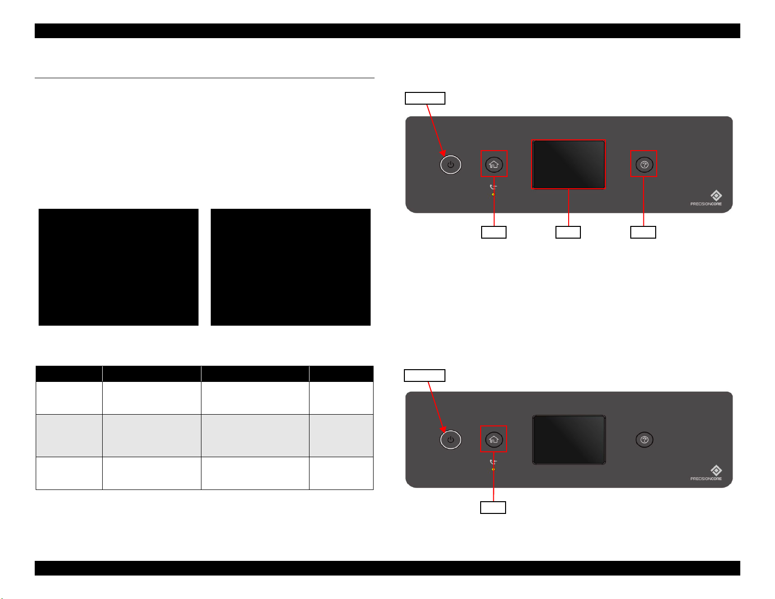
EPSON ET-4750/4760/3750/3760/3700/3710/2750/2760/2700/L6190/L6170/L6160/L4160/L4150/ST-4000/ST-3000/ST-2000 series Revision I
Maintenance SP Mode
Run:[Touch PNL] / Select:[HELP]
1.Printer Inspection Mode
2.Status Sheet Print Mode
3.Touch Screen Calibration
Maintenance SP Mode
Run:[OK] / Select:[UP][DOWN]
1.Printer Inspection Mode
2.Status Sheet Print Mode
Touch Panel 2.4 inch model LCD Model
SW1 SW2 SW3
Power SW
SW1
Power SW
2.4 Service Support Mode
Overview
Service support mode is a service dedicated special mode that can be started by
a special operation from LCD panel, and allows you to execute functions
including printer mode, service status sheet, and touch panel adjustment. ET2750/ET-2760/L4160/ST-2000 series are excluded from this mode because
they don't have LCD.
Structure of service support mode menu
Figure 2-2. Service support mode: top menu
2.4.1 Touch Panel 2.4 inch model
Figure 2-3. Panel operation in service support mode
(Touch Panel 2.4 inch model)
Service Support Mode startup and operating procedures
1. Press the [SW1] and [Power SW] button until the screen switches, starting
the printer.
Item Display Explanation When to use
Printer mode Printer Inspection Mode
Service status
sheet print (p.67)
Touch panel
adjustment
(p.171)
Status Sheet Print Mode
Touch Screen Calibration
Troubleshooting Service Support Mode 64
Allows you to perform
adjustment with the ADF/SCN
Unit removed.
In addition to the normal status
sheet information, you can check
information needed for
servicing.
Perform the home position
adjustment of the touch panel.
When repairing
Troubleshooting
When repairing
Figure 2-4. Service Support Mode startup and operating procedures
Confidential
Page 65

EPSON ET-4750/4760/3750/3760/3700/3710/2750/2760/2700/L6190/L6170/L6160/L4160/L4150/ST-4000/ST-3000/ST-2000 series Revision I
Power SW
SW1
SW2 SW3
UP:[Right]
SHIFT:[Left]/FIN:[Center]
*****_
OK
Power SW
2. Operate the Touch Panel, and enter the ID.
ID to enter: 61544
Operating procedure
1. Tap [SW3] until the value necessary for this digit is displayed.
2. Tap [SW1] to enter the value. The value will change to “*”, and
the cursor goes to the next digit.
3. Repeat steps 1 and 2 to enter the 5 digit ID.
4. When entry is completed, tap [SW2] to confirm.
2.4.2 LCD Model
Service Support Mode startup and operating procedures
1. Press the [SW1] and [Power SW] button until the screen switches, starting
the printer.
Figure 2-6. Service Support Mode startup and operating procedures
Figure 2-5. Service support mode operation method
Troubleshooting Service Support Mode 65
Confidential
Page 66

EPSON ET-4750/4760/3750/3760/3700/3710/2750/2760/2700/L6190/L6170/L6160/L4160/L4150/ST-4000/ST-3000/ST-2000 series Revision I
UP:[Right]
SHIFT:[Left]/FIN:[Center]
*****_
Input ID is not found!!
Please wait Poweroff...
2. Operate the Touch Panel, and enter the ID.
ID to enter: 61544
Operating procedure
1. Press [Up] or [Down] until the value necessary for this digit is
displayed.
2. Press [Right] to enter the value. The value will change to “*”, and
the cursor goes to the next digit.
3. Repeat steps 1 and 2 to enter the 5 digit ID.
It is not possible to return to the previous digit after
shifting digits. If you wish to correct the number of the
previous digit, proceed with the steps until after step 5
and then perform input again.
Please note that the execute button is not enabled until at
least two digits have been entered.
Solution if enter and execute the wrong ID
When a different mode starts:
If you enter the wrong ID and a different mode starts,
there is the possibility of changing important settings of
the unit, so press the power button to turn off the power
immediately and then perform the process again to enter
the correct ID number.
When non-existent ID number:
The following panel LCD display appears and the power
is turned off automatically.
Figure 2-7. Service support mode operation method
Troubleshooting Service Support Mode 66
Confidential
Page 67
EPSON ET-4750/4760/3750/3760/3700/3710/2750/2760/2700/L6190/L6170/L6160/L4160/L4150/ST-4000/ST-3000/ST-2000 series Revision I
2.4.3 Status Sheet Information
This section explains about each item printed on the status sheets.
The following status sheets can be printed from the printer.
Overview of Status Sheets
Printer Information Sheet : printer settings information
Supply Status Sheet : supported model numbers of consumables or periodic replacement
parts, and the total number of sheets fed into the printer.
Usage History Sheet : usage history such as the total number of printed pages per function.
Service Status Sheet : in addition to the information included in the above three sheets, information required for servicing is also provided.
However, the status sheet can be printed only in service support mode. (p.64)
Status Sheet Items
Printer information sheet (total pages: 2 sheets)
Item Explanation
Device ID Device ID (product name) is displayed.
Serial Number The serial number of the product is displayed.
MAC Address MAC address of the product is displayed.
Hardware Configuration
<Hardware> Memory Capacity Capacity of the memory inside the product is displayed.
Firmware Version of the firmware is displayed.
Main Firmware Version of the main firmware is displayed.
<Version>
Network Firmware Version of the NW firmware is displayed.
QPIT Version of the QPIT is displayed.
Troubleshooting Service Support Mode 67
Confidential
Page 68

EPSON ET-4750/4760/3750/3760/3700/3710/2750/2760/2700/L6190/L6170/L6160/L4160/L4150/ST-4000/ST-3000/ST-2000 series Revision I
Item Explanation
Basic settings
<Sound
settings>
Paper cassette
Paper
source
settings
Print settings
Language The current language setting is displayed.
Mute The setting of mute (on/off) is displayed.
Button Press
Error Notice
Receive Completion Notice
Normal
Sleep timer setting
Power Off Settings
Auto Error Solver Whether the auto error resolver options are enabled or not is displayed.
Ink Drying Time The Ink Drying Time when duplex printing is displayed.
PC connection via USB Whether the setting is enabled or not is displayed.
Paper cassette 1
MP tray
A4/Letter Auto Switching Whether the auto switching function is enabled or not is displayed.
Paper Size Notice Whether the setting is enabled or not is displayed.
Paper Type Notice Whether the setting is enabled or not is displayed.
Universal Print
Settings
Send Completion Notice
Print Completion Notice
Ring Tone
Receiver
Paper Size Paper size settings for each of the paper sources.
Paper Type Paper type settings for each of the paper sources.
Paper Size Paper size settings of the rear tray is displayed.
Paper Type Paper type settings of the rear tray is displayed.
Top Offset
Left Offset
Top Offset in Back
Left Offset in Back
Check Paper Width Whether the setting is enabled or not is displayed.
Skip Blank Page Whether the setting is enabled or not is displayed.
Sound level setting (0 to 10) is displayed.
Whether the sleep timer is enabled or not is displayed. When enabled, the time period before
the product enters sleep mode is also displayed.
Whether the auto power off setting is enabled or not is displayed. When enabled, the time
period before the printer automatically turns off is also displayed.
The offset setting (-30 to 30) is displayed.
Troubleshooting Service Support Mode 68
Confidential
Page 69

EPSON ET-4750/4760/3750/3760/3700/3710/2750/2760/2700/L6190/L6170/L6160/L4160/L4150/ST-4000/ST-3000/ST-2000 series Revision I
Item Explanation
Color The color setting (Color or Mono) is displayed.
File Format File format setting is displayed.
Scan area Original document size setting is displayed.
Remove shadow Whether the setting is enabled or not is displayed.
The frame width setting (0 to 40 mm/---(in case of the shadow remove setting is disabled)) is
displayed.
The center width setting (0 to 40 mm/---(in case of the shadow remove setting is disabled))
is displayed.
The erasing setting (left edge/right edge/top edge/bottom edge/--- (in case of the remove
punch holes setting is disabled)) is displayed.
The erasing amount (0 to 20 mm/--- (in case of the remove punch holes setting is disabled))
is displayed.
Scan
settings
Scan to Cloud
Surround
Center
Remove Punch Holes Whether the setting is enabled or not is displayed.
Erasing Position
Erase Amount
Orientation The document orientation setting (portrait or landscape) is displayed.
Document Type The quality setting (Text/Text & Image/Photo) is displayed.
Density The density setting (-4 to 4) is displayed.
Troubleshooting Service Support Mode 69
Confidential
Page 70
EPSON ET-4750/4760/3750/3760/3700/3710/2750/2760/2700/L6190/L6170/L6160/L4160/L4150/ST-4000/ST-3000/ST-2000 series Revision I
Supply Status Sheet (total pages: 1 sheet)
Item Explanation
Device ID Device ID (product name) is displayed.
Serial Number The serial number of the product is displayed.
MAC Address MAC address of the product is displayed.
Hardware Configuration
Ink Bottle
Supply Status
Maintenance Box Serial Number Manufacturer's serial number of the Maintenance Box is displayed.
<Hardware> Memory Capacity Capacity of the memory inside the product is displayed.
Firmware Version of the firmware is displayed.
Main Firmware Version of the main firmware is displayed.
<Version>
Black Serial Number Manufacturer's serial number of each of the ink bottle is displayed.
Cyan
Magenta
Yellow
Network Firmware Version of the NW firmware is displayed.
QPIT Version of the QPIT is displayed.
Serial Number Manufacturer's serial number of each of the ink bottle is displayed.
Serial Number Manufacturer's serial number of each of the ink bottle is displayed.
Serial Number Manufacturer's serial number of each of the ink bottle is displayed.
Troubleshooting Service Support Mode 70
Confidential
Page 71

EPSON ET-4750/4760/3750/3760/3700/3710/2750/2760/2700/L6190/L6170/L6160/L4160/L4150/ST-4000/ST-3000/ST-2000 series Revision I
Usage History Sheet (total pages: 2 sheets)
Item Explanation
Device ID Device ID (product name) is displayed.
Serial Number The serial number of the product is displayed.
MAC Address MAC address of the product is displayed.
Hardware Configuration
Usage History First Time Printing The date and time when the printer printed for the first time is displayed.
Number of Pages
<Hardware> Memory Capacity Capacity of the memory inside the product is displayed.
Firmware Version of the firmware is displayed.
Main Firmware Version of the main firmware is displayed.
<Version>
<Sorted by Function>
<Sorted by Paper
Size>
(1-sided/2-sided,
B&W/Color)
Network Firmware Version of the NW firmware is displayed.
QPIT Version of the QPIT is displayed.
Total Number of Pages The total number of printed pages is displayed.
Total Number of B&W Pages The total number of pages printed in monochrome is displayed.
Total Number of Color Pages The total number of pages printed in color is displayed.
Total Number of 2-Sided Printing Pages The total number of printed 2-sided pages is displayed.
Total Number of 1-Sided Printing Pages The total number of printed one-sided pages is displayed.
A3/Ledger
A4/Letter
A5
A6
B4/Legal
B5
Envelope
Others
The total number of printed pages per paper size is displayed.
Detailed count per function (one-sided/2-sided, monochrome/color) is also displayed for each
paper size.
Troubleshooting Service Support Mode 71
Confidential
Page 72
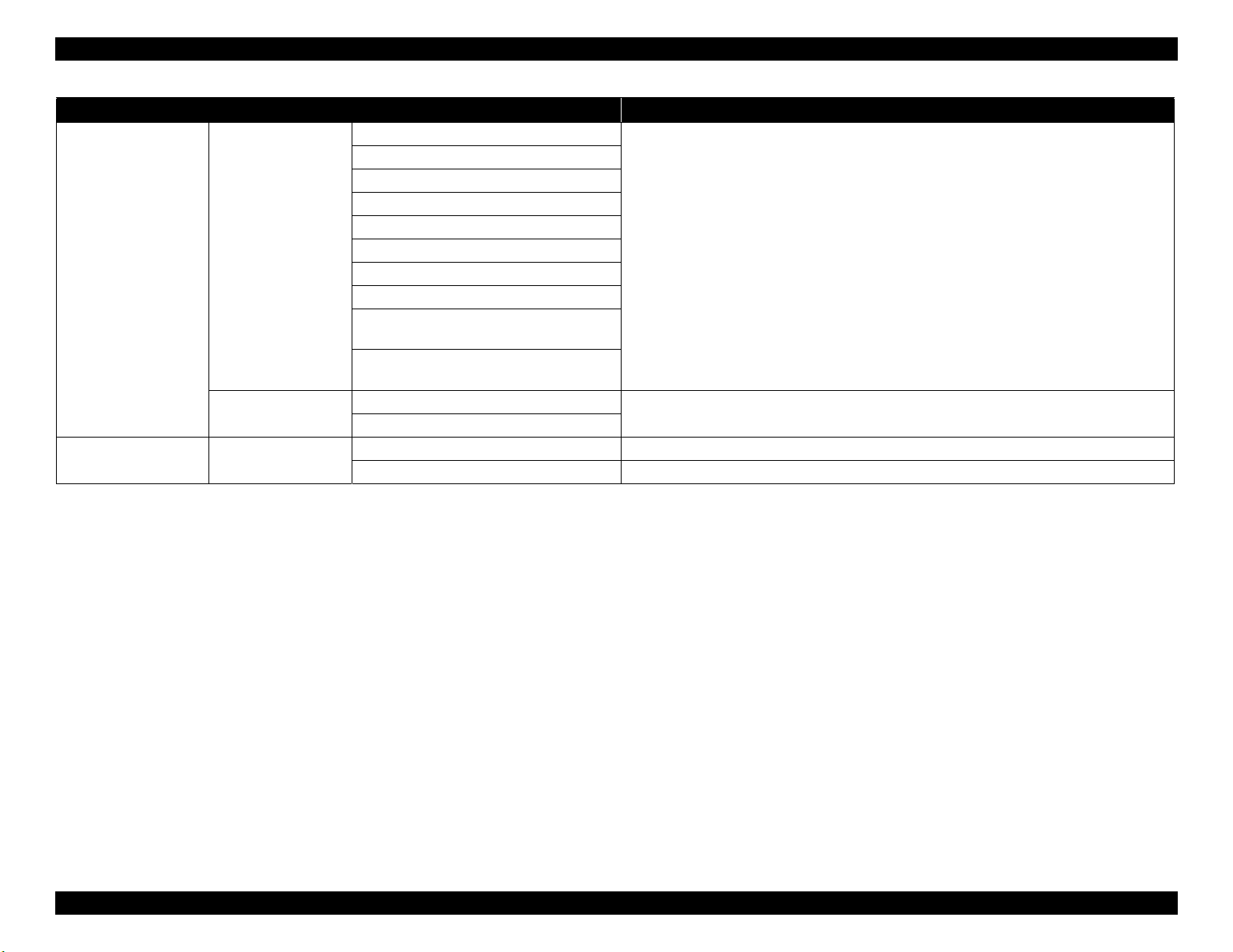
EPSON ET-4750/4760/3750/3760/3700/3710/2750/2760/2700/L6190/L6170/L6160/L4160/L4150/ST-4000/ST-3000/ST-2000 series Revision I
Item Explanation
B&W Copy
Color Copy
B&W Fax
Color Fax
B&W Scan
<Sorted by Usage>
Number of prints
<Sorted by Printer
Language>
Usage History Scanned page number
Color Scan
B&W Print from Computer or Mobile Device
Color Print from Computer or Mobile Device
B&W Print from Memory Device or Other
Functions
Color Print from Memory Device or Other
Functions
ESC/P-R
Others
B&W Scan Number of sheets scanned in monochrome.
Color Scan Number of sheets scanned in color.
The total number of printed pages for each of the purposes is displayed.
The version of each of the printer language is displayed.
Troubleshooting Service Support Mode 72
Confidential
Page 73

EPSON ET-4750/4760/3750/3760/3700/3710/2750/2760/2700/L6190/L6170/L6160/L4160/L4150/ST-4000/ST-3000/ST-2000 series Revision I
Service Status Sheet (total pages: 6 sheets)
Item Explanation
Device ID Device ID (product name) is displayed.
Serial Number The serial number of the product is displayed.
MAC Address MAC address of the product is displayed.
Hardware Configuration
Basic Settings
Paper
Source
Settings
Print Settings
Network Settings
Paper Cassette
<Hardware> Memory Capacity Capacity of the memory inside the product is displayed.
Firmware Version of the firmware is displayed.
Main Firmware Version of the main firmware is displayed.
<Version>
Sleep Timer
Power Off Settings
Ink Drying Time The Ink Drying Time when duplex printing is displayed.
Cassette 1/
Rear MP Tray
Universal Print
Settings
IP Address
Subnet Mask
Default Gateway
Primary DNS Server
Secondary DNS Server
DNS Domain Name
Proxy Server Settings
Proxy Server
Proxy Server Port Number
Network Firmware Version of the NW firmware is displayed.
QPIT Version of the QPIT is displayed.
Whether the sleep timer is enabled or not is displayed. When enabled, the time period
before the product enters sleep mode is also displayed.
Whether the auto power off setting is enabled or not is displayed. When enabled, the time
period before the printer automatically turns off is also displayed.
Paper Size Paper size settings for each of the paper sources.
Paper Type Paper type settings for each of the paper sources.
Top Offset
Left Offset
Top Offset in Back
Left Offset in Back
Check Paper Width Whether the setting is enabled or not is displayed.
Skip Blank Page Whether the setting is enabled or not is displayed.
The offset setting (-30 to 30) is displayed.
The network settings are displayed.
Troubleshooting Service Support Mode 73
Confidential
Page 74
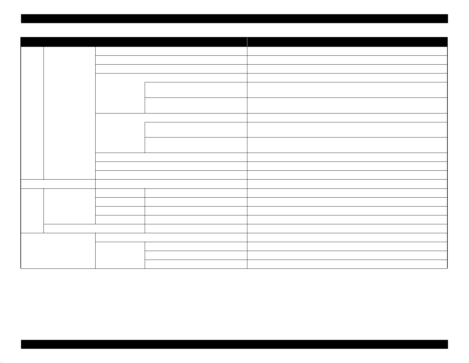
EPSON ET-4750/4760/3750/3760/3700/3710/2750/2760/2700/L6190/L6170/L6160/L4160/L4150/ST-4000/ST-3000/ST-2000 series Revision I
Item Explanation
Color Mode The color setting (Color or Mono) is displayed.
File Format File format setting is displayed.
Scan Area Original document size setting is displayed.
Remove Shadow (not provided for “Scan to Cloud”) Whether the setting is enabled or not is displayed.
Surround
Scan
settings
Option Settings Fax Function Whether the fax feature is enabled or not is displayed.
Supply
Status
Usage History
Scan to Cloud
Ink Bottle
Maintenance Box Serial Number Manufacturer's serial number of the Maintenance Box is displayed.
Remove Punch Holes Whether the setting is enabled or not is displayed.
Orientation (original) The document orientation setting (portrait or landscape) is displayed.
Document Type The quality setting (Text/Text & Image/Photo) is displayed.
Density The density setting (-4 to 4) is displayed.
Black Serial Number Manufacturer's serial number of each of the ink bottle is displayed.
Cyan
Magenta
Yellow
First Time Printing The data and time the printer printed for the first time are displayed.
<Sorted by
Function>
Center
Erasing Setting
Erase Amount
Serial Number Manufacturer's serial number of each of the ink bottle is displayed.
Serial Number Manufacturer's serial number of each of the ink bottle is displayed.
Serial Number Manufacturer's serial number of each of the ink bottle is displayed.
Total Number of Pages The total number of pages printed by the printer is displayed.
Total Number of B&W Pages The total number of pages printed in monochrome is displayed.
Total Number of Color Pages The total number of pages printed in color is displayed.
The frame width setting (0 to 40 mm/---(in case of the shadow remove setting is disabled))
is displayed.
The center width setting (0 to 40 mm/---(in case of the shadow remove setting is disabled))
is displayed.
The erasing setting (left edge/right edge/top edge/bottom edge/--- (in case of the remove
punch holes setting is disabled)) is displayed.
The erasing amount (0 to 20 mm/--- (in case of the remove punch holes setting is disabled))
is displayed.
Troubleshooting Service Support Mode 74
Confidential
Page 75

EPSON ET-4750/4760/3750/3760/3700/3710/2750/2760/2700/L6190/L6170/L6160/L4160/L4150/ST-4000/ST-3000/ST-2000 series Revision I
Item Explanation
A3/Ledger
A4/Letter
A5
A6
B4/Legal
B5
Envelope
Others
B&W Print from Computer or Mobile Device
Color Print from Computer or Mobile Device
B&W Copy
Color Copy
B&W Fax
Color Fax
B&W Print from Memory Device or Other
Functions
Color Print from Memory Device or Other
Functions
Document Table (Number of pages)
ADF (Number of pages)
ADF (Number of Fed Sheets) The total number of document sheets fed by the ADF is displayed.
Cassette 1/Rear MP Tray The total number of printed pages per paper source is displayed.
The total number of printed pages per paper size is displayed. Detailed count per function
(one-sided/2-sided, monochrome/color) is also displayed for each paper size.
The total number of printed pages for each of the purposes is displayed.
The total number of pages scanned on the scanner glass or in the ADF is displayed.
Status of the product (error occurring state) is displayed.
Usage History
Status
<Sorted by Paper
Size>
(1-sided/2-sided,
B&W/Color)
<Sorted by Usage>
Other The Cumulative number of paper jam The total number of times a paper jam error occurs is displayed.
Number of Sheets
Scanned
Number of Sheets
Loaded
Printer Error
Scanner Error
Fax Error
Network Error
Other Error
Troubleshooting Service Support Mode 75
Confidential
Page 76

DISASSEMBLY/ASSEMBLY
CHAPTER
3
Confidential
Page 77

EPSON ET-4750/4760/3750/3760/3700/3710/2750/2760/2700/L6190/L6170/L6160/L4160/L4150/ST-4000/ST-3000/ST-2000 series Revision I
3.1 Overview
This chapter describes procedures for disassembling the main parts/units of
ET-4750/ET-4760/L6190/ST-4000 series/ET-3750/ET-3760/L6170/ST-3000
series/ET-3700/ET-3710/L6160 series/ET-2750/ET-2760/L4160/ST-2000
series/ET-2700/L4150 series. Unless otherwise specified, disassembled parts/
units can be reassembled by reversing the disassembly procedure.
Disassembly/reassembly precautions and tips are give in
Major Components Disassembly/Assembly Procedure” (p113) and “3.4
Detailed Disassembly/Reassembly Procedure for each Part/Unit” (p142). See
the sections as necessary.
Make sure to read “ Safety Precautions” (p3) before starting work.
When you have to remove units or parts that are not described in this chapter,
see the exploded diagrams of SPI (Service Parts Information).
3.1.1 Tools
Use only specified tools to avoid damaging the printer.
Table 3-1. Tools
Name Availability EPSON Part Code
(+) Phillips screwdriver #1
(+) Phillips screwdriver #2 ✓ ---
Flathead screwdriver ✓ ---
Flathead Precision screwdriver #1 ✓ ---
Tweezers ✓ ---
Longnose pliers ✓ ---
Acetate tape --- 1003963
Note 1: “Availability” means that use of a commercially available one is permitted.
2: EPSON provides the tools listed with EPSON part code.
“3.3.4 Repairing
✓
1080530
3.1.2 Jigs
Table 3-2. Jigs
Name Quantity EPSON Part Code
Teflon tape (t = 0.08 mm) 1 1706715
Thickness gauge (1.37 mm) (for μTFP1S
head)
Thickness gauge (1.87 mm) (for μTFP1S
head)
Thickness gauge (1.45 mm) (for F2 head) 1
Thickness gauge (1.95 mm) (for F2 head) 1
Tube clip 4
Syringe 4
Case for extruding ink 4
1
1
Commercially available
Disassembly/Assembly Overview 77
Confidential
Page 78
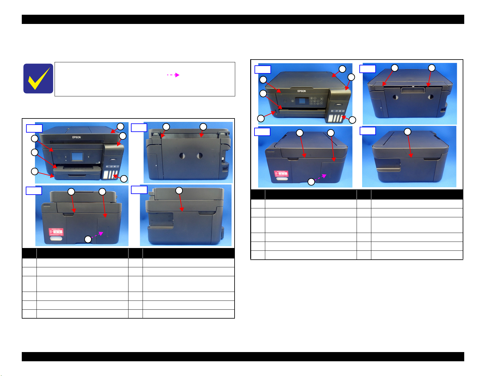
EPSON ET-4750/4760/3750/3760/3700/3710/2750/2760/2700/L6190/L6170/L6160/L4160/L4150/ST-4000/ST-3000/ST-2000 series Revision I
1
Front
2
3
4
5
6
Right
7 8
9
Left
10
Rear
1112
1
Front
2
3
4
5
6
Right
7 8
9
Left
10
Rear
1112
3.1.3 Locations of the Parts/Units
This section shows the locations of the main parts/units.
The parts/units which can not be seen in the following
pictures are indicated in dotted lines (
Exterior parts (ET-4750/ET-4760/L6190/ST-4000 series/ET-3750/ET-
3760/L6170/ST-3000 series)
No. Name No. Name
1 ADF/SCN Unit (p100) 7 Housing Right (p98)
2 Cover Tank (p98) 8 Cover Ink Eject (p98)
Ink Tank BK (p100)/
3
Ink Tank CL (x3) (p100)
4 Panel Unit (p98) 10 Housing Left (p98)
5 Stacker (p98) 11 Duplex Unit (p99)
6 Paper Cassette (p99) 12 Cover Hinge SCN (p98)
Figure 3-1. Exterior Parts (ET-4750/ET-4760/L6190/ST-4000 series/ET-
3750/ET-3760/L6170/ST-3000 series)
Maintenance Box (p98)
9
).
Exterior parts (ET-3700/ET-3710/L6160 series/ET-2750/ET-2760/L4160/
ST-2000 series)
No. Name No. Name
1 SCN Unit (p105) 7 Housing Right (p103)
2 Cover Tank (p103) 8 Cover Ink Eject (p103)
Ink Tank BK (p104)/
3
Ink Tank CL (x3) (p104)
4 Panel Unit (p103) 10 Housing Left (p103)
5 Stacker (p103) 11 Duplex Unit (p99)
6 Card Slot Assy (p104) 12 Cover Hinge SCN (p103)
Porous Pad Assy (p103)
9
Figure 3-2. Exterior Parts (ET-2750/ET-2760/L4160/ST-2000 series)
Disassembly/Assembly Overview 78
Confidential
Page 79

EPSON ET-4750/4760/3750/3760/3700/3710/2750/2760/2700/L6190/L6170/L6160/L4160/L4150/ST-4000/ST-3000/ST-2000 series Revision I
1
Front
2
3
4
5
Right
6
7
8
Left
9
Rear
10
1
Front
2
3
5
4
6
Right
7
10
Left
11
13
14
Rear
161517 18
Exterior parts (ET-2700/L4150 series)
No. Name No. Name
1 SCN Unit (p105) 6 Housing Right (p103)
2 Cover Tank (p103) 7 Cover Ink Eject (p103)
Ink Tank BK (p104)/
3
Ink Tank CL (x3) (p104)
Porous Pad Assy (p103)
8
4 Panel Unit (p103) 9 Housing Left (p103)
5 Stacker (p103) 10 Cover Hinge SCN (p103)
Figure 3-3. Exterior Parts (ET-2700/L4150 series)
Printer mechanism(ET-4750/ET-4760/L6190/ST-4000 series/ET-3750/
ET-3760/L6170/ST-3000 series
No. Name No. Name
Main Frame Assy (p101)
1
2 CR Scale & Spring (p100) 11 Fax Box (p98)
3 Cover CR (p99) 12 P/S Unit (p98)
4 Print Head (p99) 13 PF Encoder (p98)
5 Paper Guide Front Assy (p98) 14 PF Scale (p98)
6 Paper Guide Lower Porous Pad (p98) 15 CR Motor (p101)
7 SCN Hinge (p100) 16 Paper Guide Upper Right (p101)
8 CR Unit (p101) 17 Paper Guide Upper Left (p101)
9 Ink System (p100) 18 Main Board (p101)
/
ET-3700/ET-3710/L6160 series)
Ink Tank BK (p100)/
10
Ink Tank CL (x3) (p100)
Figure 3-4. Printer Mechanism
(ET-4750/ET-4760/L6190/ST-4000 series/ET-3750/ET-3760/L6170/ST-
3000 series/ET-3700/ET-3710/L6160 series)
Disassembly/Assembly Overview 79
Confidential
Page 80

EPSON ET-4750/4760/3750/3760/3700/3710/2750/2760/2700/L6190/L6170/L6160/L4160/L4150/ST-4000/ST-3000/ST-2000 series Revision I
1
Front
2
3
5
4
6
Right
7
8
10
Left
11
12
13
Rear
15
18
19
16
17
20
Printer mechanism (ET-2750/ET-2760/L4160/ST-2000 series/ET-2700/
Figure 3-5. Printer Mechanism
L4150 series)
No. Name No. Name
1 Frame ASF Rear Assy (p107) 11 P/S Unit (p103)
2 CR Scale & Spring (p104) 12 PF Encoder (p103)
3 Cover CR (p104) 13 PF Scale (p103)
4 Print Head (p104) 14 Card Slot Assy (p104)
5 Paper Guide Front Assy (p103) 15 CR Motor (p106)
Paper Guide Lower Porous Pad
6
(p103)
SCN Hinge (p105)
7
8 CR Unit (p106) 18 Paper Guide Upper Right (p107)
9 Ink System (p105) 19 Paper Guide Upper Left (p107)
10
Ink Tank BK (p104)/
Ink Tank CL (x3) (p104)
Shaft LD Rear Assy (p105)
16
Paper Set Detection Sensor Assy
17
(p105)
Main Board (p106)
20
Disassembly/Assembly Overview 80
Confidential
Page 81
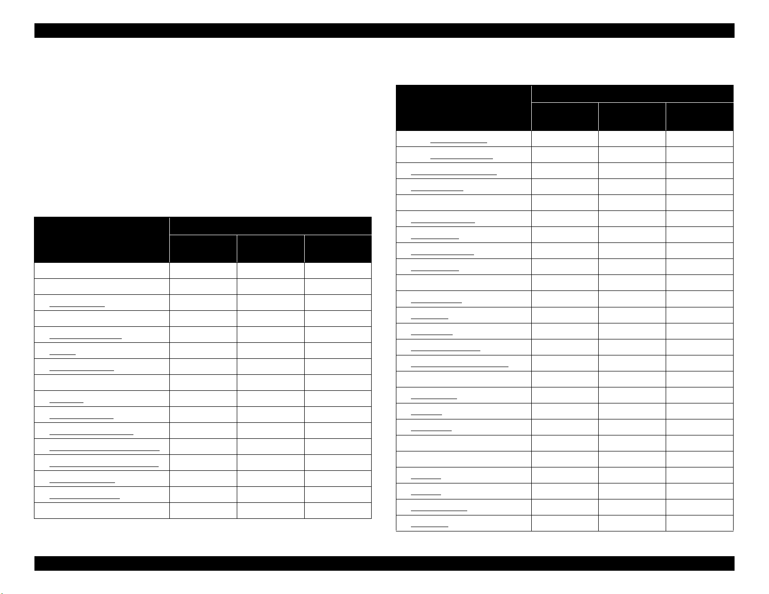
EPSON ET-4750/4760/3750/3760/3700/3710/2750/2760/2700/L6190/L6170/L6160/L4160/L4150/ST-4000/ST-3000/ST-2000 series Revision I
3.1.4 Standard Operation Time for Servicing the Product
The following are the standard operation time for servicing the product. This
standard operation time was determined based on the MTTR result measured
using the prototype of
2760/L4160/ST-2000 series
The underlined parts/units are supplied as After Service Parts.
ET-4750/ET-4760/L6190/ST-4000 series/ET-3750/ET-3760/L6170/ST-
3000 series/ET-3700/ET-3710/L6160 series
Table 3-3. Standard Operation Time (ET-4750/ET-4760/L6190/ST-4000 series/
ET-3750/ET-3760/L6170/ST-3000 series/ET-3700/ET-3710/L6160 series)
Parts/Unit
Duplex unit 0:04 3:54 3:58
Housing Upper Front 1:05 1:05
Cover Ink Eject 0:27 0:27
Maintenance Box 0:33 0:33
Pick up Roller Assy. 0:21 0:21
Stacker 0:12 0:12
Cover Cable Head 0:16 0:16
Cap Hinge Tank 0:04 0:04
Cap Tank 0:08 0:08
Cover Hinge SCN 0:14 0:14
Paper Guide Front Assy 0:49 1:40 2:29
Paper Guide Lower Porous Pad 0:58 0:02 1:00
ADF Document Support Cover 0:14 0:14
ADF Stacker Assy 0:27 0:27
PGU LD ADF Assy 0:28 0:28
Frame Upper ADF Assy 1:20 1:20
ET-4750/ET-4760/L6190/ST-4000 series/ET-2750/ET-
/ET-2750/ET-2760/L4160/ST-2000 series.
Time (in units of seconds)
Replacement
Adjustment/
inspection
Total
Table 3-3. Standard Operation Time (ET-4750/ET-4760/L6190/ST-4000 series/
ET-3750/ET-3760/L6170/ST-3000 series/ET-3700/ET-3710/L6160 series)
Time (in units of seconds)
Parts/Unit
Replacement
ADF PAD Assy 1:55 1:55
ADF PAD Spring 1:55 1:55
ADF Document Support 0:10 0:10
Document Mat 0:16 0:16
Cover CR 0:33 0:33
Adapter (CL) (x3) 1:37 1:37
Adapter (BK) 0:56 0:56
Sheet Guide Tube 1:26 1:26
Adapter Tube 3:12 3:12
Holder Board 2:15 2:15
Paper Cassette 0:11 2:14 2:25
Print Head 3:23 17:04 20:27
Cover Tank 1:11 1:11
Pressing Plate Tube 1:15 1:15
Guide Tube Supply Ink 2nd 3:08 3:08
Star Wheel Holder Assy 3:34 1:40 5:14
Housing Left 1:33 1:33
PF Scale 1:48 1:48
PF Encoder 2:19 2:19
Frame Main Support 2:30 2:30
Holder Core Fax 7:45 7:45
Fax Box 3:41 3:41
P/S Unit 3:04 1:18 4:22
ASF Bank Assy 5:07 2:14 7:21
Panel Unit 6:32 0:12 6:44
Adjustment/
inspection
Total
Disassembly/Assembly Overview 81
Confidential
Page 82

EPSON ET-4750/4760/3750/3760/3700/3710/2750/2760/2700/L6190/L6170/L6160/L4160/L4150/ST-4000/ST-3000/ST-2000 series Revision I
Table 3-3. Standard Operation Time (ET-4750/ET-4760/L6190/ST-4000 series/
ET-3750/ET-3760/L6170/ST-3000 series/ET-3700/ET-3710/L6160 series)
Time (in units of seconds)
Parts/Unit
Housing Right 2:04 2:04
Ink System 3:04 3:04
Holder Connector CSIC IS Assy 3:51 3:51
Holder Cable CSIC Ink Eject 3:51 3:51
Holder Housing Ink Eject
I/S transmission Gear 3:08 3:08
Ink Eject CSIC FFC 4:32 4:32
CR Scale & Spring 2:56 2:56
Holder Scale CR 3:16 3:16
Housing Front 3:38 3:38
Key Slot Assy 4:30 4:30
Tank Cover Sensor 5:02 5:02
Base Right Support 5:05 5:05
Tank Upper Porous Pad 5:09 5:09
Ink Tank BK 6:09 6:09
Ink Tank CL (x3) 7:49 7:49
Housing Upper Rear 2:34 2:34
SCN Hinge 3:55 3:55
Holder Damper SC 4:01 4:01
Rack Damper SC 4:01 4:01
SCN Lock Boss 4:02 4:02
ADF/SCN Unit 4:07 4:07
ADF Unit 4:52 4:52
Scanner Unit 4:52 0:49 5:41
Main Board 7:36 11:11 18:47
Replacement
4:09 4:09
Adjustment/
inspection
Total
Table 3-3. Standard Operation Time (ET-4750/ET-4760/L6190/ST-4000 series/
ET-3750/ET-3760/L6170/ST-3000 series/ET-3700/ET-3710/L6160 series)
Time (in units of seconds)
Parts/Unit
Cover Transistor 7:54 7:54
Heat Conduction Sheet 7:40 7:40
Wi-Fi Board 4:19 4:19
Paper Guide Dup Front 5:00 5:00
Paper Guide Upper Left 8:30 1:40 10:10
Paper Guide Upper Right 9:30 1:40 11:10
PE Sensor Assy 10:19 3:04 13:23
PE Sensor 10:45 3:04 13:49
PE Sensor Holder 10:45 10:45
PF Roller 11:25 2:01 13:26
Ink Eject FFC Plate 5:25 5:25
CR Driven Pulley 15:11 15:11
Main Frame Assy 16:14 8:56 25:10
CR Motor 17:01 3:25 20:26
Holder Cam Assy 16:47 16:47
Slider Trans & Spring 16:26 16:26
Spur Gear 17.6 16:18 16:18
Compression Spring
Transmission
CR Unit 17:31 6:28 23:59
PW Sensor 17:59 2:34 20:33
CR Encoder 18:10 18:10
CR Timing Belt 17:44 17:44
Head FFC 18:01 18:01
Head Grounding Plate 18:03 2:14 20:17
Replacement
16:18 16:18
Adjustment/
inspection
Total
Disassembly/Assembly Overview 82
Confidential
Page 83

EPSON ET-4750/4760/3750/3760/3700/3710/2750/2760/2700/L6190/L6170/L6160/L4160/L4150/ST-4000/ST-3000/ST-2000 series Revision I
Table 3-3. Standard Operation Time (ET-4750/ET-4760/L6190/ST-4000 series/
ET-3750/ET-3760/L6170/ST-3000 series/ET-3700/ET-3710/L6160 series)
Time (in units of seconds)
Parts/Unit
Main Frame 18:03 18:03
Frame Base Assy 16:14 16:14
Cover Porous Pad Rear 16:20 16:20
Paper Guide Lower Porous
Pad D
Porous Pad Frame Cover 17:02 17:02
Paper Guide Lower Porous
Pad B & C
EJ Roller Assy 17:12 1:40 18:52
PF Motor Assy 18:49 0:13 19:02
Frame Center Support 18:13 18:13
Paper Guide Lower Porous
Pad Bend
Center Support 18:13 18:13
Square Nut 16:21 16:21
Replacement
16:24 0:02 16:26
17:06 0:02 17:08
18:21 18:21
Adjustment/
inspection
Total
ET-2750/ET-2760/L4160/ST-2000 series
Table 3-4. Standard Operation Time (ET-2750/ET-2760/L4160/ST-2000 series)
Time
Parts/Unit
Replacement
Duplex unit 0:04 3:47 3:51
Housing Upper Front 1:05 1:05
Cover Ink Eject 0:26 0:26
Porous Pad Assy 0:48 0:48
Stacker 0:12 0:12
Cover Cable Head 0:16 0:16
Cap Hinge Tank 0:04 0:04
Cap Tank 0:08 0:08
Cover Hinge SCN 0:14 0:14
Paper Guide Front Assy 0:49 1:51 2:40
Paper Guide Lower Porous Pad 0:58 0:02 1:00
Cover Document Assy 0:06 0:06
Document Mat 0:16 0:16
Cover Rear ASF Assy 0:04 0:04
Cover CR 0:33 0:33
Adapter (CL) (x3) 1:37 1:37
Adapter (BK) 0:56 0:56
Sheet Guide Tube 1:26 1:26
Adapter Tube 3:12 3:12
Holder Board 2:15 2:15
Print Head 3:23 16:49 20:12
Housing Right 2:19 2:19
Cover Tank 1:11 1:11
Pressing Plate Tube 1:15 1:15
Adjustment/
inspection
Total
Disassembly/Assembly Overview 83
Confidential
Page 84

EPSON ET-4750/4760/3750/3760/3700/3710/2750/2760/2700/L6190/L6170/L6160/L4160/L4150/ST-4000/ST-3000/ST-2000 series Revision I
Table 3-4. Standard Operation Time (ET-2750/ET-2760/L4160/ST-2000 series)
Time
Parts/Unit
Guide Tube Supply Ink 2nd
Star Wheel Holder Assy 3:34 1:51 5:25
Housing Left 1:33 1:33
PF Scale 1:48 1:48
PF Encoder 2:19 2:19
Frame Main Support 2:30 2:30
P/S Unit 2:55 1:25 4:20
Holder Core Card Slot 6:59 6:59
CR Scale & Spring 3:11 3:11
Holder Scale CR 3:31 3:31
Ink System 3:19 3:19
I/S transmission Gear 3:23 3:23
Panel Unit 4:04 4:04
Housing Front 4:38 4:38
Card Slot Assy 5:47 5:47
Key Slot Assy 5:30 5:30
Base Right Support 6:05 6:05
Tank Upper Porous Pad 6:09 6:09
Ink Tank BK 7:09 7:09
Ink Tank CL (x3) 8:49 8:49
Housing Upper Rear 3:17 3:17
SCN Hinge 4:38 4:38
Holder Damper SC 4:44 4:44
Rack Damper SC 4:44 4:44
SCN Lock Boss 4:45 4:45
Replacement
3:08 3:08
Adjustment/
inspection
Total
Table 3-4. Standard Operation Time (ET-2750/ET-2760/L4160/ST-2000 series)
Time
Parts/Unit
SCN Unit 4:45 0:49 5:34
Main Board 8:14 11:35 19:49
Cover Transistor 8:32 8:32
Heat Conduction Sheet 8:18 8:18
Wi-Fi Board 4:57 4:57
Paper Set Detection Sensor Assy 5:34 3:47 9:21
Paper Set Detection Sensor
Board
Paper Set Detection Sensor
Lever
Paper Set Detection Sensor
FFC
Sheet Stopper 5:45 5:45
Shaft LD Rear Assy 6:28 3:47 10:15
Holder Clutch Assy 6:37 6:37
Clutch Assy 6:05 6:05
Spur Gear Clutch 45.6 6:10 6:10
Extension Spring 0.137 5:51 5:51
Paper Guide Upper Right Spring 7:26 7:26
Frame ASF Rear Assy 7:37 3:47 11:24
PE Sensor Assy 8:26 2:14 10:40
PE Sensor 8:52 2:14 11:06
PE Sensor Holder 8:52 8:52
Paper Guide Upper Left Spring 9:43 9:43
Paper Guide Upper Left 13:13 1:51 15:04
Paper Guide Upper Right 15:11 1:51 17:02
Replacement
6:07 6:07
5:59 5:59
6:04 6:04
Adjustment/
inspection
Total
Disassembly/Assembly Overview 84
Confidential
Page 85

EPSON ET-4750/4760/3750/3760/3700/3710/2750/2760/2700/L6190/L6170/L6160/L4160/L4150/ST-4000/ST-3000/ST-2000 series Revision I
Table 3-4. Standard Operation Time (ET-2750/ET-2760/L4160/ST-2000 series)
Time
Parts/Unit
PF Roller 15:08 2:10 17:18
CR Driven Pully 14:48 14:48
Main Frame Assy 15:51 8:18 24:09
CR Motor 16:38 3:28 20:06
Holder Cam Assy 16:24 16:24
Slider Trans & Spring 16:03 16:03
Spur Gear 17.6 15:55 15:55
Compression Spring
Transmission
CR Unit 17:08 6:09 23:17
PW Sensor 17:36 2:14 19:50
CR Encoder 17:47 17:47
CR Timing Belt 17:21 17:21
Head FFC 17:38 17:38
Head Grounding Plate 17:40 1:56 19:36
Main Frame 17:40 17:40
Frame Base Assy 15:51 15:51
Frame Cover Porous Pad
EJ Roller Assy 16:49 1:51 18:40
Frame Ground 22:10 22:10
PF Motor Assy 22:50 0:18 23:08
Change Lever 16:04 16:04
Square Nut 15:58 15:58
Replacement
15:59 15:59
16:39 16:39
Adjustment/
inspection
Total
ET-2700/L4150 series
Table 3-5. Standard Operation Time (ET-2700/L4150 series)
Time
Parts/Unit
Replacement
Housing Upper Front 0:30 0:30
Cover Ink Eject 0:26 0:26
Porous Pad Assy 0:48 0:48
Stacker 0:12 0:12
Pick up Roller Assy 0:21 0:21
Cover Cable Head 0:16 0:16
Cap Hinge Tank 0:04 0:04
Cap Tank 0:08 0:08
Cover Hinge SCN 0:14 0:14
Paper Guide Front Assy 0:49 1:51 2:40
Paper Guide Lower Porous Pad 0:58 0:02 1:00
Cover Document Assy 0:06 0:06
Document Mat 0:16 0:16
Cover Rear ASF Assy 0:04 0:04
Cover CR 0:33 0:33
Adapter (CL) (x3) 1:37 1:37
Adapter (BK) 0:56 0:56
Sheet Guide Tube 1:26 1:26
Adapter Tube 3:12 3:12
Holder Board 2:15 2:15
Print Head 3:23 16:49 20:12
Housing Right 1:44 1:44
Cover Tank 0:36 0:36
Pressing Plate Tube 0:40 0:40
Adjustment/
inspection
Total
Disassembly/Assembly Overview 85
Confidential
Page 86

EPSON ET-4750/4760/3750/3760/3700/3710/2750/2760/2700/L6190/L6170/L6160/L4160/L4150/ST-4000/ST-3000/ST-2000 series Revision I
Table 3-5. Standard Operation Time (ET-2700/L4150 series)
Time
Parts/Unit
Guide Tube Supply Ink 2nd
Star Wheel Holder Assy 2:59 1:51 4:50
Housing Left 0:58 0:58
PF Scale 1:13 1:13
PF Encoder 1:44 1:44
Frame Main Support 1:55 1:55
P/S Unit 2:20 1:25 3:45
Holder Core Card Slot 6:24 6:24
CR Scale & Spring 2:36 2:36
Holder Scale CR 2:56 2:56
Ink System 2:44 2:44
I/S transmission Gear 2:48 2:48
Housing Front 4:37 4:37
Panel Unit 4:58 4:58
Key Slot Assy 5:29 5:29
Base Right Support 6:04 6:04
Tank Upper Porous Pad 6:08 6:08
Ink Tank BK 7:08 7:08
Ink Tank CL (x3) 8:48 8:48
Housing Upper Rear 2:42 2:42
Housing Rear Assy. 2:45 2:45
Holder Lever MA 2:58 2:58
Paper Support 2:58 2:58
SCN Hinge 4:03 4:03
Holder Damper SC 4:09 4:09
Replacement
2:33 2:33
Adjustment/
inspection
Total
Table 3-5. Standard Operation Time (ET-2700/L4150 series)
Time
Parts/Unit
Rack Damper SC 4:09 4:09
SCN Lock Boss 4:10 4:10
SCN Unit 4:10 0:49 4:59
Main Board 7:39 11:35 19:14
Cover Transistor 7:57 7:57
Heat Conduction Sheet 7:43 7:43
Wi-Fi Board 4:22 4:22
Paper Set Detection Sensor Assy 4:59 3:47 8:46
Paper Set Detection Sensor
Lever
Sheet Stopper 5:10 5:10
Shaft LD Rear Assy 5:53 3:47 9:40
Holder Clutch Assy 6:02 6:02
Clutch Assy 5:30 5:30
Spur Gear Clutch 45.6 5:35 5:35
Extension Spring 0.137 5:16 5:16
Paper Guide Upper Right Spring 6:51 6:51
Frame ASF Rear Assy 7:02 3:47 10:49
PE Sensor Assy 7:51 2:14 10:05
PE Sensor 8:17 2:14 10:31
PE Sensor Holder 8:17 8:17
Paper Guide Upper Left Spring 9:08 9:08
Paper Guide Upper Left 12:38 1:51 14:29
Paper Guide Upper Right 14:36 1:51 16:27
PF Roller 14:33 2:10 16:43
CR Driven Pully 14:13 14:13
Replacement
5:24 5:24
Adjustment/
inspection
Total
Disassembly/Assembly Overview 86
Confidential
Page 87

EPSON ET-4750/4760/3750/3760/3700/3710/2750/2760/2700/L6190/L6170/L6160/L4160/L4150/ST-4000/ST-3000/ST-2000 series Revision I
Air hole
breathable film
Table 3-5. Standard Operation Time (ET-2700/L4150 series)
Time
Parts/Unit
Main Frame Assy 15:16 8:18 23:34
CR Motor 16:03 3:28 19:31
Holder Cam Assy 15:49 15:49
Slider Trans & Spring 15:28 15:28
Spur Gear 17.6 15:20 15:20
Compression Spring
Transmission
CR Unit 16:33 6:09 22:42
PW Sensor 17:01 2:14 19:15
CR Encoder 17:12 17:12
CR Timing Belt 16:46 16:46
Head FFC 17:03 17:03
Head Grounding Plate 17:05 1:56 19:01
Main Frame 17:05 17:05
Frame Base Assy 15:16 15:16
Frame Cover Porous Pad
EJ Roller Assy 16:14 1:51 18:05
Frame Ground 21:35 21:35
PF Motor Assy 22:15 0:18 22:33
Change Lever 15:29 15:29
Square Nut 15:23 15:23
Replacement
15:24 15:24
16:04 16:04
Adjustment/
inspection
Total
3.1.5 Checks and Precautions before Disassembling
3.1.5.1 Factors which Affect the Print Quality
WETTING OF VENTILATION FILM
The film under sealing film attached on the Ink Tank is breathable film. The air
in the ink tank is released to outside through this film and then the air hole to
keep ink supply to the Print Head stable. If the film gets wet with ink, the air in
the tank is not properly released outside and may cause degradation in print
quality.
Figure 3-6. Breathable film/air hole
Disassembly/Assembly Overview 87
Confidential
Page 88

EPSON ET-4750/4760/3750/3760/3700/3710/2750/2760/2700/L6190/L6170/L6160/L4160/L4150/ST-4000/ST-3000/ST-2000 series Revision I
breathable film
Hard to notice by seeing the surface Cyan ink soiled
Determining whether the breathable film is wet or not
When the breathable film is wet, tank replacement is
necessary. Because it is hard to notice that the film is wet
just by visually checking its surface, determine that
according to whether the ink has reached to a certain
portion of the air chamber.
When the ink has reached the red squared part of the air chamber shown below,
breathable film is probably wet. In this case, replace the Ink Tank.
DIFFERENT TYPE OF INK MIXED IN INK TANK
From the specification of the CISS models, different type/color of ink may get
mixed by mistaking the ink injection place. If there is a problem in printing
result, the cause may be ink mixture, refer the following to handle the problem.
Mixture of different type/color of the ink is state as follows.
Different type: pigment black ink and dye color ink mixed
The head nozzles may get clogged with solidified ink
particles.
Different color: dye color inks mixed.
A print quality problem will occur, but ink
solidification will not occur.
It is recommended to remove the user's Maintenance Box/
Porous Pad Assy when performing the ink tube refresh
because it consumes a lot of ink.
The powerful cleaning in the adjustment program
corresponds to the ink tube refresh. Select “not to count up
the waste ink counter” to prevent a mismatch between the
program's waste ink counter and the counter of the user's
Porous Pad Assy.*
Note "*" : If you do not select the option, the waste ink counter will count up during
the ink tube refresh.
Figure 3-7. Wetting of breathable film
Disassembly/Assembly Overview 88
Confidential
Page 89
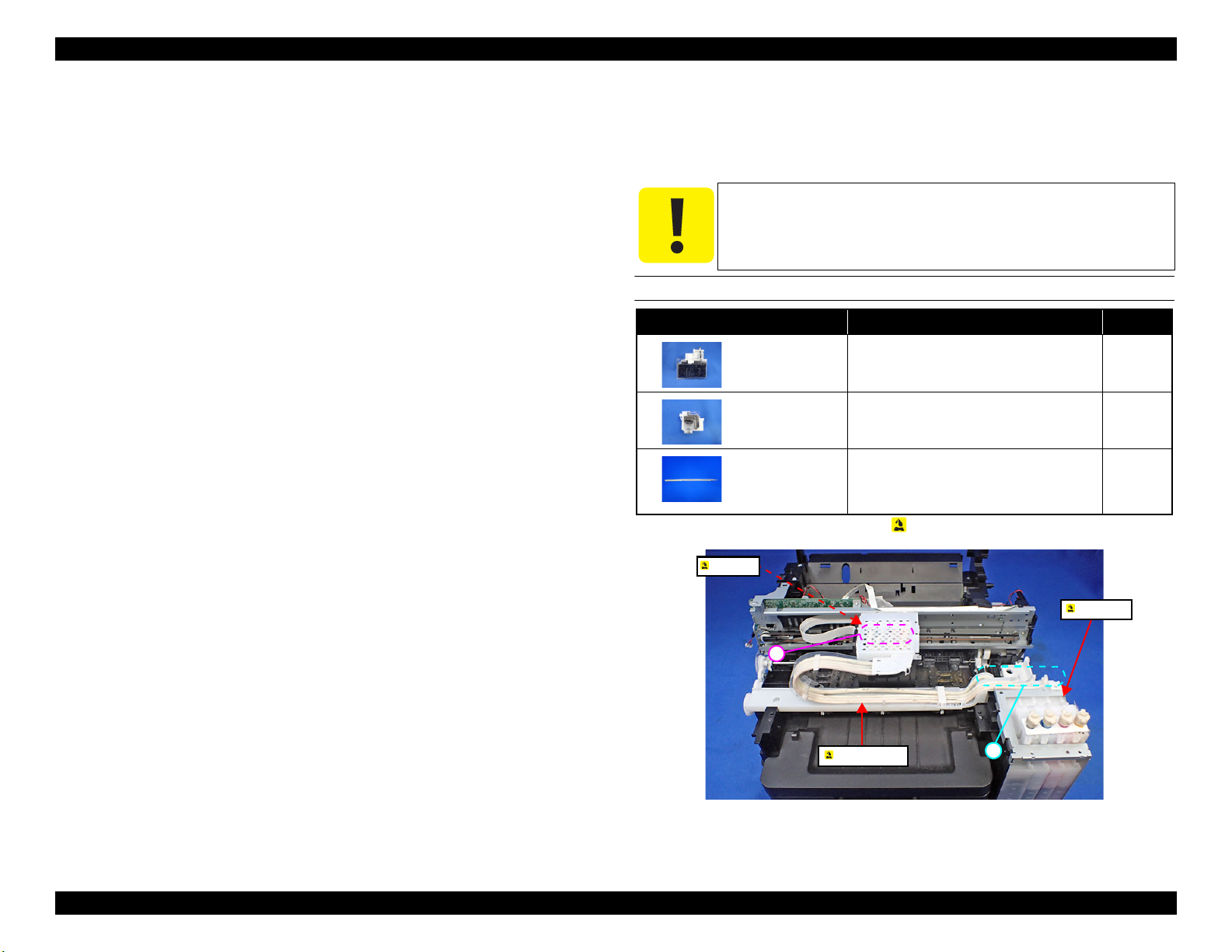
EPSON ET-4750/4760/3750/3760/3700/3710/2750/2760/2700/L6190/L6170/L6160/L4160/L4150/ST-4000/ST-3000/ST-2000 series Revision I
B
A
Ink Tank
Adapter tube
Adapter
How to deal with mixture of different type/color ink
When the ink got mixed, it is necessary to clean the CISS mechanism (from the
Ink Tank to the Adapter).
There are the following two methods.
Replace the CISS mechanism
1. Replace the CISS mechanism
2. Remove the user’s Maintenance Box/Porous Pad Assy and attach the
Porous Pad for jigs.
3. To clean the head, inject CR02 into the tank.
4. Start “head cleaning” or “ink refill”, select “not to count up the waste
ink counter”, then perform the ink tube refresh.
4760/L6190/ST-4000 series
/ET-3750/ET-3760/L6170/ST-3000 series/
*For ET-4750/ET-
ET-3700/ET-3710/L6160 series, cleaning without counting up the
waste ink counter is available only in the service support mode.
5. After each ink tube refresh, print a page to see if a blank page is printed
(printed only with CR02). Repeat ink tube refresh until you get a blank
page print.
6. Eject CR02 from the Ink Tank and fill the tank with new ink.
7. Perform the ink tube refresh again, and then check that the print quality
has been recovered.
Cleaning inside the ink path (reusing the CISS mechanism)
1. Eject the ink inside the Ink Tank/ink tube.
2. Inject CR02 into the Tank to clean the head and the CISS mechanism.
3. Start the adjustment program, select “not to count up the waste ink
counter”, then repeat ink tube cleaning.
4. Start “head cleaning” or “ink refill”, select “not to count up the waste
ink counter”, then repeat the ink tube refresh.*
L6190/ST-4000 series
3700/ET-3710/L6160 series
/ET-3750/ET-3760/L6170/ST-3000 series/ET-
, cleaning without counting up the waste
ink counter is available only in the service support mode.
For ET-4750/ET-4760/
5. Eject CR02 from the Ink Tank and fill the tank with new ink.
6. Perform the ink tube refresh again, and then check that the print quality
has been recovered.
3.1.5.2 Minimizing Ink Leakage during Disassembly for Your Safety
Ink leakage may occur when removing ink-related parts from the printer.
This section describes the parts that may cause ink leakage and how to prevent
or minimize the leakage.
When the printer get soiled by the ink leakage, wipe the ink
with a cloth wet with CR02. Do not use alcohol to the parts
that touch the ink such as tube connecting part and adapter.
THE PARTS THAT MAY CAUSE INK LEAKAGE WHEN REMOVING
Parts name* When ink leakage may occur Location
Ink Tank Removing the adapter tube from the Ink
Tank.
Adapter Removing the adapter tube from the
adapter.
Adapter tube
Note "*" : These parts are indicated with the icon in disassembly/reassembly flowchart. (see
" 3.3.3 Disassembly Flowchart (p97) ")
• Removing the adapter tube from the Ink
Tank.
• Removing the adapter tube from the
adapter.
Figure 3-8. The Parts That May Cause Ink Leakage
A
B
A, B
Disassembly/Assembly Overview 89
Confidential
Page 90
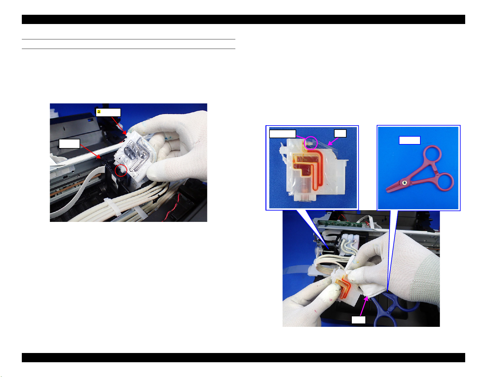
EPSON ET-4750/4760/3750/3760/3700/3710/2750/2760/2700/L6190/L6170/L6160/L4160/L4150/ST-4000/ST-3000/ST-2000 series Revision I
Carriage
Adapter
Film
Connector
Cloth
Tube clip
HOW TO MINIMIZE THE INK LEAKAGE
Before disassembling, check the following methods.
Removing adapter from the carriage
Before disconnecting the joint parts of the ink path, make sure to remove the
Adapter from the Carriage.
Disconnecting the Adapter and the Adapter Tube
Be careful not to press the film portion of the Adapter since doing so may cause
ink to leak. Hold the Adapter by its plastic portion when disconnecting the
Adapter tube.
In addition, before disconnecting the tube, pinch it with the tube clip and cover
the tube end with a cloth to minimize ink leakage.
To ol s n e ed ed
Tube clip
Cloth
Figure 3-9. Ink leakage from adapter
Figure 3-10. Disconnecting adapter and adapter tube (1)
Disassembly/Assembly Overview 90
Confidential
Page 91
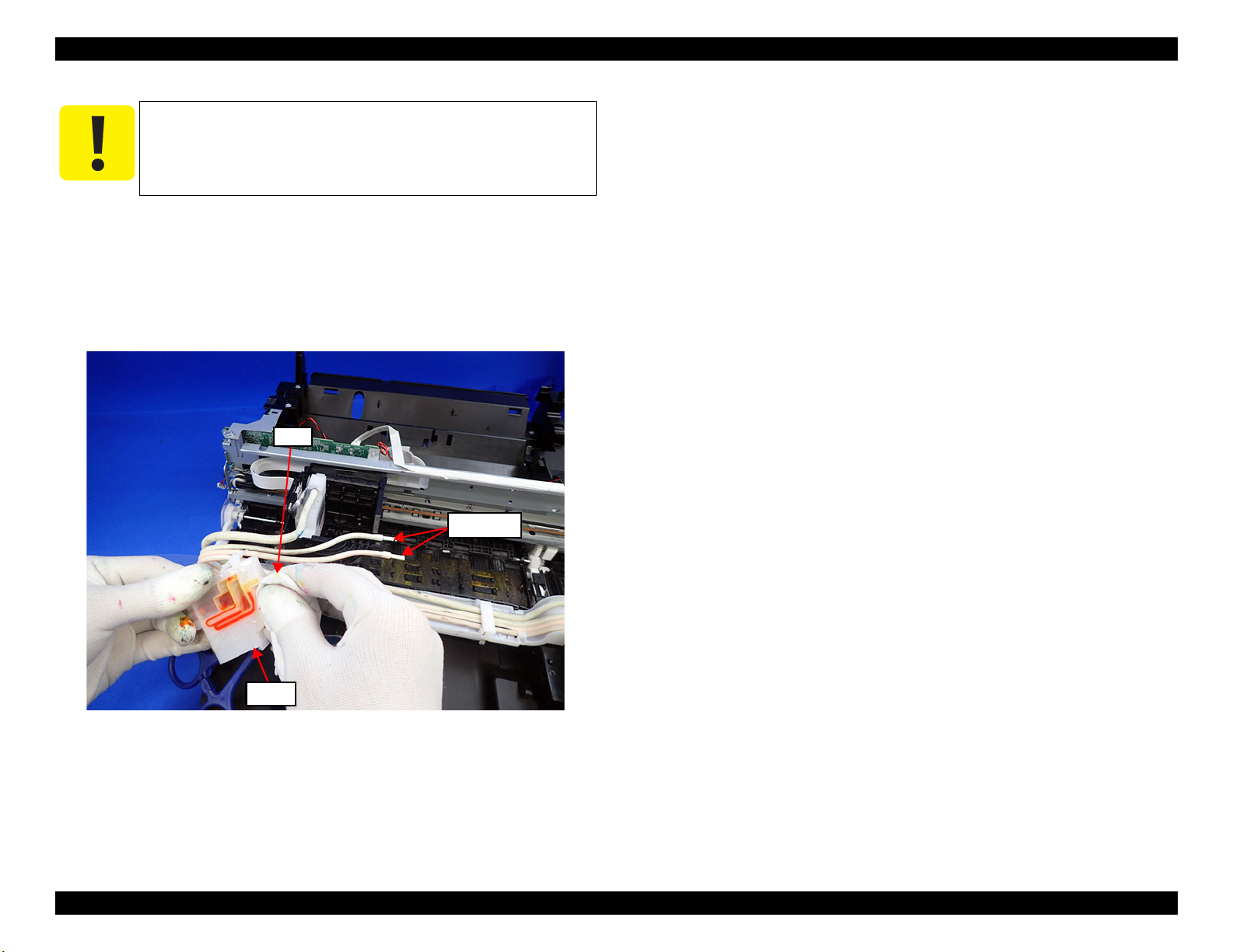
EPSON ET-4750/4760/3750/3760/3700/3710/2750/2760/2700/L6190/L6170/L6160/L4160/L4150/ST-4000/ST-3000/ST-2000 series Revision I
Adapter
Cotton swab
Cloth
When removing the adapter tube from the adapter in the
procedure given below, ink may leak from the adapter tube.
Perform disconnection off the printer and be careful not to
soil printer and things around.
1. Pinch the adapter tube with a tube clip and remove it from the adapter.
2. To prevent ink leakage, plug a cotton swab into the tip of the adapter tube.
3. Remove the tube clip from the adapter tube.
4. Repeat Step 1 to Step 3 until all four adapter tubes are removed.
Figure 3-11. Disconnecting adapter and adapter tube (2)
Disassembly/Assembly Overview 91
Confidential
Page 92

EPSON ET-4750/4760/3750/3760/3700/3710/2750/2760/2700/L6190/L6170/L6160/L4160/L4150/ST-4000/ST-3000/ST-2000 series Revision I
Cap Hinge Tank
Syringe
Adapter
3.1.5.3 Ink Discharging Procedure
Before removing the Ink Tank, discharge the ink in the procedure given below
if necessary.
1. Disconnect the adapter from the printhead. (p 90)
2. Connect any syringe (standard: tip of the syringe = Φ3.2mm, capacity = 50
mL) to the disconnected adapter.
3. Open the Cap Hinge Tank.
4. Suck out the ink inside the Ink Tank with the connected syringe.
Figure 3-13. Ink discharging (2)
5. Repeat Step 1 to Step 4 for each color.
Figure 3-12. Ink discharging (1)
Disassembly/Assembly Overview 92
Confidential
Page 93

EPSON ET-4750/4760/3750/3760/3700/3710/2750/2760/2700/L6190/L6170/L6160/L4160/L4150/ST-4000/ST-3000/ST-2000 series Revision I
2.
Housing Upper Rear
3.
Main Frame Assy
Main Board
Holder Core Fax
2.
2.
3.
2.
4.2.
3.2 Common Cautions on Disassembly/Reassembly
This section describes common cautions when disassembling/reassembling the
product.
Before disassembling/reassembling a printer including this product, be sure to
Safety Precautions(P3) and this section.
read
Item Content Photo/Illustration
When
handling
parts
When
reassembling
When
applying
grease
External
parts
Moving
parts
1. When handling new parts for
replacement, take care not to
contaminate or damage them.
2. Take care not to damage the
FFCs/cables/Ink tube if there
is a possibility of coming into
contact with them.
3. When reassembling the
product, take care not to let
components of the unit come
off.
Take care not to damage them
when securing them by
tightening screws.
Do not lubricate any part other
than those specified. If grease is
applied on such a part, wipe it off
completely.
Confirm visually that there are
no scratches, dirt, and gaps.
After reassembling, confirm that
there are no abnormal noises and
they work smoothly.
---
---
---
Item Content Photo/Illustration
Timing belts 1. Take care not to break them.
2. Confirm that it is installed
properly onto the transmissive
sections of the pinion gear/
driven roller.
Motors Take care not to damage the
pinion gears.
Sensors 1. Take care not to touch the
detector sections.
2. As for the encoder Sensor
used with a circular scale, the
photo sensor section should be
set over the encoded area of
the circular scale.
3. Take care not to get injured by
the sharp ends of the board
terminal on the back of the
circuit boards when handling
the sensors or the peripheral
parts.
Scales 1. Take care not to touch the
encoded area.
2. Install it with the black section
up. (CR Scale only)
3. Wipe the scale with alcohol
before installing. (CR Scale
only)
4. Confirm that they do not touch
the photo sensors after
installation.
---
Disassembly/Assembly Common Cautions on Disassembly/Reassembly 93
Confidential
Page 94
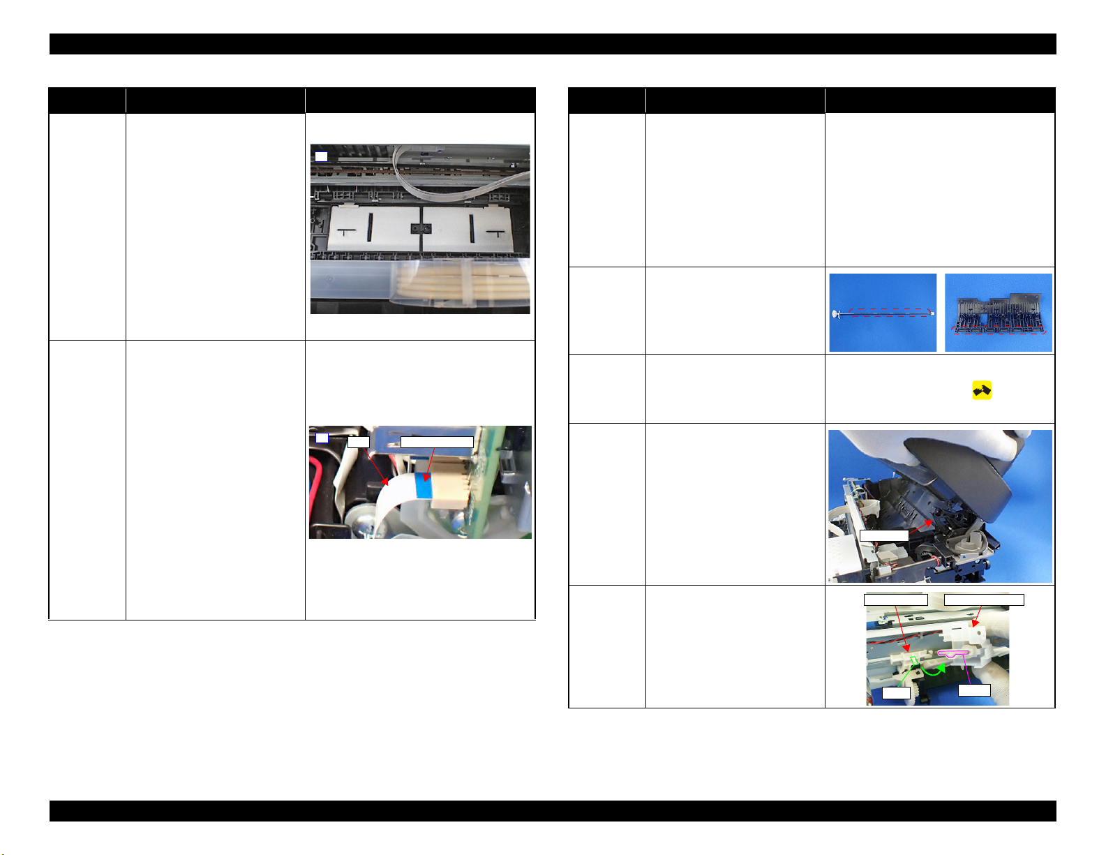
EPSON ET-4750/4760/3750/3760/3700/3710/2750/2760/2700/L6190/L6170/L6160/L4160/L4150/ST-4000/ST-3000/ST-2000 series Revision I
2.
FFC
strengthen plate
4.
SCN Hinge
Holder Cam AssySlider Trans
Dowel
groove
Item Content Photo/Illustration
Waste ink
pads
1. Take care not to stain your
hands with the waste ink
soaked in the ink pads. If ink
comes into contact with your
hands, wash it off with water
immediately.
2. Take care not to stain the
printer's parts with the waste
ink soaked in the ink pads. If
ink comes into contact with
the parts, wash it off.
(Especially, pay attention to
Paper Guide Front/Lower
Porous Pad)
FFCs 1. Be sure to insert them to their
connectors on the boards as
far as they will go without any
loose connection such as a
half-way or slant connection.
2. Route them along their routing
paths.
3. If the double-sided tape that
secures the FFCs is not strong
enough to secure them, make
sure to replace the tape and
secure the FFCs firmly.
4. When connecting to the
connector, be careful not to
break the strengthen plate on
the backside of the terminal of
the FFC.
Item Content Photo/Illustration
Gears When installing gears, pay
attention to the following:
• The gear section should not be
damaged.
• No foreign material is
---
attached.
• No grease is attached on any
parts other than those
specified.
Paper feed
rollers
One Time
parts
Do not touch rollers for paper
feeding when handling them.
After removing One Time parts
specified in this manual, do not
reuse them, but be sure to replace
One Time icon:
them with new ones.
ADF/
Scanner
Unit
When removing the screw that
secures the ADF/Scanner hinge,
make sure to grasp the ADF/
Scanner Unit with your hand to
prevent the unit from falling
down and getting damaged.
Because the dowel attached to
the unit and the hinge easily
comes off with the screw
removed.
Holder Cam
Assy
Align the dowel on the Slider
Trans with the groove on the
Holder Cam Assy and attach
them.
Disassembly/Assembly Common Cautions on Disassembly/Reassembly 94
Confidential
Page 95

EPSON ET-4750/4760/3750/3760/3700/3710/2750/2760/2700/L6190/L6170/L6160/L4160/L4150/ST-4000/ST-3000/ST-2000 series Revision I
Housing Upper Front
2.
Duplex Unit
Item Content Photo/Illustration
Ink System 1. Take care not to stain your
hands with ink.
2. When you connect the ink
tube to another part, insert the
ink tube up to the root of the
MAC
Address
Label
joint to prevent ink leakage
and secure the tube with the
tube clamp.
3. If it's hard to insert the ink
tube to the joint, apply CR02
to the inserting part of the ink
tube.
1. Take care not to stain or
damage it.
2. When replacing the printer
mechanism, make sure to
install the existing Main
Board and the part with the
MAC address label (Housing
Upper Front) to the new
printer mechanism.
---
3.3 Disassembly/Reassembly Procedures
3.3.1 Parts/Components Need to be Removed Before Disassembly/Reassembly
In " 3.3.3 Disassembly Flowchart (p97) ", the procedures are indicated on the
premise that some parts/units are removed in advance. Make sure to remove the
following parts/units before starting disassembly.
Duplex Unit
Figure 3-14. Removing the Duplex Unit
Disassembly/Assembly Disassembly/Reassembly Procedures 95
Confidential
Page 96

EPSON ET-4750/4760/3750/3760/3700/3710/2750/2760/2700/L6190/L6170/L6160/L4160/L4150/ST-4000/ST-3000/ST-2000 series Revision I
3.3.2 Functional differences between models and component parts
The products described in this manual employ the same printer mechanism, however, because of the functional differences, there are some structural differences
between them.
The table below describes the differences.
Table 3-6. Function List According to Models
Function
Panel Touch Panel 2.4 inch LCD 2.4 inch LCD 1.44 inch No LCD
ADF
Scanner
Print Head μTFP1S F2
Paper loading Front loading Rear loading
Duplex Unit
Fax
Wi-Fi
Ethernet
Card Slot
Maintenance Box Replaceable by user Not replaceable by user
Disassembly Flowchart Start Position P.98 P.103 P.108
ET-4750/ET-4760/L6190/
ST-4000 series
✓
✓
✓ ✓ ✓ ✓
✓
✓
✓ ✓ ✓
--- --- ---
ET-3750/ET-3760/L6170/
ST-3000 series
✓
✓ ✓ ✓ ✓
--- --- --- ---
✓ ✓ ✓ ✓
ET-3700/ET-3710/L6160
series
--- --- ---
ET-2750/ET-2760/L4160/
ST-2000 series
--- ---
✓
ET-2700/L4150 series
---
---
Disassembly/Assembly Disassembly/Reassembly Procedures 96
Confidential
Page 97

EPSON ET-4750/4760/3750/3760/3700/3710/2750/2760/2700/L6190/L6170/L6160/L4160/L4150/ST-4000/ST-3000/ST-2000 series Revision I
CR Driven
Pulley
---
---
---
CR Motor
2
---
(p 22)
S4
Main Frame
Assy
3
---
(p 21) (p 27)
Reference page
Upper Cover
Assy (p20)
The name enclosed in gray indicate
a part/unit that must be removed on
the way to the target parts.
Shows necessary procedures
before removing the following
parts.*
Can be removed/installed as unit
or Assy.
Note "*" : The boxes with only part names indicates the removal of such parts. If the names of
FFCs or cables are shown, disconnect the FFCs or cables from their connectors.
Indicates screw type and
tightening torque that
are defined in the list
shown at the lower right
of the page.
White letters indicates
a part/unit supplied as
an ASP.
Item Description Reference
Parts/unit
name
Whiteletter
Part/unit supplied as an ASP ---
Blackletter
Part/unit not supplied as an ASP ---
Icon
Indicates a practice or condition that could
result in injury or loss of life if not strictly
observed.
Indicates the reference
page in blue-letter
Indicates a practice or condition that could
result in damage to, or destruction of
equipment if not strictly observed.
Indicates the reference
page in blue-letter
Indicates the parts that are inevitably broken
in the disassembling procedure, and should
be replaced with a new one for reassembly.
---
Indicates necessary check items in the
disassembling/assembling procedure.
Indicates the reference
page in blue-letter
Indicates supplementary explanation for
disassembly is given.
Indicates the reference
page in blue-letter
Indicates particular tasks to keep quality of
the units are required.
Indicates the reference
page in blue-letter
Indicates particular routing of cables is
required.
Indicates the reference
page in blue-letter
Indicates particular adjustment(s) is/are
required.
Chapter 4 " Adjustment
(p151) "
Indicates lubrication is required.
Chapter 5 "
Maintenance (p173) "
Indicates the number of screws securing
the parts/units.
---
Indicates the points secured with other than a
screw such as a hook, rib, dowel or the like.
---
FFC/Cable
Black letters indicate a
part/unit not supplied as
an ASP.
3.3.3 Disassembly Flowchart
This section describes procedures for disassembling the parts/units in a flowchart format. For some parts/units, detailed procedures or precautions are provided
(accordingly indicated by icons and cell's color). Refer to the explanations in the example chart below and perform an appropriate disassembling and assembling
procedure. (see
Part/Unit” (p142)) For routing cables, see “3.4 Routing FFCs/cables” (p146)
“3.3.4 Repairing Major Components Disassembly/Assembly Procedure” (p113) and “3.4 Detailed Disassembly/Reassembly Procedure for each
The example below shows how to see the charts on the following pages.
Disassembly/Assembly Disassembly/Reassembly Procedures 97
Confidential
Page 98

EPSON ET-4750/4760/3750/3760/3700/3710/2750/2760/2700/L6190/L6170/L6160/L4160/L4150/ST-4000/ST-3000/ST-2000 series Revision I
S1
S12
S1
S1
S2
S1
S1
S1
S5
S1
S1
S1
S1
3.3.3.1 Disassembly/Reassembly Flowchart (ET-4750/ET-4760/L6190/ST-4000 series/ET-3750/ET-3760/L6170/ST-3000 series/ET-3700/ET-3710/L6160 series)
Start
(p 99)
2
Housing Upper
Front
(p 114)
Cover Ink Eject
(p98)
Maintenance
Box (p98)
Cover Ink Eject
5
2
S15
---
Maintenance
Box
---
1
Pick up Roller
Assy
---
Stacker
---
1
(p 142)
---
3
Cover Hinge
SCN
---
1
1
Cover Cable
Head
---
Cap Hinge Tank
---
3
---
---
1
Cap Tank
Paper Guide
Front Assy
S9
(p 124)
Paper Guide
Lower Porous
2
2
Pad
(p 113)
---
---
---
---
---
2
(p 125)
---
1
Housing Left
Cover Tank
(p 122)
Pressing Plate Tube
---
2
---
---
2
Housing Left
(p 115)
(p 115)
1
1
6
6
Cassette Sensor Cable
(x1)
Panel Grounding Wire(x1)
Tank Cover Open Sensor
Cable(x1)
Panel FFC(x1)
Housing Right
S1
(p 115)
3
(p 100)
Guide Tube
Supply Ink 2nd
1
4
---
Housing Left
(p98)
Star Wheel
Holder Assy
2
---
1
Panel Grounding Wire
(x1)
Tank Cover Open Sensor
Cable (x1)
Housing Front
Assy
5
---
Panel Unit (p98)
2
Housing Right
(p98)
Housing Upper
Rear (p100)
Frame Main
Support
S1
(p 143)
P/S Unit Cable(x1)
P/S Unit
2
3
(p 146)
3
1
Fax Box
S1
(p 143) (p 149)
1
2
Fax FFC(x1)
(p 100)
7
Housing Front
---
---
---
Panel FFC(x1)
ET-4750/ET-4760/L6190/ST-4000 seriesseries specific parts/unit
ET-4750/ET-4760/L6190/ST-4000 series/ET-3750/ET-3760/
L6170/ST-3000 series specific parts/unit
ET-3700/ET-3710/L6160 seriesspecific parts/unit
S12
(p 117)
4
PF Scale
(p 142)
Holder Core Fax
---
1
---
PF Encoder
1
1
S10
(p 142)
2
Screw type/torque list
Symbol Screw Type Torque
S1
S2
1
1
S3
S4
S5
S6
S7
S8
S9
S10
S11
S12
S13
S14
S15
ASF Bank Assy
4
S1
(p 146)
2
C.B.P-TITE-SCREW-3X10 6±1 kgfcm
C.B.S-TITE-SCREW-3X6 6±1 kgfcm
C.B.P-TITE-SCREW-3X8 6±1 kgfcm
C.B.P-TITE-SCREW-2X8 2.5±0.5 kgfcm
C.B.S-TITE-SCREW-3X8 6±1 kgfcm
C.B.P-TITE SCREW,2.5X8 5±1 kgfcm
C.B.P-TITE SCREW,3X10 7±1 kgfcm
C.B.P-TITE SCREW,3X6 3.5±0.5 kgfcm
C.B.P-TITE.P4.SCREW-3X8 6±1 kgfcm
C.B.P-TITE-SCREW-2X6 2.5±0.5 kgfcm
C.B.P-TITE-SCREW-2X8 2.3±0.2 kgfcm
C.B.P-TITE-SCREW-3X10 (Black) 6±1 kgfcm
C.B.S-TITE-SHOULDER-SCREW-3X10.6 6±1 kgfcm
C.P.SCREW-3X4 4±0.5 kgfcm
SCREW,COVER,FASTEN,M3X8 ---
Panel Unit
S2
(p 148)
5
4
Flowchart 3-1. Disassembly/Reassembly Flowchart (ET-4750/ET-4760/L6190/ST-4000 series/ET-3750/ET-3760/L6170/ST-3000 series/ET-3700/ET-3710/L6160 series) (1)
Disassembly/Assembly Disassembly/Reassembly Procedures 98
Confidential
Page 99

EPSON ET-4750/4760/3750/3760/3700/3710/2750/2760/2700/L6190/L6170/L6160/L4160/L4150/ST-4000/ST-3000/ST-2000 series Revision I
(p 98)
2
Cover Document
Assy
---
---
ADF Document
Support Cover
---
2
Document Mat
---
---
2
2
---
ADF Stacker
Assy
---
2
---
PGU LD ADF
Assy
(p 142)
Frame Upper
ADF Assy
S3
---
---
ADF Document
Support
---
2
---
2
Document Mat
---
2
---
Adapter Tube(x4)
Cover CR
S4
---
Paper Cassette
1
4
(p 142)
---
2
Duplex Unit
---
Pressing Plate
Tube (p108)
---
2
4
1
ADF PAD Assy
---
---
ADF PAD Spring
---
4
---
4
Adapter
(CL)(x3)
---
Adapter (BK)
---
1
---
---
1
Holder Board
---
Sheet Guide
Tube
(p 144)
Adapter Tube
---
8
---
---
Print Head
S6
(p 126)
ET-4750/ET-4760/L6190/ST-4000 seriesseries specific parts/unit
ET-4750/ET-4760/L6190/ST-4000 series/ET-3750/ET-3760/
L6170/ST-3000 series specific parts/unit
ET-3700/ET-3710/L6160 seriesspecific parts/unit
2
3
2
Screw type/torque list
Symbol Screw Type Torque
S1
S2
S3
S4
S5
S6
S7
S8
S9
S10
S11
S12
S13
S14
S15
---
(p 144)
C.B.P-TITE-SCREW-3X10 6±1 kgfcm
C.B.S-TITE-SCREW-3X6 6±1 kgfcm
C.B.P-TITE-SCREW-3X8 6±1 kgfcm
C.B.P-TITE-SCREW-2X8 2.5±0.5 kgfcm
C.B.S-TITE-SCREW-3X8 6±1 kgfcm
C.B.P-TITE SCREW,2.5X8 5±1 kgfcm
C.B.P-TITE SCREW,3X10 7±1 kgfcm
C.B.P-TITE SCREW,3X6 3.5±0.5 kgfcm
C.B.P-TITE.P4.SCREW-3X8 6±1 kgfcm
C.B.P-TITE-SCREW-2X6 2.5±0.5 kgfcm
C.B.P-TITE-SCREW-2X8 2.3±0.2 kgfcm
C.B.P-TITE-SCREW-3X10 (Black) 6±1 kgfcm
C.B.S-TITE-SHOULDER-SCREW-3X10.6 6±1 kgfcm
C.P.SCREW-3X4 4±0.5 kgfcm
SCREW,COVER,FASTEN,M3X8 ---
Flowchart 3-2. Disassembly/Reassembly Flowchart (ET-4750/ET-4760/L6190/ST-4000 series/ET-3750/ET-3760/L6170/ST-3000 series/ET-3700/ET-3710/L6160 series) (2)
Disassembly/Assembly Disassembly/Reassembly Procedures 99
Confidential
Page 100

EPSON ET-4750/4760/3750/3760/3700/3710/2750/2760/2700/L6190/L6170/L6160/L4160/L4150/ST-4000/ST-3000/ST-2000 series Revision I
S2
S1
S2
S5
S1
S1
(p 98)
3
(p 98)
4
Housing Left
(p98)
Housing Upper
Rear
S1
(p 117)
Cover Hinge
SCN (p98)
SCN FFC (x2)
SCN Cable (x1)
CR Scale &
Spring
---
CR Motor Cable (x1)
Cap Tank (p98)
Holder Scale CR
Holder Housing
Ink Eject
1
2
Waste Ink Tube (x1)
S1
---
Ink System
S3
(p 143)
2
2
I/S transmission
Gear
2
2
---
---
---
(p 142)
Holder Cable
CSIC Ink Eject
---
2
1
3
---
Holder
Connector CSIC
1
2
IS Assy
---
2
---
Ink Eject CSIC
FFC
---
---
(p 147)
Key Slot Assy
S1
---
Base Right
Support
S1
---
Tank Upper
Porous Pad
---
4
2
1
2
---
---
Tank Cover
Sensor
S4
(p 146)
Ink Tank BK
S1
(p 131)
---
Cap Hinge Tank
(p98)
1
Cap Tank (p98)
Ink Tank CL (x3)
1
1
(p 131)
S1S1
3
3
ET-4750/ET-4760/L6190/ST-4000 seriesseries specific parts/unit
ET-4750/ET-4760/L6190/ST-4000 series/ET-3750/ET-3760/
L6170/ST-3000 series specific parts/unit
ADF PE Sensor Cable (x1)
ADF/SCN Unit
(p 122) (p 149)
5
(p 101)
ET-3700/ET-3710/L6160 seriesspecific parts/unit
Holder Housing
Ink Eject (p100)
Screw type/torque list
SCN Unit
Symbol Screw Type Torque
2
2
2
ADF Unit
(p 142)
Scanner Unit
---
2
---
---
2
S1
(p 122) (p 149)
2
SCN Hinge
S1
---
SCN Lock Boss
---
---
---
S1
4
2
Holder Damper
SC
---
---
---
Rack Damper
SC
---
---
---
S2
S3
S4
S5
S6
S7
S8
S9
S10
S11
S12
S13
S14
S15
C.B.P-TITE-SCREW-3X10 6±1 kgfcm
C.B.S-TITE-SCREW-3X6 6±1 kgfcm
C.B.P-TITE-SCREW-3X8 6±1 kgfcm
C.B.P-TITE-SCREW-2X8 2.5±0.5 kgfcm
C.B.S-TITE-SCREW-3X8 6±1 kgfcm
C.B.P-TITE SCREW,2.5X8 5±1 kgfcm
C.B.P-TITE SCREW,3X10 7±1 kgfcm
C.B.P-TITE SCREW,3X6 3.5±0.5 kgfcm
C.B.P-TITE.P4.SCREW-3X8 6±1 kgfcm
C.B.P-TITE-SCREW-2X6 2.5±0.5 kgfcm
C.B.P-TITE-SCREW-2X8 2.3±0.2 kgfcm
C.B.P-TITE-SCREW-3X10 (Black) 6±1 kgfcm
C.B.S-TITE-SHOULDER-SCREW-3X10.6 6±1 kgfcm
C.P.SCREW-3X4 4±0.5 kgfcm
SCREW,COVER,FASTEN,M3X8 ---
Flowchart 3-3. Disassembly/Reassembly Flowchart (ET-4750/ET-4760/L6190/ST-4000 series/ET-3750/ET-3760/L6170/ST-3000 series/ET-3700/ET-3710/L6160 series) (3)
Disassembly/Assembly Disassembly/Reassembly Procedures 100
Confidential
 Loading...