

Page 1
SERVICE MANUAL
Color Inkjet Printer
L365/L366, L360/L362/L363
L310/L312/L313,L220/L222, L130/L132
CONFIDENTIAL
SEMF14-013
Page 2

Notice:
All rights reserved. No part of this manual may be reproduced, stored in a retrieval system, or transmitted in any form or
by any means, electronic, mechanical, photocopying, recording, or otherwise, without the prior written permission of
SEIKO EPSON CORPORATION.
All effort have been made to ensure the accuracy of the contents of this manual. However, should any errors be
detected, SEIKO EPSON would greatly appreciate being informed of them.
The contents of this manual are subject to change without notice.
The above not withstanding SEIKO EPSON CORPORATION can assume no responsibility for any errors in this
manual or the consequences thereof.
EPSON is a registered trademark of SEIKO EPSON CORPORATION.
Note :Other produc t names used herein are for identific ati on purpose only and may be trademarks or registered
trademarks of their respective owners. EPSON disclaims any and all rights in those marks.
Copyright ©
2015 SEIKO EPSON CORPORATION
Printer CS Quality Assurance Department
Confidential
Page 3

Safety Precautions
All safety procedures described here shall be strictly adhered to by all parties servicing and maintaining this
product.
DANGER
Strictly observe the following cautions. Failure to comply could result in serious bodily injury or loss of life.
1. Always disconnect the product from the power source and peripheral devices when servicing the product or
performing maintenance.
2. When performing works de scr i bed in this manual, do not co nnect to a power sour ce unt il i nst ructed to do so.
Connecting to a power source causes high voltage in the power supply unit and some electronic components
even if the product power swi tch is of f. If you need to perform t he wor k wit h the power cable connected t o a
power source, use extreme caution to avoid electrical shock.
WARNING
Strictly observe the following cautions. Failure to comply may lead to personal injury or loss of life.
1. Always wear protective goggles for disas sembly and reassembl y to prote ct your eye s from ink in wor king. If
any ink gets in your eyes, wash your eyes with clean water and consult a doctor immediately.
2. When using compressed air products; such as air duster, for cleaning during repair and maintenance, the use
of such products containing flammable gas is prohibited.
PRECAUTIONS
Strictly observe the following cautions. Failure to comply may lead to personal injury or damage of the product.
1. Repairs on Epson product should be performed only by an Epson certified repair technician.
2. No work should be per formed on this pr oduct by person s unfamil iar with basic s afety kn owledge re quired f or
electrician.
3. The power rating of this produc t is indicated on the serial number/rating plat e. Neve r connect this product to
the power source whose voltages is different from the rated voltage.
4. Replace malfunctioning components only with those components provided or approved by Epson;
introduction of second- source ICs or other non-approved components may damage the prod uct and void any
applicable Epson warranty.
5. The capacitors on the Main Board may be electrically charged right after the power turns off or after driving
motors which genera tes cou nter e lectr omot ive for ce suc h as when rota ting t he PF Roll er or when movin g th e
CR Unit. There is a risk to damage the Main Board if the Head FFC is short-circuited with the c apacitors on
the Main Board electrically charged, therefore, after the power turns off or after motors are driven, leave the
printer untouched for approximately 30 seconds to discharge the capacitors before starting disassembly/
reassembly.
6. To prevent the circuit boards from short-circuiting, be careful about the following when handling FFC or
cables.
When handling FFC, take care not to let the terminal section of FFC touch metal parts.
When connecting cables/FFC to the connectors on circuit boards, connect them straight to the connectors to avoid
slant inser t ion.
Confidential
Page 4

7. In order to protect sensiti ve microp roc essor s and circu itry , use stati c disch arge equi pment, such as ant i-st atic
wrist straps, when accessing internal components.
8. Do not tilt this produc t immediate ly after ini tial in k charge, es peciall y after pe rforming the i nk charge s everal
times. Doing so may cause i nk to le ak f rom the product becaus e it may t ake so me ti me for t he was te ink pads
to completely absorb ink wasted due to the ink charge.
9. Never touch the ink or wasted ink with bare hands. If ink comes in to c ont act with y our skin , wash i t of f wit h
soap and water immediately. If you have a skin irritation, consult a doctor immediately.
10. When disassembling or as sembl in g thi s product, make sure to wear gloves to avoid injuri es fr om metal par t s
with sharp edges.
11. Use only recommended tools for disassembling, assembling or adjusting the printer.
12. Observe the specified torque when tightening screws.
13. Be extremely careful not to scratch or contaminate the following parts.
Nozzle plate of the Printhead
CR Scale
PF Scale
Coated surface of the PF Roller
Gears
Rollers
Scanner Sensor
Exterior parts
14. Never use oil or grease other than those specified in this manual. Use of different types of oil or grease may
damage the component or give bad influence on the printer function.
15. Apply the specified amount of grease described in this manual.
16. Make the specified adjustments when you disassemble the printer.
17. When cleaning this product, follow the procedure described in this manual.
18. When transporting this product after filling the ink in the printhead, pack the printer without removing the
ink cartridges in order to prevent the printhead from drying out.
19. Make sure to install antivirus software in the computers used for the service support activities.
20. Keep the virus pattern file of antivirus software up-to-date.
21. When disassembling/reassembling this product, if you find adhesive power of the double-sided tape which
secure the parts or FFC is not enough, replace the tape with new one and attach it correctly to the specified
points where the parts or FFC should be secured.
22. Unless otherwise s pecif ied in t his manual, the l abels at tached on the ret urned p roduct sh ould be t ransferr ed to
the corresponding attachment positions on the new one referring to the labels on the returned product.
Confidential
Page 5

About This Manual
This manual, consists of the foll owing cha pte rs, is inte nded for re pair s ervi ce pers onnel a nd incl udes i nfo rmatio n
necessary for properly performing maintenance and servicing the product.
CHAPTER 1. TROUBLESHOOTING
Describes the step-by-step procedures for the troubleshooting.
CHAPTER 2. DISASSEMBLY / REASSEMBLY
Describes the disassembly/reassembly procedures for main parts/ units of the product, and provides the
standard operation time for servicing the product.
CHAPTER 3. ADJUSTMENT
Describes the required adjustments for servicing the product.
CHAPTER 4. MAINTENANCE
Describes maintenance items and procedures for servicing the product.
CHAPTER 5. APPENDIX
Provides the following additional information for reference:
•
Connector Diagram
•
Points to be checked before packing the printer
•
Protection for Transportation
Symbols Used in this Manual
Various symbols are used throughout this manual either to provide additional information on a specific topic or
to warn of possible danger present during a procedure or an action. Pay attention to all symbols when they are
used, and always read explanation thoroughly and follow the instructions.
Indicates an operating or maintenance procedure, practice or condition that, if not strictly observed,
could resu lt in serious injury or loss of life.
Indicates an operat ing or main tenanc e proced ure, pract ice, or c onditi on that , if not st rict ly obse rved,
could result in bodily injury, damage or malfunction of equipment.
May indicate an operating or maintenance procedure, practice or condition that is necessary to
accomplish a task efficiently. It may also provide additional information that is related to a specific
subject, or comment on the results achieved through a previous action.
For Chapter 2 “Disassembly/Reassembly”, symbols other than indicated above are used to show additional
informati on for disassembly/rea ssembly. For the details on those symbols, see "2.2 Disassembly/Reassembly
Procedures (p31)".
Confidential
Page 6

Revision Status
Revision Date of Issue Description
A January 9, 2012 First Release
Confidential
Page 7

L365/L366,L360/L362,L310/L312,L220/L222,L130/L132 S eries
Contents
Chapter 1 Troubleshooting
1.1 Troubleshooting......................................................................................................................................................... 9
1.1.1 Troubleshooting Workflow.............................................................................................................................. 9
1.2 Power-On Sequence................................................................................................................................................ 11
1.3 Fatal Error Code List............................................................................................................................................... 13
1.3.1 Printer Fatal Error Code ................................................................................................................................. 13
Chapter 2 Disassembly/Reassembly
2.1 Overview ................................................................................................................................................................. 17
2.1.1 Tools............................................................................................................................................................... 17
2.1.2 Jigs.................................................................................................................................................................. 17
2.1.2.1 Making the Spring Hook Jig.................................................................................................................. 17
2.1.3 Locations of the Parts/Units .............................................................................................. ............................. 18
2.1.4 Standard Operation Time for Servicing the Product...................................................................................... 22
2.1.5 Checks and Precautions before Disassembling.............................................................................................. 25
2.1.5.1 Factors which Affect the Print Quality.................................................................................................. 25
2.1.5.2 Factors which Affect the Safety of Service Personnel such as Ink Leakage during Operation ............ 26
2.2 Disassembly/Reassembly Procedures..................................................................................................................... 31
2.2.1 Disassembly Flowchart................................................................................................................................... 32
2.2.2 Disassembly Flowchart (Printhead/Main Board)........................................................................................... 40
2.3 Detailed Disassembly/Reassembly Procedure for each Part/Unit........................................................................... 41
2.4 Routing FFCs/cables............................................................................................................................................... 50
Revision A
Chapter 3 Adjustment
3.1 Required Adjustments............................................................................................................................................. 54
3.2 Adjustment Program................................................................................................................................................ 59
3.2.1 Operating Environment................................... ..... ...... .................................................................................... 59
3.2.2 Details of the Adjustment Program................................................................................................................ 59
3.2.2.1 CR Motor Heat Protection Control / PF Motor Heat Protection Control.............................................. 59
3.2.3 Scanner Motor Heat Protection Control......................................................................................................... 60
3.3 Mechanism Adjustment / Check............................................................................................................................. 61
3.3.1 Checking the Platen Gap ................................................................................................................................ 61
3.3.2 CR/PF Belt Tension Check............................................................................................................................. 63
Chapter 4 Maintenance
4.1 Overview................................................................................................................................................................. 66
4.1.1 Cleaning.......................................................................................................................................................... 66
4.1.2 Lubrication...................................................................................................................................................... 66
4.2 Lubrication Points and Instructions......................................................................................................................... 67
Chapter 5 Appendix
5.1 Connector Diagram................................................................................................................................................. 73
5.2 Points to be checked before packing the printer...................................................................................................... 74
5.3 Protection for Transportation.................................................................................................................................. 76
5.3.1 Securing the CR Unit...................................................................................................................................... 76
5.3.2 Securing the Paper Support Assy................................................................................................................... 77
5.3.3 Securing the Ink Supply Tank Assy/Top Cover............................................................................................. 78
7
Confidential
Page 8

CHAPTER 1
TROUBLESHOOTING
Confidential
Page 9

L365/L366,L360/L362,L310/L312,L220/L222,L130/L132 Series
1.1 Troubleshooting
This section describes the troubleshooting workflow and fatal error information.
In this chapter, the product names are called as follows:
L365/L366 Series:L365/L366
L360/L362 Series:L360,L363/L362
L310/L312 Series:L310,L313/L312
L220/L222 Series:
L130/L132 Series:L130/L132
1.1.1 Troubleshooting Workflow
The following page describes the troubleshooting workflow. Follow the flow when troubleshooting problems.
L220/L222
Revision A
Troubleshooting Troubleshooting 9
Confidential
Page 10
L365/L366,L360/L362,L310/ L312,L2 20/ L222,L 130/ L132 Seri es Revision A
Start
Turn on the power
*1
Does printer turn on the
power?
Yes
Is Power-on sequence
finished without error?
Yes
Standby condition
Print check pattern
Does an error occur
when printing?
Yes
Is printing operation
finished without trouble?
Yes
Copy an image
Is scanning operation
finished without trouble?
Yes
*3
Finish
No
No
No
No
No
Major problem without
1
Scanner failure
[Presum able Cause]
• Contamination of Scanner Glass
• Contamination of Document Pad
• CIS Unit bonding failure
• CIS Unit damage
• Scanner Motor damage
• Insufficient grease
[Major Troubleshooting]
• Scanner Glass cleaning
• Document Pad cleaning
• Document Pad replacement
• CIS Unit replacement
• Scanner Motor replacement
• Lubrication of grease
[Presumable Cause]
•PS Unit damage
• Main Board damage
[Major Troubleshooting]
• PS Unit replacement
• Main Board replacement
error message
No Power
*2
1
Fatal error
Please refer to
List (p13)".
[Phenomenon]
• Poor printing quality
• Ink stain on paper
• Dot missing
• Paper eject without printing
[Presumable Cause]
• Driver / Panel mis-setting
• Contamination of CR scale
• Contamination of Printhead
cover
• Printhead damage
• Ink clogging of Printhead
• Contamination on Cap Unit /
Wiper of Ink System Assy
• Ink Syst em Assy damage
• Float of Porous Pad on Paper
Guide Front
• Narrower/Wider PG
(out of standard)
• PE Sensor Lever damage
• PE Sensor damage
• Ink tank ventilation film gets
wet.
[Major Troubleshooting]
• Driver / Panel re-setting
• CR Scale replacement
• Printhead cover cleaning
• Printhead cleaning
• Ink Cartridge replacement
• Printhead replacement
• Rubber cleaning of Cap Unit
• Ink System Assy replacement
• Porous Pad re-installation
• Printer replacement
• PE Sensor Lever replacement
• PE Sensor replacement
(Main Board replacement)
• Ink tank replacement
" 1.3 Fatal Error Code
Major problem without error message
Poor Printing
Incomple t e I n itial Ink Cha rge
[Occur rence Cond ition]
Ink LED is ON and STM
indicates "Initial ink charging is
not complete".
[Major Occurrence Timing]
Print start timing.
[Troubleshooting]
Perform initial ink charge
Poor Paper Loading
[Presumable Cause]
• Use of 3rd party media
• Edge guide mis-setting
• Foreign material
• Part come-off
• Contamination of LD Roller or
PF roller
[Major Troubleshooting]
• Recommendation of EPSON
media
• Edge guide re-setting
• Foreign material removal
• Part re-installation
• Roller replacement
Abnormal Noise
[Presumable Cause]
• Foreign material
• Insufficient grease
•Gear damage
[Major Troubleshooting]
• Foreign material removal
• Lubrication of grease
• Gear replacement
Blank printing
[Phenomenon]
Blank printing
[Presumable Cause]
• Ink tank ventilation film gets
wet
• Ink rumples
• Ink onnection is incomplete.
[Major Troubleshooting]
• Ink tank replacement
• Ink tube re-installation
Major problem with error message
Maintenance error
[Occurrence Condition]
This error occurs when
maintenance counter in EEPROM
exceeds the specified value.
[Major Occurrence Timing]
• Power-on timing
• Print start timing
• Cleaning timing
• Ink Cartridge replacement
timing
[Troubleshooting]
• Porous Pad replacement &
Maintenance counter reset
Paper Jam err or
[Occurr ence Cond ition]
This error occurs when top/
bottom of paper is not detected by
PE Sensor in the specified steps of
paper loading / ejecting operation
correctly.
[Major Occurrence Timing]
• Power-on timing
• Paper loading timing
• Paper eject timing
[Major Troubleshooting]
1 Perform paper eject operation
from operation panel.
•Success
Starts paper feeding
operation again if printer has
print data.
•Fail
Occurs paper jam error
again.
2 If fail in the above 1, remove
the paper by opening Scanner
Unit.
3 Perform paper eject operation
from operation panel again.
•Success
Starts paper feeding
operation again if printer has
print data.
•Fail
Occurs paper jam error
again.
4 If fail in the above 3, check
foreign material / part comeoff / PE Sensor Lever / PE
Sensor / Porous Pad on Paper
Guide Front / Main board.
Ink End error
[Occurrence Condition]
This error occurs when ink
counter reaches ink end level.
[Major Occurrence Timing]
• Power-on timing
• Print start timing
• Cleaning timing
[Troubleshooting]
• Refill ink and reset ink counter
by panel.
No Paper error
[Occurrence Condition]
This error occurs when top of
paper can not be detected
correctly by PE Sensor in the
specified steps up to completion
of the paper loading operation.
(No paper / No loading / large
paper skew)
[Major Occurrence Timing]
• Paper loading timing
[Major Troubleshooting]
1 Set paper in ASF and perform
paper feed operation.
2 If the paper stops before
reaching PE Sensor, remove it
and check the paper condition.
3 A) If paper is OK, set paper in
ASF and move edge guides to
appropriate position, and
perform 2 again.
B) If damage in the above 2,
check foreign materials /
parts come-off / parts
transformation in paper
path.
4 If not resolved by 3-A & 3-B,
check foreign material / Part
come-off / surface condition of
LD Roller or PF Roller / PE
Sensor Lever / PE Sensor /
Main Board / PF Motor.
Paper Jam Fatal error
[Occurr ence Cond ition]
This error occurs when CR Unit is
blocked by jammed paper.
[Major Occurrence Timing]
• Power-on timing
[Major Troubleshooting]
• Remove jammed paper
[NOTE]
On this product, if CR Unit
touches jammed paper, CR Unit
moves back in the opposite
direction so that customer can
remove the paper. However, if CR
Unit cannot move in this
sequence, this error occurs.
Double Feed error
[Occurrence Condition]
When manual duplex printing is
selected using the printer driver,
this error occurs if the actual
paper length detected by PE
Sensor does not match with the
paper length specified in the
printer driver. (The error occurs
when the actual length is longer
than the theoretical length
specified in the driver.)
[Major Occurrence Timing]
• Paper loading timing
• Paper eject timing
[Troubleshooting]
• PE Sensor Lever replacement
• PE Sensor replacement
(Main Board replacement)
• Main Board replacement
[NOTE]
This error may occur in the
manual duplex printing if the
inverted sheet printed on the first
side sticks to the second sheet
when the first side printing is
complete and the sheet is inverted
and set to ASF to print on the
other side.
Paper Size Unmatch error
[Occur re nce Condition]
This error occurs if the actual
paper length detected by PE
Sensor does not match with the
paper length specified in the
printer driver. (The error occurs
no matter when the actual length
is longer or shorter than the
theoretical length specified in the
driver.)
[Major Occurrence Timing]
• Paper eject timing
[Troubleshooting]
• PE Sensor Lever replacement
• PE Sensor replacement
(Main Board replacement)
• Main Board replacement
*1: If the Hopper of ASF on the returned product t ouc hes the LD Roller, the initial ink charge has
not been completed for the product yet.
*2: If the printer can turn on but turns off right away, the prot ection circuit may cut off the power
due to an error such as a circuit failure.
*3: In case of “Not Trouble Found”, ch eck fatal error code.
If the reason for the return is evident, first check the phenomenon user
claims recurs, then proceed to the troubleshooting.
This flowchart is compiled based on the following contents.
• Our experience regarding the quality problem.
• ESK’s repair data.
• Printer Mechanism specification for the product.
Troubleshooting Troubleshooting Workflow 10
Confidential
Page 11
L365/L366,L360/L362,L310/L312,L220/L222,L130/L132 S eries
1.2 Power-On Sequence
This section describes the power-on sequences in two conditions. The preconditions are as follows.
Condition 1: Normal power-on sequence (See Table 1-1.)
Turning on the printer after turning it off without an error.
Initial ink charge has finished and every cartridge has sufficient ink.
No paper on the paper path.
The Printhead is capped with the Cap Assy.
The CR Unit is normally fixed by the Change Lever.
Maintenance error recovery has never been performed.
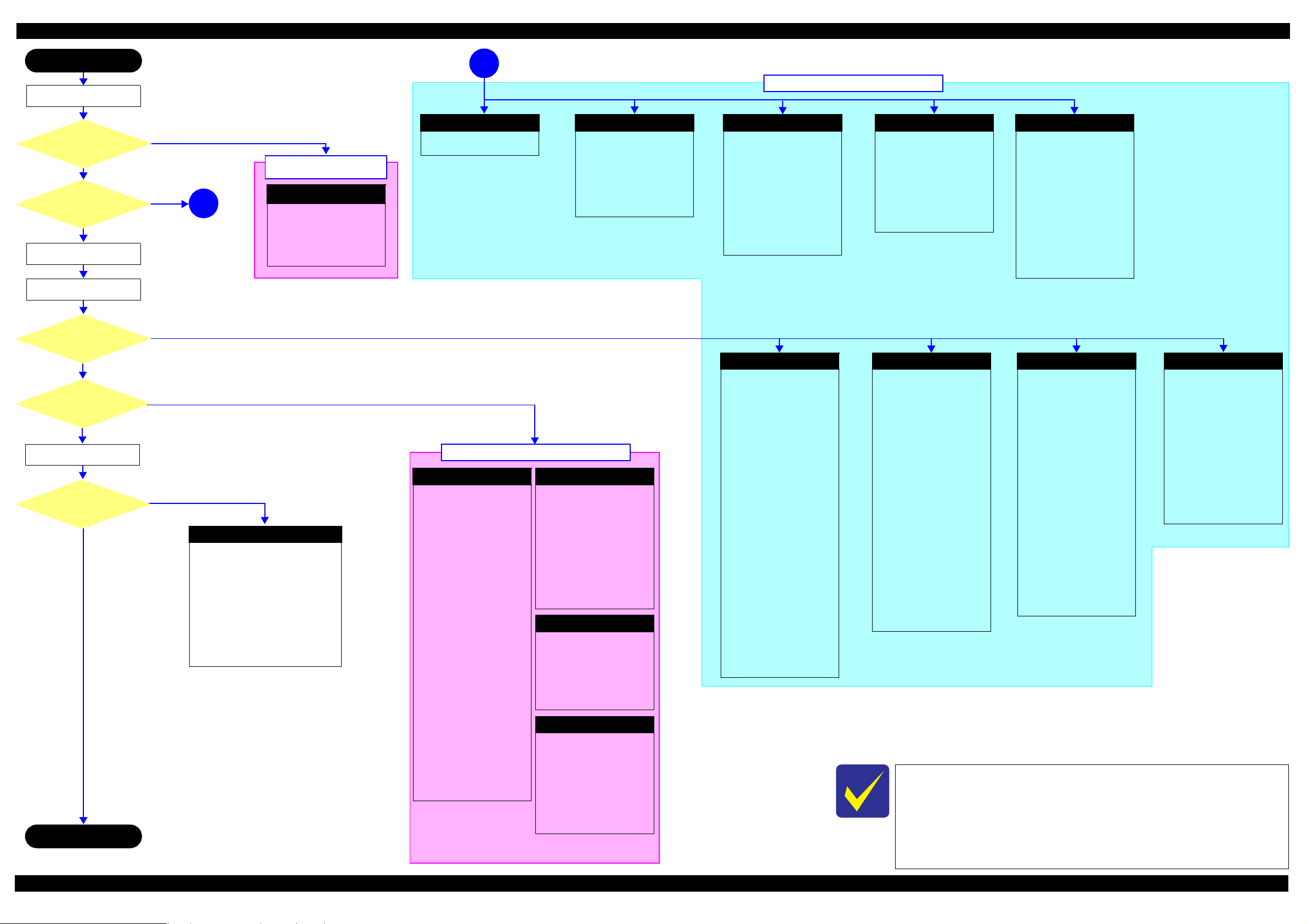
Table 1-1. Condition 1: Normal Power-on Sequence
Operation
1. Printhead initialization and fuse inspection
1-1.Initializes the Printhead, and checks for the fuse on the circuit boards in th e printer.
2. Checking for waste ink overflow
2-1.Checks the waste ink counter if the waste ink overflow i s occurring.
3. Seeking the home position
3-1.The CR Unit move s to the 80-digit side slowly and confirm s it touc hes the Change Lever (CR lock).
*1
*3
Revision A
CR Unit/PF Roller
movement and
position
*2
3-2.The CR Unit move s to the 0-digit side slowly.
3-3.After the PE Sensor checks if paper exists, the PF Motor rotates clockwise for one second and releases the CR lock.
3-4.While c h e ck ing if the CR Unit does not touch the Change Lever (CR lock) or the fo reign materia l, th e CR Unit
moves to the 80-digit sid e s lowly until it touches the Left Frame.
3-5.The distance from the position where the CR Unit touched to the Left Frame is regarded as the standard distance
from the origin position, and the ho m e posi tion is fixed.
From then on , th e CR Unit position is monitored according to the signa ls f rom the CR Encoder.
3-6.The CR Unit move s to near its home position quickly.
4. PF Motor Measureme nt
4-1.The PF Motor rotates clockwise until the PF Roller turns five times to perform a load measurement.
5. Detecting ink cartridg e and initia liz ing ink system
5-1.The CR Unit return s to its hom e po sit ion .
6. Low temperature operation sequence
6-1.The CR Unit quickly moves back and forth bet w ee n near the Change Lever an d nea r the Left Frame for two times.
*5
*4
Note 1: The rotation directions of the PF Motor are as follows.
Clockwise: Paper is fed normally
Counterclockwise: Paper is fed backward
*2: The conditions of the CR lock are as follows.
Red CR lock is set
White CR lock is released
*3: The fatal error occurs if there is a problem such as the fuse blew.
*4: The empty suction operation may occur depending on the situation.
*5: Executed when t he detected temperature is under 5
o
C (41oF) by the thermistor on the Printhead.
Troubleshooting Power-On Sequence 11
Confidential
Page 12
L365/L366,L360/L362,L310/L312,L220/L222,L130/L132 S eries
Condition 2: Power-on sequence after recovering from a paper jam error (See Table 1-2.)
Turning on the printer after turning it off with a paper jam fatal error.
There still remains paper on the paper path out of the detecting area of the PE Sensor.
Maintenance error recovery has never been performed.
Revision A
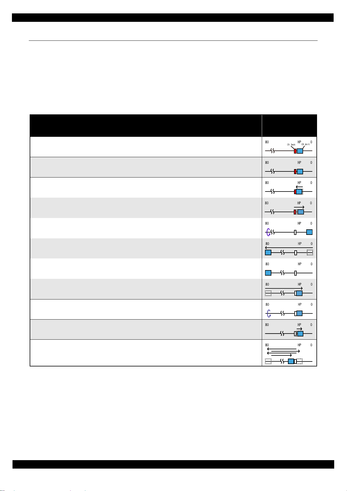
Table 1-2. Condition 2: Power-on Sequence after Recovering from a Paper Jam Error
CR Unit/PF Roller
Operation
Executes No.1 to N o . 3 on the normal power-on se quence (Table 1-1).
4. Detecting rem aining paper
4-1.5.The CR Unit returns to its home position.
4-2.The CR Unit moves to the 80-digit side and confirms there is no paper.
4-3.The CR Unit quickly returns to its home position, and displays on the LCD or with flashing LEDs that the paper jam
error occurs.
When the user remo ves the paper and releases the pap er jam error by panel operation, t h e normal power-on sequence fro m N o.1 (Table 1-1) is executed
*2
again.
Note *1: “Paper exists” is detected when the CR Unit touches the paper. Wh en “pape r does not ex ist” is detect ed, the po wer-on sequence
of condition 1 (
*2: If the paper jam error cannot be solved after repeating the power-on sequence on condition 2 (
into the paper jam fatal error for the third time.
Table 1-1
To recover from the maintenance error, the dedicated software that can be downloaded
) is executed from No.4.
*1
Table 1-2
movement and
position
) twice, the printer turns
from the web site which can be accessed from STM3 is required.
The printer operation related to the maintenance error recovery is as follows.
• When the waste ink counter reaches the threshold value (1) for the first time and the
maintenance error occurs, the counter threshold of the maintenance error is changed
to threshold value 2 af ter performing recovery from the maintenance error.
• After the threshold value (2) is enabled, the warning; to notify the possibility of ink
leakage out of the printer, is displayed every time the waste ink counter increases by
1%.
• If the was te ink counter reaches the t hreshold val ue (2), th e maintenan ce error occur s.
Then, the waste ink counter is changed back to the threshold val ue (1) after reco vering
from the maintenance e rr or, and t he warni ng is di spl aye d re peat edl y acc ordi ng t o the
increment of the waste ink counter until the maintenance error occurs when the
threshold value (2) is reached.
(Recovery from the maintenance error can be performed up to the specified number
of times.)
Troubleshooting Power-On Sequence 12
Confidential
Page 13

L365/L366,L360/L362,L310/L312,L220/L222,L130/L132 S eries
1.3 Fatal Error Code List
This section describes how to check the fatal error code, description, and the possible causes.
1.3.1 Printer Fatal Error Code
This secti on describes the fatal error code and the possible cau se for this product.
Revision A
Error type
Scanner
Printer
Error
code
0x10 HP detection fa ilure
0x14 Measure ment error
0x20 LED light failure
0x51 Auto judg e Fa ta l Error 1
0x52 Auto judg e Fa ta l Error 2
0x53 Auto judg e Fa ta l Error 3
0x54 Auto judg e Fa ta l Error 4
0x55 Auto judg e Fa ta l Error 5
0x60 Home posi ti on
0x63
0x64 Paper-Jam canc elation disable error
0x81 PIS environmental error • Diffused light
0x82 PIS continuous reflected light error
0x83 PIS No refl ec ted light error • PIS failure (installation posture, contam in at ion)
0x84 PIS shift length error
0x87 PIS Empt y Jig error • PIS failure (installation posture, contamination)
0x88 Excessive Light error
0x89 Insufficient Light error
0x8F EEPROM verify error (by command)
Ink cartridge replacement timing contact
detection error (Power off)
Error name Possible cause
• CIS Unit failure
• Scanner Housing failure
• Main Board failure
• Ins u ff icient grease
• Foreign object
• FFC for CIS failure / FFC for CIS connection failure
• Scanner drive mechanism w as overloaded.
• Ins u ff icient grease
• Foreign object
• Lack of gears
• Deformation of the shaft
• CIS Unit failure
• Main Board failure
---*
• Carriage overload error (paper jam/forei gn object)
• Deformation of the Main Frame
• Ink system failure
• CR Motor failure
• Deformation of the Front Frame
• CR Encoder failure (contaminated/detached scale, Encoder Board
failure)
• Cable disconnection
• Paper jam
• Foreign object
• Deformation of the Main Frame
• Paper jam
• Foreign object
• PIS failure
• Main Board failure
• Di ffused light
• Home position gap
• Di ffused light
• PIS failure
• Main Board failure
• Di ffused light
• PIS failure (installation posture, conta m ination)
• Main Board failure
• Ink cartridge failure
---*
Troubleshooting Fatal Error Code List 13
Confidential
Page 14

L365/L366,L360/L362,L310/L312,L220/L222,L130/L132 S eries
Revision A
Error type
Printer
Error
code
0x9A Circuit error (include blowout of a fuse)
0x9B Transistor temperature error
0x9C X-Hot detect error (pre printing)
0x9D X-Hot detect error (after flushi ng)
0x9E Head temperature error
0xB9 Othe r Ink device error
0xBA Other Ink device error
0xC0 CRCM access error
0xC1 CRCM access error
0xC3 Othe r Ink device error
0xE1 CR PID excess load error
0xE2 CR PID excess speed error
0xE3 CR PID reverse error
0xE4 CR PID lock error
0xE8 CR load position reverse error
0xE9 CR load position excess sp eed error
0xEA CR load position ex ce s s lo a d error
0xEE CR PID driving time error
0xEF
0xF1 PF PID excess load error
CR load posi tion excess driving ti m e
error
Error name Possible cause
• Main Board failure
• Printhead failure
• Main Board failure
• Ink cartridge failure
• CSIC Terminal failure
• CR Contact Module failure
• Main Board failure
• Cable disconnection
• CR Encoder failure (contaminated/detached scale, Encoder Board
failure)
• CR Motor failure
• Carriage overload error (paper jam/forei gn object)
• Cable disconnection
• CR Encoder failure (contaminated/detached scale, Encoder Board
failure)
• Motor driver failure (Main Board fai lur e)
• Slipping teeth of the CR Timing Belt
• Imp roper tension of the CR Timin g Belt
• CR Encoder failure (contaminated/detached scale, Encoder Board
failure)
• Slipping teeth of the CR Timing Belt
• Imp roper tension of the CR Timin g Belt
• Carriage overload error (paper jam/forei gn object)
• CR Encoder failure (contaminated/detached scale, Encoder Board
failure)
• CR Motor failure
• Carriage overload error (paper jam/forei gn object)
• Cable disconnection
• CR Encoder failure (contaminated/detached scale, Encoder Board
failure)
• Slipping teeth of the CR Timing Belt
• Imp roper tension of the CR Timin g Belt
• Carriage overload error (paper jam/forei gn object)
• CR Encoder failure (contaminated/detached scale, Encoder Board
failure)
• Motor driver failure (Main Board fai lur e)
• Slipping teeth of the CR Timing Belt
• Imp roper tension of the CR Timin g Belt
• CR Encoder failure (contaminated/detached scale, Encoder Board
failure)
• CR Motor failure
• Carriage overload error (paper jam/forei gn object)
• Cable disconnection
• Main Board failure
• PF Encoder failure (contaminated/detached scale, Encoder Board
failure)
• PF Motor failure
• PF drive mechanism overload (paper jam/foreign object)
• Cable disconnection
Troubleshooting Fatal Error Code List 14
Confidential
Page 15

L365/L366,L360/L362,L310/L312,L220/L222,L130/L132 S eries
Revision A
Error type
Printer
Error
code
0xF2 PF PID excess speed error
0xF3 PF PID reverse error
0xF4 PF PID lock error
0xF8 PF load position reverse error
0xF9 PF load position reverse error
0xFA PF load position excess load error
0xFE PF PID driving time erro r
0xFF PF load position excess driving time error
Error name Possible cause
• PF Encoder failure (contaminated/detached scale, Encoder Board
failure)
• Motor driver failure (Main Board fai lur e)
• Slipping gears have occurred around the PF Motor gears.
• PF Encoder failure (contaminated/detached scale, Encoder Board
failure)
• Slipping gears have occurred around the PF Motor gears.
• Paper jam
• PF Encoder failure (contaminated/detached scale, Encoder Board
failure)
• PF Motor failure
• PF drive mechanism overload (paper jam/foreign object)
• Cable disconnection
• PF Encoder failure (contaminated/detached scale, Encoder Board
failure)
• Slipping gears have occurred around the PF Motor gears.
• PF Encoder failure (contaminated/detached scale, Encoder Board
failure)
• Motor driver failure (Main Board fai lur e)
• Slipping gears have occurred around the PF Motor gears.
• PF Encoder failure (contaminated/detached scale, Encoder Board
failure)
• PF Motor failure
• PF drive mechanism overload (paper jam/foreign object)
• Cable disconnection
• Main Board failure
Note "*": Not occurs except in manufacturing process.
Troubleshooting Fatal Error Code List 15
Confidential
Page 16

CHAPTER 2
DISASSEMBLY/REASSEMBLY
Confidential
Page 17
L365/L366,L360/L362,L310/L312,L220/L222,L130/L132 S eries
2.1 Overview
In this chapter, the product names are called as follows:
L360/L362 Series:L365/L366
L360/L362 Series:L360,L363/L362
L310/L312 Series:L310,L313/L312
L220/L222 Series:L220/L222
L130/L132 Series:L130/L132
This chapter describes procedures for disassembling the main parts/units of this product. Unless otherwise
specified, disassembled parts/units can be re ass embl ed by rev er sing the disassembly proce dur e. See the cautions
or tips for disassembly/reassembly described in "2.3 Detailed Disassembly/Reassembly Procedure for each Part/
Unit (p41)".
Read the "Safety Precautions(p3)" before disassembling and reassembling.
When you have to remove units or parts that are not described in this chapter, see the exploded diagrams of SPI
(Service Parts Information).
2.1.1 Tools
Use only specified tools to avoid damaging the printer.
Name Availability EPSON Part Code
(+) Phillips screwdriver #1 O 1080530
(+) Phillips screwdriver #2 O --Flathead screwdriver O --Flathead Precision screwdriver #1 O --Tweezers O --Longnose pliers O --Acetate ta pe --- 1003963
Note 1: Some of the tools listed above are commercially available.
2: EPSON prov ide s the tools lis te d with EPSON part code.
Revision A
2.1.2 Jigs
Name Quantity EPSON Part Code
Spring hook jig* 1 Can be made with a commerci al item See " Making the Spring Hook Jig (p17)".
Thickness gauge (1.5 mm) 2 Commercially available
Thickness gauge (2.0 mm) 2 Commercially available
Sonic tension meter 1 1294120
Note *: If performing the disassembling/reassembling procedure is difficult using tweezers such as whe n reassembling " Cap Lever/Cap
Assy (p44)", the spring hook jig helps you to remove/attach the spring easier.
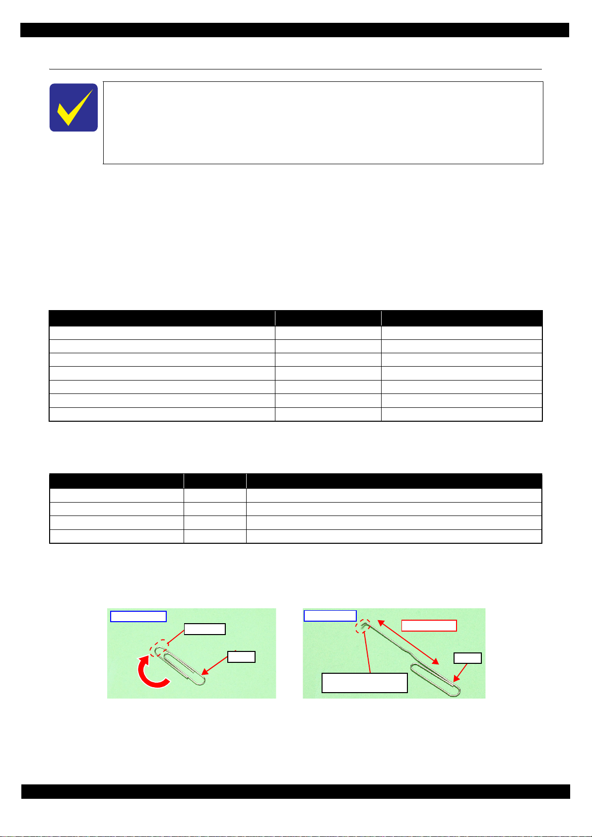
2.1.2.1 Making the Spring Hook Jig
Fold a clip (commercial item) as shown in Fig. 2-1.
Before folding
Fold here
Clip
Figure 2-1. Making the Spring Hook Jig
After folding
40 mm or more
Clip
Fold appropriate length
to hitch a spring.
Disassembly/Reassembly Overview 17
Confidential
Page 18
L365/L366,L360/L362,L310/L312,L220/L222,L130/L132 S eries
2.1.3 Locations of the Parts/Units
This section shows the locations of the main parts/units of this product.
The parts/units which can not be seen in the following pictures are indicated in dotted lines
().
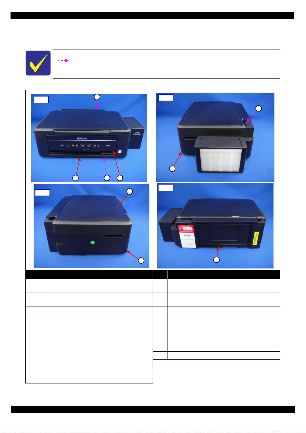
Exterior parts
Revision A
Front
Left
1
2 3 4
Right
5
6
8
Rear
7
No. Name No. Name
Housing Rear (p33) (L365/L366,L360/L362,L220/L222
1
Series only)
2 Tray Front Assy (p33) 6
Frame Base Assy (p35)
3
Panel Unit
• L365/L366 Series (p 35)
Panel Board Assy (p38) / Panel Butto ns (p38) /
Panel Housing Upper Assy (p38) / Panel Housing
4
Lower Assy (p38)
• L36 0/L362,L220/L 2 22 Series (p 35)
Panel Board Assy (p38) / Panel Butto ns (p38) /
Panel Housing Upper Assy (p38) / Panel Housing
Lower Assy (p38)
Hinge (p37) (L365/ L366,L360/L362 ,L220/L222 Series
5
only)
Housing Righ t (p37) (L365/L366,L360/L362,L220/L222
Series only)
Housing Left (p33) (L365/L366,L360/L362,L220/L222
7
Series only)
Scanner Unit (p33) (L365/L366,L360/L362,L220/L222
Series only)
8
9 Paper Support Assy (p33)
Scanner Housing Upper (p37) / Scanner Carriage Unit
(p37) / Scanner Housing Lower (p37) / CIS Module
Unit (p37) / Scanner Motor (p37)
9
Figure 2-2. Exterior Parts
Disassembly/Reassembly Overview 18
Confidential
Page 19
L365/L366,L360/L362,L310/L312,L220/L222,L130/L132 S eries
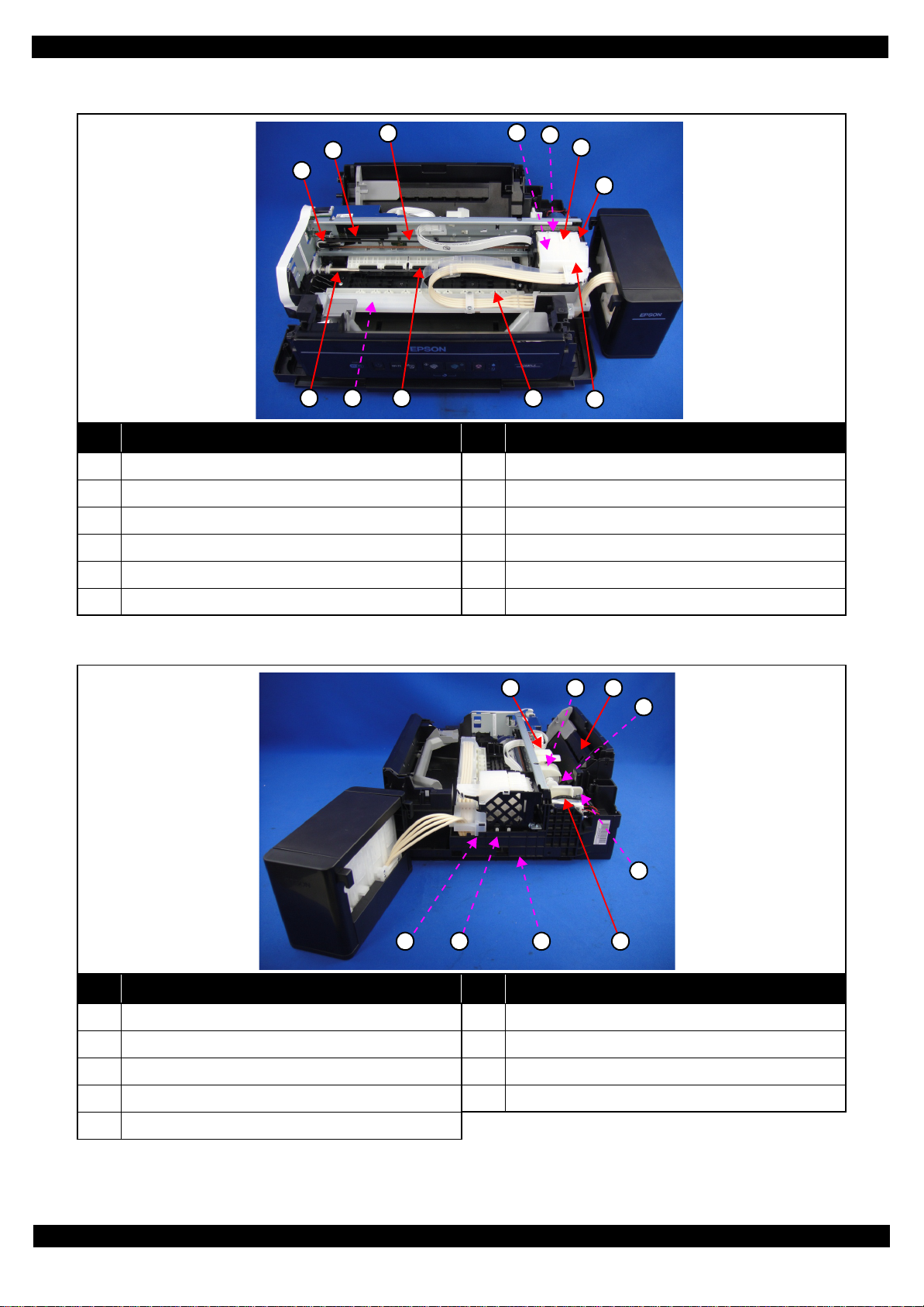
Printer mec hanism
Revision A
3
2
1
8 11
10
9
4
5
6
7
12
No. Name No. Name
1 CR Driven Pulley Assy (p35) 7 CR Unit (p39)
2 CR Scale (p35) 8 PF Roller Unit (p39)
3 CR Timing Belt (p39) 9 Star Wheel Holder Assy (p37)
4 Printhead (p33) 10 Paper Guide Upper Assy (p39)
5 CR Encoder Sensor (p39) 11 Paper Guide Front Unit (p33)
6 Adapter (p37) 12 Adapter Cover (p37)
Figure 2-3. Printer Mechanism: Front
31 2
4
5
6 7 8 9
No. Name No. Name
1 LD Roller Cover (p35) 6 Cap Lever (p37)
2 LD Roller Assy (p35) 7 Cap Assy (p37)
3 Hopper (p35) 8 Porous Pad for Cap Assy (p37)
4 Retard Roller Assy (p33) 9 Pump Unit (p39)
5 Paper Back Lever (p33)
Figure 2-4. Printer Mechanism: Right
Disassembly/Reassembly Overview 19
Confidential
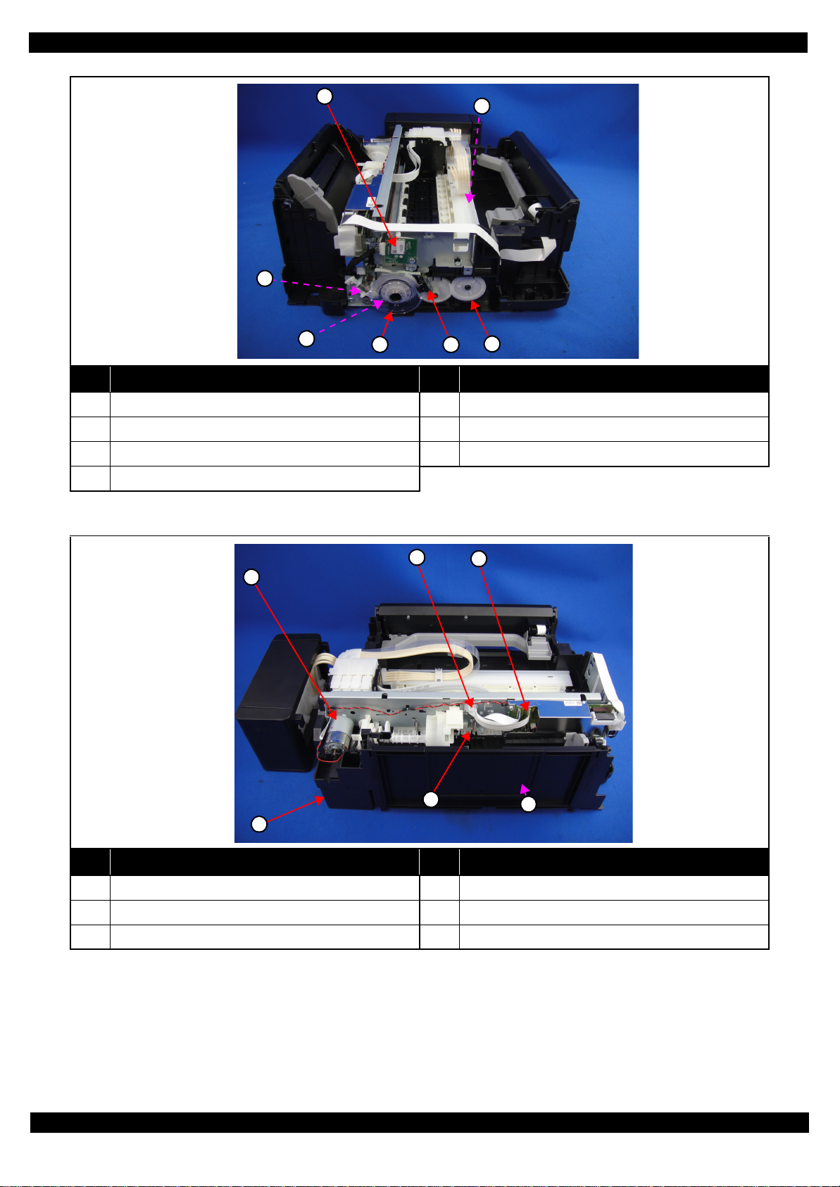
Page 20
L365/L366,L360/L362,L310/L312,L220/L222,L130/L132 S eries
Revision A
1
3
4
5 6
2
7
No. Name No. Name
1 Wireless LAN Module (p33) (L365/L366 Series only) 5 PF Scale (p36)
2 EJ Roller (p37) 6 PF Encoder S ens or (p36)
3 PF Motor Assy (p39) 7 EJ Roller Gear (p33)
4 PF Timing Belt (p36)
Figure 2-5. Printer Mechanism: Left
2
1
5
4
3
6
No. Name No. Name
1 CR Motor (p35) 4 Waste Ink Pad Assy (p33)
2 Head FFC (p39) 5 PE Sensor Lever (p35)
3 Main Board (p35) 6 PS Unit (p33)
Figure 2-6. Printer Mechanism: Rear
Disassembly/Reassembly Overview 20
Confidential
Page 21
L365/L366,L360/L362,L310/L312,L220/L222,L130/L132 S eries
Ink Supply Tank Assy
Revision A
2
1
10
No. Name No. Name
1 Cover Joint (p36) 7 Guide Tube Tank (p36)
2 Top Cover (p36)
3 Right Cover (p36)
4 Ink Supply Tank Tube Assy (p36)
5 Ink Supply Tube Assy (p37) 9 Bottom Cover (p36)
3
4
9
5
6
7
8
Ink Supply Tank
8
Ink Supply Tank (Cy an) (p36 ) /In k Sup ply Tank
(Magenta) (p36)/Ink Supply Tank (Yellow) (p36)/Ink
Supply Tank (Black) (p36)
6 Cover Tube Tank (p36) 10 Left Cover (p36)
Figure 2-7. Ink Supply Tank Assy
Disassembly/Reassembly Overview 21
Confidential
Page 22

L365/L366,L360/L362,L310/L312,L220/L222,L130/L132 S eries
2.1.4 Standard Operation Time for Servicing the Product
The following are the standard operation time for servicing the product. This standard operation time was
determined with the MTTR result measured using the prototype of L360/L362 Series which have the most
functions. For othe r models descr ibed i n this manua l, perf orm the re pair work r eferr in g to th is st andard operat ion
time though the time varies due to the structural difference between models.
The underlined parts/units are supplied as After Service Parts.
Table 2-1. Standard Operation Time
Time (mm:ss)
Parts/Unit
Replacement
Housing Rear 0:49 --- 0:49
Paper Support Assy
Tray Front Assy
Document Cover
Star Wheel Holder Assy
Paper Guide Front Unit
Holder Board 3:16 --- 3:16
FFC Cover Outer 2:05 --- 2:05
Print Head
Waste Ink Pad Assy
Paper Back Lever
Retard Roller Assy
Scanner Unit
Scanner Housing Upper 3:17 --- 3:17
Scanner Housing Lower 3:17 --- 3:17
CIS Module Unit 3:26 --- 3:26
Spacer 3:54 --- 3:54
CIS Module 3:54 --- 3:54
Scanner Carriage Unit 3:37 --- 3:37
Scanner Carriage 4:15 --- 4:15
CIS Holder Unit 7:05 --- 7:05
Scanner Mot o r 7:05 2:52 9:57
Housing Left
PS Unit
PF Encoder Sensor
PF Scale
PF Driven Pully Assy 4:10 1:10 5:20
PF Timing Belt 4:57 1:10 6:07
Wireless LAN Module
EJ Roller Gear
EJ Roller
Hinge 2:02 --- 2:02
Housing Right
Cap Assy
Porous Pad for Cap Assy 3:23 --- 3:23
0:12 --- 0:12
0:13 1:31 1:44
0:10 --- 0:10
3:47 3:18 7:05
0:37 7:44 8:21
4:54 17:39 22:33
0:31 0:45 1:16
1:41 --- 1:41
1:49 0:47 2:36
1:46 2:52 4:36
2:44 --- 2:44
3:13 1:28 4:41
3:20 --- 3:20
3:35 --- 3:35
3:18 --- 3:18
2:58 --- 2:58
5:08 3:18 8:26
2:16 --- 2:16
3:16 --- 3:16
Adjustment/
inspection
Revision A
Total
Disassembly/Reassembly Overview 22
Confidential
Page 23

L365/L366,L360/L362,L310/L312,L220/L222,L130/L132 S eries
Table 2-1. Standard Operation Time
Parts/Unit
Cap Lever 3:32 --- 3:32
Panel Unit
Panel Housing Lower Assy 5:02 --- 5: 02
Panel Board Assy 5:21 --- 5: 21
Panel Bottons 5:37 --- 5: 37
Panel Housing Upper Assy
CR Scale
LD Roller Cover 4:03 --- 4:03
LD Roller Assy
Hopper
FFC Holder MB 4:45 --- 4:45
Shield Plate 7:56 --- 7:56
PE Sensor Lever
Main Board
CR Motor
CR Driven Pulley Assy 3:49 3:07 6:56
Main Frame Assy 7:15 11:16 18:31
Paper GuideUpper Assy
CR Unit
CR Timing Belt
CR Encoder Sensor 13:13 --- 13:13
Head FFC
FFC Holder 13:51 --- 13:51
Frame Base Ass y 8:07 8:51 16:58
Pump Unit
PF Grounding Spring 10:12 --- 10:12
Spur Gear 16.5 10:21 --- 10:21
PF Roller Unit
PF Motor Assy
Frame Base 11:43 6:53 18:36
Tube Cover 0:2 2 --- 0:22
Ink Supply Tank Assy 4:57 --- 4:57
Top Cover
Cap Tank
Bottom Cover
Cover Tube Tank
Guide Tube Tank
Left Cover
Right Cover
Cover Joint
Ink Supply Tank (Magenta)
Ink Supply Tank (Yellow)
EEPROM Data Copy OK 8:37 1:10 9:47
EEPROM Data Copy NG 8:37 27:58 36:35
Time (mm:ss)
Replacement
4:21 --- 4:21
5:37 --- 5:37
4:06 --- 4:06
5:29 0:47 6:16
4:06 6:03 10:09
9:26 0:47 10:13
8:44 1:00 9:44
9:20 7:21 16:41
12:52 9:52 22:44
12:31 0:40 13:11
14:19 --- 14:19
9:53 --- 9:53
13:11 5:51 19:02
11:43 1:08 12:51
0:10 --- 0:10
0:22 --- 0:22
1:44 --- 1:44
0:55 --- 0:55
1:06 --- 1:06
2:34 --- 2:34
2:07 --- 2:07
2:39 --- 2:39
4:11 --- 4:11
4:11 --- 4:11
Adjustment/
inspection
Revision A
Total
Disassembly/Reassembly Overview 23
Confidential
Page 24

L365/L366,L360/L362,L310/L312,L220/L222,L130/L132 S eries
Table 2-1. Standard Operation Time
Parts/Unit
Ink Supply Tank (Cyan) 4:11 --- 4:11
Ink Supply Tank (Black )
Ink Supply Tank Tube Assy
Tube Guide Sheet Sub
Tube Pressing Plate
Ink Supply Tube Guide 1st
Ink Supply Tube Guide 2nd
Joint
Adapter Cover
Ink Supply Tube Assy
Tube Guide Sheet
Adapter
Time (mm:ss)
Replacement
4:11 --- 4:11
3:30 --- 3:30
0:30 --- 0:30
0:52 --- 0:52
0:06 --- 0:06
3:25 --- 3:25
2:20 --- 2:20
0:37 --- 0:37
2:11 --- 2:11
1:39 --- 1:39
1:49 --- 1:49
Adjustment/
inspection
Revision A
Total
Disassembly/Reassembly Overview 24
Confidential
Page 25

L365/L366,L360/L362,L310/L312,L220/L222,L130/L132 S eries
2.1.5 Checks and Precautions before Disassembling
2.1.5.1 Factors which Affect the Print Quality
HOW TO PLACE THE INK TANK ASSY WHEN DISASSEMBLING/REASSEMBLING
Do not place the Ink Supply Tank Assy with Ventilati on Hole si de down. Oth erwi se , ink in the Ink Supply Tank
Assy may reach and cover the ventilation Hole, and the ink in the Ink Supply Tank Assy may leak.
In order to prevent this from occurring, make sure to place the Ink Supply Tank Assy as shown below after
removing it.
Revision A
OK
NG
Ink Supply Tank Assy
Ventilation Hole
Ink Supply Tank Assy
Figure 2-8. How to Place the Ink Tank Assy
Disassembly/Reassembly Overview 25
Confidential
Page 26

L365/L366,L360/L362,L310/L312,L220/L222,L130/L132 S eries
2.1.5.2 Factors which Affect the Safety of Service Personnel such as Ink Leakage during Operation
Ink may spill when removing the following parts from L365/L366,L360/L362,L310/L312,L220/L222,L130/
L132 Series.
This section describes the parts that may cause ink spill and the means to minimize the ink spill when removing
the parts.
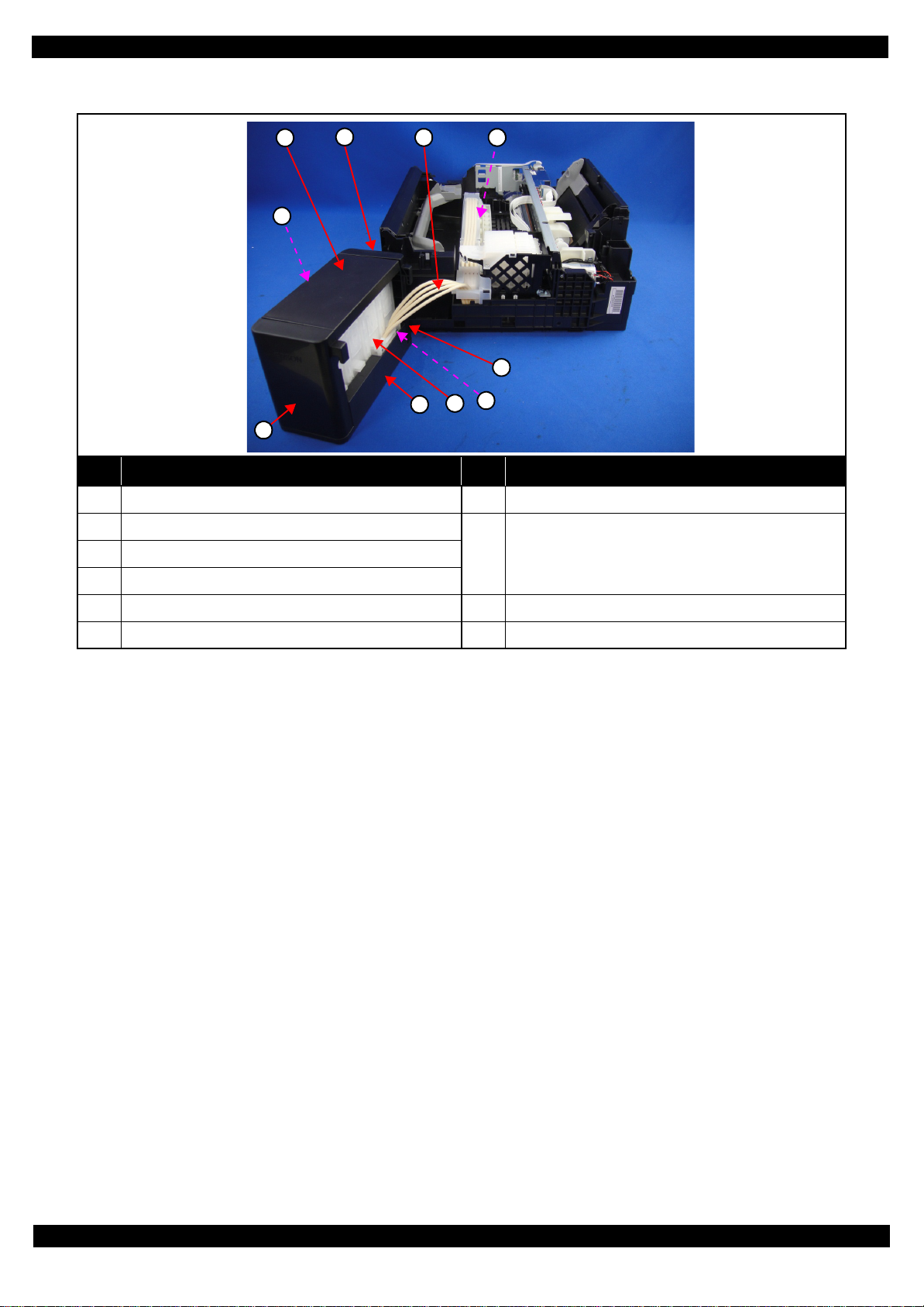
THE PARTS THAT MAY CAUSE INK SPILL WHEN REMOVING
Parts When ink may spill Location
Joint Removing the Ink Supply Tank Tube Assy / Ink Supply Tube Assy from the Joi nt A
Revision A
Ink Supply
Tank
Ink Supply
Tank Tube Assy
Adapter Removing the Ink Supply Tube Assy from the Adapter C
Ink Supply
Tube Assy
Note : These parts are indicated with the icon in disassembly/reassembly flowchart. (See "2.2 Disassembly/Reassembly Procedures
(p31)".)
• Removing the tubes of the Ink Supply Tank Tube Assy from the Joint
• Removing the tubes of the Ink Supply Tank Tube Assy from the Ink Supply Tank
• Removing the Ink Supply Tank Tube Assy / Ink Supply Tube Assy from the Joint
• Removing the Ink Supply Tube Assy from the Adapter
Joint Ink Supply Tank Assy
Adapter
C
A, B
A, C
A
B
Ink Supply Tank Tube Assy Ink Supply Tube Assy
Figure 2-9. Location
Disassembly/Reassembly Overview 26
Confidential
Page 27

L365/L366,L360/L362,L310/L312,L220/L222,L130/L132 S eries
MEANS DO TO MINIMIZE THE INK SPILL
Even observing the points described in t his section, in k may spill in the following situations.
Therefore, be careful not to contaminate the inside of the printer or its surroundings by
preparing the container to receive the leaked ink, or the like.
When removing the Ink Supply Tank Tube Ass y, some ink wi ll spil l from both ends of the
tube .
When removing the Ink Supply Tube Assy, all the ink in the tube will spill.
Before disassembling, confirm that the printer is in the foll owing condi tion.
Adapter is re moved
Before disconnecting the joint parts of the ink path, make sure that the Adapter is removed from the Carriage.
Revision A
Carriage
Adapter
Ink path
Figure 2-10. Adapter
Disassembly/Reassembly Overview 27
Confidential
Page 28

L365/L366,L360/L362,L310/L312,L220/L222,L130/L132 S eries
DISCHRGING INK FROM THE INK SUPPLY TANK
Discharging ink is recommended only when disconnecting the Ink Supply Tank Tube Assy from the Ink Supply
Tank. Before performing the above disconnection, discharge ink from the Ink Supply Tank as follows.
Necessary tools
•
Containers (x 4) for each discharged ink
•
Injector (w ith a tip of φ3.2 mm)
•
Clips (x 2)
•
Cotton swab (x 4)
When disconnecting t he Ink Sup ply Tube/ Ink Suppl y TankTube f rom the Joint, ink may
leak from the ink tube. Preparea container to receive the leaking ink to prevent the
productfrom getting contaminated by the leaked ink .
Prior to the following steps, connect the injector with the tube, and then discharge ink
according to the procedure.
Discharging preparation
1. Remove the screw (x 3) of the Guide Tube 1st and the Tube Pressing Plate .
2. Release the hook of the Guide Tube Sub , Release the Guide Tube from Dowel .
3. Release the Ink Supply Tube from rib, and release the Guide Tube 1st from the Frame Base Assy.
Revision A
Ink Supply Tube
Tube Pressing Plate
Guide Tube & Sub
Figure 2-11. Discharging preparation (1)
4. Move the Carriage to right side .
5. Release the Joint from the rib of Guide Tube 1st .
Guide Tube 1st
Guide Tube 1st
Rib
C.B.P. 3x10 (6.1±1 Kgfcm)
C.B.P. 3x10 (6.1±1 Kgfcm)
Ink SupplyTank
Joint
Carriage
Frame Base Assy
Guife Tube 1st
Figure 2-12. Discharging preparation (2)
Disassembly/Reassembly Overview 28
Confidential
Page 29

L365/L366,L360/L362,L310/L312,L220/L222,L130/L132 S eries
Discharging procedure
1. Release the Ink Supply Tank Assy.(
Refer to
2. Place the Ink Supply Tank Assy on a place where its bottom is higher than the top of the Printhead.
3. To minimize the ink leakage fr om the Ink Supply Tube / Ink Supply Tank Tube , pinch the Ink Supply
Tube / Ink Supply Tank Tube with clips (x 2) .
Joint
Ink Supply Tube
Revision A
Cotton swab (x 4) (p.28))
Container
Clip (x 2)
Figure 2-13. Discharging Ink (1)
4. Prepare a container for ink to discharge, then disconnect the Ink Supply Tube from the joint and put its
tip into the container for the ink.
5. To discharge the ink in the Ink Supply Tank Assy to the container.
Ink Supply Tube
Joint
Container for discharged ink
Ink Supply Tank Assy
Figure 2-14. Discharging Ink (2)
6. Move the clips (x2) so that only the ink to discharge can flow in the Ink Supply Tank Tube .
7. The ink in the Ink Supply Tank is discharged into the container through the Ink Supply Tank Tube.
8. Repeat step 4 to Step 7 for all ink tanks to discharge all ink in the Ink Supply Tank .
Ink Supply Tank Tube
Joint
Clip
Tube
Injector
φ
3.2 mm)
(tip of
Figure 2-15. Discharging Ink (3)
Disassembly/Reassembly Overview 29
Confidential
Page 30

L365/L366,L360/L362,L310/L312,L220/L222,L130/L132 S eries
It is recommended that the ink in the Ink Supply Tank should be discharged completely before
proceeding to disassembling/reassembling.
After all the reassembling work is complete, the discharged ink of each color should be refilled
back to the Ink Supply Tank before performing the adjustment. Confirm the colors indicated on
the film of the Ink Supply Tank so as not to mistake them, and make sure to refill each ink back to
the correct tank from the corresponding ink supply hole.
Ink supply hole
Revision A
Ink Supply Tank Assy
Disassembly/Reassembly Overview 30
Confidential
Page 31

L365/L366,L360/L362,L310/L312,L220/L222,L130/L132 S eries
2.2 Disassembly/Reassembly Procedures
This section describes procedures for disassembling the parts/units in a flowchart format. For some parts/units,
detailed procedures or precautions are provided (accordingly indicated by icons and cell's color). Refer to the
explanations in the example chart below and perform an appropriate disassembling and assembling procedure.
(See "2.3 Detailed Disassembly/Reassembly Procedure for each Part/Unit (p41)".)
For routing cables, see "2.4 Routing FFCs/cables (p50)".
The example below shows how to see the charts on the following pages.
The name enclosed in gra y
indicate a part/unit that
must be removed on the
way to the target parts.
Shows necessary
procedures before removing
the following parts.*
Paper Guide
Upper Assy (p29)
CR Timing Belt
FFC/ Cable *5
Shows the procedure
number on the “FFC/
cable list”.
Revision A
Black letters indicate a part/
unit not supplied as an ASP.
Item Description Reference
Parts/unit name
White-letter
Black-letter
Icon
Frame Base Assy
---
---
(p21) (p27)
as a unit/assy. is available.
Note "*": The box with only part nam es mea ns th e removal of the parts. If the name of
FFC or a cable is shown, disconnect the FFC or cable from the connector.
Part/unit supplied as an ASP --Part/unit not supplied as an ASP --Indicates a practice or conditio n that could result in
injury or loss of life if not strictly observed.
Indicates a practice or conditio n that could result in
damage to, or destruction of equipm e nt if not strictly
observed.
Indicates the parts that are inevitably broken in the
disassembling procedure, and should be replaced with
a new one for reassembly.
Indicates the par ts that may cause the ink spill when
they are removed.
Indicates necessary check items in the disassembling/
assembling procedure.
Indicates supp lementary explanation for disassembly
is given.
Indicates particular tasks to keep quality of the units
are required.
Indicates particular routing of cables is required.
Indicates particular adjustment(s) is/are required. Chapter 3 " Adjustment (p53)"
Indicates lubricatio n is re quired.
Indicates the number of screws securing the parts/
units.
Indicates the points secured with other than a screw
such as a hook, rib, dowel or the like .
Housing Rear
S4
(p22) (p43)
Reference pageShows removal/installation
White letters indicate a
part/unit supplied as an
ASP.
1
Shows the screw types and
the specified torque on the
4
“Screw type/torque list”.
Indicates the reference page in
blue-letter
Indicates the reference page in
blue-letter
Indicates the reference page in
blue-letter
"2.1.5 Checks and Precautions
before Disassembling (p25)"
Indicates the reference page in
blue-letter
Indicates the reference page in
blue-letter
Indicates the reference page in
blue-letter
Indicates the reference page in
blue-letter
Chapter 4 " Maintenance
(p65)"
---
---
Disassembly/Reassembly Disassembly/Reassembly Procedures 31
Confidential
Page 32

L365/L366,L360/L362,L310/L312,L220/L222,L130/L132 S eries
2.2.1 Disassembly Flowchart
L365/L366,L360/L362,L310/L312,L220/L222,L130/L132 Series described in this manual have differences in
their structure because the same printer mechanism is used for some of them and the composition of housings or
functions differs.
The functions and differences according to the models are as follows.
Table 2-2. Function List According to Models
Item
Scanner
Movable type O --- --- --- ---
Panel
Wireless LAN O --- --- --- --Low cost parts --- --- O --- O
Disassembly Flowchart Start Position p 33 p 33 p 33 p 34 p 34
Locked type --- O O --- --Button type --- --- --- O O
L365/L366
Series
O O O --- ---
Table 2-3. Components According to Functions
Item Specification
The shape and unit of components below differ due to the difference of specifications of Scanner Unit.
Scanner
Panel
Wireless LAN
Low cost parts
• Scanner Unit
•Hinge
• Housing Rear/Left/Right
The shape and unit of components bel ow differ due to the difference of specification s of Panel Unit.
•Panel Unit
The following part is not mounted on the models without the Wireless LAN.
• Wireless LAN Module
• CR Timing Belt
• CR Motor
•PF Motor
• Housings, others
L360/L362
Series
L220/L222
Series
•Main Board
• Shield Plate
L310/L312
Series
Revision A
L130/L132
Series
Therefore, parts and units are colored and classified into 5 types in the flowchart given in this section.
Common parts/unit: Black
L365/L366,L360/L362,L220/L222 Series: Blue
L365/L366 Series: Red
L310/L312,L130/L132 Series: Green
L220/L222,L130/L132 Series: Orange
Disassembly/Reassembly Disassembly/Reassembly Procedures 32
Confidential
Page 33

L365/L366,L360/L362,L310/ L312,L2 20/ L222,L 130/ L132 Seri es Revision A
START
Housing Rear
S4
(p 41)
Scanner FFC (CN11)
Ferrite core
Scanner Unit
S4
(p 53)
Housing Left
S4
Paper Support
Assy
1
4
---
---
2
Tray Front Assy
(p 53)
---
4
Paper Guide
Front Unit
S4
(p 43)
2
2
(p 53)
Document Cover
---
Document Mat
---
2
(p 41)
---
---
Waste Ink Pad
Assy
S4
(p 41)
Extension Spring (x2)
1
2
(p 53)
Adapter Cover
(p37)
Adapter (p37)
FFC Cover Outer
over
---
1
(p 37)
4
---
---
Ink Supply Tank Tube
1
Paper Back
Lever
---
1
2
(p 37)
2
(p 65)
2
CR Encoder FFC
(p 43)
Holder Board
Ink Supply Tank
Assy
---
---
---
B
(p 36)
Retard Roller
Assy
FFC Holder
1
5
---
1
(p 37)
3
(p 53)
---
---
2
Head FFC
---
2
(p 41)
Hinge (p37)
Housing Right
(p37)
Cable (CN501)
(p 51)
PS Unit
EJ Roller Gear
Wireless LAN
Module
---
---
---
(p 43)
(p 65)
A
(p 35)
(p 41)
(p 53)
2
(p 51)
The following parts can be replaced without removing the Scanner Unit. However, the
working space for replacement is narrow and dark. Therefore, if you find it difficult to
work, remove the Scanner Unit first before replacement.
Printhead/Holder Board
Paper Guide Front Unit
S5
(p 43)
Panel FFC* 1
2
FFC Holder MB
--1
S7
---
2
FFC/cable list
No. FFC/Cable
1 Disconnect th e Panel FFC (CN2), and remove the ferri te core .
Flowchart 2-1. Disassembly Flowchart (1)
C
(p 36)
Common parts/unit
L365/L366 Series specific parts/
unit
L365/L366,L360/L362,L220/
L222 Series specific parts/unit
L310/L312,L130/L132 Series
specific parts/unit
L210/L222,L130/L132 Series
specific parts/unit
Printhead
3
(p 44)
S11
(p 53)
---
Screw type/torque list
Symbol Screw Type Torque
S1
C.B.P-TITE SCREW 2.5x8 F/ZN-3C 3 ± 1 kgf·cm
S2
C.B.P-TITE SCREW 2x8 F/ZN-3C 4 ± 1 kgf·cm
S3
C.B.P-TITE SCREW 3x10 F/ZN-3C 5
S4
C.B.P-TITE SCREW 3x10 F/ZN-3C 6 ± 1 kgf·cm
S5
C.B.S-TITE SCREW 3x6 F/ZN-3C 4
S6
C.B.S-TITE SCREW 3x6 F/ZN-3C 6 ± 1 kgf·cm
S7
C.B.S-TITE SCREW 3x8 F/ZN-3C 6
S8
C.P SCREW 3x4 F/ZN-3C 4 ± 1 kgf·cm
S9
C.P.F.B-TITE SCREW 2x 8 F/ZN-3C 4
S10
C.P.S-TITE (P2) SCREW 3x6 F/ZN-3C 7 ± 1 kgf·cm
S11
C.B.P-TITE SCREW 2.5x8 F/ZN-3C 5
S12
C.P SCREW 2.6x3 F/ZN-3C 4 ± 0.5 kgf·cm
S13
C.B.S-TITE SCREW 3x4 F/ZN-3C 2
S14
C.B.P-TITE SCREW 2x8 F/ZN 2 ± 0.5 kgf·cm
S15
C.B.P-TITE SCREW 2x8 F/ZN 25
S16
C.B.P-TITE SCREW 3x6 F/ZN 4 ± 1 kgf·cm
S17
C.B.P-TITE SCREW 2.5x8 F/ZN 6
S18
C.B.P-TITE SCREW 2.6x5 F/ZN 3 ± 0.5 kgf·cm
S19
C.B.P-TITE SCREW 3x6 F/ZN 3
±
1 kgf·cm
±
0.5 kgf·cm
±
1 kgf·cm
±
1 kgf·cm
±
0.5 kgf·cm
±
0.5 kgf·cm
±
±
1 kgf·cm
±
0.5 kgf·cm
0.5 kgf·cm
Disassembly/Reassembly 33
Confidential
Page 34

L365/L366,L360/L362,L310/ L312,L2 20/ L222,L 130/ L132 Seri es Revision A
START
Housing Upper
Assy
S5
(p 49)
Paper Support
Assy
4
3
---
2
Printer Cover
---
2
Waste Ink Pad
Assy
S5
1
2
Printer Cover
(p34)
---
---
(p 41)
Extension Spring (x2)
(p 53)
Housing Upper
---
---
---
Buttons
Paper Back
Lever
(p 65)
---
2
1
S5
3
Retard Roller
Assy
---
---
2
(p 53)
Ink Supply Tank Tube
C
4
Housing Front
(p34)
PF Motor Cover
(p34)
(p 35)
A
Housing Front
S6
---
Tray Front Assy
Tray Front Rail
Left/Right
S5
(p 49)
(p 53)
FFC Cover Outer
Cable (CN501)
EJ Roller Gear
FFC Holder
Extension Spring (×2)
Pump Tube
Ink Supply Tank
Assy
(p 36)
(p 38)
---
3
2
(p 43)
2
4
---
1
PF Motor Cover
---
PS Unit
(p 41)
---
2
(p 53)
---
2
(p 51)
Paper Guide
Front Unit
S5
(p 43)
(p 43)
2
2
(p 53)
Flowchart 2-2. Disassembly Flowchart (2)
(p 65)
---
---
(p 51)
Porous Pad for
Cap Assy
---
---
1
Cap Assy
---
(p 44)
3
Screw type/torque list
Cap Lever
---
---
(p 44)
---
---
Common parts/unit
L365/L366 Series specific parts/
unit
L365/L366,L360/L362,L220/
L222 Series specific parts/unit
L310/L312,L130/L132 Series
specific parts/unit
L210/L222,L130/L132 Series
specific parts/unit
---
Symbol Screw Type Torque
S1
C.B.P-TITE SCREW 2.5x8 F/ZN-3C 3 ± 1 kgf·cm
S2
C.B.P-TITE SCREW 2x8 F/ZN-3C 4 ± 1 kgf·cm
S3
C.B.P-TITE SCREW 3x10 F/ZN-3C 5
S4
C.B.P-TITE SCREW 3x10 F/ZN-3C 6 ± 1 kgf·cm
S5
C.B.S-TITE SCREW 3x6 F/ZN-3C 4
S6
C.B.S-TITE SCREW 3x6 F/ZN-3C 6 ± 1 kgf·cm
S7
C.B.S-TITE SCREW 3x8 F/ZN-3C 6
S8
C.P SCREW 3x4 F/ZN-3C 4 ± 1 kgf·cm
S9
C.P.F.B-TITE SCREW 2x 8 F/ZN-3C 4
S10
C.P.S-TITE (P2) SCREW 3x6 F/ZN-3C 7 ± 1 kgf·cm
S11
C.B.P-TITE SCREW 2.5x8 F/ZN-3C 5
S12
C.P SCREW 2.6x3 F/ZN-3C 4 ± 0.5 kgf·cm
S13
C.B.S-TITE SCREW 3x4 F/ZN-3C 2
S14
C.B.P-TITE SCREW 2x8 F/ZN 2 ± 0.5 kgf·cm
S15
C.B.P-TITE SCREW 2x8 F/ZN 25
S16
C.B.P-TITE SCREW 3x6 F/ZN 4 ± 1 kgf·cm
S17
C.B.P-TITE SCREW 2.5x8 F/ZN 6
S18
C.B.P-TITE SCREW 2.6x5 F/ZN 3 ± 0.5 kgf·cm
S19
C.B.P-TITE SCREW 3x6 F/ZN 3
---
B
(p 36)
±
1 kgf·cm
±
0.5 kgf·cm
±
1 kgf·cm
±
1 kgf·cm
±
0.5 kgf·cm
±
0.5 kgf·cm
±
0.5 kgf·cm
±
1 kgf·cm
±
0.5 kgf·cm
Disassembly/Reassembly 34
Confidential
Page 35

L365/L366,L360/L362,L310/ L312,L2 20/ L222,L 130/ L132 Seri es Revision A
L365/L366,L360/L362, L220/L222 Series: (p 33)
A
L310/L312,L130/L132 Series: (p 34)
PF Encoder
Sensor (p36)
FFC /Cable* 2
CR Scale
Paper Support
Assy (p33)
CR Timing Belt
LD Roller Cover
PF Scale (p36)
CR Scale (p35)
CR Driven
Pulley Assy (p35)
LD Roller Cover
(p35)
FFC/Cable* 3
Extension Spring (x3)
Main Frame Assy
S4 S6
(p 44)
(p 65)
Frame Base Assy
(p 53)
(p 53)
---
---
---
Panel Unit
(p 42)
(p 65)
---
(p 50)
---
2
Panel Unit
(p 41)
2
4
(p 42)
S4
4
(p 50)
Hopper
(p 53)
---
2
FFC Holder MB
(p 38)
5
(p 38)
6
(p33)
CR Driven Pulley
Assy
(p 45)
(p 65)
LD Roller Cover
(p35)
---
4
CR Driven Pulley
Assy
S6
(p 45)
1
4
(p 65)
S4
---
FFC/cable list
1
1
No. FFC/Cable No. FFC/Cable
5
7
(p 39)
FFC/Cable* 4
LD Roller Assy
Remove/disconnect the
following.
Panel FFC (CN2)
2
(double-sided tape)
---
Shield Plate
2
3
S6
S13
---
8
(p 39)
FFC/Cable* 5
LD Roller Cover
(p35)
CR Timing Belt
FFC/Cable* 6
---
(p 43)
(p 53)
(p 65)
Remove/disconnect the
following.
Panel FFC (CN2)
(double-sided tape)
3
PF Motor cable (CN13)
PS Unit cable (CN501)
CR Motor cable (CN12)
Remove/disconnect the
following.
Head FFC (CN102)
4
CR Encoder FFC (CN6)
PF Motor cable (CN13)
PS Unit cable (CN501)
Remove/disconnect all FFCs/
cables.
5
Release the CR Motor cable
6
from the hooks of the Main
Frame and Frame Base.
Main Board
Main Board
1
2
Extension Spring
PE Sensor Lever
S7
---
S6 S7
---
---
(p 43)
(p 53)
(p 50)
(p 43)
(p 50)
(p 53)
(p 53)
When the C R Unit or the Head FFC is removed from the Main F rame Assy, re move the
following parts before removing the Main Frame Assy.
FFC Cover Outer
Holder Board
Printhead
CR Motor
2
S8
(p 51)
2
---
(p 53)
Flowchart 2-3. Disassembly Flowchart (3)
CR Motor
S12
(p 51)
(p 53)
2
---
Common parts/unit
L365/L366 Series specific parts/
unit
L365/L366,L360/L362,L220/
L222 Series specific parts/unit
L310/L312,L130/L132 Series
specific parts/unit
L210/L222,L130/L132 Series
specific parts/unit
Screw type/torque list
Symbol Screw Type Torque
S1
C.B.P-TITE SCREW 2.5x8 F/ZN-3C 3 ± 1 kgf·cm
S2
C.B.P-TITE SCREW 2x8 F/ZN-3C 4 ± 1 kgf·cm
S3
C.B.P-TITE SCREW 3x10 F/ZN-3C 5
S4
C.B.P-TITE SCREW 3x10 F/ZN-3C 6 ± 1 kgf·cm
S5
C.B.S-TITE SCREW 3x6 F/ZN-3C 4
S6
C.B.S-TITE SCREW 3x6 F/ZN-3C 6 ± 1 kgf·cm
S7
C.B.S-TITE SCREW 3x8 F/ZN-3C 6
S8
C.P SCREW 3x4 F/ZN-3C 4 ± 1 kgf·cm
S9
C.P.F.B-TITE SCREW 2x 8 F/ZN-3C 4
S10
C.P.S-TITE (P2) SCREW 3x6 F/ZN-3C 7 ± 1 kgf·cm
S11
C.B.P-TITE SCREW 2.5x8 F/ZN-3C 5
S12
C.P SCREW 2.6x3 F/ZN-3C 4 ± 0.5 kgf·cm
S13
C.B.S-TITE SCREW 3x4 F/ZN-3C 2
S14
C.B.P-TITE SCREW 2x8 F/ZN 2 ± 0.5 kgf·cm
S15
C.B.P-TITE SCREW 2x8 F/ZN 25
S16
C.B.P-TITE SCREW 3x6 F/ZN 4 ± 1 kgf·cm
S17
C.B.P-TITE SCREW 2.5x8 F/ZN 6
S18
C.B.P-TITE SCREW 2.6x5 F/ZN 3 ± 0.5 kgf·cm
S19
C.B.P-TITE SCREW 3x6 F/ZN 3
±
1 kgf·cm
±
0.5 kgf·cm
±
1 kgf·cm
±
1 kgf·cm
±
0.5 kgf·cm
±
0.5 kgf·cm
±
±
1 kgf·cm
±
0.5 kgf·cm
0.5 kgf·cm
Disassembly/Reassembly 35
Confidential
Page 36

L365/L366,L360/L362,L310/ L312,L2 20/ L222,L 130/ L132 Seri es Revision A
L365/L366,L360/L362, L220/L222 Series: (p 33)
B
L310/L312,L130/L132 Series: (p 34)
Bottom Cover
S16
(p 47)
Left Cover
Right Cover
(p 47)
(p36)
Cover Tube
Tank (p36)
Guide Tube
Tank (p36)
L365/L366,L360/L362, L220/L222 Series: (p 33)
C
L310/L312,L130/L132 Series: (p 34)
To p Cover
6
---
Cap Tank
---
PF Encoder FFC
PF Encoder
Sensor
---
(p 46)
Right Cover
---
7
(p 47)
2
---
Cover T ube Tank
---
7
S16
(p 46)
Guide Tube Tank
--1
---
(p 50)
(p 45)
S2
3
2
PF Scale
---
---
(p 45)
PF Grounding
Spring
(p 46)
---
1
---
PF Driven Pulley
Assy
1
(p 46)
4
Cover Joint
(p 47)
Ink Supply Tank
(Magenta)
(p 46)
1
(p 53)
(p 44)
S10
---
2
PF Timing Belt
---
---
Ink Supply Tank
(Yellow)
---
1
(p 46)
---
1
Ink Supply Tank
(Cyan)
(p 46)
---
Ink Supply Tank
(Black)
---
1
(p 46)
1
Ink Supply T ank
Tube Assy
(p 47)
(p 53)
---
8
Common parts/unit
L365/L366 Series specific parts/
unit
L365/L366,L360/L362,L220/
L222 Series specific parts/unit
L310/L312,L130/L132 Series
specific parts/unit
L210/L222,L130/L132 Series
specific parts/unit
Screw type/torque list
Symbol Screw Type Torque
S1
C.B.P-TITE SCREW 2.5x8 F/ZN-3C 3 ± 1 kgf·cm
S2
C.B.P-TITE SCREW 2x8 F/ZN-3C 4 ± 1 kgf·cm
S3
C.B.P-TITE SCREW 3x10 F/ZN-3C 5
S4
C.B.P-TITE SCREW 3x10 F/ZN-3C 6 ± 1 kgf·cm
S5
C.B.S-TITE SCREW 3x6 F/ZN-3C 4
S6
C.B.S-TITE SCREW 3x6 F/ZN-3C 6 ± 1 kgf·cm
S7
C.B.S-TITE SCREW 3x8 F/ZN-3C 6
S8
C.P SCREW 3x4 F/ZN-3C 4 ± 1 kgf·cm
S9
C.P.F.B-TITE SCREW 2x 8 F/ZN-3C 4
S10
C.P.S-TITE (P2) SCREW 3x6 F/ZN-3C 7 ± 1 kgf·cm
S11
C.B.P-TITE SCREW 2.5x8 F/ZN-3C 5
S12
C.P SCREW 2.6x3 F/ZN-3C 4 ± 0.5 kgf·cm
S13
C.B.S-TITE SCREW 3x4 F/ZN-3C 2
S14
C.B.P-TITE SCREW 2x8 F/ZN 2 ± 0.5 kgf·cm
S15
C.B.P-TITE SCREW 2x8 F/ZN 25
S16
C.B.P-TITE SCREW 3x6 F/ZN 4 ± 1 kgf·cm
S17
C.B.P-TITE SCREW 2.5x8 F/ZN 6
S18
C.B.P-TITE SCREW 2.6x5 F/ZN 3 ± 0.5 kgf·cm
S19
C.B.P-TITE SCREW 3x6 F/ZN 3
±
1 kgf·cm
±
0.5 kgf·cm
±
1 kgf·cm
±
1 kgf·cm
±
0.5 kgf·cm
±
0.5 kgf·cm
±
±
1 kgf·cm
±
0.5 kgf·cm
0.5 kgf·cm
Flowchart 2-4. Disassembly Flowchart (4)
Disassembly/Reassembly 36
Confidential
Page 37

L365/L366,L360/L362,L310/ L312,L2 20/ L222,L 130/ L132 Seri es Revision A
1
Adapter Cover
S17
Ink Supply Tube Assy
Adapter
2
Scanner Housing
Upper
S4
(p 41)
FFC/Cable* 7
Scanner Carriage
Unit
(p 52)
Scanner Housing
Lower
(p 52)
(p 44)
(p 48)
(p 33)
(p 65)
(p 33)
---
---
---
---
(p 33)
3
Ink Supply Tank Tube Assy
Tube Guide
Sheet Sub
1
6
(p 48)
---
1
Ink Supply T ube
Guide 1st
S19
---
Tube P ressing
Plate
1
---
S18
(p 48)
2
---
Ink Supply Tube Assy
Ink Supply Tank Tube Assy
Joint
---
Ink Supply Tube
Ink Supply Tube
Ink Supply Tube
Ink Supply Tube
Guide 1st (p37)
Guide 1st (p37)
Guide 1st (p37)
Tube Pressing
Plate (p37)
Tube Guide
Sheet
---
---
1
Ink Supply Tube
Assy
---
(p 48)
---
8
(p 48)
Guide 1st (p37)
Ink Supply T ube
Guide 2nd
S5
---
Star Wheel
Holder Assy
---
(p 47)
2
8
(p37)
Scanner FFC
4
CIS Module Unit
7
---
2
CIS Module Unit
Scanner FFC
---
(p37)
Spacer
---
---
CIS Module
---
2
---
---
Scanner Carriage
---
Scanner Motor
CIS Holder Unit
---
(p 51)
(p 65)
(p 51)
S3
(p 53)
---
2
(p 65)
---
---
FFC/cable list
No. FFC/Cable
7
Remove the double-sided tape (x1) and release the Scanner FFC.
Hinge
S4
---
Housing Right
(p 41)
Tube Pressing
Plate (p37)
Ink Supply Tube
Guide 1st (p37)
Ink Supply Tube
Guide 2nd (p37)
Star Wheel
Holder Assy
(p 53)
Housing Left
(p33)
EJ Roller Gear
(p33)
EJ Roller
(p 53)
(p 65)
1
---
---
3
Extension Spring (×2)
Pump Tube
Cap Assy
---
3
(p 44)
Porous Pad for
Cap Assy
---
2
Cap Lever
---
---
Common parts/unit
L365/L366 Series specific parts/
unit
L365/L366,L360/L362,L220/
L222 Series specific parts/unit
L310/L312,L130/L132 Series
specific parts/unit
L210/L222,L130/L132 Series
specific parts/unit
---
Screw type/torque list
Symbol Screw Type Torque
(p 44)
---
---
6
---
S1
C.B.P-TITE SCREW 2.5x8 F/ZN-3C 3 ± 1 kgf·cm
S2
C.B.P-TITE SCREW 2x8 F/ZN-3C 4 ± 1 kgf·cm
S3
C.B.P-TITE SCREW 3x10 F/ZN-3C 5
S4
C.B.P-TITE SCREW 3x10 F/ZN-3C 6 ± 1 kgf·cm
S5
C.B.S-TITE SCREW 3x6 F/ZN-3C 4
S6
C.B.S-TITE SCREW 3x6 F/ZN-3C 6 ± 1 kgf·cm
S7
C.B.S-TITE SCREW 3x8 F/ZN-3C 6
S8
C.P SCREW 3x4 F/ZN-3C 4 ± 1 kgf·cm
S9
C.P.F.B-TITE SCREW 2x 8 F/ZN-3C 4
S10
C.P.S-TITE (P2) SCREW 3x6 F/ZN-3C 7 ± 1 kgf·cm
S11
C.B.P-TITE SCREW 2.5x8 F/ZN-3C 5
S12
C.P SCREW 2.6x3 F/ZN-3C 4 ± 0.5 kgf·cm
S13
C.B.S-TITE SCREW 3x4 F/ZN-3C 2
S14
C.B.P-TITE SCREW 2x8 F/ZN 2 ± 0.5 kgf·cm
S15
C.B.P-TITE SCREW 2x8 F/ZN 25
S16
C.B.P-TITE SCREW 3x6 F/ZN 4 ± 1 kgf·cm
S17
C.B.P-TITE SCREW 2.5x8 F/ZN 6
S18
C.B.P-TITE SCREW 2.6x5 F/ZN 3 ± 0.5 kgf·cm
S19
C.B.P-TITE SCREW 3x6 F/ZN 3
±
1 kgf·cm
±
0.5 kgf·cm
±
1 kgf·cm
±
1 kgf·cm
±
0.5 kgf·cm
±
0.5 kgf·cm
±
0.5 kgf·cm
±
1 kgf·cm
±
0.5 kgf·cm
Flowchart 2-5. Disassembly Flowchart (5)
Disassembly/Reassembly 37
Confidential
Page 38

L365/L366,L360/L362,L310/ L312,L2 20/ L222,L 130/ L132 Seri es Revision A
4
Adapter Cover
S17
(p 44)
Ink Supply Tube Assy
Adapter
(p 48)
FFC Cover
Outer (p34)
CR Encoder FFC
(p 34)
(p 35)
5
Ink Supply Tank Tube Assy
Tube Guide
Sheet Sub
Ink Supply Tube
1
6
(p 48)
---
1
Guide 1st
S19
1
---
Ink Supply Tube Assy
Ink Supply Tank Tube Assy
Joint
---
Tube Pressing
Plate
S18
(p 48)
Panel Housing
Lower Assy
2
---
S4
(p 42)
3
3
(p 50)
Panel Housing
Lower Assy
(p 42)
6
S4
(p 35)
1
4
(p 50)
8
---
(p 47)
Tube Pressing
Plate (p37)
Tube Guide
Sheet
---
---
1
Ink Supply Tube
Assy
---
(p 48)
---
Ink Supply Tube
Guide 1st (p37)
Ink Supply Tube
Guide 2nd
S5
---
Panel FFC (CN1)
Panel Board Assy
2
---
S4
(p 50)
5
---
Panel FFC (CN1)
Panel Board Assy
2
S4
---
4
8
(p 48)
Ste r Wheel
Holder Assy
(p 53)
Panel Buttons
---
2
---
---
4
Panel Buttons
---
---
---
Head FFC
Holder Board
---
Printhead
S11
(p 44)
(p 53)
EJ Roller Gear
(p34)
Panel Housing
Upper Assy
Panel Housing
Upper Assy
---
---
---
2
EJ Roller
---
---
---
---
6
(p 53)
(p 65)
3
---
Common parts/unit
L365/L366 Series specific parts/
unit
L365/L366,L360/L362,L220/
L222 Series specific parts/unit
L310/L312,L130/L132 Series
specific parts/unit
L210/L222,L130/L132 Series
specific parts/unit
---
Screw type/torque list
Symbol Screw Type Torque
S1
S2
S3
S4
S5
S6
S7
S8
S9
S10
S11
S12
S13
S14
S15
S16
S17
S18
S19
C.B.P-TITE SCREW 2.5x8 F/ZN-3C 3 ± 1 kgf·cm
C.B.P-TITE SCREW 2x8 F/ZN-3C 4 ± 1 kgf·cm
±
C.B.P-TITE SCREW 3x10 F/ZN-3C 5
1 kgf·cm
C.B.P-TITE SCREW 3x10 F/ZN-3C 6 ± 1 kgf·cm
±
C.B.S-TITE SCREW 3x6 F/ZN-3C 4
0.5 kgf·cm
C.B.S-TITE SCREW 3x6 F/ZN-3C 6 ± 1 kgf·cm
±
C.B.S-TITE SCREW 3x8 F/ZN-3C 6
1 kgf·cm
C.P SCREW 3x4 F/ZN-3C 4 ± 1 kgf·cm
±
C.P.F.B-TITE SCREW 2x 8 F/ZN-3C 4
1 kgf·cm
C.P.S-TITE (P2) SCREW 3x6 F/ZN-3C 7 ± 1 kgf·cm
±
C.B.P-TITE SCREW 2.5x8 F/ZN-3C 5
0.5 kgf·cm
C.P SCREW 2.6x3 F/ZN-3C 4 ± 0.5 kgf·cm
±
C.B.S-TITE SCREW 3x4 F/ZN-3C 2
0.5 kgf·cm
C.B.P-TITE SCREW 2x8 F/ZN 2 ± 0.5 kgf·cm
±
C.B.P-TITE SCREW 2x8 F/ZN 25
0.5 kgf·cm
C.B.P-TITE SCREW 3x6 F/ZN 4 ± 1 kgf·cm
C.B.P-TITE SCREW 2.5x8 F/ZN 6
±
1 kgf·cm
C.B.P-TITE SCREW 2.6x5 F/ZN 3 ± 0.5 kgf·cm
±
C.B.P-TITE SCREW 3x6 F/ZN 3
0.5 kgf·cm
Flowchart 2-6. Disassembly Flowchart (6)
Disassembly/Reassembly 38
Confidential
Page 39

L365/L366,L360/L362,L310/ L312,L2 20/ L222,L 130/ L132 Seri es Revision A
(p 35) (p 35)
7 8
Cap Assy (p37)
Shield Plate
(p35)
Main Board
(p35)
PE Sensor Lever
(p35)
Paper Guide
Upper Assy
(p 53)
---
Pump Tube
Pump Unit
CR Motor (p35)
FFC/Cable* 8
CR Unit
Antistatic Cloth
S6
---
---
1
1
S4
(p 45)
1
PF Grounding
---
Spring (p36)
---
6
(p 51)
FFC Holder
(p33)
Head FFC
(p 53)
CR Timing Belt
(p 53)
---
1
CR Encoder
Sensor
S9
---
1
1
---
Spur Gear 16.5
---
---
---
Paper Guide
Front Unit (p33)
EJ Roller Gear
(p33)
PF Driven Pul-
ley Assy (p36)
PF Timing Belt
(p36)
FFC/cable list
No. FFC/Cable
Disconnect the CR Encoder FFC.
8
Pull out the Head F F C f ro m the hole of the CR Unit.
(p 51)
---
PF Roller Unit
---
---
(p 53)
(p 65)
PF Motor Assy
1
S4
(p 52) (p 53)
---
Frame Base
---
---
(p 53)
(p 65)
Flowchart 2-7. Disassembly Flowchart (7)
Common parts/unit
L365/L366 Series specific parts/
unit
L365/L366,L360/L362,L220/
L222 Series specific parts/unit
L310/L312,L130/L132 Series
specific parts/unit
L210/L222,L130/L132 Series
specific parts/unit
Screw type/torque list
Symbol Screw Type Torque
S1
C.B.P-TITE SCREW 2.5x8 F/ZN-3C 3 ± 1 kgf·cm
S2
C.B.P-TITE SCREW 2x8 F/ZN-3C 4 ± 1 kgf·cm
S3
C.B.P-TITE SCREW 3x10 F/ZN-3C 5
S4
C.B.P-TITE SCREW 3x10 F/ZN-3C 6 ± 1 kgf·cm
S5
C.B.S-TITE SCREW 3x6 F/ZN-3C 4
S6
C.B.S-TITE SCREW 3x6 F/ZN-3C 6 ± 1 kgf·cm
S7
C.B.S-TITE SCREW 3x8 F/ZN-3C 6
S8
C.P SCREW 3x4 F/ZN-3C 4 ± 1 kgf·cm
S9
C.P.F.B-TITE SCREW 2x 8 F/ZN-3C 4
S10
C.P.S-TITE (P2) SCREW 3x6 F/ZN-3C 7 ± 1 kgf·cm
S11
C.B.P-TITE SCREW 2.5x8 F/ZN-3C 5
S12
C.P SCREW 2.6x3 F/ZN-3C 4 ± 0.5 kgf·cm
S13
C.B.S-TITE SCREW 3x4 F/ZN-3C 2
S14
C.B.P-TITE SCREW 2x8 F/ZN 2 ± 0.5 kgf·cm
S15
C.B.P-TITE SCREW 2x8 F/ZN 25
S16
C.B.P-TITE SCREW 3x6 F/ZN 4 ± 1 kgf·cm
S17
C.B.P-TITE SCREW 2.5x8 F/ZN 6
S18
C.B.P-TITE SCREW 2.6x5 F/ZN 3 ± 0.5 kgf·cm
S19
C.B.P-TITE SCREW 3x6 F/ZN 3
±
1 kgf·cm
±
0.5 kgf·cm
±
1 kgf·cm
±
1 kgf·cm
±
0.5 kgf·cm
±
0.5 kgf·cm
±
±
1 kgf·cm
±
0.5 kgf·cm
0.5 kgf·cm
Disassembly/Reassembly 39
Confidential
Page 40

L365/L366,L360/L362,L310/ L312,L2 20/ L222,L 130/ L132 Seri es Revision A
2.2.2 Disassembly Flowchart (Printhead/Mai n Bo ard)
Printhead
L365/L366,L360/
L362,L220/L222 Series
Adapter Cover
S17
---
Ink Supply Tube Assy
Adapter
FFC Cover Outer
(p 43)
CR Encoder FFC
Holder Board
---
Head FFC
Printhead
S11
(p 44)
The Printhead can be replaced without removing the Scanner Unit. However, the working
space for replacement is narrow and dark. Therefore, if you find it difficult to work,
remove the Scanner Unit first befor e replacement.
(p 48)
(p 53)
---
---
---
---
Main Board
L310/L312,L130/L1 32
Series
Housing Upper
Assy
1
6
S5
(p 49)
4
3
Head FFC
Printhead
(p 44)
S11
3
---
(p 53)
Adapter Cover
1
S17
1
Ink Supply Tube Assy
---
6
Adapter
---
1
(p 48)
1
L365/L366,L360/
L362,L220/L222 Series
Housing Rear
S4
(p 41)
Scanner FFC (CN11)
Ferrite core
Scanner Unit
S4
(p 53)
Housing Left
S4
(p 41)
Paper Support
Assy
1
4
---
---
2
Hopper
---
2
1
2
FFC/Cable* 9
(p 53)
FFC Holder MB
1
1
5
FFC/Cable* 10
S7
---
2
FFC Cover Outer
---
1
2
CR Encoder FFC
(p 43)
Holder Board
---
3
---
2
Hinge
S4
---
Housing Right
(p 41)
1
---
---
3
Shield Plate
FFC/Cable* 11
Main Board
S6
S13
---
(p 43)
(p 53)
S7
3
---
1
---
(p 50)
Flowchart 2-8. Disassembly Flowchart (Printhead/Main Board)
L310/L312,L130/L13 2
Series
Housing Upper
Assy
S5
(p 49)
Housing Front
S6
---
PF Motor Cover
---
Paper Support
Assy
---
Hopper
(p 53)
---
---
---
FFC/Cable* 10
Shield Plate
4
(p 50)
---
---
3
Common parts/unit
L365/L366 Series specifi c parts/
unit
2
L365/L366,L360/L362,L220/
L222 Series specific parts/unit
L310/L312,L130/L132 Series
specific parts/unit
L210/L222,L130/L132 Series
specific parts/unit
3
S6
S13
---
FFC/Cable* 11
3
2
Main Board
S6 S7
(p 43)
(p 53)
2
FFC/cable list
No. FFC/Cable
9 Disconnec t t he Pa ne l FFC (CN2), and remove the ferrite core.
Remove/disconnect the fol lowing.
FFC (CN102, CN 6)
10
PF Motor cable (CN13)
2
PS Unit cable (CN501)
11 Remove/disconnec t all FFCs/cables.
Screw type/torque list
Symbol Screw Type Torque
S1
C.B.P-TITE SCREW 2.5x8 F/ZN-3C 3 ± 1 kgf·cm
S2
C.B.P-TITE SCREW 2x8 F/ZN-3C 4 ± 1 kgf·cm
S3
C.B.P-TITE SCREW 3x10 F/ZN-3C 5
S4
2
C.B.P-TITE SCREW 3x10 F/ZN-3C 6 ± 1 kgf·cm
S5
C.B.S-TITE SCREW 3x6 F/ZN-3C 4
S6
C.B.S-TITE SCREW 3x6 F/ZN-3C 6 ± 1 kgf·cm
S7
C.B.S-TITE SCREW 3x8 F/ZN-3C 6
S8
C.P SCREW 3x4 F/ZN-3C 4 ± 1 kgf·cm
S9
C.P.F.B-TITE SCREW 2x 8 F/ZN-3C 4
S10
C.P.S-TITE (P2) SCREW 3x6 F/ZN-3C 7 ± 1 kgf·cm
S11
C.B.P-TITE SCREW 2.5x8 F/ZN-3C 5
S12
C.P SCREW 2.6x3 F/ZN-3C 4 ± 0.5 kgf·cm
S13
C.B.S-TITE SCREW 3x4 F/ZN-3C 2
S14
C.B.P-TITE SCREW 2x8 F/ZN 2 ± 0.5 kgf·cm
S15
C.B.P-TITE SCREW 2x8 F/ZN 25
S16
C.B.P-TITE SCREW 3x6 F/ZN 4 ± 1 kgf·cm
S17
C.B.P-TITE SCREW 2.5x8 F/ZN 6
S18
C.B.P-TITE SCREW 2.6x5 F/ZN 3 ± 0.5 kgf·cm
S19
C.B.P-TITE SCREW 3x6 F/ZN 3
±
1 kgf·cm
±
0.5 kgf·cm
±
1 kgf·cm
±
1 kgf·cm
±
0.5 kgf·cm
±
0.5 kgf·cm
±
0.5 kgf·cm
±
1 kgf·cm
±
0.5 kgf·cm
Disassembly/Reassembly Disassembly Flowchart (Printhead/Main Board) 40
Confidential
Page 41

L365/L366,L360/L362,L310/ L312,L2 20/ L222,L 130/ L132 Seri es Revision A
2.3 Detailed Disassembly/Reassembly Procedure for each Part/Unit
Document Mat (L365/L366,L360/L362,L220/L222 Series)
Document Cover
Document Mat
Reference (origin) position
Reference position:
Align the Documen t M a t with the front right corner of th e do cu ment glass.
Make sure the gap in yellow above must be less than 1 mm.
When attaching the Document Mat to the Documen t Cover, follow
the procedure below.
1. Attach double-sided tape on the two long sides of the
Document Ma t .
2. Place the mat on the document glass with double-sided tape
attachment side upward while aligning it with the reference
position of the document glass shown above.
3. Close the Document Cover and press the cover to stick the
Document Mat to the Document Cover.
Double-sided tape
Scanner Housing Upper (L365/L366,L360/L362,L220/L222 Series)
Scanner Housing Upper
Rib
C.B.P-TITE SCREW 3x10 F/ZN-3C (6 ± 1 kgf·cm)
When removing the Scanner Housing Upper from the Scanner
Housing Lower Assy, follow the procedure below.
1. Remove the screws (x4) on the bottom of the Scanner Unit.
2. Release the ribs (x7) of the Scanner Housing Upper , and
remove the Scanner Housing Upper in the direction of the
arrow with the document glass upward.
Housing Rear (L365/L366,L360/L362,L220/L222 Series)
Step 2
Section B
Section A
Housing Rear
The section en closed in red dotted line may b e
interfered with th e H o pper or the Scanner Unit.
When removing the Housing Rear, follow the procedure below.
1. Remove the screw (x1) of the Hous in g R e ar .
2. Press the section A on the Housing Left and release the dowels (x2) of the Housing Left from the Housing Rear, and lift the rear side of the
Housing Rear slightly to release the section B from the Housing Left.
3. Pull and turn the section C of the Housing Rear slightly to the front to release it from the gap between the Housing Right and Frame Base.
4. Slide the Housing Rear in the direction of the arrow to release the section D, and remove the Housing Rear while avoiding the Hopper and
Scanner Unit.
Housing Left
Section C
Step 3-4
Step 1
Section D
Housing Right
Housing Rear
C.B.P-TITE SCREW 3x10 F/ZN-3C (6 ± 1 kgf·cm)
Dowel
Rib
CR Scale
Black triangle mark
Extension spring
CR Scale
Slit of CR Encoder Sensor
CR Unit
Attach the CR Scale to the hook on the left of the Main Frame
with the black triangle mark upward.
Make sure to put the CR Scale through the slit of the CR
Encoder Sensor.
Housing Left/Housing Right (L365/L366,L360/L362,L220/L222 Series)
Hook
Housing Left
C.B.P-TITE SCREW 3x10 F/ZN-3C (6 ± 1 kg·fcm)
Housing Rig h t
When releasin g the hooks (x7) of the Hou s ing L ef t /H ou s ing R ight,
be careful not to damage the hooks (x7).
Release the hooks shown abo ve when removing the Housing Le ft/
Housing Right.
PS Unit
Bottom
PS Unit
Widen this rib to release the hook of PS Unit.
Be careful not to damage the rib of the Frame Base when widen the
rib to release the hook of the PS Unit.
When removing the PS Unit, follow the procedure below.
1. Using a precision screwdriver or the like, widen the rib of the
Frame Base to release the hook of the PS Unit.
2. Remove the PS Unit from the Frame Base in the direction of
the arrow while releasing the rib of the PS Unit.
3. Disconnect the PS Unit cable from the connector on the PS
Unit and remove the PS Unit.
Hook
Rib
Waste Ink Pad Assy
Rear
Rib and hole
Waste Ink Pad Assy
Bottom
Waste Ink Pad Assy
Frame Base
Hook and hole
C.B.P-TITE SCREW 3x10 F/ZN-3C (6 ± 1 kgf·cm)
When installing the Waste Ink Pad Assy, follow the procedure
below.
1. Place the Waste Ink Pad Assy under the Frame Base.
2. Slide the Waste Ink Pad Assy in the direction of the arrow to
align the hole of the Waste Ink Pad As sy with the hook of the
Frame Base.
3. Confirm the following first, and then tighten the screw to
secure the Waste Ink Pad Assy.
• The rib of the Waste Ink Pad Assy is correctly inserted into
the hole of the Frame Base.
• The Waste Ink Pa d Assy is secured firmly with the hook of
the Frame Base.
Disassembly/Reassembly Detailed Disassembly/Reassembly Procedure for each Part/Unit 41
Confidential
Page 42

L365/L366,L360/L362,L310/ L312,L2 20/ L222,L 130/ L132 Seri es Revision A
Frame Base (left)
Rail sec t ion
Panel Unit
Panel Unit (L365/L366 Series)
Panel Unit
Panel Stand
Frame Base (right)
Rail section
Hole
Dowel
Panel Housing Lower Assy (L365/L366 Series)
Inside Panel Unit
Panel Housing
Upper Assy
Be careful not to damag e the hooks (x2) of the Panel Housing Upper Assy when releasing them.
Panel Housing
Lower Assy
Hook
Panel Unit
Back
C.B.P-TITE SCREW 3x 10 F /Z N -3C (6 ± 1 kgf·cm)
When installing the Panel Unit, follow the procedure below.
1. Route the Panel FFC and grounding wire through the holes of the Fr ame Base. (p 50)
2. Insert the dowels (x2) of the Panel Stand into the grooves on bot h sides of t he Frame Base from the sections ind icated in th e arrows shown above.
3. Insert the dowels (x2) of the Panel Unit into the holes (x2) of the Frame Base, and secure the Panel Unit to the Frame Base.
Panel Unit (L360/L362,L220/L222 Series)
Frame Base (left)
Tab
Push
Hole of Frame Base
Panel Unit
Rail section
C.B.P-TITE SCREW 3x10 F/ZN-3C (6 ± 1 kgf· c m )
Panel Unit
Frame Base (right)
Tab
Push
Hole
Shaft
Rib
Rail section
When removing the Panel Housing Lower Assy, follow the procedure below.
1. Remove the screws (x3) on the back of the Panel Unit.
2. Widen the upper side of the Panel Unit slightly to release th e hook of the Panel Housing Lower Assy.
3. Rel ease the hooks (x2) of the Panel Housing Upper Assy one by one, and remove the Panel Housing Lower Assy.
Panel Housing Lower Assy (L360/L362,L220/L222 Series)
Inside Panel Unit
Panel Housing
Upper Assy
Panel Housing
Lower Assy
Hook
Back
When removing the Panel Unit, follow the procedure below.
Panel Unit
C.B.P-TITE SCREW 3x 10 F /Z N -3C (6 ± 1 kgf·cm)
1. Remove the two screws that secure the Panel Unit.
2. Pull out the shaft on the both ends of the Panel Unit from the holes of the Frame Base.
Be careful not to damage th e hooks (x2) of the Panel Housing Lower Assy when releasing them.
3. While pressing the right and left tabs on the rear of the Panel Unit inward, disengage the two dowels and two ribs of the Pa n el Unit from the rail
of the Frame Base.
4. Pull out the Panel FFC through the hole of the Frame Base, and remove the Panel Unit.
Tighten the screws in the order indicated in the figure above.
When removing the Panel Housing Lower Assy, follow the procedure below.
1. Remove the screws (x1) on the back of the Panel Unit.
2. Disengage the two hooks of the Panel Housing Upper Assy one by one.
3. Disengage the two hooks of the Panel Housing Lower Assy, an d r e move the assy.
Disassembly/Reassembly Detailed Disassembly/Reassembly Procedure for each Part/Unit 42
Confidential
Page 43

L365/L366,L360/L362,L310/ L312,L2 20/ L222,L 130/ L132 Seri es Revision A
)
Main Board
Position of MAC Address Label
(L365/L366 Series only)
Shield Plate
PE Sensor
Do not damage or contaminat e t he MAC Address Label.
(L365/L366 Seri es only)
Install the Main Board with the PE Sensor Lever to the rear.
After installing the Main Board, make sure th e lever part of the
PE Sensor Lever is aligned with the slit of the PE Sensor.
Attach the MAC Address Label to the Shield Plate on the
position shown above.
MAC Address Label
Main Board
PE Sensor Lever
Wireless LAN Module (L365/L366 Series)
Wireless LAN Module Cable
Cover with acetate tape (x2).
Wireless LAN Module Cable
Attach two pieces of acetate tape on the Wireless LAN Module
cable to cover the cable to protect it as shown above.
Wireless LAN Module
LD Roller Assy (1)
Rear of printer
Change Lever
Cam
Paper Back L eve r
LD Roller Assy
Install the LD Roller Assy with the following condition in order to avoid the Change Lever and Paper Back Lever.
Using a screw driver or the like, hold the Paper Back Lever to the rear as shown above not to let it touch the LD Roller Assy.
Push the Change Lever to the front to keep it in the hole of the Main Frame.
Main Frame
LD Roller Assy (2)
Clutch
LD Roller Shaft
Spur gear
Extension Spring
EJ Roller Gear
EJ Roller Gear
Can not be reused because the rib
of the EJ Roller Gear is def o rmed
once removed from the EJ Roll er.
Paper Guide Front Unit
Paper Guide Front Unit
1 2
Dowel and positioning hole
C.B.P-TITE SCREW 3x10 F/ZN-3C (6 ± 1 kgf·cm
FFC Cover Outer
Left side of CR Unit
FFC Cover Outer
LD Roller
If each part shown above comes off when removing the LD Roller
Assy, attach them back in pl ace as shown in the figure above.
The rib on the contact point of the EJ Rol le r Gear with the EJ
Roller is deformed when removing the EJ Roller Gear. Therefore,
make sure to replace it with a new one when removing it in order to
maintain the paper feed accuracy.
When installing the Paper Guide Front Unit, align the
positioning holes (x2) of the Paper Guide Front Unit with the
dowels (x2) of the Frame Base.
Tighten the screws in th e order indicated in the figure above.
Slide and remove the FFC Cover Outer in the direction of the arrow
while releasing the hook.
Hook
Rib
Disassembly/Reassembly Detailed Disassembly/Reassembly Procedure for each Part/Unit 43
Confidential
Page 44

L365/L366,L360/L362,L310/ L312,L2 20/ L222,L 130/ L132 Seri es Revision A
Printhead/Adapter Cover
CR Unit
1
3
C.B.P-TITE SCREW 2.5x8 F/ZN-3C
(5 ± 0.5 kgf·cm)
Main Frame
2
Printhead
CR Unit
Adapter Cover
C.B.P-TITE SCREW 2.5x8 F/ZN-3C
(6 ± 1 kgf·cm)
When removing/replaci ng the Printhead or the Adapter Cover, not to apply excessive downward force when tighte ni ng the screws. Otherwise, the
Main Frame may be deformed by applying force perpendicularly when tightening the screws and it may affect print quality.
Tighten the screws of the Printhead in the order indicated in the figure above while pressing the Printhead in the direction of the arrow.
Main Frame
PF Driven Pulley Assy / PF Timing Belt
Dowel
Compress ion Spring 5.07
Hook
PF Motor Frame
PF Driven Pulley Assy
Protrusion
Rib
Do not hold the PF Driv en Pulley Assy when securing it with the screw in order to prevent applying improper tension to the PF Timing Belt.
When installing the PF Driven Pulley Assy, follow the procedure below.
1. Align the rib of the PF Driven Pulley Assy with the hook of the PF Motor Frame, and install the PF Driven Pulley Assy.
2. Attach the Compression Spring 5.07 to the protrusion of the PF Driven Pulley Assy and the dowel of the PF Motor Frame.
3. Attach the PF Timing Belt in the order of the pinion gear of the PF Motor, PF Driven Pulley and Combination Gear 29.2,42.
4. Rotate the Combination Gear 29.2,42 clockwise three times to confirm the PF Timing Belt is correctly attached, and then secure the PF Driven
Pulley Assy with the screw and washer to the PF Motor Frame.
PF Driven Pul le y A s s y
Pinion gear of PF Motor
Combination Gear 29.2,42
PF Timing Bel t
C.B.S-TITE(P2) SCREW 3x6 F/ ZN-3C
P.W. 3.4x0.43x7 (7 ± 1 kgf·cm)
Cap Lever/Cap Assy
Step 1, 3-5
Shaft C
Hole A
Hole C
CutoutHole BCap Lever
Shaft BShaft A
Cap Assy
Frame
Base
Cap Lever
Step 7
Hook of Cap Lever
Hook of Fram e Base
Cap Assy
Extensi on Spring 1.329
When installing the Cap Lever/Cap Assy, follo w the procedure below.
1. Attach the Cap Lever t o the Frame Base, and atta ch one end of the Extension Spring 0.65 to the hook of the Frame Base.
2. Connect the tube of the Pump Unit to the joint on the bottom of the Cap Assy. Then, vie wing from the side, confirm the marking (10
from the tube end) on the tube is covered by the Cap Slider.
3. Insert the shaft A of the Cap Assy through the hole of the Cap Lever to the hole A of the Frame Base.
4. Insert the shaft B of the Cap Assy through the cutout of the Frame Base and to the hole B of the Frame Base.
5. Insert the shaft C of the Cap Assy to the hole C of the Frame Base.
6. Using a “spring hook jig” (p 17), attac h the other end of the Ext ension Spring 0.65 to the hook of the C ap Assy.
7. Attach the Extension Spring 1.329 to the hooks of the Cap Lever and Frame Base.
Step 2
Make sure the marking (10 ± 1 mm
from the tube end) on the annot be
seen when viewed from the side.
Step 6
Hook of Frame Base
Cap Slider
Hook of Cap Assy
Extension Spring 0.65
±
1 mm
Main Frame Assy
Align the screw holes of Main
Frame and PF Motor Frame .
3
5
Main Frame
PF Motor Frame
Before installing the Main Frame Assy, shift the Change Lever back to the rear.
When installing the Main Frame Assy, make sure of the following.
• The Change Le ver must not interfere with the Main Frame.
• The above shown ribs and grooves, positioning holes and dowels are correctly aligned.
• The section A of the Main Frame Assy is not deformed.
Tighten the screws in th e order indicated in the figure above.
Section A
1
Change Leve r must not
interfere with Main Frame.
Main Frame Assy
4
Tighten sc re w while pressing Main
Frame in the dire cti o n of the arrow.
2
Rib and groove
Positioning hole and dowel
C.B.P-TITE SCREW 3x10 F/ZN-3C (6 ± 1 kgf·cm)
C.B.S-TITE SCREW 3x6 F/ZN-3C (6 ± 1 kgf·cm)
Disassembly/Reassembly Detailed Disassembly/Reassembly Procedure for each Part/Unit 44
Confidential
Page 45

L365/L366,L360/L362,L310/ L312,L2 20/ L222,L 130/ L132 Seri es Revision A
CR Driven Pulley Assy / CR Timing Belt (L210/L222,L130/L132 Series)
Main Frame
Rib
Main Frame
CR Driven Pulley Assy
Dowel
Compression Spring 13.98
CR Timing Belt
C.B.S-TITE SCREW 3x6 F/ZN-3C (6 ± 1 kg·fcm)
If the CR Timing Belt has to be replaced, it is necessary to extend the new CR Timing Belt by the tension of the Compression Spring 13.9 8 in
advance. If the CR Timing Belt is replaced without doing this exte nsion process, misalig nment of the belt o r print failure may occur. Therefore, make
sure to follow the assembling procedure when installing the CR Timing Belt.
When installing the CR Driven Pulley Assy and CR Timing Belt, follow the procedure below.
1. Install the CR Driven Pulley Assy to the Main Frame.
2. Attach the Compression Spring 13.98 in the order from the dowel on the CR Driven Pulley Assy to the rib on the Main Frame.
3. Attach the CR Timing Belt to the CR Driven Pulley Assy.
4. Attach the CR Timing Belt on the pinion gear of the CR Motor while pushing the CR Driven Pulley Assy to th e 0-digit side.
5. Wa it five minutes for C R Timing Belt to be extended by the tension of the Compression Spring 13.98.
6. Secure the CR Driven Pulley Assy wit the screw.
Pinion gear of CR Motor
PF Encoder Sensor / PF Scale
PF Encoder Sensor
PF Encoder Sensor
PF Roller
PF Scale
PF Scale
Do not reuse the removed PF Scale and make sure to replace it with a new one when removing it.
When installing the PF Scale, it is pressed into the PF Roller, therefore, the removed one is deformed. If it is re-installed to the printer, it does not
rotate properly and the paper feed accuracy may be reduced.
When installing the PF Scale to the PF Roller, press the PF Scale into the PF Roller vertically.
After installing the PF Encoder Se nsor, confirm the PF Scale does not touch the PF Encoder Sensor.
PF Roller
CR Driven Pulley Assy / CR Timing Belt (L365/L366,L360/L362,L310/L312 Series)
Rib
Main Frame
Pinion gear of CR Motor
Main Frame
CR Driven Pulley Assy
Compress ion Spring 20.91
CR Timing Belt
Dowel
When installing the CR Driven Pulley Assy and CR Timing Belt, follow the procedure below.
1. Install the CR Driven Pulley Assy to the Main Frame.
2. Attach the Compression Spring 20.91 in the order from the dowel on the CR Driven Pulley Assy to the rib on the Main Frame.
3. Attach the CR Timing Belt to the CR Driven Pulley Assy.
4. Attach the CR Timing Belt on the pinion gear of the CR Motor while pushing the CR Driven Pulley Assy to th e 0-digit side.
Pump Unit
Step 1-2
Hole of
Frame Base
Pump Unit
Step 3
Pump
Tube A
Route Pump Tube A through ribs of Frame
Base with their dashed line facing upward.
Frame Base
When installing the Pum p Unit, follow the procedure below in order to prevent ink suction failure.
1. Route the Pump Tube A through the hole of the Frame Base.
2. Install the Pump Unit to the Frame Base, and route the Pump Tube A through the ribs of the Frame Base with their dashed line facing upward.
3. Secure the Pump Unit to the Frame Base with the screw (x1).
4. Route the Pump Tube B through the ribs of the Pump Unit and Frame Base, and insert it to the hole of the Frame Base up to the ma r k i ng
(8
±
1 mm from tube end).
Step 4 Pump
Marking
Hole of Frame Base
Insert Pump Tube B up to the marking (8 ± 1 mm
from tube end) to the hole of Frame Base.
C.B.P-TITE SCREW 3x10 F/ZN-3C (6 ± 1 kgf·cm)
Tube B
8 ± 1 mm
Rib
Disassembly/Reassembly Detailed Disassembly/Reassembly Procedure for each Part/Unit 45
Confidential
Page 46

L365/L366,L360/L362,L310/ L312,L2 20/ L222,L 130/ L132 Seri es Revision A
PF Grounding Spring
Left
Cutout
Main Frame
Frame Base
Assy
Spring leg B
When installing th e PF G rou nd in g S pr ing , follow t he pr oc ed ure b elo w.
1. From the left side of the printer, insert the spring leg A of the
PF Grounding Spring into the hole of the Frame Ba se.
2. Insert the spring leg B of the PF Grounding Spring into the
groove of the Frame Base.
3. Attach the spring leg B of the PF G rounding Spring to the
cutout of the Main Frame to install the PF Grounding Spring.
PF Grounding
Spring
Spring leg B
PF Grounding
Spring
Spring leg A
Insert spring leg
A into groove.
Hole
Top Cover
Top Cover Label
Top Cover
When attaching the Top Co ver Lab el, alig n it with the m arking s on
the Top Cover as shown in the figure above.
Top Cover
No color position
Color position
Color indication on Ink Tank is deleted. Color position is
specified on Top Cover.
Ink Supply Tank Assy
Ink Supply Tank
Film
Be careful not to damage or peel off the film of the Ink Suppl y
Tank.
Be careful about how to place the Ink Supply Tank Assy in
order to prevent printing failure from occurring. (See
"2.1.5Checks and Precautions before Disassembling (p25) "
.)
Right side
2
Guide Tube Tank
3
Cover / Guide Tube Tank
1
C.B.P-TITE SCREW 3x 6 F/ ZN-3C (4 ± 1
Ink Supply
Tank Assy
Cover Tube
Tank
Back side
Cover Tube
Tank
Guide Tube Tank
Hook
Cover Tube
Tank
Cover / Guide Tube Tank
2
1
C.B.P-TITE SCREW 3x6 F/ZN-3C (4 ± 1
Ink Supply
Tank Tube
Guide Tube
Tank
DowelPositioning Hole
Follow the procedure below when removi ng the Cover Tube Tank and Guide Tube Tank.
1. Removing the screw (x1) of the Cover Tube Tank from Ink Supply Tank As sy.
2. Removing the screw (x2) of the Cover Tube Tank .
3. Removing the hooks (x2) of the Cover Tube Ta nk and separating Cover Tube Tank and Guide Tube Tank.
Follow the procedure below when installing the Cover Tube Tank and Guide Tube Tank.
1. Joint the Cover Tube T a nk to Guide Tube Tank and tighten the screw (x1) of the Cover Tube Tank.
2. Insert the dowels (x2) of the Cover Tube Tank to the positioning Hole (x2) of the Ink Supply Tank Assy.
3. Tighten the screw (x2) of t he Cover Tube Tank.
Disassembly/Reassembly Detailed Disassembly/Reassembly Procedure for each Part/Unit 46
Confidential
Page 47

L365/L366,L360/L362,L310/ L312,L2 20/ L222,L 130/ L132 Seri es Revision A
Left Cover
Bottom Cover / Left Cover / Right Cover / Cover Joint
Cover Joint
Ink Supply Tank Assy
265 ± 1 mm
Ink Supply
Tank Tube
0.5 mm or less
Ink Supply Tank Tube Assy
Joint
Black
Yellow
Magenta 330 ± 1 mm
Cyan 311 ± 1 mm
Ink Supply Tank
Ink Supply Tank Tube
387 ± 1 mm
358 ± 1 mm
Cober/Guide Tube Tank
Bottom Cover
1
3 45 6
C.B.P-TITE SCREW 3x6 F/ZN-3C (4 ± 1
CMBk Y
When connecting the Ink Supply Tank Tube to the Ink Supply Tank, confirm the color indicated on the film of the Ink Supply Tank, and take
care not to connect them with wrong joints.
When connecting the Ink Supply Tank Tube to the Ink S up ply Ta nk , inse rt th e tube s to th e full and ma ke sure the gap s bet wee n the end of tu be s
and the tank are 0.5 mm long or le ss.
Joint
Hook
Rib
Right Cover
Joint
2
Ink Supply Tube
Ink Supply Tube
0.5 mm or less
Joint
0.5 mm or less
Ink Supply Tank Tube
Joint
Cutout
Be careful about how to pl ace th e Ink Sup ply Tan k Assy in ord er to pre v ent p rin tin g failure from occurring. (See
Disassembling (p25)"
.)
The figures above indicate the hooks and ribs that secure the parts.
"2.1.5Checks and Precautions before
Ink Supply Tube Guide 2nd
Rib
Remove the exterior parts of the Ink Supply Tank Assy in the following order.
1. Remove the screws (x6) of the Bottom Cover, and remove the Bottom Cover.
2. Remove the Left Cover and Right Cover.
3. Remove the Cover Joint.
Tighten the screws in the order indicated in the figure above.
When attaching the Joint, align the cutout of the Joint with the rib of the Ink Supply Tube Guide 2nd.
Make sure the gaps between the end of Ink Supply Tank Tubes or I nk Supply Tubes and the Joint are 0.5 mm long or less.
Disassembly/Reassembly Detailed Disassembly/Reassembly Procedure for each Part/Unit 47
Confidential
Page 48

L365/L366,L360/L362,L310/ L312,L2 20/ L222,L 130/ L132 Seri es Revision A
Step 6
Ink Supply Tube
Step 2, 4
Adapter
CR Unit
Grooves
Align markings with
edge of grooves.
Ink Supply Tube Assy
Ink Supply Tube Assy: Step 1
Black
Yellow
Magenta
Cyan
Adapter side
CR Unit
Tube Pressing Plate
75 ± 0.5 mm
Markings (on the back)
Joint side
Ink Supply Tube Guide 2nd
Tube Guide Sheet
Tube Guide Sheet / Tube Guide Sheet Sub
Tube Guide Sheet
Hole 1
Cross Section
OK
Hole 1
NG
Section A
Tube Guide Sheet
Hole 2
Hole 2
Tube Guid e S h eet Sub
Tube Guide Sheet Sub
Tube Guide Sheet
Step 3
OK
2
1
Tube Guide
Sheet Sub
Joint
Ink Supply Tube
C.B.P-TITE SCREW 2.6x5 F/ZN-3C (3 ± 0.5 kg·fcm)
Section A
Hole
Ink Supply
Tube
NG
Tube Guide
Sheet Sub
Section A
Hole
Ink Supply
Tube
Refer the figure above and fol lo w the procedure below when attaching the Tube Guide Sheet Sub to the Tube Guide Sheet.
1. Insert the section A of the Tube Guide Sheet Sub into the hole 1 of the Tube Guide Sheet from the bottom.
2. Insert the section A of the Tube Guide Sheet Sub into the hole 2 of the Tube Guide Sheet from the top.
When attaching the Tube Guide Sheet to the Ink Supply Tube Guide 2nd, while keeping the Tube Guide Sheet Sub attached on the Tube Guide
Sheet, align the hole s of the Tube Guide Sheet with the protrusions of the Ink Supply Tube Guide 2nd.
Adapter
Hook
Film
Adapter
Connection of Ink Supply Tubes
Follow the procedure below when instal ling the Ink Supply Tube Assy.
1. Mark up the position where is 75 ± 0.5 mm away from the adapter of th e Ink Supply Tube Assy.
2. Connect the Ink Supply Tube to the Joint.
3. Place the Ink Supply Tube Assy on the Tube Guide Sheet, and engage the both ends of the Tube Guide Sheet Sub by inserting one end (Section
A) into the hole of the other end from above.
4. Attach the Tube Pressing Plate and screw it tightening the screws in the order shown above.
5. Connect the Ink Supply Tube to the Adap ter, and install the Adapter to the CR Unit. (p 48)
Ink Supply Tube
Hook
Be careful not to damage or peel off the film of the Adapter.
6. Route the Ink Supply Tubes through the grooves of the CR Unit, and align the markings on the Ink Supply Tubes with the edge of the grooves as
shown in the figure above.
Disassembly/Reassembly Detailed Disassembly/Reassembly Procedure for each Part/Unit 48
Confidential
Page 49

L365/L366,L360/L362,L310/ L312,L2 20/ L222,L 130/ L132 Seri es Revision A
Tray Front Rail Left/Tray Front Rail Right, Tray Front Assy (L310/L312,L130/L132 Series)
Bottom
Tray Front Rail Left Tray Front Rail Right
Frame Base
Make sure to remove the Tray Front Assy and Tray Front Rail Left/Tray Front Rail Right after releasing the ribs on the Tray Front Rail Left/Tray
Front Rail Right from the grooves on the Frame Base. If the Tray Front Assy or Tray Front Rail Left/Right are forcibly removed if the ribs are
engaged in the gro oves, the ribs may be damag ed.
When removing the Tray Fron t Rail Left/Tray Front Rail Right and Tray Front Assy, follow the procedure below.
1. Remove the screws (x1 each) of the Tray Front Rail Left/Tray Front Rail Right.
2. Release the positioning holes (x1 each) of the Tray Front Rail Left/Tray Front Rail Right from the dowel (x2) of the Frame Base.
3. Pull the Tray Front Assy and Tray Front Rail Left/Tray Fro nt Ra il Rig ht tog ethe r, a n d rele ase th e ribs (x1 each ) of th e Tr ay Front Rail Le ft/ Tra y
Front Rail Right from the grooves of the Frame Base.
4. While releasing section A on the Tray Front Ra il Left/Tray Front Rail Right from section B on the Frame Base, remove the Tray F ront Assy and
Tray Front Rail Left/Tray Front Rail Right together.
Tray Front Assy
Dowel and
positioning hole
Rib
Groove
Section A
Section B
C.B.P-TITE SCREW 3x10 F/ZN-3C (6 ± 1
Housing Upper Assy (L310/L312,L130/L132 Series)
Top
Bottom
Section A
Frame Base Sheet: Do not remove
Right side
Precision screwdriver
Hook
C.B.P-TITE SCREW 3x10 F/ZB-3C (6 ± 1 kgf·cm)
C.B.P-TITE SCREW 3x10 F/ZN-3C (6 ± 1
To prevent ink mist from coming out from the printer, the Frame Base Sheet is attached on the bottom of the Frame Base. Do not peel off the Frame
Base Sheet when removing the Housing Upper Assy, because the Frame Base Sheet is not reusable.
Release the hooks shown abo ve when removing the Housing Upper .
Housing Upper Assy
Disassembly/Reassembly Detailed Disassembly/Reassembly Procedure for each Part/Unit 49
Confidential
Page 50

L365/L366,L360/L362,L310/ L312,L2 20/ L222,L 130/ L132 Seri es Revision A
2.4 Routing FFCs/cables
Left side of Main Board
Route Scanner
FFC through Hole
of Housing Left.
Housing Left
Connect the following cables/FFCs to t he Main Board as shown in the figure above.
• PF Motor cable (CN13) • PS Unit cable (CN501) • PF Encoder FFC (CN7)
• Panel FFC (CN2: L365/L3 66,L360/L362,L22 0/L222 Series only ) • Wireless LAN Module cable (CN4: L365/L366 Series only)
• Scanner FFC (CN11: L365/L366,L360/L 362,L220/L222 S e ries only)
Attach the ferrite core to the FFC Holder MB, and route the FFC through th e hole of the Housing Left and the ferrite core, and then connect it to the Main Board.
PF Motor cable Ferrite core FFC Holder MB
PF Encoder FFCPS Unit cable
CN11 CN2
CN7CN13 CN501
Inside the Panel Unit (L365/L366,L360/L362,L220/L222 Series)
Hole of Panel Housing Lower Assy
Panel FFCPanel Board
Panel FFC
Panel Housing Lower Assy
Route the Panel FFC through the hole of the Panel Housing Lower Assy with its terminal side upward as shown in the figure above.
Fold the Panel FFC aligning it with its folded lines, and then connect the FFC to the connector (CN1) on the Panel Board firmly.
Note: This product does not have any panel grounding wire. The above figure includes a grounding wire because an XP-400 Series photo is used, howe ver, there is no difference
in this procedure.
C.B.P-TITE SCREW 3x10 F/ZN-3C (6 ± 1 kgf·cm)
Right side of Main Board
CN12
Main Board
CR Motor cab le
CN102Head FFC
CR Encoder FFC
CN61
Connect the following cables/FFCs to the Main Board as shown in the figure
above.
• CR Motor cable (CN12)
• CR Encoder FFC (CN61)
•Head FFC (CN102)
PF Encoder Sensor
Left side of printer
PF Encoder Sensor
Rib
Ribs
PF Encoder FFC
CN7
Double Side Tape
Route the PF Encoder FFC through the ribs (x2) of th e Main Frame and
connect it to the connector (CN7) on the Ma in Board, and then secure it with
double-sided tape (x2) on the positions shown in the figure above.
Panel Unit (1) (
Panel Stand
L365/L366,L360/L362,L220/L222 Series
Hole for
Panel FFC
Panel FFC
Panel FFC
Frame Base
Hole
)
Route the Panel FFC as follows before installing the Panel Unit.
• Route the Panel FFC through the hole of the Frame Base as shown
above with the side with the stiffener upward.
Before installing the Panel Unit, make sure that the Panel FFC is routed
correctly without any part getting caught.
Note: This product does not have any panel grounding wire. The above figure includes
a grounding wire because a n X P-400 Series photo is used, howev er , th ere is no
difference in this procedure.
Panel Unit (2) (
L365/L366,L360/L362,L220/L222 Series
Panel FFC
Panel Unit
Frame Base
Double-sided tapePanel FFC
Rib
)
After installing the Panel Un it, route the P anel FFC pul led out from th e hole of
the Frame Base as follows.
Route Panel FFC thro ugh th e ribs ( x2) o f the Fram e Ba se and Main Fram e
with folded along the fold line, and then secure it with double-sided tape
on the position shown in the figure above.
Note: This product does not have any panel grounding wire. The above figure includes
a grounding wire because an X P-400 Series photo is used, however, there is no
difference in this procedure.
Disassembly/Reassembly Routing FFCs/cables 50
Confidential
Page 51

L365/L366,L360/L362,L310/ L312,L2 20/ L222,L 130/ L132 Seri es Revision A
Head FFC (Routing on the Main Frame)
Aligning Head FFC with CR Encoder FFC
Head FFC
CR Encoder FFC
Align the Head FFC and CR Encoder FFC, and t hen route them through the FFC Holder as shown i n the fi gure above.
Fold here inside FFC Holder
Stack the Head FFC over the CR Encoder
FFC to keep the Head F FC on top.
FFC Holder
Head FFC/CR Encoder FFC
Rear
Main Frame
FFC Holder
Head FFC/CR Encoder FFC
Head FFC (Routing on the CR Unit)
Left side of CR Unit
CR Encod er FFC
Connector of
CR Encod er
Rib A
Rib B
Head FFC
Connector of Prin th e ad
Route the CR Encoder FFC alon g t he Ri b A and connect it to the
connector of the CR Encoder.
Route the Head FFC through the rib B and C, and then connect it to the
connector of the Printhead.
CR Unit
PS Unit
Frame Base
PS Unit cable
Bottom of Frame Base
Ferrite core
Rib
Hole
PS Unit cable
Pull out the PS Unit cable from the hole of the Frame Base first, and then
route it through the rib of the Frame Base.
Put the ferrite core into the position shown in the figure above.
CR Motor
Hook EGroove of FFC Hold erCR Motor cable Hook D
Hook C
CR Motor ca b l e (red)
Rib A
CR Motor cable (black)
Route the CR Motor cable as follows before installing the Shield Plate.
1. Route t he CR Motor cable (black) around the rib A of the Frame Base (two turns).
2. Route the CR Motor cable (red) through the rib B of the Frame Base, an d then route it through the rib A taking care not to let the CR Motor cable (red)
come over the CR Motor cable (black).
3. Twist the CR Motor cable (black) and CR Motor cable (red) twice, and then route them through the hook C of the Main Frame.
4. Route the CR Motor cable (black) and CR Motor cable (red) in the order of hook D of the Main Frame, groove of the FFC Holder, and hook E of the Main
Frame.
CR Motor
Rib B
Scanner Motor (L365/L366,L360/L362,L220/L222 Series)
Scanner Motor cable
Relay Boar d
Scanner Motor
Scanner Carriage
C.B.P-TITE SCREW 3x10 F/ZN-3C (5 ± 1 kgf·cm)
Route the Scanner Motor cable through the hooks (x4) of the Scanner Motor as shown above.
Secure the grounding wire of the Relay Board and the Scanner Motor together with the screw as sho w a bove.
Grounding wire
Screw it with
grounding terminal
Scanner Motor
Disassembly/Reassembly Routing FFCs/cables 51
Confidential
Page 52

L365/L366,L360/L362,L310/ L312,L2 20/ L222,L 130/ L132 Seri es Revision A
.
Scanner FFC (L365/L366,L360/L362,L220/L222 Series)
Bottom of Scanner Carriage
Connector of Relay Board
Connector of CIS Module
Route the Scanner FFC as follows.
1. Insert the Scanner FFC through the hole of the Scanner Housing Lower in the dir e ction shown above, and then secure the FFC with double-sided tape on
position shown in the figu re above.
2. Route the FFC through the r ibs (x7) of the Scanner Housing Lower taking care not to damage the FFC.
3. Route the FFC through t he ribs (x5) on the bott om of the Scanner Carri age taking care not to da mage the FFC.
4. Connect the Scanner FFC to the Relay Board and CIS Module as shown above.
Scanner Carriage
Scanner FFC
Double-sided tape
Rib
Hole
PF Motor
PF Motor cable
Frame Base
Rib
Hole
Bottom of Frame Base
PF Motor
Route the PF Motor cab le as follows.
1. Pull out the PF Motor cable from the hole of the Frame Base.
2. Install the PF Motor, and secure the PF Mo tor cab le (black) with the rib of
the Frame Base, and then route it through the rib of the Frame Base.
Route PF Motor
cable through rib.
Secure PF Motor
cable (black) wi th rib
Disassembly/Reassembly Routing FFCs/cables 52
Confidential
Page 53

CHAPTER 3
ADJUSTMENT
Confidential
Page 54

L365/L366,L360/L362,L310/L312,L220/L222,L130/L132 S eries
3.1 Required Adjustments
The table from the following page lists the required adjustments depending upon the parts being repaired or
replaced. Find the part(s) you removed or replaced, and check which adjustment(s) must be carried out.
If the EEPROM data cannot be read out from the old Main Boar d using the Adju stment
Program when replacing the Main Board is required, the Waste Ink Pad Assy must be
replaced with th e Main Board at the same time.
After all required adjustments are completed, use the “Final check pattern print”
function to print all adjustment patterns for final check. If you find a problem with the
printout patterns, carry out the adjustment again.
When replacing the Main Board, the adjustment should be made after performing the
initial setting.
In this chapter, the product names are called as follows:
• L365/L366 Series:L365/L366
• L360/L362 Series:L360/L362/L363
• L310/L312 Series:L310/L312/L313
• L220/L222 Series:L220/L222
• L130/L132 Series:L130/L132
The table items and marks used in the “Required Adjustment List” provided on the
following pages have the following meanings.
• “O” indicates that the adjustment must be carried out.
• “---” indicates that the adjustment is not required.
• The “Mechanism Adjustment” should be performed just after reinstalling or
reassembling the part or unit.
• The “Adjustments using the Adjustment Program” need to be performed after
reassembling the printer completely.
If you have removed or replaced multiple parts, make sure to check the required
adjustments for the all parts. And when multiple adjustments must be carried out, be
sure to carry out them in the order given in the “Priority” row.
Revision A
Adjustment Required Adjustments 54
Confidential
Page 55

L365/L366,L360/L362,L310/ L312,L2 20/ L222,L 130/ L132 Seri es Revision A
G
Table 3-1. Required Adjustment List
Adjustment Type Mechanism adjustment Adjustment using the Adjustment Program
Priority 1 2 3 4 5 6 7 8 9 10 11 12 13 14 15 16 17
Adjustment Item
Purpose
Tray Front
Assy
Star Wheel
Holder
Assy
Paper Guide
Front Unit
Part Name
Printhead
Waste Ink
Pad Assy
Retard
Roller Assy
Remove
Replace
Remove
Replace
Remove
Replace
Remove
Replace
Remove
Replace
Remove
Replace
Checking the
Platen Gap
Check if the PG is
within the
standard.
CR/PF Belt
tension check
Check the tension
of the CR Timing
Belt and PF
Timing Belt.
EEPROM
data copy
To copy
adjustment va lues
or the like stor ed
on the old Main
Board to the new
board when the
Main Board needs
to be replaced.
Initialize Setting He ad ID input Ink charge
To write saledestination-specific
settings and the
serial number into
the Main Board
after replacing it.
And also to set the
MAC address as
necessary.
To correct
characteristic
variation of the
replaced
Printhead by
entering its
Printhead ID
(Head ID).
To fill ink inside
the new Printhead
to make it ready
for print after
replacing the
Printhead.
Maintenance
counter
To reset the waste
ink counter after
replacing the
Waste Ink Pad
Assy.
First dot
position
adjustment
To correct the
print start position
in the CR Unit
moving direction
through software
control.
TOP margin
adjustment
This corrects top
margin of printout.
Head angular
adjustment
To correct tilt of
the Printhead
caused at the
installation
through software
control.
Bi-D adjustment
To correct print
start timing in
bidirectional
printing through
software control.
PF/EJ
adjustment
To correct
variations in paper
feed accuracy to
achieve higher
print quality.
PF band
adjustment
To correct
variations in paper
feed accuracy to
achieve higher
print quality in
band printing.
PF deterioration
offset
To reset the
counter or set it to
its maximum
according to the
replaced parts.
--- --- --- --- --- --- --- --- --- --- --- --- --- --- --- --- ---
--- --- --- --- --- --- --- --- --- --- --- O --- --- --- --- ---
--- --- --- --- --- --- --- --- --- --- --- --- --- --- --- --- ---
--- --- --- --- --- --- --- --- --- --- --- O O --- --- --- ---
--- --- --- --- --- --- --- --- --- --- --- --- --- --- --- --- --O --- --- --- --- --- --- --- --- --- O O O --- --- --- ---
*1
---
--- --- --- --- --- --- --- --- O O --- --- --- --- --- ---
O---------OO---OOOO---O------------
--- --- --- --- --- --- --- --- --- --- --- --- --- --- --- --- ---
--- --- --- --- --- --- O --- --- --- --- --- --- --- --- --- ---
--- --- --- --- --- --- --- --- --- --- --- --- --- --- --- --- ---
--- --- --- --- --- --- --- --- O --- --- --- --- --- --- --- ---
CR motor heat
protection
control
To measure and
correct the
electrical
variatio n of the
motor and the
power supply
board.
PF motor heat
protection
control
To measure and
correct the
electrical
variation of the
motor and the
power supply
board.
Scanner motor
heat protection
control
To measure and
correct the
electrical
variation of the
motor.
Printout pattern
How to judge
Adjustment program
Tool
Note "*1": Necessary when the part is replaced at a point in the disassem bly procedures other than specif ie d in t his manual.
"*2": Replacement of Waste Ink Pad Assy is necessary .
--- --- --- --- --- --- --- --- --- --- ---
See " 3.3.1
Checking the
Platen Gap (p61)"
for the details.
See " 3.3.2 CR/PF
Belt Tension
Check (p63)" for
the details.
--- --- --- --- ---
------ OOOOOOOOOOOOOOO
See p61 See p63
--- --- --- --- --- Ruler Ruler --- --- --- --- --- --- --- ---
Examine the
misaligned lines
printed on the left
side of the paper,
and enter th e
number beside the
line that is exactly
5 mm away from
the paper edge.
"*3": Perform PF Belt tension check only.
"*4": Perform CR Belt tension chec k only.
-2
-1
0
1
2
-2-1012
Examine th e
misaligned lines
printed on top of
the paper, and
enter the number
beside the line
that is exactly 5
mm away from
the paper edge.
NGOK
Enter the values
of the most
straight li n es.
OK
NG
NG
Examine t he
printout patterns
for each of the
four modes, and
enter the value fo r
the pattern with
no gap and
overlap for each
mode.
OK
N
NG
OK NGNG
Normal a rea
pattern
Examine the
printout patterns
and enter the
value for the
pattern with
fewest lines.
Bottom area
pattern
Examine the
printout patterns
and enter the
value for the
pattern with no
overlap and gap
between the tw o
rectangles.
OK
NG
NG
Examine the
printout patterns
and enter the
value for the
pattern with no
overlap and gap
between the two
rectangles.
---
See " 3.2.2.1 CR
Motor Heat
Protection Control
/ PF Motor Heat
Protection Control
(p59)" for the
details.
See " 3.2.2.1 CR
Motor Heat
Protecti on Control
/ PF Motor Heat
Protecti on Control
(p59)" for the
details.
See " 3.2.3
Scanner Motor
Heat Protection
Control (p60)" for
the details.
Adjustment Required Adjustments 55
Confidential
Page 56

L365/L366,L360/L362,L310/ L312,L2 20/ L222,L 130/ L132 Seri es Revision A
G
Table 3-1. Required Adjustment List
Adjustment Type Mechanism adjustment Adjustment using the Adjustment Program
Priority 1 2 3 4 5 6 7 8 9 10 11 12 13 14 15 16 17
Adjustment Item
Purpose
Scanner
Unit
Scanner
Motor
PS Unit
PF Driven
Pulley Assy
Part Name
PF Timing
Belt
EJ Roller
Hopper
Remove
Replace
Remove
Replace
Remove
Replace
Remove
Replace
Remove
Replace
Remove
Replace
Remove
Replace
Checking the
Platen Gap
Check if the PG is
within the
standard.
CR/PF Belt
tension check
Check the tension
of the CR Timing
Belt and PF
Timing Belt.
EEPROM
data copy
To copy
adjustment va lues
or the like stor ed
on the old Main
Board to the new
board when the
Main Board needs
to be replaced.
Initialize Setting He ad ID input Ink charge
To write saledestination-specific
settings and the
serial number into
the Main Board
after replacing it.
And also to set the
MAC address as
necessary.
To correct
characteristic
variation of the
replaced
Printhead by
entering its
Printhead ID
(Head ID).
To fill ink inside
the new Printhead
to make it ready
for print after
replacing the
Printhead.
Maintenance
counter
To reset the waste
ink counter after
replacing the
Waste Ink Pad
Assy.
First dot
position
adjustment
To correct the
print start position
in the CR Unit
moving direction
through software
control.
TOP margin
adjustment
This corrects top
margin of printout.
Head angular
adjustment
To correct tilt of
the Printhead
caused at the
installation
through software
control.
Bi-D adjustment
To correct print
start timing in
bidirectional
printing through
software control.
PF/EJ
adjustment
To correct
variations in paper
feed accuracy to
achieve higher
print quality.
PF band
adjustment
To correct
variations in paper
feed accuracy to
achieve higher
print quality in
band printing.
PF deterioration
offset
To reset the
counter or set it to
its maximum
according to the
replaced parts.
--- --- --- --- --- --- --- --- --- --- --- --- --- --- --- --- ---
--- --- --- --- --- --- --- --- --- --- --- --- --- --- --- --- O
--- --- --- --- --- --- --- --- --- --- --- --- --- --- --- --- ---
--- --- --- --- --- --- --- --- --- --- --- --- --- --- --- --- O
--- --- --- --- --- --- --- --- --- --- --- --- --- --- --- --- ---
--- --- --- --- --- --- --- --- --- --- --- --- --- --- O O ---
--- O
--- O
--- O
--- O
*3
*3
*3
*3
--- --- --- --- --- --- --- --- --- --- --- --- --- --- ---
--- --- --- --- --- --- --- --- --- --- --- --- --- --- ---
--- --- --- --- --- --- --- --- --- --- --- --- --- --- ---
--- --- --- --- --- --- --- --- --- --- --- --- --- --- ---
--- --- --- --- --- --- --- --- --- --- --- --- --- --- --- --- ---
--- --- --- --- --- --- --- --- --- --- --- O O --- --- --- ---
--- --- --- --- --- --- --- --- --- --- --- --- --- --- --- --- ---
--- --- --- --- --- --- --- O O --- O --- --- --- --- --- ---
CR motor heat
protection
control
To measure and
correct the
electrical
variatio n of the
motor and the
power supply
board.
PF motor heat
protection
control
To measure and
correct the
electrical
variation of the
motor and the
power supply
board.
Scanner motor
heat protection
control
To measure and
correct the
electrical
variation of the
motor.
Printout pattern
How to judge
Adjustment program
Tool
Note "*1": Necessary when the part is replaced at a point in the disassem bly procedures other than specif ie d in t his manual.
"*2": Replacement of Waste Ink Pad Assy is necessary .
--- --- --- --- --- --- --- --- --- --- ---
See " 3.3.1
Checking the
Platen Gap (p61)"
for the details.
See " 3.3.2 CR/PF
Belt Tension
Check (p63)" for
the details.
--- --- --- --- ---
------ OOOOOOOOOOOOOOO
See p61 See p63
--- --- --- --- --- Ruler Ruler --- --- --- --- --- --- --- ---
Examine the
misaligned lines
printed on the left
side of the paper,
and enter th e
number beside the
line that is exactly
5 mm away from
the paper edge.
"*3": Perform PF Belt tension check only.
"*4": Perform CR Belt tension chec k only.
-2
-1
0
1
2
-2-1012
Examine th e
misaligned lines
printed on top of
the paper, and
enter the number
beside the line
that is exactly 5
mm away from
the paper edge.
NGOK
Enter the values
of the most
straight li n es.
OK
NG
NG
Examine t he
printout patterns
for each of the
four modes, and
enter the value fo r
the pattern with
no gap and
overlap for each
mode.
OK
N
NG
OK NGNG
Normal a rea
pattern
Examine the
printout patterns
and enter the
value for the
pattern with
fewest lines.
Bottom area
pattern
Examine the
printout patterns
and enter the
value for the
pattern with no
overlap and gap
between the tw o
rectangles.
OK
NG
NG
Examine the
printout patterns
and enter the
value for the
pattern with no
overlap and gap
between the two
rectangles.
---
See " 3.2.2.1 CR
Motor Heat
Protection Control
/ PF Motor Heat
Protection Control
(p59)" for the
details.
See " 3.2.2.1 CR
Motor Heat
Protecti on Control
/ PF Motor Heat
Protecti on Control
(p59)" for the
details.
See " 3.2.3
Scanner Motor
Heat Protection
Control (p60)" for
the details.
Adjustment Required Adjustments 56
Confidential
Page 57

L365/L366,L360/L362,L310/ L312,L2 20/ L222,L 130/ L132 Seri es Revision A
G
Table 3-1. Required Adjustment List
Adjustment Type Mechanism adjustment Adjustment using the Adjustment Program
Priority 1 2 3 4 5 6 7 8 9 10 11 12 13 14 15 16 17
Adjustment Item
Purpose
LD Roller
Assy
CR Motor
PE Sensor
Lever
Part Name
Main Board
CR Driven
Pulley
Main Frame
Assy
Remove
Replace
Remove
Replace
Remove
Replace
Remove
Replace
(Read OK)
Replace
(Read NG)
Remove
Replace
Remove
Replace
Checking the
Platen Gap
Check if the PG is
within the
standard.
CR/PF Belt
tension check
Check the tension
of the CR Timing
Belt and PF
Timing Belt.
EEPROM
data copy
To copy
adjustment va lues
or the like stor ed
on the old Main
Board to the new
board when the
Main Board needs
to be replaced.
Initialize Setting He ad ID input Ink charge
To write saledestination-specific
settings and the
serial number into
the Main Board
after replacing it.
And also to set the
MAC address as
necessary.
To correct
characteristic
variation of the
replaced
Printhead by
entering its
Printhead ID
(Head ID).
To fill ink inside
the new Printhead
to make it ready
for print after
replacing the
Printhead.
Maintenance
counter
To reset the waste
ink counter after
replacing the
Waste Ink Pad
Assy.
First dot
position
adjustment
To correct the
print start position
in the CR Unit
moving direction
through software
control.
TOP margin
adjustment
This corrects top
margin of printout.
Head angular
adjustment
To correct tilt of
the Printhead
caused at the
installation
through software
control.
Bi-D adjustment
To correct print
start timing in
bidirectional
printing through
software control.
PF/EJ
adjustment
To correct
variations in paper
feed accuracy to
achieve higher
print quality.
PF band
adjustment
To correct
variations in paper
feed accuracy to
achieve higher
print quality in
band printing.
PF deterioration
offset
To reset the
counter or set it to
its maximum
according to the
replaced parts.
--- --- --- --- --- --- --- --- --- --- --- --- --- --- --- --- ---
--- --- --- --- --- --- --- --- O --- --- --- --- --- --- --- ---
--- --- --- --- --- --- --- --- --- --- --- --- --- --- --- --- ---
--- --- --- --- --- --- --- --- --- --- --- --- --- --- O --- ---
--- --- --- --- --- --- --- --- --- --- --- --- --- --- --- --- ---
--- --- --- --- --- --- --- --- O --- --- --- --- --- --- --- ---
--- --- --- --- --- --- --- --- O --- --- --- --- --- --- --- ---
--- --- O --- --- --- --- --- --- --- --- --- --- --- --- --- ---
--- --- --- O O --- O
*2
OOOOOOOOO---
--- --- --- --- --- --- --- --- --- --- --- --- --- --- --- --- ---
--- O
*4
--- --- --- --- --- --- --- --- --- --- --- --- --- --- ---
--- --- --- --- --- --- --- --- --- --- --- --- --- --- --- --- --OO*4---------------O---OOOO------------
CR motor heat
protection
control
To measure and
correct the
electrical
variatio n of the
motor and the
power supply
board.
PF motor heat
protection
control
To measure and
correct the
electrical
variation of the
motor and the
power supply
board.
Scanner motor
heat protection
control
To measure and
correct the
electrical
variation of the
motor.
Printout pattern
How to judge
Adjustment program
Tool
Note "*1": Necessary when the part is replaced at a point in the disassem bly procedures other than specif ie d in t his manual.
"*2": Replacement of Waste Ink Pad Assy is necessary .
--- --- --- --- --- --- --- --- --- --- ---
See " 3.3.1
Checking the
Platen Gap (p61)"
for the details.
See " 3.3.2 CR/PF
Belt Tension
Check (p63)" for
the details.
--- --- --- --- ---
------ OOOOOOOOOOOOOOO
See p61 See p63
--- --- --- --- --- Ruler Ruler --- --- --- --- --- --- --- ---
Examine the
misaligned lines
printed on the left
side of the paper,
and enter th e
number beside the
line that is exactly
5 mm away from
the paper edge.
"*3": Perform PF Belt tension check only.
"*4": Perform CR Belt tension chec k only.
-2
-1
0
1
2
-2-1012
Examine th e
misaligned lines
printed on top of
the paper, and
enter the number
beside the line
that is exactly 5
mm away from
the paper edge.
NGOK
Enter the values
of the most
straight li n es.
OK
NG
NG
Examine t he
printout patterns
for each of the
four modes, and
enter the value fo r
the pattern with
no gap and
overlap for each
mode.
OK
N
NG
OK NGNG
Normal a rea
pattern
Examine the
printout patterns
and enter the
value for the
pattern with
fewest lines.
Bottom area
pattern
Examine the
printout patterns
and enter the
value for the
pattern with no
overlap and gap
between the tw o
rectangles.
OK
NG
NG
Examine the
printout patterns
and enter the
value for the
pattern with no
overlap and gap
between the two
rectangles.
---
See " 3.2.2.1 CR
Motor Heat
Protection Control
/ PF Motor Heat
Protection Control
(p59)" for the
details.
See " 3.2.2.1 CR
Motor Heat
Protecti on Control
/ PF Motor Heat
Protecti on Control
(p59)" for the
details.
See " 3.2.3
Scanner Motor
Heat Protection
Control (p60)" for
the details.
Adjustment Required Adjustments 57
Confidential
Page 58

L365/L366,L360/L362,L310/ L312,L2 20/ L222,L 130/ L132 Seri es Revision A
G
Table 3-1. Required Adjustment List
Adjustment Type Mechanism adjustment Adjustment using the Adjustment Program
Priority 1 2 3 4 5 6 7 8 9 10 11 12 13 14 15 16 17
Adjustment Item
Purpose
Paper Guide
Upper Assy
CR Unit
CR Timing
Belt
Frame Base
Assy
Part Name
PF Roller
Unit
PF Motor
Assy
Frame Base Replace
Remove
Replace
Remove
Replace
Remove
Replace
Replace
Remove
Replace
Remove
Replace
Checking the
Platen Gap
Check if the PG is
within the
standard.
CR/PF Belt
tension check
Check the tension
of the CR Timing
Belt and PF
Timing Belt.
EEPROM
data copy
To copy
adjustment va lues
or the like stor ed
on the old Main
Board to the new
board when the
Main Board needs
to be replaced.
Initialize Setting He ad ID input Ink charge
To write saledestination-specific
settings and the
serial number into
the Main Board
after replacing it.
And also to set the
MAC address as
necessary.
To correct
characteristic
variation of the
replaced
Printhead by
entering its
Printhead ID
(Head ID).
To fill ink inside
the new Printhead
to make it ready
for print after
replacing the
Printhead.
Maintenance
counter
To reset the waste
ink counter after
replacing the
Waste Ink Pad
Assy.
First dot
position
adjustment
To correct the
print start position
in the CR Unit
moving direction
through software
control.
TOP margin
adjustment
This corrects top
margin of printout.
Head angular
adjustment
To correct tilt of
the Printhead
caused at the
installation
through software
control.
Bi-D adjustment
To correct print
start timing in
bidirectional
printing through
software control.
PF/EJ
adjustment
To correct
variations in paper
feed accuracy to
achieve higher
print quality.
PF band
adjustment
To correct
variations in paper
feed accuracy to
achieve higher
print quality in
band printing.
PF deterioration
offset
To reset the
counter or set it to
its maximum
according to the
replaced parts.
--- --- --- --- --- --- --- --- --- --- --- --- --- --- --- --- ---
--- --- --- --- --- --- --- --- O --- O O O --- --- --- ---
--- --- --- --- --- --- --- --- --- --- --- --- --- --- --- --- --O------------------OOOO---O------------
--- --- --- --- --- --- --- --- --- --- --- --- --- --- --- --- ---
--- O
--- O
--- O
--- O
--- O
--- O
--- O
*4
*3
*3
*3
*3
*3
*3
--- --- --- ------ --- --- --- --- --- --- --- --- --- --- ---
--- --- --- --- --- --- --- --- --- --- --- --- --- --- ---
--- --- --- --- --- --- --- --- --- --- --- --- --- --- ---
--- --- --- --- --- O O --- O O O --- --- --- ---
--- --- --- --- --- --- --- --- --- --- --- --- --- --- ---
--- --- --- --- --- --- O --- --- O O O --- ---
--- --- --- --- --- --- --- --- --- --- --- --- --- O ---
CR motor heat
protection
control
To measure and
correct the
electrical
variatio n of the
motor and the
power supply
board.
PF motor heat
protection
control
To measure and
correct the
electrical
variation of the
motor and the
power supply
board.
Scanner motor
heat protection
control
To measure and
correct the
electrical
variation of the
motor.
Printout pattern
How to judge
Adjustment program
Tool
Note "*1": Necessary when the part is replaced at a point in the disassem bly procedures other than specif ie d in t his manual.
"*2": Replacement of Waste Ink Pad Assy is necessary .
--- --- --- --- --- --- --- --- --- --- ---
See " 3.3.1
Checking the
Platen Gap (p61)"
for the details.
See " 3.3.2 CR/PF
Belt Tension
Check (p63)" for
the details.
--- --- --- --- ---
------ OOOOOOOOOOOOOOO
See p61 See p63
--- --- --- --- --- Ruler Ruler --- --- --- --- --- --- --- ---
Examine the
misaligned lines
printed on the left
side of the paper,
and enter th e
number beside the
line that is exactly
5 mm away from
the paper edge.
"*3": Perform PF Belt tension check only.
"*4": Perform CR Belt tension chec k only.
-2
-1
0
1
2
-2-1012
Examine th e
misaligned lines
printed on top of
the paper, and
enter the number
beside the line
that is exactly 5
mm away from
the paper edge.
NGOK
Enter the values
of the most
straight li n es.
OK
NG
NG
Examine t he
printout patterns
for each of the
four modes, and
enter the value fo r
the pattern with
no gap and
overlap for each
mode.
OK
N
NG
OK NGNG
Normal a rea
pattern
Examine the
printout patterns
and enter the
value for the
pattern with
fewest lines.
Bottom area
pattern
Examine the
printout patterns
and enter the
value for the
pattern with no
overlap and gap
between the tw o
rectangles.
OK
NG
NG
Examine the
printout patterns
and enter the
value for the
pattern with no
overlap and gap
between the two
rectangles.
---
See " 3.2.2.1 CR
Motor Heat
Protection Control
/ PF Motor Heat
Protection Control
(p59)" for the
details.
See " 3.2.2.1 CR
Motor Heat
Protecti on Control
/ PF Motor Heat
Protecti on Control
(p59)" for the
details.
See " 3.2.3
Scanner Motor
Heat Protection
Control (p60)" for
the details.
Adjustment Required Adjustments 58
Confidential
Page 59

L365/L366,L360/L362,L310/L312,L220/L222,L130/L132 S eries
3.2 Adjustment Program
This section provides the operating environment, functions related to safety and privacy policy, and the
adjustment item newly added of the Adjustment Program. See "3.1 Required Adjustments (p54)" for the
adjustments not explained here.
3.2.1 Operating Environment
The operating environment for the A djustment Program is as follows.
OS: Windows XP, Vista, 7
Interface: USB
3.2.2 Details of the Adjustment Program
Refer to the guide in the Adjustment Program for the details of the procedure.
3.2.2.1 CR Motor Heat Protection Control / PF Motor Heat Protection Control
Revision A
Purpose To measure t he manufacturing variations of the DC motor s (CR Motor/PF Moto r), Main Board and Power
Supply Board to determine the correction value used for estimating the current values of the motors.
Risks if the
adjustment is not
correctly made
Procedure 1. Sel ect from the menu of the Adjustment Pr ogram. Check the check box of the re placed parts and press the
Adjustment
Program screen
The printer cannot measure the current value of motor correctly, then the heat generation caused by motor
drive cannot be estimated accurately either, and which may results in trouble such as incorrect co ntrol of
motors when allotting a cool down period according to each heat generation.
In the worst case, excessive heat generation may cause smoke or ignition.
“Execute” button to measure the correction value.
2. The correction value is automatically measured and the measurement value is written to the EEPROM on
the Main Board.
Execute button
Check the check box of the replaced parts.
Check the chec k b ox of th e replaced parts.
Execute button
Remarks ---
Adjustment Adjustment Program 59
Confidential
Page 60

L365/L366,L360/L362,L310/L312,L220/L222,L130/L132 S eries
3.2.3 Scanner Motor Heat Protection Control
Purpose To measure the manufacturing variation of the DC motor (Scan ner) to d et ermin e the co rrect ion valu e used for
estimating the current value of the motor.
Risks if the adjustment is not cor-
rectly made
Procedure 1. Sel ect fro m the menu of the Adjustment Progra m and press the “Perform” button to measur e th e correction
Adjustment Program screen
Because the printer cannot measu re the current value of the motor accurately, even if just a mechanical load
with which the Scanner Carriage can operate without any problem is appl ied, the printer cannot control the
drive of the motors correctly, which may result in occurrence or generation of scanner fatal error, vibration, or
noises.
value.
2. Turn off the printer and turn it back on.
After the Scanner Carriage is operated, the correction value is automatically measured and the measurement
value is written to the EEPROM on the Main Board.
3. Pre ss th e “Check” button to confirm the written value in the EEPROM is within the standard range.
Revision A
Perform button
Remarks ---
Check button
Adjustment Adjustment Program 60
Confidential
Page 61

L365/L366,L360/L362,L310/L312,L220/L222,L130/L132 S eries
3.3 Mechanism Adjustment / Check
This section provides the procedure for the mechanism adjustment and check.
3.3.1 Checking the Platen Gap
This section describes the procedure for checking the platen gap (PG).
This printer does not have any PG adjustment mechanism, however, it is designed so that the
platen gap can fall within the expected range if you correctly reassemble the unit (including
using the Epson-specified jigs) according to this manual. If the PG cannot fall within the
standard range after performing the platen gap check described in this section, first check if
the unit is correctly reassembled following the instructions in this manual. Even if the unit is
correctly reassembled but the PG still cannot fall within the standard range, replace the unit
with a new/refurbished one.
The standard range of the PG is as follows:
• Standard: 1.75 ± 0.25 mm
Tools
Thickness gauge: 1.5 mm (x2), 2.0 mm (x2)
Confirmation procedure
Revision A
When checki ng the PG, make sure of the following.
Check the PG with new ink cartridges installed to the CR Unit, and also with all parts
related to the PG installed to the printer (p 54).
Move the CR Unit by pulling the CR Timing Belt.
Be careful not to damage the nozzles of the Printhead with the thickness gauge.
Adjustment Mechanism Adjustment / Check 61
Confidential
Page 62

L365/L366,L360/L362,L310/L312,L220/L222,L130/L132 S eries
1. Move the CR Unit to the center of the printer.
2. Place the thickness gauges (1.5 mm) on the position A shown in Figure 3-1.
Revision A
80-digit side
B
A
0-digit side
B
A
Figure 3-1. Position of the Thickness Gauge
3. Pull the CR Timing Belt to move the CR Unit to both ends and confirm the CR Unit does not touch the
thickness gauges.
*1
4. Move the CR Unit to the center, and place the thickness gauges (1.5 mm) on the position B shown in Figure
3-1.
5. Pull the CR Timing Belt to move the CR Unit to both ends and confirm the CR Unit does not touch the
thickness gauges.
*1
6. Move the CR Unit to the center, and place the thickness gauges (2.0 mm) on the position A shown in Figure
3-1.
7. Pull the CR Timing Belt to move the CR Unit to both ends a nd confirm the CR Unit touches the thic kness
gauges.
*2
8. Move the CR Unit to the center, and place the thickness gauges (2.0 mm) on the position B shown in Figure
3-1.
9. Pull the CR Timing Belt to move the CR Unit to both ends a nd confirm the CR Unit touches the thic kness
gauges.
Note "*1":If the CR Unit comes in contact with the thickness gauges, the PG is s maller than the standard value, therefore, check if the
"*2":If the CR Unit does not come in contact with the thickness gauges, the PG is greater than the s ta ndard value, therefore, check
*2
unit is correctly reassembled. If not, reassemble the unit and perform PG check again. (If the unit is correctly reassembled,
replace the unit with a new/refurbished one.)
if the unit is correctly reassembled. If not, reassemble the unit and perform PG check again. (If th e un it is correctly
reassembled, replace the unit with a new/refurbished one.)
Adjustment Mechanism Adjustment / Check 62
Confidential
Page 63

L365/L366,L360/L362,L310/L312,L220/L222,L130/L132 S eries
3.3.2 CR/PF Belt Tension Check
This section describes the CR/PF Belt tension check.
This printer is designed so that the each tension of the CR Timing Belt and PF Timing
Belt fall within the expected range if you correctly reassemble the unit according to this
manual. However, deformation of any related part(s) can cause improper tension of the
belt. In such case, replace the unit with a new/refurbished one.
The standard tension range is as follows:
• CR Timing Belt: 9 ± 1 N
• PF Timing Belt: 5.75 ± 3.25 N
Tools
Sonic tension meter
Plastic tweezers
Confirmation procedure
When performing the CR/PF Belt tension check, make sure of the following.
Bring the microphone of the sonic tension me ter within 5 mm from the timing bel t but do
not let it touch the belt.
Flip the timing belt as weak as the sonic tension meter can measure it.
Be careful not to damage the timing belt when flipping it with the plastic tweezers.
Revision A
Checking the CR Timing Belt Tension
Perform the CR Belt tension check after performing " 3.3.1 Checking the Platen Gap (p61)".
1. Move the CR Unit to 0-digit side.
2. Set the following parameters to the sonic tension meter:
Weight: 1.1 g/m
Width: 3.5 mm
Span: 326 mm
3. Bring the microphone of the sonic tension meter close to the position shown in Figure 3-2.
4. Press the “MEASURE” button of the sonic tension meter and flip the upper of the CR Timing Belt with
plastic tweezers and m easure the tension of the belt three times.
5. Check the average of the measured values falls within the standard range.
Within the standard range:the CR Timing Belt tensio n check is complete.
Out of the standard range: replace the unit with a new/refurbished one.
CR Timing Belt Measurement position CR Unit
Figure 3-2. Checking the CR Timing Belt Tension
Adjustment Mechanism Adjustment / Check 63
Confidential
Page 64

L365/L366,L360/L362,L310/L312,L220/L222,L130/L132 S eries
Checking the PF Timing Belt Tension
Perform the PF Belt tension check before installing the PF Scale and the PF Encoder Sensor.
1. Set the following parameters to the sonic tension meter:
L365/L366,L360/L362,L220/L222 Series
Weight: 1.1 g/m
Width: 3.2 mm
Span: 29 mm
2. Bring the microphone of the sonic tension meter close to the position shown in Figure 3-3.
3. Press the “MEASURE” button of the sonic tension meter and flip the lower of the PF Timing Belt with
plastic tweezers and m easure the tension of the belt three times.
4. Check the average of the measured values falls within the standard range.
Within the standard range: the PF Timing Belt tension check is complete.
Out of the standard range: reinstall the " PF Driven Pulley Assy / PF Timing Belt (p44)", and then perform the PF
Timing Belt Tension Check again.
Revision A
Left side
PF Timing Belt
PF Driven Pulley Assy
Measurement pos ition
Figure 3-3. Checking the PF Timing Belt Tension
If not within the standard though performing the PF Timing Belt Tension Check twice,
replace the unit with a new/refurbished one.
Adjustment Mechanism Adjustment / Check 64
Confidential
Page 65

CHAPTER 4
MAINTENANCE
Confidential
Page 66

L365/L366,L360/L362,L310/L312,L220/L222,L130/L132 S eries
4.1 Overview
This section provides information to maintain the p rinter in its op timum condition.
4.1.1 Cleaning
Except for the Printhead, there are no other mechanical parts or units that require periodic cleaning. However, if
need arises, clean the component observing the following instructions.
Instructions for cleaning
Exterior parts such as housing
Wipe dirt off with a soft clean cloth moistened with water. For glossy or transparent parts, use of unwoven cloth is
recommended to avoid scrat ching those parts.
Inside of the printer
Remove paper dust with a vacuum cleaner.
Rubber or plastic rollers such as an LD roller used to feed paper
If paper dust adhered to the rollers decreases the frictional force of the rollers and the rollers cannot properly feed
paper, wipe off the paper dust with a soft cloth moistened with diluted alcohol.
Instructions for cleaning ink stains
Wipe the stains off with a cloth wrung out of diluted alcohol.
Revision A
Do not use alcohol for cleaning the transparent parts. Doing so may cause them to get
cloudy.
When wiping paper dust off the LD Roller, be careful not to rub against the surface
asperity.
To minimize the effect on the parts, use diluted alcohol such as 70% diluted ether.
After using alcohol for cleaning, make sure to wipe the part off with a soft dry dust-free
cloth to remove alcohol traces fully.
4.1.2 Lubrication
The type and amount of the grease used to lubricate the printer parts are determined based on the results of the
internal evaluations. Therefore, refer to "4.2 Lubrication Points and Instructions (p67)" for the repairing
procedures below, and apply the specified type and amount of the grease to the specified part of the printer
mechanism.
"4.2 Lubrication Points and Instructions (p67)" also provides information about whether or not the parts which
require lubrication are supplied as ASP and the lubrication st atus when supplied as ASP. For the parts which are
not supplied as ASP, i f t he ir move me nt is not smooth enough, check their lubri cat io n s tat us and lubricate them if
necessary.
Grease
Type Name EPSON Part Code Supplier
Grease G-45 1033657 EPSON
Grease G-71 1304682 EPSON
Grease G-74 1409257 EPSON
Tools
Name Availability EPSON Part Code
Injector O * ---
Brush O * ---
Flux dispenser O * 1049533
Note *: Use tools whose specifications are specified in "4.2 Lubrication Point s and Instructions (p67)".
Maintenance Overview 66
Confidential
Page 67

L365/L366,L360/L362,L310/ L312,L2 20/ L222,L 130/ L132 Seri es Revision A
4.2 Lubrication Points and Instructions
Frame Base
<Part supply as ASP>
None
<Lubrication status when
supplied as ASP>
--<Lubrication Point>
Ribs (x12) and hook s ( x6)
on the Frame Base
(Contact points of the EJ
Roller)
<Type>
G-74
<Application Amount>
Appropriate amount
<Remarks>
Apply with flux
dispenser.
Stir G-74 before use.
Apply grease on sides.
Frame Base
<Part supply as ASP>
None
<Lubrication status when
supplied as ASP>
--<Lubrication Point>
1.Contact points (x2) on
the Frame Base with the
Hopper
2. Contact points (x7) on
the Frame Base with the
Stacker Assy
<Type>
1. G-71
2. G-74
<Application Amount>
Appropriate amount
<Remarks>
Apply with flux
dispenser.
Stir G-74 before use.
Frame Base
Apply grease inside the rail section.
Application Point
Figure 4-1. Lubrication of the Frame Base (1)
Application Point
Apply grease inside the rail section.
<Part supply as ASP>
None
<Lubrication status when
supplied as ASP>
--<Lubrication Point>
Contact point s (x2) on the
Frame Base with the Panel
Assy
<Type>
G-74
<Application Amount>
Appropriate amount
<Remarks>
Apply with flux
dispenser.
Stir G-74 before use.
Apply grease on ribs
Bottom
1. Application Point
2. Application Point
Apply grease on ribs
Apply grease on ribs
Apply grease on both sides of dowels
Figure 4-2. Lubrication of the Frame Base (2)
Figure 4-3. Lubrication of the Frame Base (3)
Maintenance Lubricatio n Points and Instructions 67
Confidential
Page 68

L365/L366,L360/L362,L310/ L312,L2 20/ L222,L 130/ L132 Seri es Revision A
Rear left
Apply inside the groove
Apply grease on rib
Rear right
Apply grease on rib
Apply inside the gr oove
Frame Base
<Part supply as ASP>
None
<Lubrication status when
supplied as ASP>
--<Lubrication Point>
Contact points (x4) on the
Frame Base with the Paper
Support Assy
<Type>
G-74
<Application Amount>
Appropriate amount
<Remarks>
Apply with flux
dispenser.
Stir G-74 before use.
Frame Base
<Part supply as ASP>
None
<Lubrication status when
supplied as ASP>
---
<Lubrication Point>
Contact points (x15 on the
ribs) on the Frame Base
with the Hopper
<Type>
G-74
<Application Amount>
Appropriate amount
<Remarks>
Apply with flux
dispenser.
Stir G-74 before use.
LD Roller Assy
Application Point
Figure 4-4. Lubrication of the Frame Base (4)
<Part supp ly as ASP>
Yes
<Lubrication status when
supplied as ASP>
Not lubricated
<Lubrication Point>
1. Cam of the LD Roller
Assy (contact point with
the Hopper)
2. Cam of the LD Roller
Assy (contact point with
the Paper Back Lever)
<Type>
G-71
<Application Amount>
Circumference of each
cam (0.05 g each)
<Remarks>
Apply with injector.
Lubricate before
attaching the part.
Frame Base
EJ Roller
<Part supply as ASP>
Yes
<Lubrication status when
supplied as ASP>
Not lubricated
<Lubrication Point>
Contact point (x1 on the
shaft) on the EJ Roller wi th
the Frame Base
<Type>
G-71
<Application Amount>
0.06 g
<Remarks>
Apply with injector.
Lubricat e before
attaching the part.
EJ Roller Gear
Figure 4-5. Lubrication of the Frame Base (5)
<Part supply as ASP>
Yes
<Lubrication status when
supplied as ASP>
Not lubricated
<Lubrication Point>
Shaft on the EJ Roller Gear
<Type>
G-71
<Application Amount>
φ 1 mm x 1 circle
<Remarks>
Using injector, apply
grease along the tier on
the shaft.
Lubricate before
attaching the part.
Paper Back Lever
Application Point
<Part supply as ASP>
Yes
<Lubrication status when
supplied as ASP>
Not lubricated
<Lubrication Point>
Contact points (x2) on the
Paper Back Lever with the
Frame Base
<Type>
G-71
<Application Amount>
0.06 g x 2 points
<Remarks>
Apply with injector.
Lubricate before
attaching the part.
1. Application Point
2. Application Point
Figure 4-6. Lubrication of the LD Roller Assy Figure 4-7. Lubrication of the EJ Roller
Application Point
Application Point
Application Point
Figure 4-8. Lubrication of the EJ Roller Gear Figure 4-9. Lubrication of the Paper Back Lever
Maintenance Lubricatio n Points and Instructions 68
Confidential
Page 69

L365/L366,L360/L362,L310/ L312,L2 20/ L222,L 130/ L132 Seri es Revision A
PF Roller
Frame Base
<Part supply as ASP>
Yes
<Lubrication status when
supplied as ASP>
Not lubricated
<Lubrication Point>
Contact points (x3 on the
shaft) on the PF Roller
with the Frame Base
<Type>
G-71
<Application Amount>
On each contact point
around the shaft
(appropriate amount)
<Remarks>
Apply with injector.
Lubricate before
attaching the part.
CR Driven Pulley Holder
<Part supply as ASP>
None
<Lubrication status when
supplied as ASP>
--<Lubrication Point>
1.
On the bearings (x2) of the
CR Driven Pulley on the
CR Driven Pulley Holder
2. Contact points (x6) on
the groove of the CR
Driven Pulley Holder
with the Main Frame
<Type>
G-71
<Application Amount>
Appropri ate amount
<Remarks>
Apply with injector.
Check the lubrication
condition and apply
grease if necessary.
CR Driven Pulley
CR Driven Pulley Shaft
<Part supply as ASP>
None
<Lubrication status when
supplied as ASP>
--<Lubrication Point>
1.
Shaft hole of the Driven
Pulley.
2. CR Driven Pulley Shaft
<Type>
G-71
<Application Amount>
Appropriate amount
<Remarks>
Apply with injector.
Main Frame Assy
Figure 4-10. Lubrication of the PF Roller
CR Unit
Application Point
Main Frame Assy
<Part supply as ASP>
None
<Lubrication status when
supplied as ASP>
--<Lubrication Point>
1. Contact point (x1) on
the upper side of the
Main Frame Assy with
the CR Unit
2. Contact points (x4) on
the lower side of the
Main Frame Assy with
the CR Unit
<Type>
G-71
<Application Amount>
Appropriate amount
<Remarks>
Apply with injector.
1. Application Point
2. Application Point
Figure 4-11. Lubrication of the CR Driven Pulley Assy
Spread grease with brush.
Scanner Housing Lower
1. Application Point
2. Application Point
Figure 4-12. Lubrication of the CR Driven Pulley/
CR Driven Pulley Shaft
<Part supply as ASP>
Supplied as the Scanne r
Unit
<Lubrication status when
supplied as ASP>
Lubricated
Guide rail
<Lubrication Point>
Guide rail of the Scanner
Housing Lower
<Type>
G-45
<Application Amount>
0.03 g x 3 points
<Remarks>
After applying with
injector, spread it with
brush in the direction of the
arrow.
Frame Base
Figure 4-13. Lubrication of the Main Frame Assy
Application Point
Application Point
Figure 4-14. Lubrication of the Scanner Housing Lower
Maintenance Lubricatio n Points and Instructions 69
Confidential
Page 70

L365/L366,L360/L362,L310/ L312,L2 20/ L222,L 130/ L132 Seri es Revision A
Section A (See Cross-section view.)
Cross-section of section A
<Part supply as ASP>
Supplied as the Scanner
Unit
<Lubricat i o n status when
supplied as ASP>
Lubricated
<Lubrication Point>
Contact points (x6) on the
Scanner Carriage with the
CIS Module Unit
<Type>
G-74
<Application Amount>
Appropriate amount
<Remarks>
Apply with flux
dispenser.
Stir G-74 before use.
For section A, apply
grease over the area
shown in the Crosssection view.
Enlarged fig u re
Apply on the
center of inner
wall (x4 points).
Scanner Carriage
<Part supply as ASP>
Supplied as the S ca n ne r
Unit
<Lubrication status when
supplied as ASP>
Lubricated
<Lubrication Point>
On inner wall surfaces (x4)
on the groove of the
Scanner Carriage
<Type>
G-45
<Application Amount>
0.01 g x 4 points
<Remarks>
Using injector, apply
grease on inner wall
surfaces (x4) on the
groove shown in the
enlarged figure.
Be careful not to let
grease flow ov e r .
Scanner Carriage
CIS Module Unit
Section A (See Cross-section view.)
Application Point
Application Point
Figure 4-16. Lubrication of the Scanner Carriage (2)
<Part supply as ASP>
Supplied as the Panel Unit
<Lubrication status when
supplied as ASP>
Lubricated
<Lubrication Point>
Shafts (x4) of the Panel
Stand
<Type>
G-74
<Application Amount>
Appropriate amount
<Remarks>
Using flux dispenser ,
apply all over the shafts
shown in the figure.
Stir G-74 before use.
Panel Stand
Application Point
Figure 4-15. Lubrication of the Scanner Carriage (1)
Figure 4-17. Lubrication of the Panel Stand
Maintenance Lubricatio n Points and Instructions 70
Confidential
Page 71

L365/L366,L360/L362,L310/ L312,L2 20/ L222,L 130/ L132 Seri es Revision A
<Part supply as ASP>
Combination gear 14.4,10.8
Scanner Carriage
Cross-section
Pinion Gear
Scanner Motor
Combination gear 13.8,9.6 6
Cross-section
Application Point
Supplied as the Sc anne r Unit
<Lubricat i o n status when
supplied as ASP>
Lubricated
<Lubrication Point>
1. Gear sections (x2) on the
Pinion Gear of the
Scanner Motor
2. Shaft hole of the
Combination Gear 14.4.10.8
3. Shaft hole of the
Combination Gear 13.8.9.66
<Type>
G-45
<Application Amount>
1. 0.01 g x 2 points
2.3. 0.01 g
<Remarks>
1. Apply with injector.
2.3. After applying with
injector, spread it over
the entire inner surface
the shaft hole shown in
the figure.
Be careful not to let
grease flow over.
Figure 4-18. Lubrication of Scanner Motor, Combination Gear 14.4,10.8 and Combination Gear 13.8,9.66
Maintenance Lubricatio n Points and Instructions 71
Confidential
Page 72

CHAPTER 5
APPENDIX
Confidential
Page 73

L365/L366,L360/L362,L310/L312,L220/L222,L130/L132 S eries
5.1 Connector Diagram
In this chapter, the product names are called as follows:
L365/L366 Series:L365/L366
L360/L362 Series:L360/L362/L363
L310/L312 Series:L310/L312/L313
L220/L222 Series:L210/L211
L130/L132 Series:L110/L111
Cable connections of this printer are shown below.
Revision A
Scanner Unit
SCN Motor
CR Unit
Printhead
CN102
CR Motor
CR Encoder
PE Sensor
CN3
USB
Paper Sensor Unit
CN1
CN61 CN11
Main Board
PF Motor
CN1
CN1
CN2
CN4
CN501 CN7CN13CN12
PS Board
AC in
Figure 5-1. Connector Diagram
CIS
CN1
Panel Unit
Panel Board
CN1
Wireless Module
WiFi Board
PF Encoder
Appendix Connector Diagram 73
Confidential
Page 74

L365/L366,L360/L362,L310/L312,L220/L222,L130/L132 S eries
5.2 Points to be checked before packing the printer
To avoid the trouble, s uch as ink leaks. Products need to be pa cke d following to the procedure mentioned be lo w.
“Highland” means that applied to the customer who is in the place where the altitude
difference with service center is over 1, 000m asl .
In case of the customer who is in less than 1000m asl , “Lowland” is applied.
In the case of Ventilation Film less Ink Tank
Item Highland Lowland Note
1 Amount of ink in Ink Tank Full Not Full Full;Fill ink up to upper limit line
Not Full;An original amount of ink is kept
2Porous Pad Attach Not Attach Attach on the Ventilation hole
Attach Porous Pad on the Ventilation hole.(In the case of Ventilation Film less Ink Tank).
Revision A
Porous Pad
Figure 5-2. Attaching the Item
Size of Porous Pad is as follows
Size of Porous Pad : H 35mm×W 120mm×D 8mm
Important points when attac hing the Porous Pad
1. Attach the Porous Pad on the Ventilation hole as fig1.
2. The height positions of Porous Pad is almost the same as the air chamber in Ink Tank as fig2.
If the Poro us Pad is atta ched more up remarkly than the air chamber , there is the risk that t he tube becomes
kink because the Porous Pad pushes the curved part of the tube as fig4.
3. Attach the Porous Pad noting that Porous Pad covers all Ventilation holes of Ink Tank as fig3.
Tank
Pad
Pad
fig3
Ventilation
hole
fig2fig1
Air Chamber
fig2
Appendix Points to be checked before packing the printer 74
Confidential
Page 75

L365/L366,L360/L362,L310/L312,L220/L222,L130/L132 S eries
Important points when hanging the Ink Tank to product’s main body
1. Set the tube to become loose curved as much as possible(Let the tube loose on the right hand) as fig4.
If curve of the tube is sharp, it might make the tube kink as fig5.
Revision A
GOOD(Loose)
fig4
Key point when transporting products
fig5
BAD(Sharp)
Never place the printer upright after filling ink, otherwise ink may leak or the printer does
not print correctly.
Appendix Points to be checked before packing the printer 75
Confidential
Page 76

L365/L366,L360/L362,L310/L312,L220/L222,L130/L132 S eries
5.3 Protection for Transportation
This secti on describes the cautions for packing the printer before returning it to the user.
5.3.1 Securing the CR Unit
Purpose
To prevent damaging the Change Lever by shock during transportation.
Risks if it is not performed
Fatal error caused by the damage of the Change Lever.
Preparation
Prepare a piece of strong tape
Length: 180 mm, width: 14 mm, fold one end 5 ± 2 mm.
Method
In order to prevent damaging the Change Lever, the CR Unit should be s ecured at the
position indicated in Step 2. Therefore, when securing the CR Unit with strong tape, hold the
Timing Belt to keep the position of the CR Unit as is and avoid the CR Unit from moving to
the 0-digit side.
1. Turn of f the printer to set the CR Unit to its home position.
Revision A
2. Pull the C R Timing Belt, and move the CR Unit to the 80-digit side slightly so that the CR Unit can touch
the side of the tip on the Change Lever.
3. Attach the not-folded end of strong tape on the bottom of the CR Unit.
4. Attach the strong tape on to the Housing Right, and secure the CR Unit.
Strong tape
Housing Right
CR Unit
Align the bottom
of the CR Unit.
Folded ends
CR UnitChange Leve r
Figure 5-3. Securing the CR Unit
Appendix Protection for Transportation 76
Confidential
Page 77

L365/L366,L360/L362,L310/L312,L220/L222,L130/L132 S eries
5.3.2 Securing the Paper Support Assy
Purpose
To prevent damaging the Paper Support Assy by the shock during transpor tation.
Risks if it is not performed
The Paper Support Assy will be scratched and the abrasion powder will be produced due to the shock during
transportation.
Preparation
Prepare two pieces of strong tape (length: 65 mm, width: 22 mm, fold one end 5 mm).
Method
Attach strong tape on bo th sid es of the Paper Support Ass y and se cure the Paper Support Ass y to th e Housing
Right/Housing Left.
Revision A
Rear
Folded ends
Paper Support Assy Housing LeftHousing Right
Figure 5-4. Securing the Paper Support Assy
Appendix Protection for Transportation 77
Confidential
Page 78

L365/L366,L360/L362,L310/L312,L220/L222,L130/L132 S eries
5.3.3 Securing the Ink Supply Tank Assy/Top Cover
Purpose
To prevent damage on the Ink Supply Tank Assy/Top Cover from shock during transportation.
Risks if it is not performed
Damage on the Ink Supply Tank Assy/Top Cover.
Preparation
Ink Supply Tank Assy
Prepare a piece of strong tape (length: 160 mm, width: 22 mm, fold one end 5 mm).
Top Cover
Prepare two pieces of strong tape (length: 65 mm, width: 22 mm, fold one end 5 mm).
Method
Ink Supply Tank Assy
Attach strong tape along the s hapes of the Ta nk Assy as show n in Fig.5-5 t o Secure the Fr ame Base and Ink S upply
Tank Assy with strong tape .
Top Cover
Attach strong tape along t he s hap es of th e Tank As sy as shown in Fig.5-5 to Secure the Ink S upp ly Tan k A s sy and
Top Cover with strong tape (x2).
Revision A
Right side
Ink Supply Tank Assy
140mm
20mm
Frame Base
Folded ends
Figure 5-5. Securing the Ink Supply Tank Assy
Housing Righr
Ink Supply Tank Assy
Top Cover
Folded ends
Figure 5-6. Securing the Top Cover
Appendix Protection for Transportation 78
Confidential
 Loading...