

Page 1

®
EPSON EPL-N1600 Option
500 Sheets Feeder
Page 2

Notice
g
g
g
g
g
g
g
EPSON is a re
General Notice: Other product names used herein are for identification purpose only and may be trademarks or registered trademar ks of their
Copyright © 1998 SEIKO EPSON CORPORATION. Printed in Japan.
hts reserved. No part of t his manual may be r eprod uced, st ored in a r etri eval sy ste m, or t ransmit ted in any for m or by an y means el ectroni c,
All ri
mechanical, photocopyin
All effort have been made to ensure the accuracy of the contents of this manual. However, should any errors be detected, SEIKO EPSON would
reatly appreciate being informed of them.
The contents of this manual are subject to chan
All effort have been made to ensure the accuracy of the contents of this manual. However, should any errors be detected, SEIKO EPSON would
reatly appreciate being informed of them.
The above not withstandin
thereof.
istered trademark of SEIKO EPSON CORPORATION.
respective owners. EPSON disclaims any and all rights in those marks.
, or otherwise, without the prior written permission of SEIKO EPSON CORPORATION.
e without notice.
SEIKO EPSON CORPORATION can assume no responsibility for any errors in this manual or the consequences
Page 3

PRECAUTIONS
g
g
Precautionary notations throughout the text are categorized relative to 1)Personal injury and 2) damage to equipment.
DANGER
WARNING
The precautionary measures itemized below should always be observed when performin
Signals a precaution which, if ignored, could result in serious or fatal personal injury. Great caution should be exercised in
performin
Signals a precaution which, if ignored, could result in damage to equipment.
procedures preceded by DANGER Headings.
repair/maintenance procedures.
DANGER
1. ALWAYS DISCONNECT THE PRODUCT FROM THE POWER SOURCE AND PERIPHERAL DEVICES PERFORMING ANY
MAINTENANCE OR REPAIR PROCEDURES.
2. NO WORK SHOULD BE PERFORMED ON THE UNIT BY PERSONS UNFAMILIAR WITH BASIC SAFETY MEASURES AS DICTATED
FOR ALL ELECTRONICS TECHNICIANS IN THEIR LINE OF WORK.
3. WHEN PERFORMING TESTING AS DICTATED WITHIN THIS MANUAL, DO NOT CONNECT THE UNIT TO A POWER SOURCE UNTIL
INSTRUCTED TO DO SO. WHEN THE POWER SUPPLY CABLE MUST BE CONNECTED, USE EXTREME CAUTION IN WORKING ON
POWER SUPPLY AND OTHER ELECTRONIC COMPONENTS.
WARNING
1. REPAIRS ON EPSON PRODUCT SHOULD BE PERFORMED ONLY BY AN EPSON CERTIFIED REPAIR TECHNICIAN.
2. MAKE CERTAIN THAT THE SOURCE VOLTAGES IS THE SAME AS THE RATED VOLTAGE, LISTED ON THE SERIAL NUMBER/
RATING PLATE. IF THE EPSON PRODUCT HAS A PRIMARY AC RATING DIFFERENT FROM AVAILABLE POWER SOURCE, DO NOT
CONNECT IT TO THE POWER SOURCE.
3. ALWAYS VERIFY THAT THE EPSON PRODUCT HAS BEEN DISCONNECTED FROM THE POWER SOURCE BEFORE REMOVING OR
REPLACING PRINTED CIRCUIT BOARDS AND/OR INDIVIDUAL CHIPS.
4. IN ORDER TO PROTECT SENSITIVE MICROPROCESSORS AND CIRCUITRY, USE STATIC DISCHARGE EQUIPMENT, SUCH AS
ANTI-STATIC WRIST STRAPS, WHEN ACCESSING INTERNAL COMPONENTS.
5. REPLACE MALFUNCTIONING COMPONENTS ONLY WITH THOSE COMPONENTS BY THE MANUFACTURE; INTRODUCTION OF
SECOND-SOURCE ICs OR OTHER NONAPPROVED COMPONENTS MAY DAMAGE THE PRODUCT AND VOID ANY APPLICABLE
1. EPSON WARRANTY.
Page 4

About This Manual
g
g
g
g
g
g
g
g
g
g
g
g
g
g
g
g
This manual describes bas ic funct ions, the ory of elect rical a nd mecha nic al operati ons, mai ntenance and repa ir pr ocedur es of th e 500 Sheet s Feeder
for the EPL-N1600. The instructions and procedures included herein are intended for the experienced repair technicians, and attention should be
iven to the precautions on the preceding page.
Contents
This manual consists of six chapters and Appendix.
CHAPTER 1. PRODUCT DESCRIPTIONS
Provides a
product.
CHAPTER 2. OPERATING PRINCIPLES
Describes the theory of electrical and mechanical
operations of the product.
CHAPTER 3. TROUBLESHOOTING
Provides the step-by-step procedures for
troubleshootin
CHAPTER 4. DISASSEMBLY AND ASSEMBLY
Describes the step-by-step procedures for
disassemblin
CHAPTER 5. ADJUSTMENTS
Provides Epson-approved methods for adjustment.
CHAPTER 6. MAINTENANCE
Provides preventive maintenance procedures and the
lists of Epson-approved lubricants and adhesives
required for servicin
APPENDIX
Provides the followin
reference:
• Connector pin assi
• Electric circuit boards components layout
• Exploded dia
• Electrical circuit boards schematics
eneral overview and specifications of the
.
and assembling the product.
the product.
additional information for
nments
ram
Symbols Used in This Manual
Various symbols are used throughout this manual either to provide
additional information on a specif ic topic or to warn of possible dan
present durin
they are used, and always read WARNING, CAUTION or NOTE
CHECK
PO IN T
es.
messa
W ARNING
CAUTION
a procedure or an action. Be aware of all symbols when
Indicates an operatin
or condition that, if not strictly observed, could result in
injury or loss of life.
Indicates an operatin
or condition that, if not strictly observed, could result in
dama
May indicate an operatin
practice or condition that is necessary to accomplish a task
efficiently. It may also provide additional information that is
related to a specific subject, or comment on the resul ts
achieved throu
e to, or destruction of, equipment.
h a previous action.
or maintenance procedure, practice
or maintenance procedure, practi ce,
or maintenance procedure,
er
Page 5

Revision Status
Revision Issued Date Description
Rev. 0 August 17, 1998 Prelimina ry release. (intended for service training purpose only)
Rev. A October 30, 1998 First release.
Page 6

EPSON EPL-N1600
g
g
g
g
Table of Contents
Product descriptions
OVERVIEW ..................................... ...... ....... ...... ....... ...... ............................... 8
Basic specificatio n ........................ ...... ....................................... ..... 8
Paper specification.......................................................................... 8
Reliability/Durability/s ervicea bil it y ................................. ....... ...... ..... 8
demension and wei
ht..................................... ....... ........................ 8
Operating Principles
OVERVIEW .................................................................................................. 10
Paper Transportation............................................................................... 10
Drive Power Transmission ...................................................................... 12
Function of Major Components............................................................... 13
Paper Jam Detection............................................................................... 14
Troubleshooting
Disassembly and Assembly
OVERVIEW .................................................................................................. 18
Precautions ............................................................................................. 18
Tools........................................................................................................ 18
Removin
Frame 500 Removal................... ...... ....... ...... ....... ...... ....... ...................... 20
Solenoid Pick-Up Removal...................................................................... 21
Cover-L 500............................................................................................. 22
PWB Assembly Size 500 Removal ......................................................... 23
Feeder Assembly 500 ............................................................ 19
Adjustment
Maintenance
Appendix
Connector Location ...................................................................................... 30
Master Wirin
Exploded Dia
Diagram................................................................................. 31
ram........................................................................................ 32
500 SHEET FEEDER (Optional)................................................... 32
Rev. 0 6
Page 7

PRODUCT DESCRIPTIONS
Page 8

EPSON EPL-N1600/500 Sheets Feeder Chapter 1 Product descriptions
g
g
g
g
g
g
g
g
g
g
1.1 OVERVIEW
This section describes the specification of the 500 Sheets feeder.
BASIC SPECIFICATION
Paper Separation: By paper separation claw
Drive Source: Driven by the base printer
Speed: <With sin
A4 = 15.2PPM / Letter = 16.0PPM
<With duplex printin
A4 = 7.8PPM / Letter = 8.0PPM
Paper Feed Ori
PAPER SPECIFICATION
Paper Type: <Standard Paper>
Paper Size: A4 (210 x 297mm)
in: Left edge of sheet
Xerox 4024DP 20 lb. (75
<Normal Paper>
60 - 105
- PPC Paper
- Bond paper
- Recycled paper
Letter (8.5 x 11 inch)
G-Le
al (8.5 x 14 inch)
Le
le side printing>
>
/m2) paper
/m2 (16 - 28 lbs.)
al (8.5 x 13 inch)
RELIABILITY/DURABILITY/SERVICEABILITY
MPBF: 120,000 sheets or more
MTBF: 3,000 hours or more
Life: 300,000 sheets or 5 years
(whichever comes first)
Paper Feed Reliability *1:<Jam rate>
1/3000 sheets or less
(1/2000 or less : Duplex printin
<Misfeed>
1/3000 sheets or less
(1/2000 or less: Duplex printin
<Multiple sheet feed>
1/800 sheets or less
<Folded coners>
1C or more at 1/1000 sheets or less
(1C or less is not included)
)
NOTE:
*1:With recommended paper and normal conditions
MTTR: 30 minutes or less
DEMENSION AND WEIGHT
Dimension: 396 x 389 x 114 mm (W x D X H)
Wei
ht: 4.6 Kg (Feeder + Cassette)
)
Rev. 0 8
Page 9

OPERATING PRINCIPLES
Page 10
EPSON EPL-N1600/500 Sheets Feeder Chapter 2 OPERATING PRINCIPLES
g
2.1 OVERVIEW
This section describes the operating principles of the 500 Sheets feeder
unit.
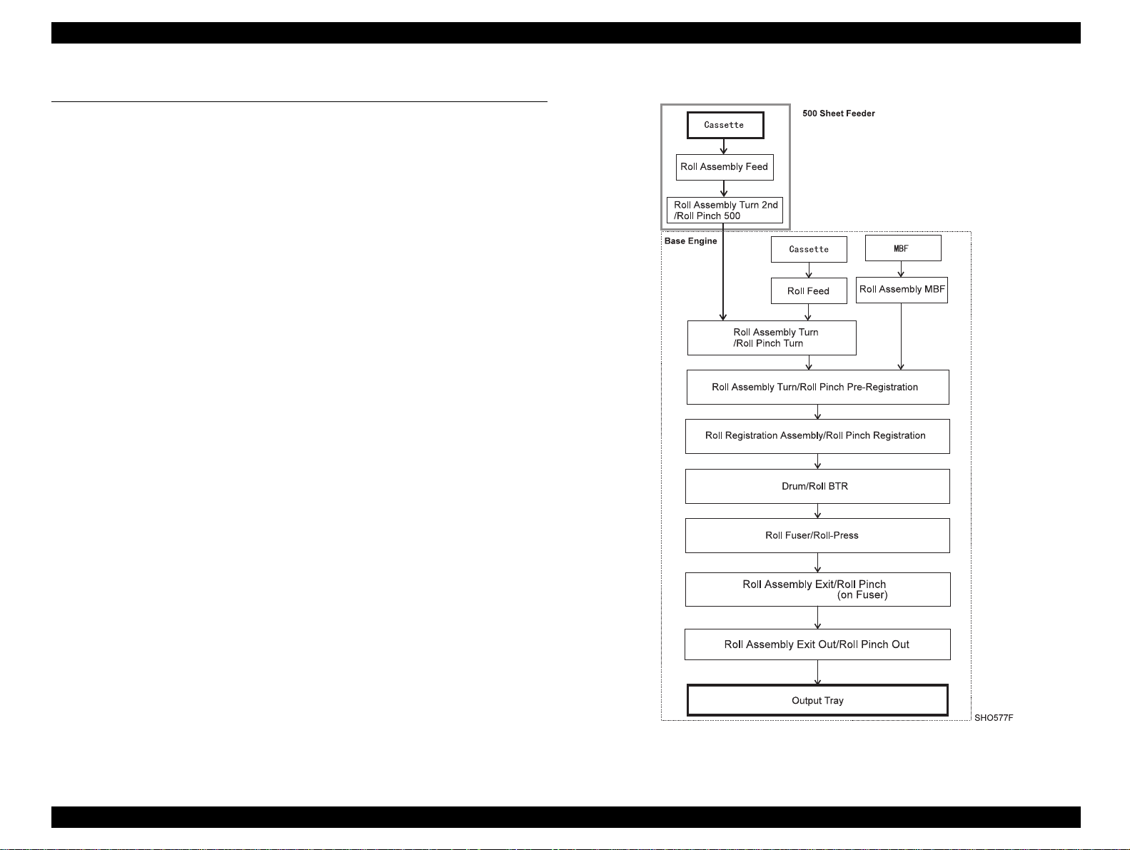
2.1.1 Paper Transportation
Paper that is fed from the 500 Sheet Feeder is transported through the
printer alon
the paper path shown in the Figure right.
Figure 2-1. Paper Path
Rev. 0 10
Page 11

EPSON EPL-N1600/500 Sheets Feeder Chapter 2 OPERATING PRINCIPLES
The Figure below is a cut-away side view of the EPL-N1600 with the
optional 500 Sheet Feeder attached that shows the paper paths and the
major components directly related to the paper transportation.
Figure 2-2. 500 Sheet Feeder Paper Path
Rev. 0 11
Page 12

EPSON EPL-N1600/500 Sheets Feeder Chapter 2 OPERATING PRINCIPLES
g
g
2.1.2 Drive Power Transmission
The drive power to operate the 500 Sheet Feeder is supplied by the
Paper Handlin
Motor of the Base Engine through the Drive Assembly.
The fi
Feeder.
ure below shows the drive power transmission to 500 Sheet
Figure 2-3. 500 Sheet Feeder Drive Power Transmission
Figure 2-4. Drive Power Transmission
Rev. 0 12
Page 13

EPSON EPL-N1600/500 Sheets Feeder Chapter 2 OPERATING PRINCIPLES
g
g
g
g
g
g
g
g
g
g
g
g
g
gag
g
g
g
2.1.3 Function of Major Components
500 Sheet Universal CassetteUniversal paper cassette that holds 500
plain paper cut sheets of various re
sizes. You adjust the Cassette Guides to
accommodate different paper siz es. Adjustin
the Back Guide chan
Actuators that are located alon
of the cassette. When the cassette with paper
loaded is installed in the Feeder, the
Actuators press a
es the position of the
ainst the Size Spring.
ular
the left side
PWB Assembly Size 500 A Sprin
Switches, and the No-Paper Sensor are
mounted on the Size PWB.
Spring CST Act:
Actuators on the side of the Paper Cassette
press a
in turn press a
Paper Size Switches:
when the correspondin
ainst it, and Off when the corresponding
a
sprin
combination of On and Off Size Switches
represents the size o the paper that i s loaded
in the Cassette.
No Paper Senso
is empty, the Actuator No Paper 500 actuates
the No Paper Sensor.
Sprin
Solenoid Pick-Up Releases the Gear Feed to allow i t to en
Roll Assembly Feed Is a D-shaped roll that is driven to rotate one
CST Latch Secures the 500 Sheet Feeder in place in the
Feeder.
with the drive
actuated, and latches the Feed Gear after
one turn. This causes the Roll Assembly
Feed to rotate one turn.
turn each time the Solenoid Pick Up is
actuated.
CST Act, three Paper Size
has three pron
ainst individual prongs. Each prong
ainst a Paper Size Switch.
A Size Switch is On
spring prong presses
prong does not press against it. The
r: When the Paper Cassett e
ear and rotate one turn when
s. The
e
Envelope/Postcard CassetteHolds standard envelopes and postcards.
See Section 16 500 Sheet Feeder
Specification.
Roll Assembly Turn 2nd Transports, alon
located in the Cassette, paper out of the
Cassette into the Base En
with the Roll Pinch that is
ine paper path.
Rev. 0 13
Page 14

EPSON EPL-N1600/500 Sheets Feeder Chapter 2 OPERATING PRINCIPLES
g
g
g
2.1.4 Paper Jam Detection
A paper jam between the 500 Sheet Feeder and the Sensor Pre-
istration (Misfeed jam) is detec ted usi ng the E
re
is a time interval from Solenoid Pick-Up actuation to Sensor Pre-
istration actuation. If the paper fed fr om the 500 Sheet Feeder do not
re
actuate the Sensor Pre-re
istration within this time interval, the MCU
interprets that a Misfeed jam has occurred and displays Error (Feed
jam).
time. The E
2-1
2-1
time
The E
time for the 500 Sheet Feeder (cassette 2) is 2.036 seconds.
2-1
Rev. 0 14
Page 15

TROUBLESHOOTING
Page 16

EPSON EPL-N1600/500 Sheets Feeder Chapter 3 TROUBLESHOOTING
This chapter is not applicable to the 500 sheets Feeder.
Rev. 0 16
Page 17

DISASSEMBLY AND ASSEMBLY
Page 18

EPSON EPL-N1600/500 Sheets Feeder Chapter 4 DISASSEMBLY AND ASSEMBLY
ging
4.1 OVERVIEW
This section contains the removal and replacement procedures of major
parts or subsystems within optional Feeder Assembly 500 of the EPLN1600.
4.1.1 Precautions
Be sure to carry out all work in accordance with the precautions
provided below to avoid dama
assembly.
CAUTION
Names of parts that appear in this chapter may not be
exactly the same as the name appears in Parts List.
For example, Roll Assembly Exit on the Parts List
may appear as Roll Exit or Exit Roll in the RRPs, so
far as it does not cause confusion. This is because of
readability or conventions.
Always use correct type and size screws. Using a
wrong screw can damage a tapped hole. Do not overtighten screws.
Do not use excessive force to either remove or instal l
a part.
the unit during disassembly and
4.1.2 Tools
The following table lists the tools you need to disassemble and
reassemble the printer.
Table 4-1. Required Tools
Market
Tool
Phillips screwdriver Yes B743800200
Tweezers Yes B641000100
Round nose pliers Yes B740400100
Availability
Code
Rev. 0 18
Page 19

EPSON EPL-N1600/500 Sheets Feeder Chapter 4 DISASSEMBLY AND ASSEMBLY
g
g
g
g
g
g
4.1.3 Removing Feeder Assembly 500
1. Disconnect the AC power cord to the rear of the printer.
2. Disconnect all interface Cables to the rear of the printer.
3. Remove the Paper Cassette from the Feeder Assembly 500.
4. Remove the 250 Sheet Paper Cassette (2). Remove the Duplex
Chute Cover Assembly (2), if optional Duplex Unit is instal led.
5. Press the Joint Feeder cli ps to
Feeder clips securin
Duplex Unit (1).
6. Press the Joint Feeder clips to
Feeder clips securin
Duplex Unit (3).
7. Lift the base en
Duplex Unit is installed, first lift the base en
Unit, then lift the Duplex Unit off of the Feeder Assembly 500.
the Feeder Assembly 500 to the printer or t he
the Feeder Assembly 500 to the printer or t he
ine off of the Feeder Assembly 500. If the optional
ether and remove the two rear Joint
ether and remove the two front Joint
ine off of the Duplex
Figure 4-1. Removing Feeder Assembly 500
Rev. 0 19
Page 20

EPSON EPL-N1600/500 Sheets Feeder Chapter 4 DISASSEMBLY AND ASSEMBLY
g
4.1.4 Frame 500 Removal
1. Remove the Feeder Assembly 500.
2. Remove the four screws that are securin
500 to the Frame 500.
3. Push up on the Actuator No Paper 500 and raise the Subassembly
off of the Frame 500.
4. Unhook the Solenoid Pick-Up wire harness fr om the harness clip.
5. Disconnect J322 on the Solenoid Pick-Up wire harness from the
PWB Assembly Size 500.
6. Remove the Frame Subassembly.
the Frame Subassembly
Figure 4-2. Frame 500 Removal
Rev. 0 20
Page 21

EPSON EPL-N1600/500 Sheets Feeder Chapter 4 DISASSEMBLY AND ASSEMBLY
g
4.1.5 Solenoid Pick-Up Removal
1. Remove the Feeder Assembly 500.
2. Remove the Frame 500.
3. Remove the one screw that is securin
Frame Subassembly 500.
4. Remove the Solenoid Pick-Up.
the Solenoid Pick-Up to the
Figure 4-3. Solenoid Pick-Up Removal
Rev. 0 21
Page 22

EPSON EPL-N1600/500 Sheets Feeder Chapter 4 DISASSEMBLY AND ASSEMBLY
g
g
g
4.1.6 Cover-L 500
1. Remove the Feeder Assembly 500.
2. Set the Feeder Assembly 500 on the ri
side).
3. Remove the two machine screws ( screws with a flan
the bottom of the Feeder, that secure Cover-L 500 to the Frame
500.
4. Remove the three self-tappin
Feeder, that secure Cover-L 500 to the Frame 500.
5. If the Paper Cassette is installed, remove it from the Feeder
Assembly 500.
6. Pull Cover-L 500 away from the Frame 500.
screws, located on the top of the
ht side (the Cover R 500
e), located on
Figure 4-4. Cover-L 500 Removal
Rev. 0 22
Page 23

EPSON EPL-N1600/500 Sheets Feeder Chapter 4 DISASSEMBLY AND ASSEMBLY
g
4.1.7 PWB Assembly Size 500 Removal
1. Remove the Feeder Assembly 500.
2. Remove the Cover-L 500.
3. Disconnect J302 from J292. Remove the two screws that secure the
connector J292 bracket to the Fra me 500, and cut the wire harness
(1).
4. Remove the two screws that secur e t he PWB Assemb ly Siz e 500 t o
the Frame 500.
5. Slide the PWBA Size out of the retainin
6. Remove the PWBA Size.
7. Disconnect J285 from the PWBA Size.
clips.
Figure 4-5. PWB Assembly Size 500 Removal
Rev. 0 23
Page 24

ADJUSTMENT
Page 25

EPSON EPL-N1600/500 Sheets Feeder Chapter 5 Adjustment
There is no specific adjustment required for 500 sheets feeder.
Rev. 0 26
Page 26

MAINTENANCE
Page 27

EPSON EPL-N1600/500 Sheets Feeder Chapter 6 Maintenance
No specific maintenance is required on the 500 Sheets Feeder.
Rev. 0 28
Page 28

APPENDIX
Page 29

EPSON EPL-N1600/500 Sheet Feeder Chapter 7 Appendix
y
y
y
y
y
7.1 Connector Location
Connector Location Harness
J292 E2
J302 E3
P/J322 E1
*1:"@" mark at the beginning of a harness name indicates that the subject harness is a
part of the component from where the harness extends.
Connects the 500 Sheet Feeder to the
PWB Assembl
Assembl
Connects the 500 Sheet Feeder to the
PWB Assembl
Assembl
Connects the Solenoid Pick-Up to the
PWB Assembl
-Size 1 or PWBA
Duplex.
-Size 1 or PWBA
Duplex.
Size 500.
Figure 7-1. Connector Location Diagram
Rev. 0 30
Page 30

EPSON EPL-N1600/500 Sheet Feeder Chapter 7 Appendix
g
g
g
7.2 Master Wiring Diagram
Signal names for the Base Engine or Duplex Unit ↔ PWB
Assembly Size 500 ↔ Solenoid Pick Up path
Signal Name Description
/SIZE2 Signal for indicating the detected size of paper in the Cassette in
Feeder 2. (Analo
NO PAPER Signal for monitoring paper in Feeder 2 (High when paper is
present and Low when paper is not present)
/FEED2 Si
nal for actuating the Solenoid feeding paper in Feeder 2.
value)
Pin numbers and voltage levels for the Base Engine or Duplex Unit
↔
PWB Assembly Size 500 ↔ Solenoid Pick-Up path
P242
or
P312
P282 Signal Name
6 9 SIZE2 M
510 NO PAPER2 M → S Level TTL TTL
1 14 /FEED2 M → S Level 24 V 0 V
Signal Direction
M: PWBA MMCU
S: PWBA Size 500 Trigger
←
S-**
High
Level
Low
Level
Relationship between paper sizes, pattern of actuated Paper
SizeSwitches, and voltage of the SIZE signal for 500 Sheet Feeder
Signal
Voltage
Paper Size SW1 SW2 SW3
Cassette not in place 0 0 0 0.45
Letter SEF 0 0 1 2.19
A4 SEF 0 1 1 2.82
Legal 13" 1 1 0 2.40
Le
al 14" 1 1 1 3.08
(VDC)
Figure 7-2. Wiring Diagram - 500 Sheets Feeder
Rev. 0 31
Page 31

EPSON EPL-N1600/500 Sheet Feeder Chapter 7 Appendix
g
g
g
g
g
7.3 Exploded Diagram
500 SHEET FEEDER (OPTIONAL)
1. Feeder Assembly 500 (with 2-19) $
2. Cover R 500
3. Frame 500
4. Sprin
5. Sprin
6. Cover-L 500
7. PWB Assembly Size 500 $
8. Sprin
9. Tie Bar 500
10. Actuator No Paper 500
CST Latch
CST Act
-Earth Feeder
18. Roll Assembly Turn 2nd
19. Connector
20. Envelope/Postcard Cassette
21. 500 Sheet Universal Cassette
22. Joint Feeder (PL10.1.8) $
11. Guide
12. Frame Subassembly 500 (with 13-18) $
13. Solenoid Pick-Up (PL3.1.14) $
14. Sprin
15. Support Sprin
16. Roll Assembly Feed
17. Plate N/P
Feed 500
Feed
Rev. 0 32
Page 32

 Loading...