

Page 1

EPSON TERM
EPL-3000
NAL PR NTER
ActionLaser
1300
SERVICE MANUAL
EPSON
Page 2

NOTICE
All rights reserved. Reproduction of any part of this manual in any form whatsoever without
SEIKO EPSON’s express written permission is forbidden.
The contents of this manual are subjects to change without notice.
All efforts have been made to ensure the accuracy of the contents of this manual. However, should
any errors be detected, SEIKO EPSON would greatly appreciate being informed of them.
The above notwithstanding SEIKO EPSON can assume no responsibility for any errors in this
manual or the consequence thereof.
Epson is registered trademark of Seiko Epson Corporation.
General Notice: Other product names used herein are for identication purposes only and maybe
trademarks of their respective campanies.
Copyright @ 1994 by SEIKO EPSON CORPORATION Nagano, Japan
t
!
G’ i
-i-
Page 3
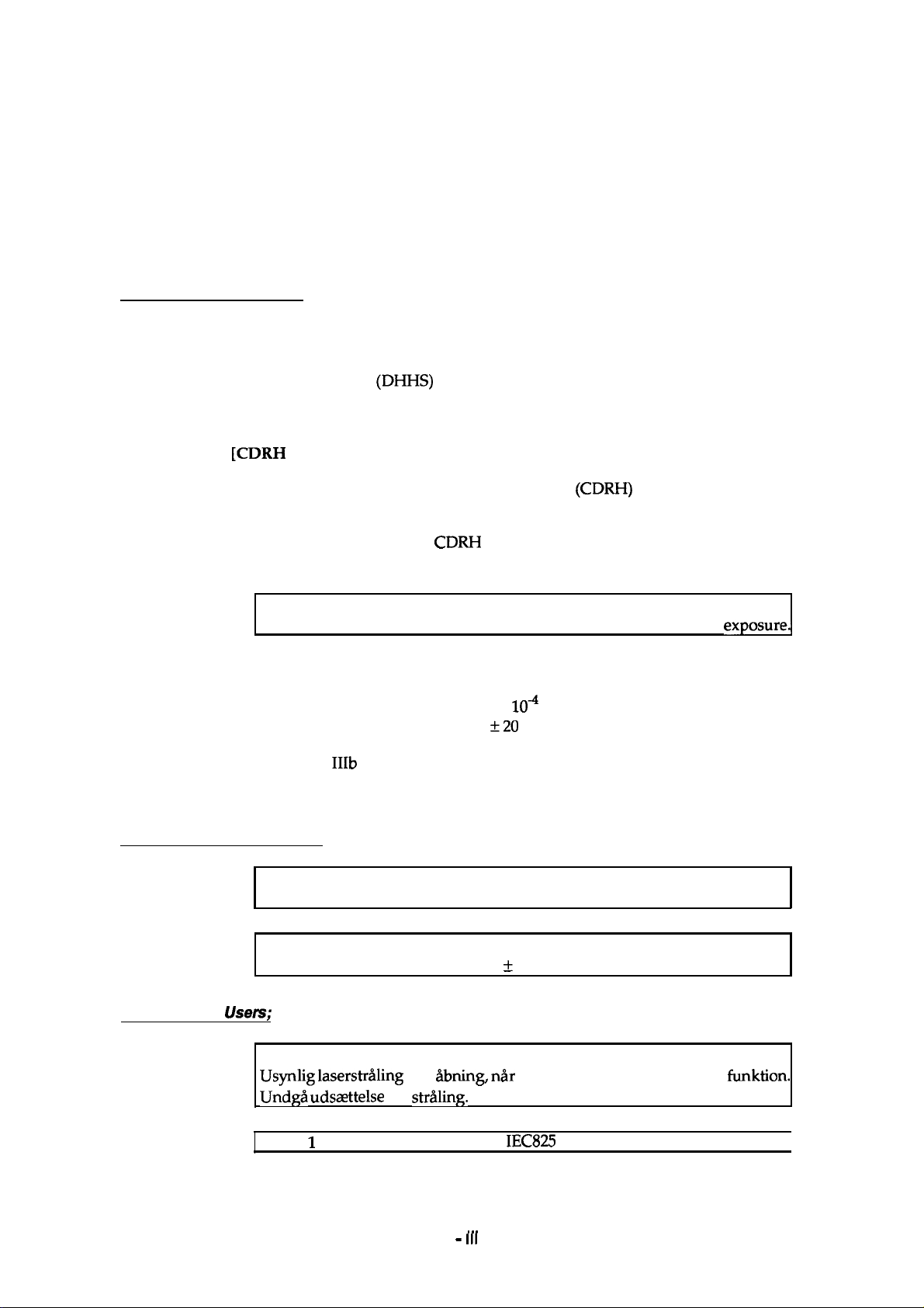
SAFETY INFORMATION
This printer is a page printer which operates by means of a laser. There is no possibility of danger from
the laser, provided the printer is operated according to the instructions in this manual provided.
Since radiation emitted by the laser is completely confined within protective housings, the laser beam
cannot escape from the machine during any phase of user operation.
For United States Users;
[Laser Safety]
This printer is certified as a Class 1 Laser product under the U.S. Department of Health
and Human Services
tion Control for Health and Safety Act of 1968. This means that the printer does not
produce hazardous laser radiation.
[CDRH Regulations]
(DHHS)
Radiation Performance Standard according to the Radia-
The Center for Devices and Radiological Health
Administration implemented regulations for laser products on August 2,1976. Compliance is mandatory for products marketed in the United States. The label shown below
indicates compliance with the
marketed in the United States.
WARNING: Use of controls, adjustments or performance of procedures other
thanthosespecified in this manual may result in hazardous radiation
[Internal Laser Radiation]
Maximum Radiation Power:
Wave Length:
This is a Class
unit is NOT A FIELD SERVICE ITEM. Therefore, the print head unit should not be
opened under any circumstances.
For Other Countries Users;
WARNING: Use of controls, adjustments or performance of procedures other
than those specified in this manual may result in hazardous radiation exposure.
(CDRH)
CDRH
regulations and must be attached to laser products
1OA
3.025 X
*20
780
IIIb Laser Diode Assay that has an invisible laser beam. The print head
(W)
nm
of the U.S. Food and Drug
exposurel
For Denmark
This is a semiconductor laser. The maximum power of the laser diode is 3.025
4
W and the wavelen
x 10
gth is 780
f
20 nm.
Usem;
ADVARSEL
Usynlig
Undgi?i
Klasse
laserstr~ling
udszttelse for
1
laser produkt der opfy
ved
iibning, ni%
strtiling.
lder
. . .
- Ill -
sikkerhedsafbrydere er ude af
IEC825
sikkerheds kravene.
funktion.
I
Page 4
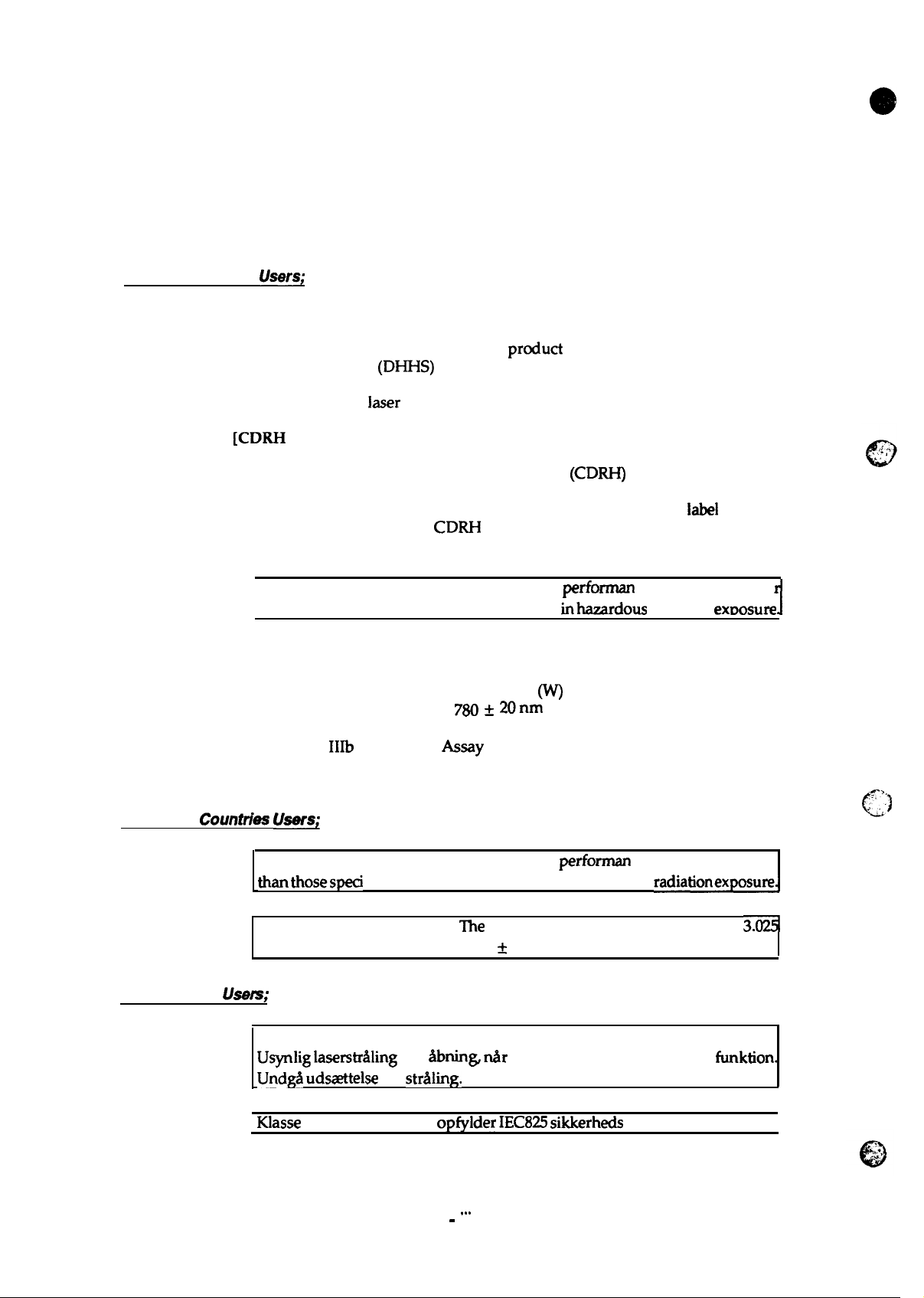
SAFETY INFORMATION
This printer is a page printer which operates by means of a laser. There is no possibility of danger from
the laser, provided the printer is operated according to the instructions in this manual provided.
Since radiation emitted by the laser is completely confined within protective housings, the laser beam
cannot escape from the machine during any phase of user operation.
For United Slates
[Laser Safety]
This printer is certified as a Class 1 Laser
and Human Services (DHHS) Radiation Perfo
tion Control for Health and Safety Act of 1968. This means that the printer does not
produce hazardous
[CDRH Regulations]
The Center for Devices and Radiological Health
Administration implemented regulations for laser products on August 2,1976. Compliance is mandatory for products marketed in the United States. The
indicates compliance with the
marketed in the United States.
I
[Internal Laser Radiation]
Maximum Radiation Power:
Wave Length:
Users;
prcduct under the U.S. Department of Health
rmance Standard according to the Radia-
laser radiation.
CDRH
WARNING: Use of controls, adjustments or
thanthosesoecified in this manual mav result
regulations and must be attached tolaserproducts
4
3.025X 10
780 + 20nm
(w)
(CDRH)
performan
inhaardous
of the U.S. Food and Drug
label
shown below
ceof procedures othe
radiation exDosure
1
This is a Class
unit is NOT A FIELD SERVICE ITEM. Therefore, the print head unit should not be
opened under any circumstances.
For Other Coun&ks
WARNING: Use of controls, adjustments or
thanthosespeci
This is a semiconductor laser.
x 10
For Denmark
Usem;
ADVARSEL
Usynlig laserstdling ved
Undgi% udszettelse
Klasse 1 laser produkt der opfylder
IIIb
Laser Diode
Users;
“fied in this manual may result in hazardous radiationexposurel
4
Wand the wavelength
for
&say
&mins &r
str?ding.
that has. an invisible laser beam. The print head
perforrnance of procedures other
The
maximum power of the laser diode is 3.(X#
is 780 f 20 nm.
sikkerhedsafbrydere er ude af
IEC825
sikkerheds kravene.
funktion.
.- ,.
.. ,.,
”
~)
I
-
Ill -
. . .
Page 5
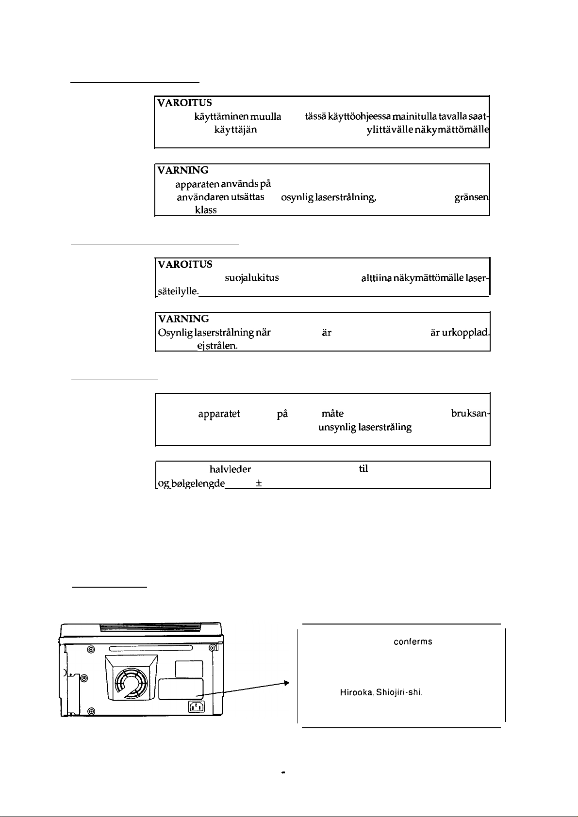
For Finland, Sweden Users;
VAROITUS
Laitteen
taa altistaa kayttajan turvallisuusluokan 1 ylittavalle nakymattomalle
lasersateiylle.
VARNING
Om
kan
for laser klass 1.
kiiyttaminen muulla
apparaten
anviindaren
anviinds pa
utsattas for osynlig
For Finland, Sweden Service People
VAROITUS
Avattaessa ja
sateilylle.
VARNING
Osynlig laserstrNning
Betrakta ej
suojalukitus ohitettaessa olet
Ala katso sateeseen.
stri?den.
kuin
tiissii lciiyttoohjeessa mainitulla tavalla saat-
annat satt an i denna bruksanvisning specificerats,
laserstriNnin&
niir
denna del ar oppnad och sparren ar
som overskrider
alttiina nakymattorrkille laser-
urkopplad.
gransen
For Norway Users;
ADVARSEL
Dersom
visning, kan brukeren utsettes for unsynlig
grensen for laser klasse 1.
Dette er en
og bolgelengde er 780 * 20 nm.
apparatet brukes
halvleder laser. Maksimal effeckt
pii
annen
rni%e
em spesifisert i denne
laserstr~ling
til
laserdiode er 3.025 x 10
Laser Safety Labels
[Label on rear printer case]
A laser safety labels is attached on the outside of the printer shown below.
For United State
This laser product conferms to the
applicable requirement of 21
Chapter 1, subchapter J.
SEIKO EPSON CORP.
Hirooka Office
80
Hirooka, Shiojiri-shi,
JAPAN
MANUFACTURED:
bruksan-
som overskrider
-4
W
CFR
Nagano-ken,
-
iv -
Page 6
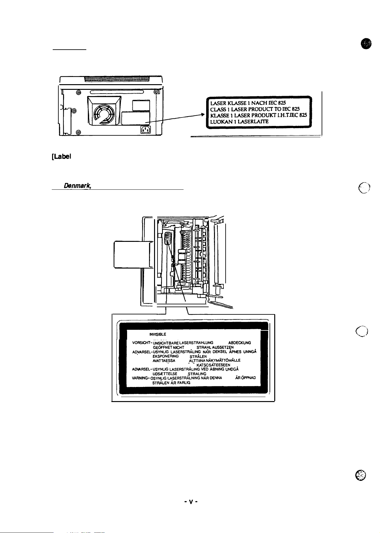
For Europa
[Lsbel
inside printer]
The following laser safety label will be attached inside the printer as shown below.
For
Danmark,
Finland, Swadan, and Norway
I
\
I
CAUTION-
NVISISLE
IB
VORSICHT- U”iJSICNTBARE LASERSTRAHLUNG
AOYARSEL-USYNLIG
VARO !
AOVARSEL-USYNIJG
VARNING- OSYNLIG
I
LASER RADIATION WHEN OPEN AVOID
EXPOSURE TO BEAM
GE6FFNET NICNT
EKSPONERING
AVATTAESSA
LASERSATEILYLLE ALA
uD.9ETTELSE
LASERSTRiLNING
STF&LEN AR FARLIG
I
DEM
LASERSTRiLlffi
FOR
OLET
LASERSTtiLING
FOR
1%
WENN
STRA~L AUSSSTZEN
NAR OEKSEL hJES U*
STRdLEN
-A~TTllNA
N~KYMiTT6M~LLE
KATSO S.ATEESEEN
VED ABNING
STf7ALlNG
NAR OENNA
“)
C..
.
I
-..,
(J
ABOECKUNG
UNDG/i
OEL h I%WAD
-v-
Page 7

PREFACE
This manual describes functions, theory of electrical and mechanical operations, maintenance, and repair
of EPL-3000/ActionLaser
The instructions and procedures included herein are intended for the experience repair technician, and
attention should be given to the precautions on the preceding page. The chapters are
follows:
CHAPTER 1. GENERAL DESCRIPTION
Provides a general product overview, lists
CHAPTER 2. OPERATING PRINCIPLES
Describes the theory of printer operation.
CHAPTER 3. DISASSEMBLY AND ASSEMBLY
Includes a step-by-step guide for product disassembly and assembly.
CHAPTER 4. ADJUSTMENT
Includes a step-by-step guide for
CHAPTER 5. TROUBLESHOOTING
Provides Epson-approved techniques for adjustment.
1300.
adjustmen~
speeitications,
and illustrates the
main components
of the printer.
organizd
as
CHAPTER 6. MAINTENANCE
Describes preventive maintenance techniques and lists lubricants and adhesives required to service the equipment.
APPENDIX
Describes connector pin assignments, circuit diagrams, circuit board component layout and exploded diagram.
The contents of this manual are subject to change without notice.
- vi -
Page 8
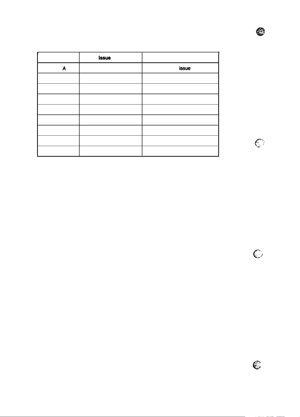
REVISION SHEET
t
Revision
Rev.
A
laeue
Date
July 22,1994
Revision Page
let
iesue
T
- vii -
5.
..
.
‘i
C“
Page 9

TABLE OF CONTENTS
CHAPTER 1.
CHAPTER 2.
CHAPTER 3.
CHAPTER 4.
CHAPTER 5.
CHAPTER 6.
APPENDIX
GENERAL DESCRIPTION
OPERATING PRINCIPLES
DISASSEMBLY AND ASSEMBLY
ADJUSTMENT
TROUBLESHOOTING
MAINTENANCE
-
. . .
Vlll
-
Page 10
Chapter 1
General Description
Table of Contents
1.1
FEATURES
1.2 SPECIFICATIONS
1.2.1
1.2.2
1.2.3
1.2.4
1.2.5
1.2.6
1.2.7
1.2.8
1.2.9
1.3 INTERFACE SPECIFICATIONS
1.3.1
1.3.2 Optional Interface C82305*/C82306* (EPL-3000 only) . . . . . . . . . . . . . 1-15
Basic Specifications. . . . . . . . . . . . . . . . . . . . . . . . . . . . . . . . . . . . . . . . .
Electrical Specifications. . . . . . . . . . . . . . . . . . . . . . . . . . . . . . . . . . . . . .
Reliability Specifications . . . . . . . . . . . . . . . . . . . . . . . . . . . . . . . . . . . . .
Environmental Conditions for Operation (Including Imaging Cartridge). . 1-5
Environmental Conditions for Storage and Transportation
(Excluding Image Cartridge) . . . . . . . . . . . . . . . . . . . . . . . . . . . . . . . . . .
Applicable Standards. . . . . . . . . . . . . . . . . . . . . . . . . . . . . . . . . . . . . . . .
Consumable (Imaging Cartridge) Specifications . . . . . . . . . . . . . . . . . . .
Physical Specifications . . . . . . . . . . . . . . . . . . . . . . . . . . . . . . . . . . . . . .
Software Specifications. . . . . . . . . . . . . . . . . . . . . . . . . . . . . . . . . . . . . .
Parailellnterface.
1.3.1.1 Compatibility lvlodeof Parallel Interface. . . . . . . . . . . . . . . . . . .
1.3.1.2 Reverse Mode... . . . . . . . . . . . . . . . . . . . . . . . . . . . . . . . . . . .
. . . . . . . . . . . . . . . . . . . . . . . . . . . . . . . . . . . . . . . . . .
1.4 OPERATING INSTRUCTIONS
1.4.1
1.4.2
1.4.3
1.4.4
1.4.5
1.4.6
1.4.7
1.4.8
Control Panel. . . . . . . . . . . . . . . . . . . . . . . . . . . . . . . . . . . . . . . . . . . . .
Service Mode. . . . . . . . . . . . . . . . . . . . . . . . . . . . . . . . . . . . . . . . . . . . .
1.4.3.1 Hexadecimal Dump Mode. . . . . . . . . . . . . . . . . . . . . . . . . . . . .
1.4.3.2 Factory Service Mode. . . . . . . . . . . . . . . . . . . . . . . . . . . . . . . .
1.4.3.3 EEPROM Format Mode . . . . . . . . . . . . . . . . . . . . . . . . . . . . . .
Message Display. . . . . . . . . . . . . . . . . . . . . . . . . . . . . . . . . . . . . . . . . .
1.4.3.1 Status and Error Messages. . . . . . . . . . . . . . . . . . . . . . . . . . . .
1.4.3.2
Printer Sharing. . . . . . . . . . . . . . . . . . . . . . . . . . . . . . . . . . . . . . . . . . . .
Emulation Mode Switch Function . . . . . . . . . . . . . . . . . . . . . . . . . . . . .
1.4.5.1 Emulation Switch by SPL . . . . . . . . . . . . . . . . . . . . . . . . . . . . .
1.4.5.2 Intelligent Emulation Switch . . . . . . . . . . . . . . . . . . . . . . . . . . .
Resolution Improvement Technology . . . . . . . . . . . . . . . . . . . . . . . . . .
Toner Save Mode . . . . . . . . . . . . . . . . . . . . . . . . . . . . . . . . . . . . . . . . .
Optional Memory. . . . . . . . . . . . . . . . . . . . . . . . . . . . . . . . . . . . . . . . . .
SewiceCall
Error . . . . . . . . . . . . . . . . . . . . . . . . . . . . . . . . . . .
1-1
1-3
.-
l-~
1-5
1-5
1-5
1-6
1-6
1-6
1-7
1-9
1-9
1-9
1-11
1-16
1-16
1-17
1-17
1-17
1-17
1-18
1-18
1-19
1-20
1-20
1-20
1-21
1-21
1-22
1-22
1.5 MAIN COMPONENTS
1.5.1 C144 MAIN Board. . . . . . . . . . . . . . . . . . . . . . . . . . . . . . . . . . . . . . . . .
1.5.2 ROM SIMM Board . . . . . . . . . . . . . . . . . . . . . . . . . . . . . . . . . . . . . . . .
1.5.3
1.5.4
PWB-E
PWB-F
Board . . . . . . . . . . . . . . . . . . . . . . . . . . . . . . . . . . . . . . . . . . . .
Board . . . . . . . . . . . . . . . . . . . . . . . . . . . . . . . . . . . . . . . . . . . .
1.5.5 Optical Unit . . . . . . . . . . . . . . . . . . . . . . . . . . . . . . . . . . . . . . . . . . . . . .
1.5.8 Fusing Unit . . . . . . . . . . . . . . . . . . . . . . . . . . . . . . . . . . . . . . . . . . . . . .
1.5.9 Drive Unit. . . . . . . . . . . . . . . . . . . . . . . . . . . . . . . . . . . . . . . .
1.5.10
Imaging Cartridge . . . . . . . . . . . . . . . . . . . . . . . . . . . . . . . . . . . . . . .
........
1-23
1-24
1-25
1-25
1-26
1-26
1-27
1-27
. 1-27
Page 11

EPL-3000
1.1
The EPSON@ EPL-3000
semi-conductor laser with
feature high-speed, high-resolution printing. Maintenance is very easy because of various built-in
diagnostic functions. The main features are:
c1
Ct
cl
c1
c1
Q
c1
D
a
c1
c1
c1
Q
c1
c1
c1
c1
c1
/ActionLaser 1300
Sewice
Manual
FEATURES
and the ActionLaser
electro-photographic technology. These printers are small and light, and
No
ozone
Printing speed — 4 ppm (pages per minute)
Resolution — 300 dpi (dots per inch)
Light weight — about 7 kg (15 lb.)
Small footprint
Easy maintenance
@
LaserJet@
HP
22 built-in scalable fonts (8
Resolution Improvement Technology
edges from images and characters.
levels
Two
Optional
Optional WPS (Windows Printing System) SIMM module
1 MB standard RAM and up to 5 MB RAM with the addition of optional SIMM
Bidirectional parallel interface
High-speed parallel communication rate of approximately 125 KB/second
A multi-user, multi-emulation mode
IES (Intelligent Emulation Switch) allows switching between EPSONScript mode and
emulation mode.
SPL (Shared Printer Language) enables switching of the printer mode by command.
4L emulation mode
Agfa@
and 14 TrueType fonts)
(35~o
less
and
50~0
less) for Toner
EPSONScript Level 2 (PostScript@ compatible) SIMM module
TM
(PCL@5e
(RITech)
(EPL-3000)
1300 are non-impact page printers that combine a
emulation)
refines the print quality by eliminating jagged
Save
Mode
General Description
PCL5e
Figure 1-1 shows an exterior view of the
Paper support
(Paper
suppoti\extenSiOn)
cover
\
-
, ,-. . . .
.
Ac
mleT
i-usel
EPL-3000
and ActionLaser 1300.
. Latch
J“---+!n!?!
-B%&R1
.
Power
Switchl
\w//
Parallel
interface
/ cover
~
l\
%
\
,
Control
panel
Rev.
Imaging
cartridge
T
Figure 1-1. Exterior View of the
and
ActionLaser
1300
paper guides
EPL-3000
A
\
Front cover
1-1
Page 12
General
Description
EPL~(M/ActionLaser 13W
Service
Umue!
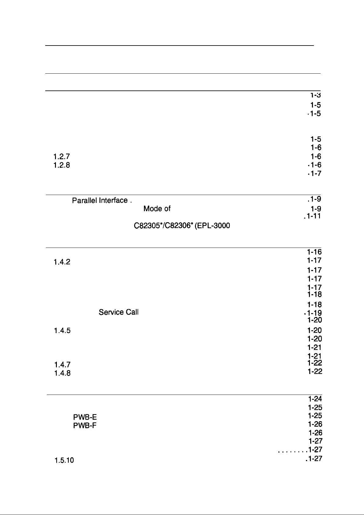
Table 1-1 lists the optional units avaiiable tbr the
Cat. No.
C83212*
283213*
—
—
—
3051020
:::::$
Table 1-1. Options for
Description
EPSONScript
Module
AWPS SIMM Module
Bitmap Local Language Font
ROM Chip
Scalable Local Language Font Supports scalable local
ROM Chip
Thai Font ROM Chip
Imaging cartridge
Serial interface
Level 2 SIMM
card
EPL-3000
EPL-3000
Supports
Level 2 mode (PostScript
Level 2
commands
Supports AtWork Printing
System
SUWRS
language fonts
language fonts
Suppotis
Toner cartridge Yes
—
and ActionLaser 1300.
and
ActionLaser
Note
EPSONScript
mmpatible)
bitmap
Thai fonts
fonts and
local
1300
I
MachineType
EPL3000
Yes
Yes Yes
Yes
Yes
Yes
Yes
Action
y6&
Yes
No
No
No
Yea
No
&
.. . . . ;
c?
>82307W
282308X
28231 OW
28231 1X
282312X I LocalTalkcard
28231 4X
28231 5*
Notes:
1. These printers can use only one optional ROM SIMM module.
2. The
3. The
EPL-3M10can
ActionLaser 1300 has not optional Type-B interface card slot.
32 KB serial interface card
32 KB parallel interface
COAX interface card
TWINAX interface card
useonlyoneoptional ROMchip.
cad
—
—
—
—
—
Yes
Yes
Yes I No
Yes
Yes
No
No
No
No
.’. : --
-,.,.
0
$
1-2
Rev.
,,
@
A
Page 13

EPL-3000/ActionLaser
1300 Service Manual
1.2 SPECIFICATIONS
This section provides statistical data for the EPL-3000 and ActionLaser 1300.
1.2.1 Basic Specifications
Printing method:
Resolution:
Printing speed:
First printing time (A4/LT): Less than30 seconds
Warm-up time:
Paper supply:
Laser beam scanning and dry electro-photography
300 dpi
4 ppm
Less than 40 seconds
(at rated current and 23‘C (73
See Table 1-2.
(letter/A4)
0
F) temperature)
Table 1-2. Paper Feed Methods
General Description
Paper Supply
Standard built-in
paper tray
Auto feed
Manual feed
Capacity
(20 lb. (70
paper
150
5 to
10
1
/m2)
Y
Paper Size
A5, B5, A4, LT,
GLT,
EXE, LG,
GLG, F4, HLT
Monarch,
DL, C5, C6,
Commercial-10
Any size feedable 16 to 42 lb.
(Note 2)
Usage Thickness
(Ream Weight)
16 to 24 lb.
(60 to 90
Envelopes made
IB5
of 16 to 24 lb. (60
to 90
(60 to 157
g/m2)
g/m2)
paper
g/m2)
Notes:
1. The weight inpounds (lb.) is determined by how much 500 sheets cut to 17 x 22 inches would
weigh;
2. Paper size range: width
Paper types:
l-g/mz= 0.2659763 lb.
length
See Table 1-3.
3.0 to 8.5 inches (76.2 to 216 mm)
5.0 to 14.0 inches
(127 to 356 mm)
Table 1-3. Paper Types
Xerox@
Standard paper
Normal paper
Special paper
20 lb. (75
4024 DP paper
g/m2)
Regular photocopier paper
Bond paper
Recycled paper
16 to 24 lb. (60 to 90
Card stock (90 to 157
g/m2)
g/m2)
Envelopes
Labels
Letterhead
Transparency
(OHP)
sheets
Colored paper
Rev. A
1-3
Page 14
General Description
EPL4000/ActionLaser 1300 Service
h#imual
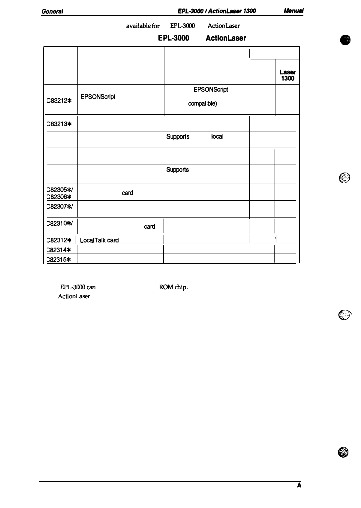
Usability of special paper:
Table 1-4.
Input
Standard
built-in paper Face down
tray
R: Reliable feeding and good
P: Possible, but better avoided.
N: Not supported.
Paper feed alignment and direction:
Paper ejection:
Output tray capacity:
Printable area (standard paper):
output
OHP Envelopes
image quality.
See Table 1-4.
Uaability
P
Center alignment for all sizes
Face down
50 sheets (standard paper)
See Figure 1-2.
of Special Paper
P
Labels
P P
—
i
Card Stock
4.Omm
Letterhead
R
0
Note:
Noise:
Ozone density:
Toxicity:
The
—
Printable
I
Areii
4.Omm
Figure 1-2. Printable Area
actual printable area depends on the printer mode.
dB(A)
dB(A)
(standby)
(operating)
Less than 30
Less than 47
Less than 0.01 ppm
No toxicity exists in organic photo conductor
or plastic materials
—
—
4.Omm
i
4
(OPC),
c’
toner,
1-4
Rev.
,.
.!
0
A
Page 15
EPL-3000 /ActionLaser
1300 Service Manual
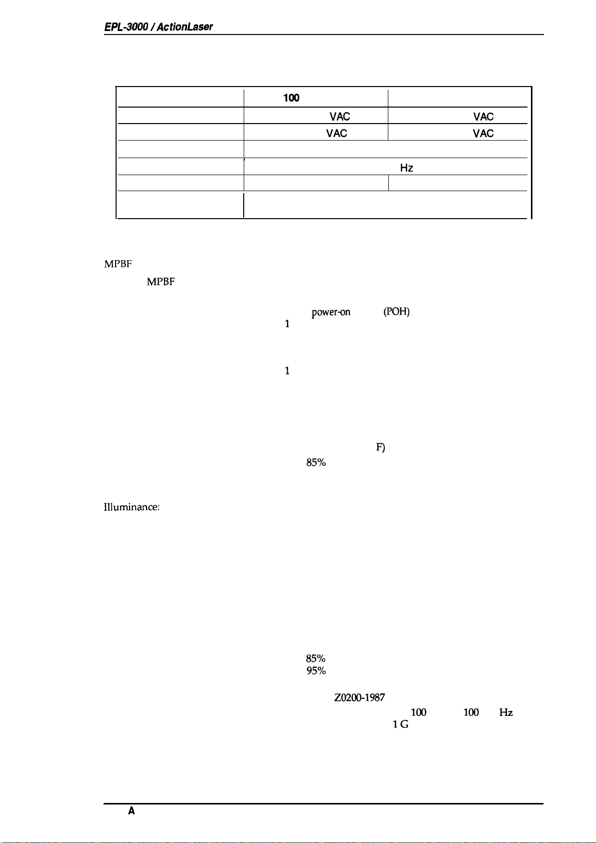
1.2.2 Electrical Specifications
Table 1-5. Electrical Specifications
Description
lMl
V Version
General Description
200 V Version
Rated
Input voltage range
Rated frequency range
Input frequency range
Power consumption
Power consumption while
in standby mode
voltage
100-120
90-132
I
Less than 350 W
1.2.3 Reliability Specifications
MPBF
(Mean Prints Between Failures): Over 17,000 sheets
Note:
MTBF (Mean Time Between Failures):
Jam rate:
Feed failure:
Multiple paper feeds:
Paper curl height:
Leading edge bending (1 cm or more):
MTTR (Mean Time To Repair):
Durability:
MPBF indicates the average number of pages printed before the occurrence of a problem
requiring replacement or service.
3000 power-n hours
1
out of 2,000 sheets or less (excluding multiple-sheet feeding)
1 out of 2,000 sheets or less (excluding multiple-sheet feeding)
1 out of 500 sheets or less
30 mm (1.2 inches) or less
1
out of 1,000 sheets
30
minutes or less
5 years or 100,0000 sheets
VAC
VAC
Less than 15 W
50-60 Hz
47-63
tiz
(POH)
220-240
198-264
Less than 450 W
VAC
VAC
1.2.4 Environmental Conditions for Operation (Including Imaging Cartridge)
Temperature:
Humidity:
Altitude:
Horizontal placement:
Illuminance:
Surrounding space:
10 to 35° c (50 to 95°
8570
15 to
2,500 m (8,200 feet) or lower
The printer should be installed on a level plane.
3,000 IUX or less (must not be exposed to direct sunlight)
The printer should have at least 100 mm of clearance on its
sides and rear.
RH
F)
1.2.5 Environmental Conditions for Storage and Transportation
(Excluding Imaging Cartridge)
Temperature:
Humidity: 30 to
Drop test:
Vibration:
Resistance to atmospheric pressure:
Storage term:
O to 35° C (32 to 95° F) over full storage term
-20 to 55° C (-4 to 131° F) under extreme conditions
(Extremes are allowable for up to 1/30 of full storage term)
Temperature variation must be 10” C (18° F)/hour or less
857. RH over full storage term
%~.
10 to
(Extremes are allowable for up to 1/30 of full storage term)
Clear to JIS Z0200-1987 Level 1
Vibration frequency
Acceleration
Acceleration direction 3 direction
More than 613 hPa
24 months (following date of manufacture)
RH under extreme conditions
5 to
100
Hz and
IG
100
to 5
Hz
Rev.
A
1-5
Page 16
General Description
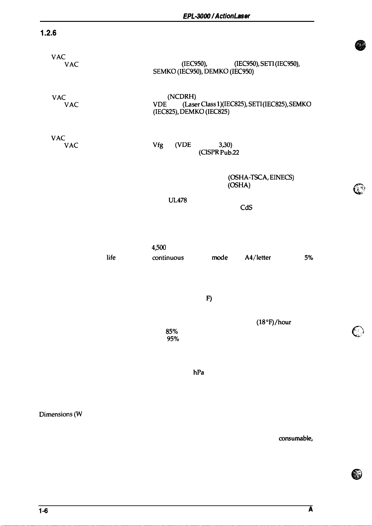
1.2.6
Applicable Standards
EPL+OtUllActionLaser 1300 Service Manual
Safety
120
220/240
Standards
VAC
model:
VAC
model:
UL 1950, CSA 22.2 No.950 Deviation 3
EN 60950
SEMKO
Safety Regulations (Laser radiation)
120
VAC
220/240
model:
VAC model:
FDA (NCDRH) Class 1
VDE 0837 (Laser Class
(IEC825),
EMI
120
VAC
220/240
model:
VAC
model:
FCC Part 15 Subpart B Class B
Vfg 243 (VDE 0878 Part
EN55022 class B (CISPR
Others
Toner:
OPC:
Ozone:
Materials:
No effect on human health
No effect on human health
Less than 0.01 mmp
other
SWISS Environmental Law (No
(IEC950),
DEMKO
UL478
(IEC950),
(5th edition)
NEMKO
DEMKO
(IEC825)
(IEC950),
(IEC950)
1)(IEC825), SETI (IEC825), SEMKO
3s0)
Pub.22
class B)
(OSHA-TSCA,
(OSHA)
SETI
(IEC950),
EINECS)
CdS must be contained)
“’$”::,
.
c
“)
1.2.7 Consumable (Imaging Cartridge) Specifications
Life:
Note:
Consumable
image ratio (black/white ratio). The life varies, depending on the printing mode
(continuous or intermittent) and/or the image ratio.
life
is based on
Environmental Conditions for Storage and Transportation
Temperature:
Humidity:
Drop test:
Vibration:
Resistance to atmospheric pressure:
Storage term:
3,000 pages (unit included with printer)
4300
pages (optional consumable)
COXItinUOtM
Oto300 C (32to860
–20 to40‘C (-4 to 104 “F) under extreme conditions
(Extremes are allowable for up to 1/.30 of full storage term)
Temperature variations must be10“C
30 to
10 to
(Extremes are allowable for up to 1/30 of full storage term)
Height 76 cm (30.4 inches)
Same as printer
More than 740
18 months (following date of manufacture)
printing mode with A4/letter paper at a
F’)
over full storage term
85Y0
RH over full storage term
%~o
RH under extreme conditions
hpa
1.2.8 Physical Specifications
(18 OF)/hour
5’%.
or less.
. .
. .
.
)
:..
..,
c
Dimensions(W x D x H):
Weight:
14
376 x 311 x 216 mm (14.8
376 x 444 x 218 mm (14.8 x 17.5x 8.9 inches) (paper
tray set)
Approximately 7 Kg (15.5 lb.) (including
excluding all options)
x 12.3x 8.5 inches)
cmsumable,
Rev.
,.
@
A
Page 17
EPL-3000
/ActionLaser 1300
Service
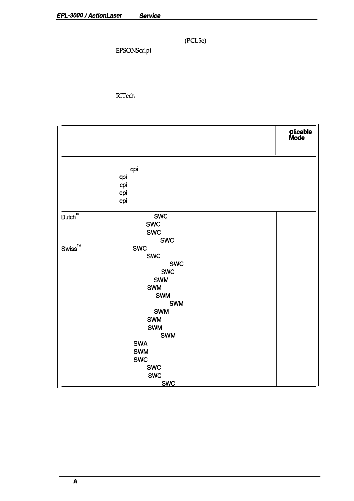
1.2.9 Software Specifications
Built-in modes:
Optional modes:
Auxiliary software:
Built-in fonts:
HP LaserJet 4L emulation
EPSONScript Level 2 (PostScript Level 2 emulation) mode
AWPS (AtWork Printing System) mode
Hex dump
Status sheet
Font sample
Fact sheet
RITech test sheet
See Table 1-6
Table 1-6. Built-in Fonts
Resident Fonts
Bitmap fonts
Line Printer
Courier
Courier Bold
Courier
Courier Bold
Scalable fonts
Dutch’”
801
Dutch 801
Dutch 801
Dutch 801
Swiss’” 742
Swiss 742
Swiss 742
Swiss 742
Swiss
721
Swiss
721
Swiss 721
Swiss 721
Dutch 801
Dutch 801
Dutch 801
Dutch 801
Symbol Set
More WingBats
Courier
Courier
Courier
Courier
16.66
10
10
12
12
cpi
(Portrait)
cpi
cpi
cpi
cpi
Roman
Bold
Italic
Bold Italic
Swc
Bold
Medium Italic
Bold Italic
Roman
Bold
Oblique
Bold Oblique
Roman
Bold
Italic
Bold Italic
SWA
SWM
Swc
Bold
Italic
Bold Italic
(Portrait)
(Portrait)
(Portrait)
(Portrait)
SWC
SWC
SWC
SWM
SWM
SWM
SWC
SWC
Manual
SWC
SWC
SWC
SWM
SWM
SWM
SWM
SWC
SWC
SWM
(PCL5e)
General Description
Ap
gciible
L
HP LJ4L
s
s
s
s
s
s
s
s
s
s
s
s
s
s
s
s
s
s
s
s
s
s
s
s
s
s
s
S: Supported, NS: Not Supported
Note:
Rev.
The built-in fonts for this printer are not same as the fonts for the HP LaserJet 4L.
A
1-7
Page 18
General
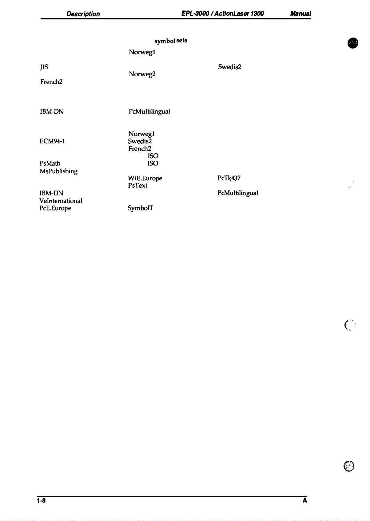
Font Symbol Sets
HP LaserJet 4L Mode (bitmap fonts): 26 symbol sets
DescriMion
EPL4009
IActionLsser 13tM
Service Msnud
Roman-8
French
JIS ASCII
ANSI ASCII
French2
Legal
IRV
IBM@ Portuguese
IBM-DN
HP LaserJet 4L Mode (scalable fonts): 34 symbol sets
Roman-8
ECM94-1
UK
Legal
PsMath
MsPublishing
Math-8
Windows
IBM-DN
VeIntemational
PcE.Europe
Wingdings
Norwegl
HP German
ECM941
Norweg2
German
Chinese
Swedish
IBM Spanish
PcMultilingual
Norwegl
Swedis2
French2
8859-2
8859-9
VeMath
WiE.Europe
PsText
McText T
VeUS
SyrnbolT
1S0
1S0
Roman Extension
Italian
Swedis2
UK
HP Spanish
Spanish
Portuguese
IBM- US
Italian
ANSI ASCII
German
Spanish
WiTurkish
DeskTop
PcTk437
IBM-US
PcMultilingual
PiFont
WiAnsi
,
:
.
.
,.
c?
c’
Rev.
I*
A
Page 19

EPL-3000/ActjonLaser 1300
Sendce
Manual
1.3 INTERFACE SPECIFICATIONS
The EPL-3000 is equipped with the following external interfaces:
■ Parallel interface
■ Optional Type-B interface
The ActionLaser 1300 is equipped with the following external interface:
I
Parallel interface
1.3.1 Parallel Interface
The parallel interface has two modes as follows:
■ Compatibility mode (same as parallel interface of Epson’s current page printer)
■ Reverse mode
1.3.1.1 Compatibility Mode of Parallel Interface
General
Descrjptjon
System:
Handshaking:
Connector type:
Applicable plug:
Transfer speed:
Signal timing:
Signal description:
DATA 1-8
STROBE
ACKNLG
STROBE synchronization, 8-bit parallel data transfer
BUSY and ACKNLG signals
P90-25027-1
57-30360 (Amphenol or equivalent)
Approximately 125,(XN bytes/second (maximum)
See Figure 1-3.
See Table 1-7.
o.5ps
(minimum) (minimum)
0.5ps
(maximum)
BUSY
(Amphenol) receptacle
o.5ps
V
LID
)
:4
\
1
0s
*
/
~
VALID
Rev.
1
or
IOps
(typical)
Figure 1-3. Compatibility Mode Signal Timing
A
1-9
Page 20

General Description
Table
EPL40~lActlonLaser 131M
1-7. Parallel Interface Pin Assignment
Service
Manual
Pin ~.
1
2-9 DATA 1-8
10
11
12
13
14
15
16
17
18
19”30
31
32
33
34
35
36
I
Signal Name
STROBE
ACKNLG
BUSY
PE
SLCT
AUTO-FEED
NC
GND
CHASSIS
NC
GND
m
ERROR
GND
NC
+5
SLCT
IN
GND
Uo
STROBE is
computer. The pulse width must be more than 0.5
IN
Normally it is HIGH, and data is latched at the trailing edge of
this signal.
DATA 1 to 8 are parallel data bits. When the signal is HIGH,
the data bit is 1, and when it is LOW, the data bit is O.
The most significant bit
IN
must be maintained for 0.5 @cc. on either side of the
STROBE signal active edge.
ACKNLG
of 1 or 10P. This signal goes
OUT
OUT
OUT
OUT
OUT . in paper jam state
reception is completed, which indicates that the printer can
accept new data. Timing with the BUSY signal is
through
The BUSY signal informs the host computer of the printer
state. When the signal is HIGH, the printer cannot accept
The PE signal indicates paper empty for the standard tray
selected through
paper cassette. Paper empty is indicated by HIGH.
Use in reverse mode.
Not used.
IN
.
Not used.
Logic ground level.
Connected to the printer chassis. The printer chassis
-
and the signal
.
Not connected.
.
Ground level for the
IN
The STROBE signal is ignored when this signal is LOW.
This level goes LOW when the printer is:
. out of paper
. in
enor
●
off
line
.
Same as for pins19 to 30.
.
Not used.
Pulled up to
.
Use the reverse mode.
a strobe pulse used to read data from the host
is an acknowledge pulse with an approximate width
SelecType.
SelecTyps
GND
are connected to each other.
twisted pair return signal.
state
+5V
through 1.0 KQ resistance.
Description
(MSB)
is
DATA8.
LOW when the data
or command,
p.sec.
The signal state
speci%d
data,
or for the optional
GND
1
1-1o
Rev.
,...
L
A
Page 21

EPL-3000/ActionLaser
1300 Service Manual
General Description
1.3.1.2
The reverse mode for the EPL-3000/ActionLaser 1300 supports
reverse mode. This section describes the nibble mode. This
which the printer can inform the computer of its status by EJL
System:
Connector type:
Applicable plug:
Signal description:
Reverse Mode
IEEE-P1284
P90-25027-1
57-30360 (Amphenol or equivalent)
See Table 1-8.
nibble mode
(Amphenol) receptacle
Table 1-8. Parallel Interface Pin Assignment
Pin No.
1
Signal Name
STROBE
2-9 DATA 1-8
10
11
ACKNLG
BUSY
12 PE
13
14
15
16
17
18
19-30
31
32
33
34
SLCT
AUTO-FEED
NC
GND
CHASSIS
NC
GND
INIT
ERROR
GND
NC
35 +5
36
SLCT
IN
GND
I/o
HostClk:
IN
request values from the host computer during negotiation.
This signal is a strobe pulse used to read extension
The signals are data bits of extension request values during
negotiation. This printer supports the following values:
IN
0000 0100: Request Device ID (by nibble mode transmission)
0000 0000: Request nibble mode
OUT
OUT
PtrClk:
Printer data sending clock.
PtrBusy:
Printer sending data bits 3 and 7 during data transfer
to host computer.
OUT AckDataReq: Printer sending data bits 2 and 6 during data
transfer to host computer.
OUT
Xflag:
Printer sending data bits 2 and 6 during data transfer to
host computer.
HostBusy: This signal informs the printer of the host computer
IN
state. When the signal is HIGH, the host computer cannot
accept data.
Not
USed.
Logic ground level.
Connected to the printer chassis. The printer chassis
-
and the signal
GND
Not connected.
Ground level for the twisted pair return signal.
nlnit:
IN
OUT
High level fixed
nDataAvail:
Printer sending data bits O and 4 during data
transfer to host computer.
Same as for pins19 to 30.
Not
USed.
Pulled up to
1264Active:
IN
P1264
+5V
through 1.0 KQ resistance.
If this signal is set to HIGH, this printer active
(reverse mode).
Description
are connected to each other.
IEEE-P1284
printer can run in reverse mode, in
~nd
PJL commands.
nibble mode and WPS
GND
Rev.
A
1-11
Page 22

General Description
Figure 1-4 shows the parallel interface state switch diagram.
EPL401X1/ActionLaser
131#
Service Manual
[
Forvvard
Data
Transfer
o
I
Compatibility Mode —-----l
. STROBE
ACK and
ERR=HIGH
No data sent
BU:Y
SLCT
IN=HIGH
r
Failed
Negotiation
J
ERR= LOW
Sending data
ERR= LOW
SLCT
N= LOW
AUTO
FEED= LOW
AUTO
FEED=HIGI
A
Reverse
Idle
(
Figure 1-4. Parallel Interface State Switch Diagram
)
ERR= LOW
‘\ Host
I
Q
1-12
Rev.
A
Page 23
EPL-3000 /ActionLaser 1300 Service Manual
Figure 1-5 shows the negotiation timing chart.
General Description
DATA
SEL4N
STROBE
AUTO-FEED
ACKNLG
BUSY
PE
Peripheral Busy Status
~
Current Peripheral
Stafus
OOh or 04 h
/
SLCT
ERROR
Current Peripheral
Compatibility
Stalus
k,-
/
Negotiation
~
Figure 1-5. Negotiation Timing Chart
Note 1: The signal is set to HIGH when not sending data.
The signal is set to LOW when sending data.
Note 2: The signal is set to HIGH if the extension request value is
Note 3: HB DA: Host Busy Data Available
HB DNA: Host Busy Data Not Available
x
! Notel ;
\
;
Note 2
\
I Notel !
\
L-A
:
HB DA or : Idle or
HB DNA
(Note 3)
04h.
;
H
Transfer
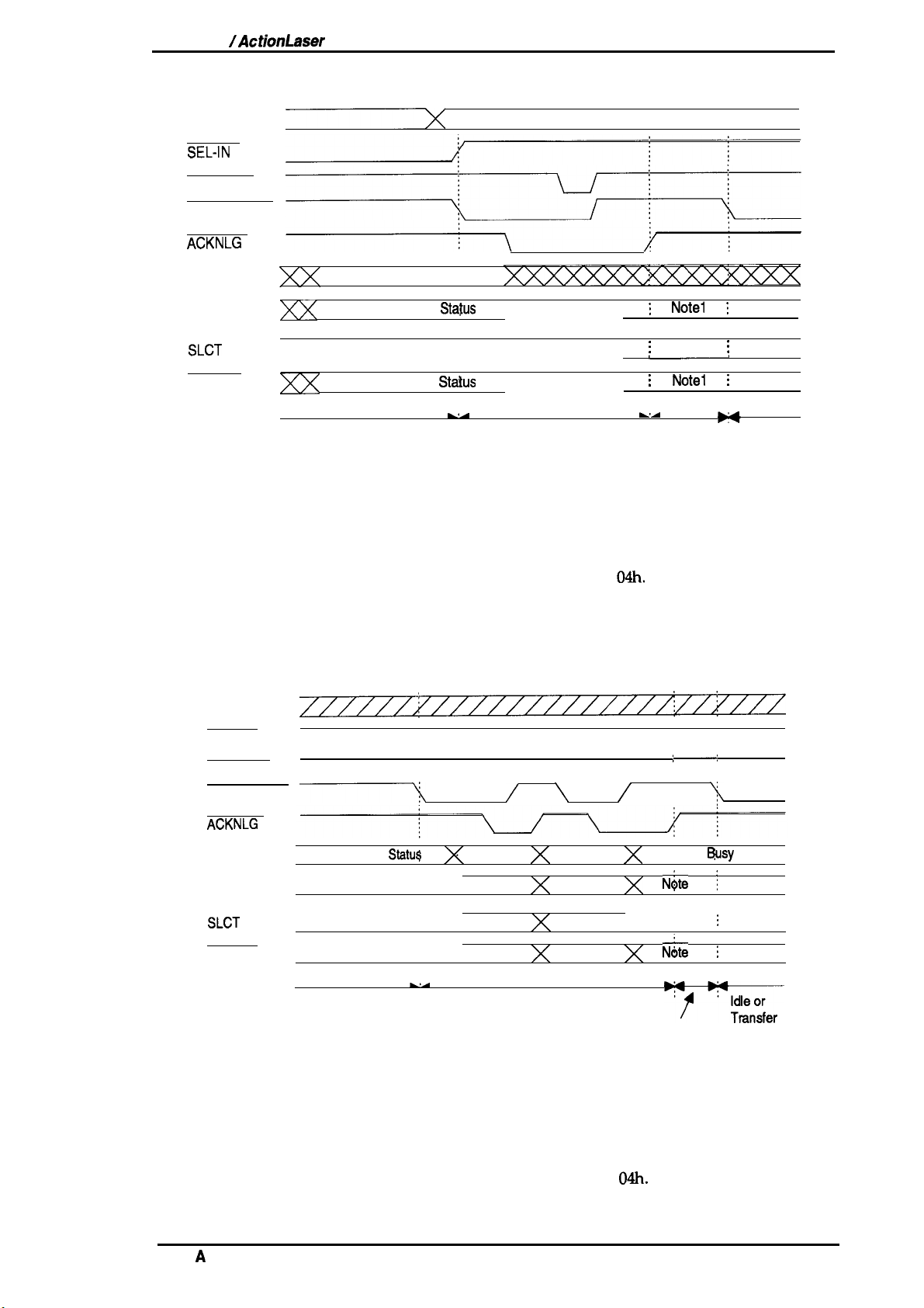
Figure 1-6 shows the data transfer timing chart.
DATA
SEL-IN
STROBE
AUTO-FEED
ACKNLG
BUSY
Peripheral Busy
Statu$
PE
SLCT
ERROR
-
HB DA
Figure 1-6. Data Transfer Timing Chart
/
Bit 3 Bit
\ /
7
Bit 2 Bit 6
Bit 1
Bit O
Negotiation
Bit 5
Bit 4
X
Peripheral
N4te
N&e 2
N;te
HB DAor
HB DNA
(Note
;—:
3)
1
1
‘$
8usy
j
;
;
Status
Note 1: The signal is set to HIGH when not sending data.
The signal is set to LOW when sending data.
Note2: The signal is set to HIGH if the extension request value is
Note3: HB DA: Host Busy Data Available
HB DNA: Host Busy Data Not Available
Rev.
A
04h.
1-13
Page 24

General Description
Figure 1-7 shows the termination timing chart.
DATA
SEL-IN
STROBE
AUTO-FEED
ACKNLG
EPLiXNM/ActionLasar
131M Servke Mimual
BUSY
PE
SLCT
ERROR
Peripheral
HB DNA, Idle, ‘
Busy
Statu$
Note
Note 2
Note 1
1 ;
\
;
H
Termination
or HB DA
Figure 1-7. Termination Timing Chart
Note 1: The signal is HIGH when HB DNA.
HB
The signal is LOW when
Note 2: The signal is set to HIGH if the extension request value is
Note3: Idle= LOW
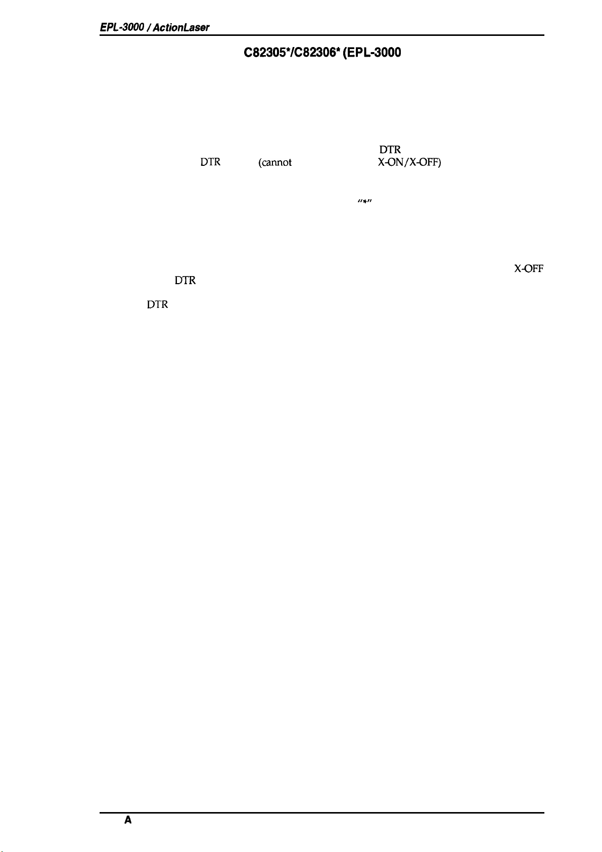
Figure 1-8 shows the interrupt timing chart.
DATA
DA.
\ Peripheral Busy Status
:
Current Peripheral Status
:
Current Peripheral Status
Compatibility
04h.
3EL-IN
STROBE
AUTO-FEED
ACKNLG
BUSY
~
PE
SLCT
ERROR
Note 1
Reverse Idle
Figure
Note 1: The signal is set to HIGH if
Peripheral Busy Status
- : -
Interrupt
;
-,
1-8. Interrupt Timing Chart
theextmsion
request value is
04h.
HB DA
.,
/
C
:
,*
..’;
?
.,
‘
c1
1-14
Rev.
A
Page 25
EPL-3000 /ActionLaser
1300 Service Manual
General Description
1.3.2 Optional Interface
Type:
Synchronization:
Protocol:
Transfer
Error handling: Overrun error:
speed:
RS-232C or current loop
Asynchronous start-stop system
Start bit:
Stop bit:
Data length: 7 or 8 bits
Parity:
X-ON/X-OFF (cannot be combined with
DTR
300,600,1200,1800,2400, 4800,9600, or 19200 bps
Parity error:
Framing error:
Breaking character: Ignored
C82305*/C82306* (EPL-3000
1
bit
1 bit
Odd,
even, or
control (camot be combined
Processed as missing data and replaced by “*”
Replaced by
Replaced by “*”
none
DTR
with
X~N/X-OFF)
““”
only)
control)
Handshaking
When the vacant area for data in the input buffer drops to 256 bytes, the printer outputs an
code or sets the DTR signal level to LOW, indicating that the printer cannot receive more data.
Once the vacant area for data in the buffer recovers to 512 bytes, the printer outputs an X-ON code
or sets the
DTR signal level to HIGH, indicating that the printer is again ready to receive data.
X~FF
Rev.
A
1-15
Page 26
General Description
EPL40~lActbnLaser 131M Sewke
Manual
1.4 OPERATING INSTRUCTIONS
This section describes the functions performed through the control panel, such as test print,
hexadecimal dump, and panel setting functions.
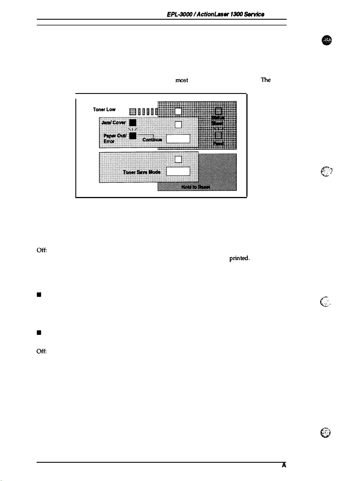
Control Panel
1.4.1
printer control panel gives you easy control over
The
consists
of indicator lights and buttons.
I
Figure 1-9. Control Panel
Indicator lights
■ Data
rrmst
common printer operations. The panel
off
Slow flashing:
Quick flashing:
on:
Orange color:
H
Jam/Cover
on:
Slow flashing:
Quick flashing:
H
Toner Save Mode
on:
Ot%
Flashing
Power off
Received data is stored in the printer but has not been
The printer is receiving or processing data.
There is no printable data remaining in the printer.
Toner low
Paper jam or cover open
Paper out or feed jam
Warning (Refer to “Message Display” section)
Toner Save Mode selected
Toner Save Mode not selected
The panel is being reset
pMted.
,,:
’.,
. .
.
,.
c
1-16
Rev.
A
Page 27

EPL-3000 /ActionLaser
Buttons
■ Status Sheet
Warning Measures
Feed
Continue
Status Sheet Printing
H
Toner Save Mode
1300 Service Manual
When the Jam/Cover light is quickly flashing, press this button to
clear a warning.
When the Data light is slowly flashing, press this button to print out
data in the printer’s memory.
When the Jam/Cover light is slowly flashing, press this button to
starts printing.
When the Data light is on, press and hold this button until the Data
light begins quickly flashing. A status sheet will them print.
General Description
Toner Save Mode
Reset
■ Toner Counter Reset (Toner Save Mode+ Status Sheet)
Toner Counter Reset
Press this button to turn the Toner Save Mode light on (Toner Save
Mode selected) or off (Toner Save Mode not selected), or to reset
Toner Save Mode.
Press and hold down this button until the Toner Save Mode light
begins flashing.
To reset the toner counter, press and hold down the Toner Save
Mode and Status Sheet buttons until the Data light turns green and
then flashes orange.
1.4.2 Service Mode
This printer has three service mcdes as follows:
■ Hexadecimal Dump
■ Factory Reset
EEPROM Format (EEPROM reset)
■
1.4.2.1 Hexadecimal Dump Mode
The hexadecimal dump mode is a useful
m~e,
hexadecimal dump
until Data light comes on.
turn on the printer while holding down the Toner Save Mode button
tool for troubleshooting data control problems. To enter
1.4.2.2 Factory Reset Mode
This mode resets all settings except the printer name and total printing counter. To enter factory
reset mode, turn on the printer while holding down the Toner Save Mode button until only the
Toner Save Mode light is on.
1.4.2.3 EEPROM Format Mode
EEPROM format operations are required only when the main controller board or EEPROM is
replaced. These operations are specified in the documentation accompanying these components.
EEPROM format functions (printer name, default paper size
printing counter, and other settings) are all stored in memory.
Defaults for the
Turn on the printer while holding down the Status Sheet and Toner Save Mode buttons until only
the Data light is flashing.
Note:
EEPROM format functions can be written to EEPROM as follows:
The printer name
selected by jumper J3 for the main controller board when this operation is performed.
(EPL-3000
or ActionLaser 1300) and default paper size
(A4
or letter), toner counter, total
(A4
or letter) are
Rev.
A
1-17
Page 28

General Description
EPL40(M/ActionLaser
13tX7
Service
Manuai
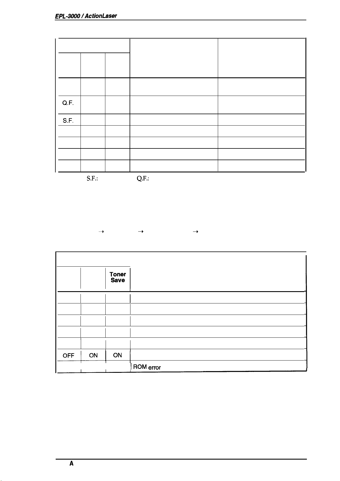
1.4.3 Message Display
This printer displays two types of messages on the indicator lights: status and error, and service
call error.
1.4.3.1
Status and Error Messages
If any of the following status and errors conditions occur, they will be displayed on the indicator
lights. The error must be cleared immediately using the measures shown in the following table.
Table 1-9. Status and
Indicator Light Display
T&on~r
Mode
F.
—
—
Data
—
—
—
Jam/
Cover
—
ON
Q.F.
Enor
Messages
Status
Resetting
Paper jam or cover open
Warning
An error follows.
Insufficient Memory
There is not enough memory to
print or download data.
Print Overrun
Engine speed faster than print
image processing.
If the printer has unused
memory, it automatically
recovers.
Measures
—
If paper jams, open the cover
and remove the jammed paper.
Then close the cover.
Press the Status Sheet
If
you
need an error statement,
print a status sheet. The status
sheet is the printed error
statement.
Erase
downloaded data or add
optional memory.
If the printer cannot
automsticslty
the PAGE PROTECT setting by
with the PJL
software).
recover, change
mmmand
button.
(utility
1-18
—
S.F.
—
Image Optimum
The printer
quality.
Paper Size Mismatch
The printing paper size is
different from the paper size
chosen.
EEPROM
The
EEPROM
the new settings.
Soft Error/CPU Error
Controller error
Paper empty or feed jam
uses a lower print
Error
cannot memorize
Erase downloaded data or add
optional memory.
Change the paper and print
again.
Try again
Sentice
Insed
then press the Status Sheet
button.
call
or clear the paper
ad
Rev.
A
Page 29
EPL-i?OOO/ActionLaser
1300 Service Manual
Table 1-9. Status and Error Messages (Continued)
Indicator Light Display
General Description
Data
OR
Q.F.
S.F.
ON
— —
—
OFF
F.: Flashing,
1.4.3.2 Service Call Error
This printer automatically checks the operating conditions of each component. If any abnormality
is detected, the printer displays an error message on the control panel.
While the printer detects a service call error, it continuously repeats the following display:
Jam/
Cover
—
OFF
—
—
—
OFF OFF
S.F.:
Toner
Save
Mode
—
—
—
—
ON
OFF
Slow Flashing,
Toner low
Data received or data
processing
Data held
Data not held
Toner Save Mode
No Toner Save Mode
No
power
Q.F.:
Status Measures
Prepare the new imaging
cartridge
—
—
—
—
—
—
Quick Flashing, OR.: Orange light
~
All lights on
Indicator Light Display
Data
ON
OFF
OFF
ON
ON
Cover
I
I
1
=-Q-oN 1
OFF I OFF I OFF
All lights off ~ Error code display ~ All lights off
Jam/
OFF
ON
OFF
ON
OFF
T&~~r
Mode
I
OFF
OFF
ON
r
OFF
I I
ON
[
‘N
Table 1-10. Service Call Error
I
I
I
Fusing unit error
Laser light error
Scanner motor error
1
Fan motor error
EEPROM format error
1
RAM error
1
I ROM
error
Error
Rev.
A
1-19
Page 30

General Description
1.4.4
Printer Sharing
l%is section describes printer sharing- It is possible to allocate each mode to parallel and optional
interfaces. The entire
receives the data first will print first.
User 1
memory
Mode Assignment
Parallel
*
Mode Assignment
will
be allocated to
HP mode
AWPS mode
EpsonScript
mode
L—
EPL+30W/ActionLaaer 19(M Servke Menuel
tie channels
that are used. The interface that
t-
Input buffer
Memory
User 2
Input
Bt#ter
The input buffer size is automatically adjustable from a minimum of 1/1000 of all memory to a
maximum of 1/5 of
all
1/1000 of
When the user
buffer size for the interface not processing data is a maximum
Note: While EPSONScript Level 2 is used, this printer sets the input buffer.
memory per one step.
AUX
Figure 1-10. Auto
all
memory. If the input buffer is
comects
the host computers
parallel
J
!
Sense Mode
full,
this printer expands the input buffer by
interface and optional interface, the input
~f
1/100 of all memory.
I
I
1.4.5 Emulation Mode Switch Function
This section describes the emulation mode switch function.
1.4.5.1 Emulation Switch by
The two types of emulation switch functions described below are available on this printer.
Together they are referred to as
SPL
SPL
(Shared Printer Language).
. .
c’
,,
EJL:
EPSON Job
This is EPSON’s original language system. It is able to
in Figure 1-11.
PJL:
Printer Job
This is HP’s original language, which is available with the LaserJet III Si printer.
It is able to skip among various destinations, as shown in Figure 1-11. The precise specifications for
this language are based on the HP LaserJet III Si.
The figure below shows three types of mode switching.
EJL
Neither
or
PJL.
nor
Then they enter another mode.
Unguage
Langua@
PJL
switches the mode directly. They first exit
1
PCL5e
4+
EJL
Figure 1-11. Emulation Switch by
sldp
among various destinations, as shown
tlw
current mode and return to
Am
I
SPL
EJL
,.
c“
1-20
Rev.
A
Page 31

EPL-3000 /ActionLaser 1300 Service Manual
1.4.5.2 Intelligent Emulation Switch
General Description
The Intelligent Emulation Switch
depending on the data sent from the host computer through one of the interface channels. It is able
to switch between EPSONScript and other modes as shown in the figure below.
PCL5e
(IES)
automatically switches the emulation switch mode,
EPSONScript
Figure 1-12. Intelligent Emulation Switch
1.4.6
Resolution Improvement Technology
The EPL-3000/ActionLaser 1300 printers have RITech (Resolution Improvement Technology),
which is designed to improve print quality at 300 dpi. With this method, the dot-map data
extracted from the image data is reassembled to improve the print data.
The main improvement from this technique is in eliminating
effective when the dot-map data fits the development characteristics of the printer mechanism. It is
PJL
therefore necessary to set appropriate values in
commands.
“jaggies”
4
123
in diagonal lines. It is most
1 inch
●
300
n
1 inch
/
R
300-
Figure 1-13. Effect of
Note:
The following settings are available in
OFF. When the toner density of area A is almost the same as that of area B (as shown in the figure
below), the
difficult to distinguish the shape of area A from that of area
RITech is not effective for printing a screen pattern or gray scale. In such cases,
must be set to OFF. (The default setting is MEDIUM.) Since the RITech effect depends on
the toner condition, it should be adjusted
the imaging cartridge is used for a long time.
PJL
commands for
RITech setting is optimum. In other words, the optimum setting is achieved when it is
when the imaging cartridge is replaced or after
RITech
RITech:
B.
RITech
DARK, MEDIUM, LIGHT, and
Rev.
A
1-21
Page 32

General Description
EPL40tM/ActionLaser
A
1
13(W
Service
#Amual
Figure 1-14.
1.4.7 Toner Save Mode
The Toner Save Mode uses about
substituting a gray shade for the
printed in full black.
black
Figure
1.4.8 Optional Memory
RITech
50Y0
less toner than normal. The printer saves toner by
inside of characters. The outlines of the characters are still
1-15.
Toner Save Mode
Adjustment
Upper Edge
If you have difficulty printing complex, graphics-intensive pages or if you regularly use
downloaded fonts, you may need to install the
board. The printer’s controller board comes with 1.0 MB of RAM installed.
By installing additional SWIMS, you can increase the printer’s memory to a total of 5 MB, including
the resident memory.
Epson supplies several types of SIMM memory options. Other
vendors. Be sure that the SIMM meets the requirements listed below.
■ 72-pin type
● Capacity is
■ Access speed is less than 70
■ Size is within the following dimensions:
mm(l.42 in.)x 1(XI
36
oneofthefollowing: 1,2,4MB
m.
mm (4.25
in.)x
IOmm (.39in.) (Hx W x D)
optioml SIMM sets on this printer’s controller
SIMMS
can be purchased from other
1-22
Rev.
A
Page 33

EPL-3000
/ActionLaser
1300 Service Manual
1.5 MAIN COMPONENTS
General Description
To simplify maintenance and repair, the main components of the
been designed for easy removal and replacement. The main
Q C144
Cl
Q PWB-E
Cl PWB-F
Cl
U
Cl
Cl
Cl
MAIN Board
ROM SIMM board
Board
Board
Optical Unit
Fusing Unit
Drive Unit
Imaging Cartridge
Housing
Video controller circuit and engine controller circuit board
Optional ROM module
Power supply circuit board
High-voltage supply circuit board
PWB-F
EPL-3000 /ActionLaser
components are:
Fusing
(hit
.
1300 have
Figure 1-16”. Component Layout
PWB-E
Rev.
A
1-23
Page 34

General Description
EPL-30~/ActionLaaar 131M hvke
Manual
1.5.1
The
functions of the video controller circuit are receiving print data from the host, generating the print
image (video), and sending the print image to the engine controller
Motorola
and custom
■
Note:
C144
MAIN Board
C144
MAIN board is a video controller circuit and
68ECCX10,
Memory chips
Code ROM: two
Font ROM: one
Code and font ROM: one
4Mbit
DRAM (IC1O, 11)
16Kbit EEPROM (IC8)
This printer can select one included code and font
16-bit, 16.7 MHz CPU (location:
ICS
are assigned to the 16 MB memory space.
4Mbit EEPROM (IC17,
8Mbit
mask ROM
16Mbit
18) or one
(M80ATBD: IC8)
mask ROM
(IC8)
engine
IC6)
8Mbit
controller
is used, and the following memory chips
mask ROM
ROMora
arcuit
board. The primary
arcuit via the video interface. A
. .
(IC19)
separate type.
Table 1-11. ROM and Jumper Settings
Jumper Settings
J2
1-2
J4
1-2
I
IC17
4Mbit
EEPROM EEPROM
Code U Code L
4Mbit
ROM Locations
IC18
IC19
—
IC8
8Mbit
Mask
Font ROM
c’
—
.
scanning (the polygon mirror drive motor), image
(lC5)
(IC13)
1-2
2-3
C144
MAIN boards used as after-service parts. The following table shows
1-2
1-2
■
Custom
ASIC
ASIC E05B01 (IC9)
ASIC
PAL
The engine controller arcuit consists of an M37451M4 8-bit CPU (including a MASK ROM) and a
gate array. The circuit controls laser
synchronization, laser beam pulse width, and power.
There are two types of
differences between them.
ICS
E05A83
E05B04
E06A01 (IC22)
Table 1-12. Differences in Components for the
EPL4~
Optional
(CN5)
IC2,
Jumper
3
intefface
J3
connector
Connector used
IC
socket used
short
.
—
8Mbit
Mask
Code ROM
—
C144
MAIN Boards
ActionLaser 1300
None
None
8Mbit
Mask
Font ROM
16Mbit
Mask
Code & Font
ROM
-.
(..
Note:
The first release
1-24
C144
MAIN board also has a small board
(C144
SUB board).
Rev.
A
Page 35

EPL-3000 /ActionLaser 1300 Service Manual
7
General Description
E05B04
(IC23)
E05A83 (IC5)
\
CPU
,E05B01
, ROM
\
‘ROM
(IC6)
(IC9)
(IC8)
ROM (IC17)
(IC18)
Figure 1-17. C144 MAIN Board
1.5.2
This printer can use an optional ROM SIMM board. It is a code ROM for other software modes.
1.5.3
The
the AC line voltage into +12 V and +5 VDC voltages. There are two types of power supply board,
the 120V and 220/240V type. The difference between the two circuits is only in the input section.
ROM
SIMM Board
PWB-E
PWB-E
Board
is the power supply board, which consists of a switching regulator circuit. It converts
Do not touch VRIE on
PWB-E
board, as it is set at the
Figure 1-18.
PWB-E
factoy
Board
and should not be changed.
Rev.
A
1-25
Page 36

General Description
EPL40@ /ActionLaser
1300 Service
Manual
1.5.4
The
charge bias, and image transfer bias.
PWB-F
PWB-F
Do
not touch
Board
is the high-voltage supply circuit board. It converts the development bias,
VR2F
on
PWB-F
board, as it is set
D
Figure 1-19.
@
VR2F
PWB-F
at the
fhctory
Board
and
should not be
OPC
drum
changed.
1.
1.5.5 Optical Unit
The optical unit consists of the laser diode
which drives the polygon mirror
generated by the laser diode is conducted to the
as well as several mirrors and lenses, to create a latent
tbr
laser
(sernkonductor
scannin~
and several mirrors and lenses.
OPC
drum
elecbvphotographic
Figure 1-20. Optical Unit
laser), the mirror motor (
surfaa?
by way of the polygon mirror,
image on the drum.
scanner motor)
The
laser beam
1-26
Rev.
A
Page 37

EPL-3000 /ActionLaser 1300 Service Manual
General Description
1.5.6 Fusing Unit
The fusing unit fixes the toner to the paper using heat and pressure. This unit has a heater lamp,
thermistor, and thermal fuse. There are two types of
type. The only difference between them is the heater lamp:
fusing uNts,
the 120 V type and the 220/240 V
. .
1.5.7 Drive Unit
The drive unit consists of the main motor and a series of gears and clutches. It drives the paper
transport rollers, OPC drum, sleeve roller, fusing roller, and some other mechanisms.
Figure 1-22. Drive Unit
1.5.8 Imaging Cartridge
The core mechanisms of the printing process, such as charging, developing, and cleaning, are
integrated into this imaging cartridge.
Rev.
Figure 1-23. Imaging Cartridge
A
1-27
Page 38

Chapter 2 Operating Principles
Table of Contents
2.1 ENGINE OPERATION
2.1.1
Print Process. . . . . . . . . . . . . . . . . . . . . . . . . . . . . . . . . . . . . . . . . . . .
2.1.1.1
Paper Feeding . . . . . . . . . . . . . . . . . . . . . . . . . . . . . . . . . . . . . . . 2-3
2.1.1.2 Imaging Cartridge. . . . . . . . . . . . . . . . . . . . . . . . . . . . . . . . . . .
2.1.1.3
Drum Charge . . . . . . . . . . . . . . . . . . . . . . . . . . . . . . . . . . . . . . .
2.1.1.4 Laser Exposure.. . . . . . . . . . . . . . . . . . . . . . . . . . . . . . . . . . . .
2.1.1.5 Development. . . . . . . . . . . . . . . . . . . . . . . . . . . . . . . . . . . . . . . . 2-6
2.1.1.6 Drum Cleaning . . . . . . . . . . . . . . . . . . . . . . . . . . . . . . . . . . . . .
2.1.1.7 Image Transfer.. . . . . . . . . . . . . . . . . . . . . . . . . . . . . . . . . . . .
2.1.1.8 Fusing . . . . . . . . . . . . . . . . . . . . . . . . . . . . . . . . . . . . . . . . . . . .
2.1.1.9 Paper Exit . . . . . . . . . . . . . . . . . . . . . . . . . . . . . . . . . . . . . . . . .
2.I.2
Engine Control. . . . . . . . . . . . . . . . . . . . . . . . . . . . . . . . . . . . . . . . . . . . . 2-8
2.1.2.1 Main
2.1.2.2
2.1.2.3 FuserControl . . . . . . . . . . . . . . . . . . . . . . . . . . . . . . . . . . . . . . 2-12
2.1.2.4 Polygon MotorControl . . . . . . . . . . . . . . . . . . . . . . . . . . . . . . .
2.1.2.5 LaserDiode Drive. . . . . . . . . . . . . . . . . . . . . . . . . . . . . . . . . . . 2-15
2.1.2.6 BiasVoltages and LaserDriveTiming . . . . . . . . . . . . . . . . . . .
2.1.2.7 Fan Motor Control. . . . . . . . . . . . . . . . . . . . . . . . . . . . . . . . . .
2.1.2.8 Power Supply Circuit Functions and Safety protection . . . . . . . 2-19
PaperTake-Up and paper Exit Sensors . . . . . . . . . . . . . . . . . .
MotorFunctions and Control . . . . . . . . . . . . . . . . . . . . . . . 2-9
2-1
“
. 2-2
.
2-4
.
2-5
.
2-5
.
2-6
.
2-6
.
2-7
.
2-7
2-11
2-14
2-16
.
2-18
2.2
VIDEO CONTROLLER OPERATION
2.2.1
C144MAlN
Board Operation . . . . . . . . . . . . . . . . . . . . . . . . . . . . . . . . .
2.2.1.1 Reset Circuit . . . . . . . . . . . . . . . . . . . . . . . . . . . . . . . . . . . . . .
2.2.1.2
BusControlCircuti
. . . . . . . . . . . . . . . . . . . . . . . . . . . . . . . . . . 2-22
2.2.1.3 Interrupt Control . . . . . . . . . . . . . . . . . . . . . . . . . . . . . . . . . . .
2.2.1.4 DRAM Management. . . . . . . . . . . . . . . . . . . . . . . . . . . . . . . . . 2-23
2.2.1.5 Parallel Interface Circuit . . . . . . . . . . . . . . . . . . . . . . . . . . . . . . 2-24
2.2.1.6 Optional Type-B
lntefface.
2.2.1.7 Video Interface . . . . . . . . . . . . . . . . . . . . . . . . . . . . . . . . . . . .
2-20
2-20
.
2-22
.
2-23
. . . . . . . . . . . . . . . . . . . . . . . . . . . . 2-24
.
2-24
Page 39

List of Figures
Figure 2-1. Main Components. . . . . . . . . . . . . . . . . . . . . . . . . . . . ..........2-1
Figure2-2.
Figure 2-3. Paper Feeding . . . . . . . . . . . . . . . . . . . . . . . . . . . . . . . . . . . . . . . . 2-3
Figure 2-4. Imaging Cartridge . . . . . . . . . . . . . . . . . . . . . . . . . . . . . . . . . . . . . . 2-4
Figure 2-5. Drum Charge . . . . . . . . . . . . . . . . . . . . . . . . . . . . . . . . . . . . . . . . .2-5
Figure2-6.
Figure 2-7. Development. . . . . . . . . . . . . . . . . . . . . . . . . . . ...............2-6
Figure2-8.
Figure 2-9. Fusing. . . . . . . . . . . . . . . . . . . . . . . . . . . . . . . . . . . . . . . . . . .. ...2-7
Figure2-10.
Figure 2-11.
Figure 2-12. P/C
Figure2-13.
Figure2-14.
Figure2-15.
Figure2-16.
Figure 2-17. Sensor On/Off Timing. . . . . . . . . . . . . . . . . .“. . . . . . . . . . .....2-11
Figure 2-18. Fuser Control
Figure 2-19. Temperature
Figure 2-20. Polygon Motor
Figure 2-21. Polygon Motor Driving Start Timing . . . . . . . . . . . . . . . . . . . . . . .
Figure 2-22. Laser Diode Drive
Figure 2-23. Laser Emission Power Adjustment Timing . . . . . . . . . . . . .....2-16
Figure 2-24. High-Voltage
Figure 2-25. Print Process. . . . . . . . . . . . . . . . . . . . . . . . . . . . . . . . . . . .....2-17
Figure 2-26. Print Sequence (Staft). . . . . . . . . . . . . . . . . . . . . . . . . . . . . . . . .
Figure 2-27. Print Sequence (End) . . . . . . . . . . . . . . . . . . . . . . . . . . . . . . . . .
Figure 2-28. Printing Multiple Pages. . . . . . . . . . . . . . . . . . . . . . . . . . . .....2-18
Figure 2-29. Fan Motor Control Timing . . . . . . . . . . . . . . . . . . . . . . . . . . . .. .2-18
Figure2-30.
Figure 2-31.
Figure 2-32. Data
Figure 2-33. Reset Circuit. . . . . . . . . . . . . . . . . . . . . . . . . . . . . . . . . . . .....2-22
Figure 2-34. Bus Control
Figure 2-35. DRAM Management . . . . . . . . . . . . . . . . . . . . . . . . . . . . . . . . . . 2-23
Figure 2-36. Parallel
PrintProces sDiagram . . . . . . . . . . . . . . . . . . . . . . . . . . . . . . ....2-2
LaserExposure. . . . . . . . . . . . . . . . . . . . . . . . . . . . . . . . . .......2-5
Image Transfer . . . . . . . . . . . . . . . . . . . . . . . . . . . . . . . . . . . . . ...2-6
Engine ControflerConn*ing Diagram . . . . . . . . . . ...........2-8
”GearPositions
Drive
. . . . . . . . . . . . . . . . . . . . . . . . . . . . . . . . . . . . . . . . .. .2-9
Developing Drive . . . . . . . . . . . . . . . . . . . . . . . . . . . . . . . ......2-9
Feeding Drive... . . . . . . . . . . . . . . . . . . . . . . . . . . . . . . . ......2-9
Fusing Drive . . . . . . . . . . . . . . . . . . . . . . . . . . . . . . . . . . . .. ....2-8
Main
Power
MotorDriveCircu~
SupplyCircuti
C144
MAIN Board
Flow
Intedace Cimuti
. . . . . . . . . . . . . . . . . . . . . . . . . . . . . . . ........2-9
. . . . . . . . . . . . . . . . . . . . . . . . . . . . . . .
Circuk.
Control.
Control
Circuti
Supply Block
Block Diagram. . . . . . . . . . . . . . . . . . . . . .
Block
Diagram . . . . . . . . . . . . . . . . . . . . . . . . . . . . . . . . . . .
Circuti
. . . . . . . . . . . . . . . . . . . . . . . . . . . . . . .....2-22
. . . . . . . . . . . . . . . . . . . . . . . . . . . . .....2-12
. . . . . . . . . . . . . . . . . . . . . . . . . . . . . . . . .
Circuit . . . . . . . . . . . . . . . . . . . . . . . . . . .
. . . . . . . . . . . . . . . . . . . . . . . . . . . . . .
Diagram. . . . . . . . . . . . . . . . . . . . . .2-16
Diagram . . . . . . . . . . . . . . . . . . . .....2-20
. . . . . . . . . . . . . . . . . . . . . . . . . . . . . . . 2-24
2-10
2-12
2-14
2-14
2-15
2-17
2-17
2-19
Z-21
e
~~
c
c
i
Table 2-1. Gears and
Table 2-2. Laser Diode
Table 2-3. Functions of
Rollers
Control Circuti
C144 MAIN Board
List of Tables
. . . . . . . . . . . . . . . . . . . . . . . . . . . . . . . . .....2-10
. . . . . . . . . . . . . . . . . . . . . . . . . . . . . .
Eiements . . . . . . . . . . . . . . . . . . .
2-15
2-20
. .
,, .
.
c)
Page 40

EPL-3000
/Action Laser 1300 Service Manual
2.1 ENGINE OPERATION
Operating Principles
This section describes the functions and operating principles of the
EPL-3000/ActionLaser
engine.
Figure 2-1 shows the locations and names of the main engine components.
1
2
3
4 56 789
1300
10
11
12
13
14
20
1. Paper exit tray
2. Optical unit
3. Imaging cartridge
4. Exit roller
5. Thermistor
(THl)
6. Upper fusing roller
7. Thermal fuse
(TFl)
8. Heater lamp (Hi)
9. Fusing separator
10. Paper exit sensor
(PC2)
19
18
17
16 15
11. Lower fusing roller
12. cooling fan
13. Image transfer roller
14. Main motor (Ml)
15. Paper Take-up sensor
16. Transport roller
17. Paper take-up roller
18. Polygon motor
19. Paper Guide
20. Paper tray
Figure 2-1. Main Components
(PC1)
(M2)
Rev.
A
2-1
Page 41

Operating Principles
2.1.1 Print Process
This section describes the print process from paper feeding to paper exit.
Figure 2-2 shows a dia~am of the print process.
EPL4UtM/Action
Laser 131M Service Wmnd
6.
/’ 3
\
Imaging Cartridge
“
‘L
--- —. —-—--
laser
Exposure
1.
./-
Paper
Feeding
+=-n
-,
9.
--
.“
.
Figure 2-2. Print Process Diagram
.
-.
I
.
c
:,..
Q“
2-2
Rev.
A
Page 42

EPL-3000
/Action Laser 1300 Service Manual
Operating Principles
2.1.1.1
On the multi-purpose tray (standard tray), various sizes of paper can be fed by fitting the paper
guide against the sides of the paper.
The depressing cam is fixed to the shaft of the paper take-up roller, but the transport rollers are
free. The transport rolls are rotated by the rotation of the transport roller. The depressing cam
presses the paper lifting-up plate.
When the paper take-up solenoid
depressing cam releases to feed the first sheet of paper.
The timing to align the leading edge of paper with the image is determined by the paper take-up
sensor
Both of the sensors are comprised of a photo interrupter and an actuator. When the paper turns the
actuator on, output from the paper take-up sensor
exit sensor
Paper Feeding
(PC1).
(PC2)
switches to “H”.
(SL1)
is actuated, the paper take-up roller rotates and the
(PC1)
switches to “L” and output from the paper
Paper
Roller
Pape
Plate
Figure 2-3. Paper Feeding
Rev.
A
2-3
Page 43

Operating
Prhcipks
EPL-3tXN)lActh Lasar 1300
Service
Afmua/
2.1.1.2
The imaging cartridge consists
cleaning unit, the toner bottle, and the used toner bottle, all
Imaging
Cartridge
of the drum
chargin&
developing and cleaning sections; the
combimxi
10 9
in a single unit.
8
11
@’&,
1
Figure 2-4. Imaging Cartridge
This
1. Toner Hopper
2. Toner Agitating Screw
3.
Toner Transport Rollers
4. Doctor Blade
5. Sleeve
6. Flexible Sleeve
7. PC Drum
8.
Cleaning
9.
Drum Charge Brush
10. Used Toner Box
11. PC Drum Protecting Cover This
Roller
BIade
contains the toner.
This mixes
transport rollers.
These
transport toner to the
This
sprea&
toner passes between the doctor blade and the flexible sleeve, it
becomes negatively charged though friction.
These are used to rotate the flexible
This transports toner to the surface of the PC drum and
developing.
‘l’he latent image is formed by laser beams
drum, and development is carried out by the flexible sleeve. The
developed image is then conveyed to the
After the image is transferred, toner left on the surface of the PC
drum (used toner) is wiped away by this blade.
This negatively
Used toner is
protects the surface of the PC drum when it is removed from
the printer unit.
2
3
the toner in the toner hopper and feeds it to the
a thin,
charges the PC
collected here.
4
ewm
coat of toner over the flexible sleeve. As
5
skeve
drum.
roller.
6
skeve.
on
surt%ce
7
the surface of the PC
of the paper.
tier
ccmtrols
. ,.
c
.:
24
Rev.
A
Page 44

EPL-3000
/Action Laser 1300 Service Manual
Operating Principles
2.1.1.3
Drum charge is the process of charging the PC drum with static electricity before laser exposure.
This printer
brush charge, there is no generation of ozone as a result of corona discharge. This method also
allows the drum to be charged at a low voltage, because a direct electric load is applied to the PC
drum.
Drum Charge
uses
the brush charge method, rather than corona charge, to charge the drum. In
Imaging Cartridge
E:;d-’EJ
/-Rayon Brush
!
Q-
“
PC Drum
%
approx.
-1.2KV=
A: Drum Charge Bias
T
C: Doctor Blade Bias
B: Developing Bias
D: Drum Ground
Figure 2-5. Drum Charge
2.1.1.4 Laser Exposure
Laser exposure is the process
laser beams emitted from the optical unit. The mirror motor (scanner motor) rotates the four-sided
mirror counterclockwise to produce a laser light scan. (One side of the mirror produces one scan.)
The SOS (start of scan) sensor detects the laser rays from the SOS mirror and outputs the SOS
signals to make the starting position of each line of the image uniform.
Laser emission
PC Drum
Approx.
-50V
of creating an invisible static electric image on the PC drum with
Print Head Unit
Sos
LD
Rev.
Invisible
electricity image
A
static-
~
Polygon
Figure 2-6. Laser Exposure
Motor
2-5
Page 45

Operating
Principhs
EPi-3#0/Actfon tier IW
Sefvke
MOnual
2.1.1.5 Development
Development is the process of creating a toner image on the PC drum by applying toner to the
invisible static electric image.
sleeve. When the toner passes between the doctor blade and the flexible sleeve, it becomes
negatively charged. The flexible sleeve transports toner to the surface of the PC drum and controls
the development with the developing bias voltage.
No positive toner is transported, and the dwtor blade is charged to prevent the printing from
having a foggy background.
- Resin Sleeve
\
PC Drum
The
doctor blade spreads a thin, even
mat
of toner over the flexible
c
.>
‘1
Toner Image
Figure 2-7. Development
2.1.1.6
After the image is transferred onto paper, any re
the cleaning blade and collected in the used toner bottle.
2.1.1.7 Image
Image transfer
during development.
transfer, as the image transfer process. In roller image transfer, there is no generation of ozone as
there is with corona discharge. Also, there is no blurring caused by motion in the image
because the image transfer
A reverse bias voltage is applied so that the positive toner is not
roller. (The drum charge bias voltage is used.)
Drum Cleaning
maining
Transfer
is the process of transferring to the paper the toner image created on the PC
?his
printer uses the roller image transfer method, instead of
roller
pressure bonds the paper
Drum
toner on the PC drum is scraped off by
corona
vvith
the PC drum
transkwred
onto the image transfer
PC
Drum
drum
image
transkr,
rpc
Image Transfer Roller
2-6
Figure
F&. ’
J
2-8.
Image Transfer
+
d
@
Reverse Bias &
Approx. -0.5KV
Sequential
Approx. 3.5KV
AA
Bias
-!-
–
Rev.
A
Page 46

EPL-3000
/Action Laser 1300 Service Manual
Operating Principles
2.1.1.8 Fusing
Fusing is the process of fixing the transferred toner image onto the paper. This printer uses the
heating roller method for fusing. The heating roller method fixes the toner image with an upper
fusing roller that is heated by the heater lamp. The printer uses the cleaning roller to clean that
roller if it becomes dirty.
After the power is turned on, the heater lamp lights until the temperature of the upper fusing roller
reaches 168°C (334°F). After warm up, the mechanical control board controls the on/off operation
the
of the heater lamp, based on
Controller
Board
TH1 ;ignals
TH1
signals
Thermistor
from the thermistor.
[
1
/
>
d
b
I
/
5T
1
Photo
SCR
Thermal Fuse
~
Heater Lamp
/
Upper Fusing
Roller
+
Lower Fusing
Roller
Power Unit
Board
(PWB-E)
‘
%
7
— Paper Guide
Figure 2-9. Fusing
2.1.1.9 Paper Exit
The paper on which the toner image has been fused is fed to the face-down or face-up tray.
Rev.
A
2-7
Page 47

OpemtingPrincipbs
2.1.2 Engine Control
EPL-30tMlActkm Laser
134# Servkeh&mual
This section
The engine is controlled by the main controller board
controller connections.
Polygon
Scanner
motor
1-
PWB-D
describes engine control, the power supply board, and the
(C144
Hgh
Main
Controller
Board
Suppiy
Board
PWB-F
C144
LD drive
board
Paper
Exit
Sensor
PC2
>
MAIN
MAIN).
vottage
high voltage supply board.
I@um
2-10 shows the engine
)
Doctor Wade
)
image Transfer
)
Developing Bias
)
Drum Charge
)
GND2
Paper Take Up
-1
4
Sensor
Paper Take Up
Solenoid
Power SW
(CH2)
(CH1)
PCl
SL1
I
I
I
@
?.-
.“.
Power
supply
Board
PWB-E
Figure 2-10. Engine Controller Connecting Diagram
AC Power Input
Fan Motor
I
2-8
Rev.
6!$
A
Page 48

EPL-3000
/Action Laser 1300 Service Manual
2.1.2.1 Main Motor Functions and Control
Operating Principles
Power from the main motor (Ml) drive is used for the PC
(photoconductor)
drive, developing
drive, fusing drive, standard paper slot feeding drive, and lower paper cassette
drive. Figures 2-11 through 2-16 show the positions of the gears and rollers.
Figure 2-11. Gear Position
- Image
Transfer Roller
+leeve
(optioml)
Roller
feeding
—
4
3
-.
2<z.-.
Revolution
1497
r.p.m.
process Speed
23.51
(mmIs)
Figure 2-12. P/C Drive
Transport Roller
\
Paper Take-Up
Roller
11
10
—.
9
8—
—
.
3–
-
2—~--“
Figure 2-13. Developing Drive
Exit Roller
r
—
Upper Fusing Roller
Revolution
r
28.09
Process Speed
23.50 (mm/s)
r.p.m.
15
16
17
—.—.
.—
—
Figure 2-14. Feeding Drive
Rev.
A
3
-—.
i?
2
1.
9
Figure 2-15. Fusing Drive
2-9
Page 49

Operating Principles
No.
No.
of Gear
Teeth
EPi-31XM
Table 2-1. Gears and Rollers
Roller Neme
No.
/Action Laser 13(M Servke
No. of Gear
Teeth
Mhnual
Roller Name
1
2
3
4
5
6
7
8 57
9
10
Figure 2-16 shows the main motor drive circuit. The main motor (Ml) is a four-phase stepping
motor. This motor is controlled by the CPU
The power supply board
(Ml) with a constant current.
16
1 7/56 12
29/72
51
24/38
43
30
29/30
26/27
Main controller board
C144
MAIN Board
P/C Drum
(PWB-E)
has a stepping motor driver
Power Supply board
PWB-E
11
13
14 16
15
16
17
18
19
20
(IC201)
on the main controller
20
1 6/29
4Y48
24/59
3tY48
29
50
15
16 image transfer
Sleeve
Paper take-up
Transport roller
Upper fusing roller
Exit
IC.
This IC drives the main motor
rofler
roller
board
(C144 ~IN
roller
roller
).
CN201
Figure
10
CN3E
1
I
10 8
99
8
7 11
F
2-16. Main Motor Drive Circuit
. .
c
t,
. .
2-1o
Rev.
63
A
Page 50

EPL-3000
/Action Laser 1300 Service Manual
Operating Principles
2.1.2.2
The
Paper
~aDer take-up
i) ‘
To detect’ the top edge of the paper. The engine starts printing when the detection signal
TaktWp
and Paper Exit Sensors
sensor has three functions:
is received.
2)
To detect paper size. The printer detects the time it takes for paper to pass the take-up
sensor during paper feeding. A longer amount of time means that long paper is feeding;
a shorter amount of tome means that short paper is feeding.
To detect paper jams and feed jams.
3)
If one of the following conditions is detected, the printer assumes that a paper miss feed has
occurred. On detection of a jam, all elements except the fan motor (M3) are deactivated, with the
following exceptions:
If a paper is being transferred in the printer on detection of condition 1 below, the paper is
ejected and all elements are then deactivated.
●
if only the condition 1 below is detected, elements other than the heater lamp (Hi) are
deactivated since there is no paper in the fusing unit.
1.
The paper take-up sensor
(PC1)
is not turned on within the specified time after the paper
take-up roller starts to rotate.
2.
The paper take-up sensor
The paper exit sensor
3.
The paper take-up sensor
4.
(PC1)
is on when the power is on or the upper unit is closed.
(PC2)
is on when the power is on or the upper unit is closed.
(PC1)
is not turned off within 16.43 seconds after the leading edge of
the paper reaches the sensor.
The paper exit sensor
5.
of the paper reaches the paper take-up sensor
The paper exit sensor
6.
of the paper passes the paper take-up sensor
(PC2)
is not turned on within 5.89 to 7.89 seconds after the leading edge
(PC1).
(PC2)
is not turned off within
6.48 to 8.48
seconds after the trailing edge
(PC1).
Take Up Solenoid ON
Figure 2-17. Sensor On/Off Timing
[sec.]
Rev.
A
2-11
Page 51

Operating Principks
EPi+?OOO/Actbn
Laser
13tM
Service
hWual
2.1.2.3
The surface temperature of the
corresponding a&log voltage is appii~ to
Heater lamp
on/off signal output from
If HI is not turned off when
Fuser
Control
upper fusing
roller is detected by thermistor THl and the
IC20i
pin 62.
HI is turned on or off to provide fusing temperature control
IC201
pin%.
THl
detects an abnormally high fusing
by the heater lamp
temperature, H1 is
automatically turned off as follows.
When the surface temperature of the upper fusing roller detected by THl exceeds 200 W (392 “F),
the voltage applied
the outout from comparator goes
NAND~ircuit
to
1(202 pin 42 becomes higher than the reference voltage at
goes
frdm LOW-ti
Heater Lamp ON/OFF Signal
JQ=l
HIGH, thus turning off H1.
IC202
pin
41. Then
from HIGH to LOW. When this occurs, the output from the
Thermistor
r-
(TH1)
analog voltage
IJ!_kEl
TH1.Signal
C144 MAIN
Board
DC5V
R207
7’
R206
r+
Heater
Section
—
(
H <-- L L <-- H
II
)
IC203E
I
I
i
NAND
Circuit
50
,..
I
IC201
(CPU)
22
46
Figure 2-18.
Fuser
Control Circuit
The diagram below shows fluctuations in the temperature after the
on.
168
135
100
I
Temperature
0
(
c)
I
I
Figure 2-19.
Tempwature
I
I
I
I I
I
I
I
I
Control
power
I
1
t
I
t
1
1
I
I
supply has been turned
I
I
t
I
I
I
I
I
I
I
I
By
I
Mode
*
,.
“.. “j
c
2-12
Rev.
A
Page 52

EPL-3000
/Action Laser 1300 Service Manual
Operating Principles
1. Warming Up
2. During Standby
3. During Printing
4. Low Temperature
Standby Mode
If the following conditions occur, the printer detects a
The thermistor temperature is checked 12 seconds after warm-up starts and continues for the
1.
next 18 seconds.
If during that time the temperature of the thermistor falls to within 20‘C (68 “F) of the ambient
room temperature, a
2.
If the thermistor temperature does not reach 168 “C (334 “F) within 80 seconds after the warmup starts, a
3.
If the thermistor temperature falls below 70 “C ( 158 “F) during standby after the end of
detection in the non-pause mode of falls below 120 ‘C (248 0 F) during printing,
detected.
4.
If the thermistor temperature exceeds 200 “C (392 “F) during temperature control, a
is detected.
Note:
fuser
error is detected.
During pause mode, the control temperature is decreased to save power in the standby
state, heater lamp (Hi) being turned off.
When the power on/off switch is set to on and the printer is
initialized, warming-up starts and the heater lamp is lit. The heater
lamp remains lit until the temperature of the fusing section reaches
168 “C (337 “F).
The temperature of fusing section is controlled to keep it at about
135 “C (275 “F). If the standby state persists for 5 consecutive
minutes, the printer enters the low temperature standby mode.
When the controller gives the print instruction, the temperature is
controlled to keep the fusing section at about 168‘C (334 “F).
The temperature is controlled to keep the fusing section at about 100
‘C (212 “F).
fuser
error.
fuser
error is detected.
fuser
error is
fuser
error
The thermofuse
high level (over 200 “C (392 “F)).
(TFl)
cuts the power if the temperature of the fusing section rises to an abnormally
Rev.
A
2-13
Page 53

Opemthg
2.1.24
figure
r~ives
Principles
Polygon Motor Control
2-20 shows the polygon motor
the
POLGNM (M2.ON)
Main Board
(C144
signal.
MAIN)
POLLOCK
POLYGNM
PIH
POLCLK
Figure 2-20. Polygon Motor Control Circuit
The rotation of the polygon motor
SSCAN
motor
signal is not detected properly during this period, the printer assumes that the polygon
(M2)
is malfunctioning and stops the motor.
(M2)
EIZmlActbn
(M2)
control circuit.
CN205
SEL
GND 2
is detected within 5 seconds after starting the motor. If the
1
2
3
4
5
B
+12
The
Scanner Motor
M2
Laser IWO
polygon motor is driven while it
Sarvko
MmuaJ
., ., ,
..
. . .
c’
.
[sec.]
1111
I
I
M2:ON
SSCAN
I
~
Polygon Motor On
I
I
Illlllllimlllll
lllllllllllll
Figure 2-21. Polygon Motor Driving Start Timing
2-14
Rev.
A
Page 54

EPL-3000
/Action Laser
1300
Service Manual
Operating Principles
2.1.2.5 Laser
Laser diode emission is controlled by three signals
main board a 1 simal
(sensor) is located
Controller
Board
Diode
i~side-the
-LDATA
LD
VR1
Drive
(LDATA, LDVR1
(LDLVL)
from the laser diode drive board
laser diode. This sensor measures the laser power.
Laser Diode
PWB-D
3
LD
VR2
LD LVL
=!
-SSCAN
Laser Diode
Drive Board
SOS Sensor
and
(PWB-D).
7
LDVR2)
SOS Mirror
sent from the
The photo diode
Laser
Diode
Photo
Diode
Figure 2-22. Laser Diode Drive Circuit
Table 2-2. Laser Diode Control Circuit
I
Signal
LDATA
LDVR1
LDVR2
LDLVL value. The signal “H” shows that the current has reached the regulated value
SSCAN
This signal is the laser
and
when it is “H”, the laser is stopped emitting.
This signal adjusts the laser drive current so that the laser emission becomes
the regulated value (rough adjustment).
This signal adjusts the laser drive current so that the laser emission becomes
the regulated value (fine adjustment).
This signal indicates whether the laser drive current has reached the regulated
and the signal “L” shows that the current has not yet.
This signal is returned from the
the SOS sensor and is the main scanning direction synchronization signal. The
main board is timed with this signal and sends the
otioff
Description
signal. When it is “L”, the laser is allowed to emit;
PWB-D
to the main board. This is the signal to
LDATA
signal to the
PWB-D.
Rev.
A
2-15
Page 55

Operating
Principks
ERb30iW/Action
Lssw
MOO
Servke
A&mud
After the
0.74 seconds. At the same time, the laser emission power is adjusted.
main motor has been activated for 0.06
~
Main Motor On
LDATA
LDVR1
I
LDLVL
+
I
secmds,
0.74
the laser diode is
E
fbrcibly
[sec.]
Illu
activated
h
I
figure 2-23. Laser Emission Power Adjustment
After the main motor (Ml) has been driven fix 0.0S seconds, the laser diode is forcibly activatd for
0.74
seconds, during which time the laser diode emission is detected. If the
from the specified value during this period, the laser diode is assumed to be judged as
malfunctioning.
2.1.2.6
Figure 2-24 is a diagram of the drum charge, image transfer, and doctor blade bias voltages.
figure also shows the developing bias voltage control
from the
condition, the interlock switch is set to off, which
voltages.
Bias Voltages and Laser Drive Timing
arcuit.
+12 VDC
on the high voltage supply board
cuts the
(PWB-F).
These bias voltages are generated
If the printer detects a case open
+12
VDC
Timing
LDVR1
signal deviates
This
and in turn cuts the bias
,..
$
c’
i“.
These bias voltages are controlled by the main board
image transfer (roller) bias voltage control.
charged to
transfer roller is
signal is LOW, the PC drum is charged to
DB:CNT
voltage level (about -300
developing bias voltage level.
Power Suppry
Board
(PWB-E)
3.5K VDC
is an
+12 VDC
by the high voltage supply circuit. While this signal is HIGH, the image
chargwi
amlog
-Y%-
to -0.5K
signal for developing bias voltage control.
Inter Lock
VDC.
VDC)
using analog data. The image density is controlled by the
Main
Board
2144
MAIN)
. . . . . . . . . . . . . . . . . . . . . . . . .
The
CH1:ON
-1.2K VDC.
VDC
+12
DB:CNT
CH2:ON
CH1
:ON
While
this
sigmd
signal controls the dmm charge. While this
F
●
b
●
(C144
MAIN). The
is LOW, the image transfer
This
High Voltage Supply
Board
(PWB-F)
. . . . . .
CHXJN
signal controls the bias
Image
+
Bias
3.5K
. . . . . . . . . . . . . . . . . . . . . . .
. . . . . . . . . . . . . . . . . .
. . . . . . . . . . .
: ---
: ---
:. . . . . . . .
Developing
-9
Bias
about -300 VDC
Doctor Blade Bias
+
-600 VDC
Drum Charge
-D
-1.2 K
signal is the
roller
Transfer
(CH2)
Of -0.5 K
VDC
VDC
(CH1)
is
2-16
Figure 2-24. High Voltage Supply Block Diagram
Rev.
A
Page 56

EPL-3000
/Action Laser 1300 Service Manual
Operating Principles
Figure 2-25 shows the print process, and Figure 2-26 shows the start print sequence. The printer’s
engine starts printing when the PRINT signal is received from the video controller board.
t
Laser
Exposure
Laser
Brush Charging
Exposure
Development
Figure 2-25. Print Process
Print
\
PC Drum
Main Motor On
v
Transfer
[sec.]
Development
Image
Transfer
Paper Take-up
Solenoid
Figure 2-26. Print Sequence (Start)
Figure 2-27 shows the end of the print sequence.
rotating when the paper exit sensor turns off after
Print
v
Drum
Charge
Laser
Exposure
,,
,,
: :
4.72
A
Paper Take-up Sensor On
The printer stops the main motor (Ml) from
seconds.
[sec.]
Rev.
A
Image
Paper Take-up
Solenoid
: :
:
:
,,
A
Paper Take-up Sensor On
Figure 2-27. Print Sequence (End)
2-17
Page 57

Operating Principbs
EPf.-3iUM /Actbn Loser WXI
Figure 2-28 shows the multiple page printing sequence.
Servke
MmuaJ
Drum
Charge
Laser
Exposure
Development
,,
:,.
::
‘~
:
Image
Transfer
}
Paper Take-up
Solenoid
: :
,,
Figure 2-28. Printing Multiple Pages
2.1.2.7 Fan Motor Control
The
fan
motor (M3) rotates for the following periods and remains stopped for other than the
following periods:
Print
:
:
[sec.]
:
o.555;~
●
For 2 seconds after power-on.
●
Between 20 seconds after the start of printing and
●
For 20 seconds after all elements are stopped
20
seconds after the end of printing.
for detecting trouble, with the exception of a
except paper jam.
If the fan motor’s current detecting potential remains at 150 mV or less for 2
is assumed to be malfunctioning.
Note:
Current detecting potential means that the fan motor current is converted to the
corresponding voltage for detection purposes.
Power On
PRINT
Print end
~
M3: CNT
Figure 2-29. Fan Motor Control Timing
seconds, the fan motor
[sec.]
2-18
Rev.
A
Page 58

EPL-3000
/Action Laser 1300 Service Manual
2.1.2.8 Power Supply Circuit Functions and Safety Protection
Operating
Principles
The printer’s power supply board
as the bias voltage supply, main motor (Ml) drive, scanner mirror motor
(M3) drive, and solenoid drive. For safety protection, the +12
(PWB-E)
supplies +5
VDC
and +12
VDC.
The +12
(M2)
VDC
line is cut when the interlock
switch (case-open switch) is off.
Inter Lock
Sw
AC IN
---+
Power Supply Board
(PWB-E)
~~
~
~
~
+12
+5
SG
FG
Figure 2-30. Power Supply Circuit Block Diagram
VDC
is used
drive, fan motor
VDC
VDC
Rev.
A
2-19
Page 59

Operating Principks
EPi-30tWlAdon Laser 13tM &wvke
h&waJ
2.2 VIDEO CONTROLLER OPERATION
The video controller section generates the video signals for the received data. ‘l’he video controller
is a separate section of the
C144
MAIN board.
2.2.1
Figure 2-31 shows a block diagram of the video controller circuit
The
CPU, the standard cells developed
C144
MAIN Board Operation
C144
MAIN board contains the video controller, which consists of a 16-bit 68000 (16.67 MHz)
CPU
68000
(IC6)
ROM 16M
I
A
I
Option l/F
Parallel
Figure 2-31.
tbrthis
Option
ROM
E05B01
(IC9)
l/F
C144
printer,
EEPROM
(IC20)
E05A83
(IC5)
DRAM
D~s,
MAIN Board Block Diagram
section
ROM, anda
E05B04
(IC13)
of the
la
C144
MAIN bed.
16Kbit EEPROM.
ADDRESS
DATA
CONTROL
~
Video
-
Table 2-3 lists
Element
66000
CPU
ASIC E05A63
ASIC E05B01
ASIC E05B04
EEPROM
DRAM
the
functions of the
C144
MAIN board elements.
Table 2-3. Functions of
Location
CPU, which operates at 16.67 MHz, manages the video
IC6
IC5
IC9
IC13 ●
IC20
IC1O, 11,23
The
controller
This
ASIC
. Interrupt control
.
Address decoding
●
Cbck control
●
DRAM management (refresh control,
●
Image
●
Video
This
ASIC
● Parallel interface
●
DRAM management with the
This
ASIC
RITech
●
Toner Save Mode function
This
EEPROM
● Model type
●
Printed page counter value
. Toner life counter value
● Printer
These DRAMs are used as the working area of the CPU:
irmut
buffer.
C144
MAIN Board Elements
Function
circuit ODeration.
contains the
folbwing
functions:
processing
interface
contains the
contains
function
stores the following:
settina
imaae
folbwing
folbving
functions:
buffer. etc.
functions:
E05A83
RAS/CAScontrol)
...,
6
\
2-20
Rev.
A
Page 60

EPL-3000
Print data and commands transmitted from the host computer via parallel or optional interfaces are
read using the interrupt process of the CPU and are stored in the DRAM input buffer.
Data and commands in the input buffer are processed by the CPU, which then stores the printing
bit-map data (image data) in the V-RAM (Video RAM) (image buffer) in the DRAM. The size of the
V-RAM depends on the available DRAM size and can be specified using printer settings. A page
error occurs when the V-RAM is so small that the CPU cannot process data faster than it is
transmitted to the engine controller board.
printer settings.
/Action Laser 1300 Service Manual
If such an error occurs, increase the V-RAM using
Operating Principles
The CPU transmits image data stored in the V-RAM to a temporary buffer in the
located in an address space different from the CPU.
equivalent to several lines. This is controlled by the
te”mporarybuffer’s
ASIC E05B04
Q
I
data to
has
RITech
CPU
68000
(IC6)
r
Development
ASIC E05B04.
and toner save functions.
Host Computer
I
i
I
E05A83
I
DRAM
Control
Circuit
@
l—
I
I
➤
Input Buffer : page buffer)
-
Parallel
E05B01
(IC5)
Parallel/Serial
Converter
Temporary Buffer
(SRAM)
,
v
: VRAM
:
(Band buffer/
The temporary buffer has a capacity
ASIC,
which synchronizes and transmits the
IIF
Circuit
(IC9)
I
‘
I
System
Area
I
I
-
-
I
SRAM,
E05B04
(IC13)
+
Toner Save
RITech
+
Engine
Controller
Circuit
which is
Rev.
Figure 2-32. Data Flow Diagram
A
2-21
Page 61

Operating Principks
2.2.1.1 Reset Circuit
EPL-31UM
/Action
Lseer 13(M Sew&w Msntnd
The 68000 CPU contains the reset terminal, which is bidirectional and can initialize the system
either from inside or outside the CPU.
initialized if both the HALT (CPU pin 20) and RESET (CPU pin 21) signals are active
simultaneously. By executing a RESET instruction, a RESET pulse from inside the CPU can also be
issued to reset all the devices
monitor the supply voltage and reset the CPU if a voltage level less than 4.25 V is detected. The
reset time is approximately 840 ms.
7he
comected
entire system (the CPU and the external devices) can be
to the RESET line.
This
circuit uses an
M51953B IC
to
+5V
7
L
Vcc
OUT
b
RESET
M51953BFP
(lCl)
c
+
f
Figure 2-33. Reset Circuit
o
,>:?.$
5..’,
c
2.2.1.2 Bus Control Circuit
The 68(111 CPU outputs the R/W (read/write), AS (address strobe);
(processor status) signals to
(read strobe),
DTACK
CPU
68000
(IC6)
(wait control),
ASIC EQ5A83. ASIC E05At33
VPA
(interrupt control), and
R/W
As
FCO,l ,2
DTACK
4
●
>
●
uses these signals to generate the RD
BERR
(bus error) signals.
E05A83
(IC5)
VPA
BERR
Address Data ‘
Bus
Bus
D w R
and
Fco,
Fcl, and Fc2
2-22
Figure 2-34. Bus Control Circuit
Rev.
A
Page 62

EPL-3000
2.2.1.3 Interrupt Control
/Action Laser 1300 Service Manual
Operating Principles
ASIC E05A83
IPL2.
An interrupt is then sent to the CPU. If the CPU accepts the interrupt, terminals
FC2
all go HIGH to indicate the interrupt acceptance to
terminals
and informs the CPU that this is an automatic vector interrupt. This initializes the interrupt
process.
2.2.1.4 DRAM Management
The video controller circuit uses DRAMs for the system RAM and for the V-RAM.
The DRAMs (including optional
handles the main management. The
(including optional
are also controlled by the
determines the priority level of the interrupt and outputs it to terminals
ASIC E05A83. ASIC E05A83
FCO
through
ASIC E05A83
r~
E05A83 (IC5)
OE Address WE
J
FC2
are HIGH (interrupt acknowledge), then sets the VPA terminal to LOW
has a controller for the automatic vector interrupt.
SIMMS)
RAS
SIMMS)
are controlled by the CAS, WE, and OE signals from the
signal from the
are managed by
E05A83
Data
outputs
E05B01.
CASLICASU
Ii
ASIC E05A83
RAS/CAS,
REFRSH
and
E05B01. ASIC E05A83
WE, and OE signals. The DRAMs
RASEN
“
I
IPLO
through
FCO
through
confirms that
E05A83,
and
Tt
“
J
--l-F-
SIMM
“
Iclo, 11
1
w
L:
J
I
IC23
~
Figure 2-35. DRAM Management
E05B01
(IC9)
RAS
Rev.
A
2-23
Page 63

OperatingPrinciph3s
EPL4tkN1/Action
Laser
13(M
Servke Manual
2.2.1.5
Figure 2-36 shows the parallel interface circuit block diagram. Data sent from the host computer is
latched within the
automatically to stop the host computer from sending additional data. The CPU resets the BUSY
signal after reading the data from the
the host computer.
Paraliel
Interface Circuit
E05B01
DATA
by the STROBE signaL The
E05B01,
so that the printer is ready to receive more data from
Latch
E05B01
outputs the BUSY signal
A
E05B01
(IC9)
STROBE
BUSY
. . . . .
*
. . . . .
.
,
.
7:
2.2.1.6 Optional
Figure 2-36.
Ty~B
Interface
Parallel Interface Circuit
This printer supports an
signais
from
2.2.1.7 Video Interface
ASIC E05A83
transmits data from the V-RAM (in the system RAM) to the
converts the image data in the
to the engine controller circuit.
the image data to the engine controller
video interface.
The signal line of the internal video interface circuit can be divided into four groups. The first
group (PRINT,
and indicates whether they are ready to communicate with each other
The second group
the serial video data signal.
transfer the commands (from the video controller) or the status (from the engine controller) for
printer mechanism control.
This printer has a standard
E05B04
maps the
CPRDY,
on the main board.
Epson
ASIC E05A83._ --
SIVIM
into a memory space different from the system memory. The CPU
SRAM
EPRDY, and
(VSYNC)
is the synchronizing signal for printing. The third group (VIDEO) is
The fourth group
RITech
Type-B
In other words, the
optional
-
from parallel to serial, synchronizes it, and then transmits it
arcuit.
PRDY)
function. This function modifies the VIDEO signal with
interface, which is controlled by the
SRAM
using
SRAM
is a temporary buffer used to transmit
This serial image data is the VIDEO
gives the status of either the video or engine controller
(CMD, SRCLK, CTBSY,
ASIC EQ5A83. The ASIC
or
ready to start printing.
and
INH
ETBSY)
and
signal
is used to
BIF
of the
ASIC
.’ ‘\,
,,
c.
2-24
Rev.
%
.*-
63
A
Page 64

Chapter 3 Disassembly and Assembly
Table of Contents
3.1 GENERAL INFORMATION
3.1.1 Precautions for
3.1.2
3.1.3 Small Parts . . . . . . . . . . . . . . . . . . . . . . . . . . . . . . . . . . . . . . . . . . . . . . . 3-2
3.1.4 Service
TOOIS
. . . . . . . . . . . . . . . . . . . . . . . . . . . . . . . . . . . . . . . . “ . “ “ - c “ .0 c “ “ 3-1
ChecksafierRepair
Disassernbly/Assernbly.
. . . . . . . . . . . . . . . . . . . . . . . . . . . . . . . . . . 3-3
. . . . . . . . . . . . . . . . . . . . . . . . .
3.2 DISASSEMBLY AND ASSEMBLY
3-1
3-1
3-4
3.2.1 Housing Removal . . . . . . . . . . . . . . . . . . . . . . . . . . . . . . . . . . . . . . . . . . 3-4
.
3.2.1.1 Case Removal.. . . . . . . . . . . . . . . . . . . . . . . . . . . . . . . . . . . . .
3.2.1.2 RearFrameR emoval . . . . . . . . . . . . . . . . . . . . . . . . . . . . . . . .
3.2.2 Removal
3.2.2.1 Main Board
ofthe Contro~erSec~On
Remova~
. . . . . . . . . . . . . . . . . . . . . . . . . . . . . . 3-6
. . . . . . . . . . . . . . . . . . . . . . . . . . . . . . . . . 3-6
3.2.3 Disassembling the Engine. . . . . . . . . . . . . . . . . . . . . . . . . . . . . . . . . . .
3-4
.
3-5
.
3-7
3.2.3.1 Optical Unit Removal . . . . . . . . . . . . . . . . . . . . . . . . . . . . . . . . . 3-7
.
3.2.3.2 Fusing Unit Removal. . . . . . . . . . . . . . . . . . . . . . . . . . . . . . . . .
3-7
3.2.3.3 Heater Lamp Removal . . . . . . . . . . . . . . . . . . . . . . . . . . . . . . . . 3-8
3.2.3.4
3.2.3.5 High
Power Supply Unit (PWB-E) Removal . . . . . . . . . . . . . . . . . . . . 3-8
VoKageSupply
Board (PWB-F) Removal. . . . .
.....:...
3-9
List of Figures
Figure3-1. Removing the l-lousing. . . . . . . . . . . . . . . . . . . . . . . . . . . . . . . . . . 3-4
Figure3-2. Removing the13earFrame. . . . . . . . . . . . . . . . . . . . . . . . . . . . . . . 3-5
Figure3-3. Pulling
Figure 3-4. Removing the Main Board . . . . . . . . . . . . . . . . . . . . . . . . . . . . . . .
Figure 3-5. Removing the Optical Unit . . . . . . . . . . . . . . . . . . . . . . . . . . . . . . .
Figure3-6. Removingthe Fusing Unit . . . . . . . . . . . . . . . . . . . . . . . . . . . . . . . 3-7
Figure 3-7. Removing
Fiaure
Fi~ure
3-8. Removinq the Power Supply Unit . . . . . . . . . . . . . . . . . . . . . . . . . 3-8
3-9. Removin~ the
theShieldcase
the Heater l-amp. . . . . . . . . . . . . . . . . . . . . . . . . . . . . . 3-8
. . . . . . . . . . . . . . . . . . . . . . . . . . . . . . . . . 3-6
High Voltage-Supply Board. . . . . . . . . . . . . . . . . . . 3-9
3-6
3-7
List of Tables
Table 3-1.
Table 3-2.
Table 3-3.
Table 3-4.
Tools . . . . . . . . . . . . . . . . . . . . . . . . . . . . . . . . . . . . . . . . . . . . . . . .
Abbreviations UsedforScreWs . . . . . . . . . . . . . . . . . . . . . . . . . . . . 3-2
Screw Types
Checks after Repair. . . . . . . . . . . . . . . . . . . . . . . . . . . . . . . . . . . .
andAbbreviations . . . . . . . . . . . . . . . . . . . . . . . . . . . 3-2
3-1
.
3-3
Page 65

EPL-3000
/Action Laser 1300 Service Manual
Disassembly and Assembly
3.1 GENERAL INFORMATION
This chapter describes the disassembly/assembly procedures to be used for replacing the main
assemblies of the
3.1.1 Precautions for Disassembly/Assembly
Follow the precautions below when disassembling/assembling the printer.
■
Disconnect the power cord before
■
Be sure to handle the
the printer stops printing.
■
If it is
it, please be
1)
Keep your hands and clothing well awayfiom operating or rotating parts (such as
rollers, fan motors, etc.).
2)
Never touch electric terminals or high-voltage components (such as the charger and
the high-voltage unit).
EPL-3000
necessay
carefid
and ActionLaser 1300.
disassemblylassembly.
fising
unit
carejidly,
to plug in the power cord and operate the printer
of the following:
because the unit is still hot for awhile
afier
afler
disassembling
H
Do not disassemble the imaging cartridge.
■
If the imaging cartridge is removedfiom the printer, do not place it in the direct
sunlight.
H
Do not disassemble the optical unit.
w
Never turn power on if the optical unit is not installed.
■
To prevent damage to
board or the terminals of peripheral electrical components with your hands.
w
Use only the recommended tools to ensure safe and
Inappropriate tools may damage the machine.
■
Never open the upper unit until the main motor stops completely.
may be damaged.
■
When transporting the printer, remove the imaging cartridgefiom the printer.
■
When transporting the printer a long distance, box the printer using the original packing
material.
3.1.2
Use the tools listed in Table 3-1 for disassernbly/assembly and troubleshooting.
TOOIS
ICsfrom
static electricity, do not touch the
eflicient
maintenance work.
ICS
on the circuit
Othenoise,
the gears
Table 3-1. Tools
Name Commercially Available?
Phillips screwdriver No. 2
Regular screwdriver
Tweezers
Soldering iron
Round-nose pliers
Yes B743800200
Yes
Yes
Yes B740200100
Yes 6740400100
Part No.
B743OOO1OO
B841 000100
&
Rev.
A
3-1
Page 66

Disassembly and
Assembty
EPL-3tXW/Action Laser 1300 &vice
Manual
3.1.3 Small Parts
In the following sections, abbreviations are used for small parts, such as screws and washers.
Tables 3-2 and >3 list these abbreviations.
Table 3-2. Abbreviations Used for Screws
Abbreviation
CC screw
CP(0)
screw
CPB
screw
Top
1
Gross-recessed
head
@
Part Name
\
Cross-recessed Cup head
I
Cross-recessed Pan haad with Outside toothed lock washer
,
\
Cross-recessed Pan head B-tight
Table 3-3. Screw Types and Abbreviations
Head
1
2.
pan
Jlql
m
@
Side
Body
1. Normal
2. B-tight
&J$’J!l
o
(assembled)
1.
Qutside
lock washer
O@
washer
toothed
(n
..., ,
,.
3-2
Rev.
A
Page 67

EPL-3000
/Action Laser 1300 Service Manual
Disassembly and Assembly
3.1.4 Service Checks after Repair
Check the repaired unit using the following list on completion of servicing.
Table 3-4. Checks after Repair
Item
Operation
Adjustment Print position the horizontal line in the feature print exactly 14.6
ROM version Is it the latest version?
Cleaning
Packing Is the unit packed securely?
Location
]
Control panel
Heater lamp Does the heater lamp turn ON normally?
Test status sheet Is the status sheet print performed normally?
I
Data print
Do all LEDs and buttons function normally?
\
Does data print in all modes?
Is
the
gap between the top edge of the paper and
mm
(0.57
inch)?
Is toner and dust removed from the paper path?
Is the paper take up roller cleaned?
Is the roller in the fusing unit cleaned?
Is the outer surface of the printer clean?
Is the imaging cartridge removed from the printer?
Are accessories packed also?
Check Point
I
Check
,
T
Rev.
A
3-3
Page 68

Disassemble and
Assembhf
EPL-31XM/ActJon bar 13(M
3.2 DISASSEMBLY AND ASSEMBLY
Service Manual
This section describes and illustrates the procedures
components of the
assembly procedures are not described, except
can be accomplished by performing disassembly in reverse.
EPL-3000
and ActionLaser 1300.
fir
special notes where
!br
removing and disassembling the
Cleaning is described in Chapter 6.
necessary, because assembly
3.2.1 Housing Removal
This section describes how to remove the cases and the rear frame.
3.2.1.1
1.
2.
3.
4.
5.
6.
7.
8.
Caae
Removal
Open the top cover.
from the light or place it in a dark area.
Remove the CC screw
Remove the paper tray.
Remove 2 CC screws
Remove
Remove 2 CC screws
Remove 2 CC screws
Remove the top cover.
interfa~
Remove the imaging cartridge. Cover the imaging cartridge to protect it
(M3
x 8) and panel cover.
(M3
x 8) and the front cover.
cover.
(h43
x 8) and right cover.
(M3
x 8) and left cover.
The
CC(M3X8)
\
%“
\
:%.
Interface Cover
/
CC(M3X8)
34
Left Cover
Front Cover
Figure 3-1. Removing the Housing
Tray
Rev.
.’
e
A
Page 69

EPL-3000
/Action Laser 1300 Service Manual
3.2.1.2 Rear Frame Removal
Disassembly and
Assemb/y
1. Open the top cover.
from the light or place it in a dark area.
2. Remove the housing. (Refer to Section
3.
Remove 7 CP(0) screws (M3 x 6) and CC screw (M3 x 6), and lift the rear frame.
4. Disconnect
comector
Remove the imaging cartridge. Cover the imaging cartridge to protect it
3.2.l.l.)
CNl on thepowersupply board
(PWB-E).
/“
Figure 3-2. Removing the Rear Frame
Rev.
A
3-5
Page 70

Disassembly and
Assemb(y
EPL-3(RNllActh User 13(N)
Service
Wnusl
3.2.2
The
Removal of the Controller Section
control section is comprised of the main board
3.2.2.1 Main Board
Remove the
1.
Section 3.2.1.1)
2.
Dismnn
3. Remove the 8 CC screws
4. Remove the shield case with main board.
ect all 5 connectors on the main board.
(C144
MAIN Board) Removal
panel cover,
(M3
paper
x 6) that secure the shield case on the right side of the printer.
tray, front
(C144
@ver
MAIN).
interface cover~ and ‘if!$t ‘Ver. (Refir b
,. ,
c
.+
-\
Figure 3-3. Removing the Shield
5. Remove
6. Remove the 3 CP screws
7. Remove the2 screws, and interface shield plate.
the3 CP
screws
(M3
x 6) that secure the interface shield plate on the shield case.
(M3
x 6), and main board with interface shield plate.
Caae
-.
c
.:
3-6
Figure 3-4. Removing the Main Board
Rev.
A
Page 71

EPL-3000 /Action Laser 1300 Service Manual
3.2.3 Disassembling the Engine
Disassembly and Assembly
This section describes disassembling the engine, including the power supply board
(PWB-E).
3.2.3.1 Optical Unit Removal
H
Do not touch the optical unit except at the time of replacement.
■
Do not open the unit under any conditions.
■
Do not remove the circuit boardfiom the optical unit under any condition.
1.
Remove the housing. (Refer to Section 3.2.1.1.)
2.
Disconnect connector CN205 on the main board.
3. Remove 2 CC screws
(M3
x 6) and CC screw
(M3
x 12), and remove optical unit.
CC(M3X6)
Figure 3-5. Removing the Optical Unit
3.2.3.2 Fusing Unit Removal
1. Remove the housing. (Refer to Section
2. Remove the main board. (Refer to Section
3. Remove 4 CP(0) screws
(M3
x 6) on the fusing unit, and remove the fusing unit.
3.2.l.l.)
\
3.2.2.l.)
Rev.
Figure 3-6. Removing the Fusing Unit
A
3-7
Page 72

Disassembly and Assembly
EPL-31XW/Action
Laser
13W
Service Manual
3.2.3.3
1.
2. Remove
3. Remove the heater lamp.
Heater Lamp Removal
■
Do not touch the glass
w
IWen replace the heater lamp, terminal of the heater lamp that indicated the voltage
side set to the support plate side.
Remove the fusing unit. (Refer to Section 3.23.2.)
the
CC screw
swface
(M3
x 8) for the heater lamp support plate, and remove it.
of the lamp with your bare hands.
*-CC(M3X8)
Figure 3-7. Removing the Heater Lamp
3.2.3.4 Power Supply Unit
1. Remove the housing. (Refer to Section
2. Remove the rear frame. (Refer to Section
3. Disconnect connectors
4.
Remove
Utit.
2 CC
screws
(M3 x 6) and 3 CP(0) screws
(PWB-E)
cN2, CN3,
Removal
3.2.l.l.)
and
CN40nthe
3.2.l.2.)
power supplybcwd
(X43
x 6), and remove the power supply
(PWB-E).
3-8
CP(0)(M3X6)
Figure 3-8. Removing the Power Supply Unit
Rev.
. .
..-’
0
A
Page 73

EPL-3000
/Action Laser 1300 Service Manual
Disassembly and Assembly
3.2.3.5
1. Remove the housing. (Refer to Section
2. Remove the rear frame. (Refer to Section 3.2.1.2.)
3. Disconnect connectors
4. Remove 3
High Voltage Supply Board
CN1
and
CN2
on thehighvoltage supply board
CPB
screws
(M3
x 8), and remove the high voltage supply board.
(PWB-F)
3.2.l.l.)
Removal
(PWB-F).
Figure 3-9. Removing the High Voltage Supply Board
Rev.
A
3-9
Page 74

Chapter 4 Adjustment
Table of Contents
4.1 ADJUSTMENT
4.1.1 Print Position Adjustment. . . . . . . . . . . . . . . . . . . . . . . . . . . . . . . . . . . . . 4-1
List of Figures
Figure 4-1. Print Position Adjustment . . . . . . . . . . . . . . . . . . . . . . . . . . . . . . . . 4-1
Figure 4-2. Position of
VR201
. . . . . . . . . . . . . . . . . . . . . . . . . . . . . . . . . . . . . . 4-1
4-1
Page 75

EPL-3000 /ActionLaser
1300 Service Manual
4.1 ADJUSTMENT
Adjustment
This section describes the adjustment procedure for the
adjustment must be performed after every servicing operation, especially when any component or
part is replaced.
EPL-3000
and
ActionLaser
1300. This
4.1.1 Print Position Adjustment
You can adjust the vertical print position on a sheet of paper by turning the image synchronizing
volume control on the main board
the print position following the procedure below.
1. Print a STATUS SHEET using the control panel switch.
2. Check that the registration gap between the leading edge of paper and the printing of a “Status
Sheet” is the correct value as follows.
STATUS SHEET page: 14.6 mm (0.57 inch)
If not, adjust the print position as described in the next few steps.
Leading Edge
(C144
MAIN). After the main board is replaced, be sure to adjust
, 14.6 mm (0.57 inch)
Figure 4-1. Print Position Adjustment
3. Turn the printer power off.
4. Remove
5. While holding the control panel, adjust the image synchronizing adjustment volume
on the main board so that the gap for the print position of “Status Sheet) (vertical print
position) becomes 14.6 mm (0.57 inch).
●
●
6. Turn on the printer.
therightcase. (Refer to section
Turn
VR201
clockwise to decrease the gap for the print position of the horizontal line.
Turn
VR201
counterclockwise to increase the gap.
Figure 4-2.
3.2.l.l.)
Postiton
of
(VR201)
VR201
7. Print a STATUS SHEET to again check the print position.
8. Repeat steps3 to
9. Reattach the right case.
Rev.
A
7until the print position is 14.6 mm(0.57inch).
4-1
Page 76

Chapter 5 Troubleshooting
Table of Contents
5.1 OVERVIEW
5.2 SELF-DIAGNOSTIC FUNCTION
5.3 TROUBLESHOOTING
5.3.1 Troubleshooting of Abnormal Operation . . . . . . . . . . . . . . . . . . . . . . . . . 5-2
5.3.2 Print Quality Anomaly . . . . . . . . . . . . . . . . . . . . . . . . . . . . . . . . . . . . . . . 5-7
5-1
5-1
5-2
List of Tables
Table 5-1. Error Code . . . . . . . . . . . . . . . . . . . . . . . . . . . . . . . . . . . . . . . . . . . .
Table 5-2. Symptoms and Reference Tables. . . . . . . . . . . . . . . . . . . . . . . . . . 5-2
Table 5-3. The Printer Does Not Operate at All . . . . . . . . . . . . . . . . . . . . . . . .
Table 5-4. The LEDs Do Not On. . . . . . . . . . . . . . . . . . . . . . . . . . . . . . . . . . . . 5-2
Table 5-5. The LCD Displays Paper Jam or Cover Open. . . . . . . . . . . . . . . . . 5-3
Table 5-6. The LCD Displays Paper Empty or Feed Jam. . . . . . . . . . . . . . . . . 5-4
Table 5-7. The LCD Displays Fusing Unit Error. . . . . . . . . . . . . . . . . . . . . . . . 5-5
Table 5-8. The LCD Displays Laser Light Error . . . . . . . . . . . . . . . . . . . . . . . . 5-5
Table
Table 5-10. The LCD Displays Fan Motor . . . . . . . . . . . . . . . . . . . . . . . . . . . . 5-5
Table 5-11. The LCD Displays EEPROM Format Error . . . . . . . . . . . . . . . . . . 5-5
Table 5-12. The LCD Displays RAM Error . . . . . . . . . . . . . . . . . . . . . . . . . . . . 5-6
Table 5-13. The LCD Displays ROM Error. . . . . . . . . . . . . . . . . . . . . . . . . . . . 5-6
Table
Table 5-15. Print Quality Anomaly . . . . . . . . . . . . . . . . . . . . . . . . . . . . . . . . . . 5-7
5-9. The LCD Displays Scanner Motor Error . . . . . . . . . . . . . . . . . . . . . 5-5
5-14. The LCD Displays SERVICE REQ. Cl 110 . . . . . . . . . . . . . . . . . . 5-6
5-1
5-2
Page 77

EPL-3000/ActionLaser
5.1 OVERVIEW
1300 Service Manual
Troubleshooting
The EPL-3000 and ActionLaser 1300 have a sophisticated, built-in,
reduces troubleshooting time by identifying failed parts or components. This
selfdiagnostic
selfdiagnostic
function that
test
overcomes the troubleshooting problems for page printers, in which even a trivial failure can result
in a serious print quality problem.
5.2 SELF-DIAGNOSTIC FUNCTION
This section describes the self-diagnostic function in which the controller automatically checks the
operating conditions of each component. If any abnormality is detected, the printer displays an
e&or message on the LED. It enables repeat displays as follows.
All LED ON+ ALL LED OFF + Error code display+ ALL LED OFF
Table 5-1 lists the error code messages.
Table 5-1. Error Code
LED Display
Error
Data
ON
OFF
Jam/
Cover
OFF
ON
Toner
Save
Mode
OFF
OFF
Fusing unit error
Laser light error
OFF
ON
ON
OFF
I
OFF I ON
ON
OFF
I
ON I ON
I
‘“’
I
,,,OFF
T?$!!F,,,,,
OFF I OFF I OFF
Scanner motor error
Fan motor error
EEPROM format error
F#M
error
ROM error
Rev.
A
5-1
Page 78

Ttwubkhooting
EPL401M/ActionLaaar
13(M
Servke Manual
5.3 TROUBLESHOOTING
This section describes the troubleshooting of abnormal operations and print quality problems.
5.3.1
Troubleshooting of
This section describes how to detect and determine the cause of malfunctions and suggests what
actions to take. Each paragraph refers you to a detailed troubleshooting table.
Tabie
Abnormai
5-2. Symptoms and Reference
Operation
Tabies
Symptom
The printer does not operate at all.I
LEDs
do not on.
Paper jam
Paper empty or feed jam displayed The paper is loaded in the paper tray, but the
Fusina
Laser light error displayed
Scanner motor error displayed
Fan motor error displayed
~EPROM
RAM error displayed
ROM error
Other error
The fuse on the
board mav be
Connector CN3 on PWB-A
board or connector
on
C144
be disconnected.
PWB-E board maybe dead.
C144
MAIN board maybe
dead.
orcoveropen
unit error
format error displayed The LCD displays EEPROM format
MAIN board may
disdaved
disdavecf
Cauee
PWB-E
bbwn.
displayed The cover is
Tabie
5-3. The Printer Does Not Operate at All
CN201
ITW
heater tamp in fusing unit
The heater lamp in fusing unit comes on, but
LED does not operate.
iam or oover
LED displays paper empty or feed jam.
The LCD
The LCD
The LCD displays scanner motor error.
I
The LCD displays fan motor error.
The LCD displays RAM error.
The LCD
Other error
Step
-
Is fuse blown on the PWB-E
1
board?
Is connector CN3 on the
PWB-A board or connector
2
CN201
on
disconnected?
Wfih
the power on, is there an
output of +5 VDC between pin
3
2 (+) and pin 1 (-) for CN3 on
PWB-E board?
—
4
Printer Condition
cbsed,
men.
disoiavs fusina
dispfays
disdavs
Checkpoint
laser light error.
ROM error.
C144
MAIN board
does
not come on. I
but the LCD displayed paper
unit.
emor.
Finding
Yes
Yes
No
—
Replace the fuse.
Connect CN3 on
PWB-A board or
CN201
MAIN board.
Replace the
PWB-E board.
Replace the
MAIN board.
5-3
5-4
$5
5-6
I 5-7
5-8
5-9
5-1o
5-11
5-12
5-13
5-14
Solutbn
on C144
I
I
..-.
(..
C144
cause
The C144 MAIN board may
be dead.
5-2
Tabie 54.
Step
j
4
I
I
—
The
Checkpoint
LEDs
Do Not On
I
Finding
I
I RedacetheC144 I
—
I
MilN
I
Solutbn i
board.
Rev.
I
c’
A
Page 79

EPL-3000 /ActionLaser 1300 Service Manual
Table 5-5. The LCD Displays Paper Jam or Cover Open
Troubleshooting
Cause
The interlock switch terminal
connector may be
disconnected.
The interlock switch position
may be incorrect.
The interlock switch may be
dead.
The
PWB-E
dead.
Sensor may be bad.
Paper
be dead.
Paper exit sensor may be
dead.
The imaging cartridge may
not be installed.
The paper take up roller may
be bad.
The image transfer roller
may be bad.
The fusing unit may be bad.
board maybe
take up sensor
may
Step
1
~
~
4
5
6
7
s
~
10
11
Checkpoint
Is interlock switch terminal
connector disconnected?
Does the switch turn on
when the case is closed?
Does the switch toggle?
(Check with
With the power on, is there
an outputof+12 VDC
between pin 4
(-) for CN3 on
board?
Does the LEDs display cover
open error at power on?
—
—
Is the imaging cartridge
installed?
Does paper always jam in
paper take up roller area?
Does paper always jam in
the image transfer roller
area?
—
multimeter.)
(+)
and pin 3
PWB-E
Finding
Yes
No
No
No
N.
—
—
No
Yes
Yes
—
Solution
Connect the
terminal connector
on the interlock
switch.
Reseat the interlock
switch.
Replace the
interlock switch.
Replace the
PWB-E
board.
Skip to step 8.
Replace the paper
take up sensor.
Replace the exit
sensor.
Install the imaging
cartridge.
Replace the paper
take up roller.
Replace the image
transfer roller area.
Replace the fusing
unit.
Rev.
A
!5-3
Page 80

Troubleshooting
Table 5-6. The LCD Displays Paper Empty or Feed Jam
EPL-30(W/ActionMser
13(W
Service Manual
Cause
Connector for paper
take-up
disconnected.
The paper take-up
solenoid coil may be open
or
shorted.
rhe
]e
open or shoaled.
~aper
osition
>aper
IS
bad.
mlenoid
main motor coil may
take-up sensor
maybe incorrect.
take-up roller
maybe
fk9
MY
Step
Is connector disconnected?
1
Disconnect connector
the
coil resistance between pin 1
and pin 2 on
the disconnected cable side
of the connector using a
multimeter.
Is the resistance approximately
31 ohms?
If the coil is shorted, check the
solenoid drive circuit using the
2
procedure below:
1. Set the
resistance check mode.
2. Place the (-) terminal of
the
of connector
PWB-F
3. Place the
the
With power on, does the
multimeter
Disconnect connector
the
the
pin 1 and pin 5; pin 2 and pin
5; pin 3 and pin 5; and pin 4
and pin 5(4 points total) on the
disconnected cable side of the
connector using a
Pin 1— Pin 5
Pin 2- Pin 5
Pin 3 — Pin 5
Pin 4 — Pin 5
Are the resistances of all four
points approximately 5 ohms?
~
If any coil is shorted, check the
main motor drive
the following procedure:
1. Set the
resistance check mode.
2. Place the (-) terminal of the
multimeter
or 4 of connector
the
3. Place the
pin
the
With power on, does the
multimeter
Is paper take-up sensor flag
4
position incorrect?
5
—
Checkpoint
PWB-F
board and check
multimeter
multimeter
board.
multimeteron (GND).
PWB-E
coil
resistance between:
PWB-E
1
of connector
PWB-E
detect current?
on pin 2
CN2
(+)
terminal of
detect any current?
board and check
cimit
multimeter
on pins 1,2, 3,
board.
(+)
terminal on
board
CN2
on
for
on the
CN2
on
multimeter.
using
to
CN2
on
CN3
of
(GND).
Finding Solution
Yes Connect it.
No
Yes
~
~w
Yes
—
Replace the paper
take-up solenoid.
Replace the paper
take-up solenoid
and the
board.
Replace the main
motor.
Replace the
PWB-E
Reseat the paper
t
ake-up
Replace the paper
take-up
PWB-F
board.
sensor flag.
roller.
I
.,
“?
c
.“
,,
c..:
.,.
!
,., ...1
s
, f
c
5-4
Rev.
A
Page 81

EPL-3000/ActionLaser
Table 5-7. The LCD Displays Fusing Unit Error
1300 Service Manual
Troubleshooting
Cause
The connector for the
thermistor may be
disconnected.
The
C144
MAIN board may
be dead.
The heater lamp or thermal
fuse in fusing unit maybe
bad.
The PWB-E board
dead.
maybe
Table 5-8. The LCD Displays Laser Light Error
Cause
The optical unit may be bad.
The
C144
MAIN board
be bad.
may
Table 5-9. The LCD Displays Scanner Motor
Cause
Step
Step
1
p
3
4
Step
1
2
Checkpoint
Is the connector CN202 on
the
C144
MAIN board for the
thermistor disconnected?
Does the heater lamp remain
lit up until an error occurs?
Does the heater lamp come
on at power on?
—
Checkpoint
—
—
Checkpoint
Finding Solution
Yes
~m
N.
—
Finding
—
—
Connect it.
Replace the
MAIN board.
Replace the heater
lamp or thermal
fuse infusing unit.
Replace the
PWB-E
board.
Solution
Replace the
optical unit.
Replace the
MAIN board.
Error
Finding
Solution
C144
C144
The optical unit may be
dead.
The
C144
MAIN board
may be dead.
Cause
Connector
board may be
disconnected.
The fan motor may be
. .
CN1
on
PWB-F
Table 5-11. LCD Displays
Cause
EEPROM
The
C144
bad.
The
be bad.
data maybe bad.
EEPROM (IC20)
MAIN board maybe
C144
MAIN board
on the
may
1
—
2
—
—
—
Table 5-10. LCD Displays Fan Motor
Step
1
2
Step
2
Is connector
PWB-F
—
1
—
—
3
—
Checkpoint
CN1
on the
board disconnected?
EEPROM
Checkpoint
Finding Solution
Yes
—
Format Error
Finding
—
—
—
Replace the optical
unit.
Replace the
MAIN board.
Connect it.
Replace it.
Solution
Operate the
clear.
Replace the
EEPROM (IC20)
the
C144
Replace the
MAIN board.
EEPROM
MAIN board.
C144
C144
on
Rev.
A
5-s
Page 82

Troubleshooting
EPL4UJ0/ActiunLaser
Table 5-12. LCD Displays RAM Error
13W
Service
Manual
Cause
The
optional SIMM may
bad.
The
C144
MAIN board
be bad.
Cause
The ROMs on the
MAIN board may be bad.
The
c144
be
bad.
MAIN
board
my
C144
may
Table 5-14. The LCD Displays SERVICE REQ. C111O
I
The
c144 MAIN board may
be bad.
Cause
Checkpoint
be
Step
,
*
Is the operation OK after
you remove the optional
SIMM?
—
Table 5-13. LCD Displays ROM
Step
1
2
Step
1
Checkpoint
Is the operation OK after
you replace the ROM?
—
Checkpoint Finding
—
Finding
Yes Replace the SIMM.
—
Solution
Replace the
MAIN board.
Emor
Finding
—
—
—
the
Replace the
MAIN board.
Reptace
MAIN board.
Solution
Replace the ROMs on
C144
MAIN board.
C144
Solution
the
C144
C144
I
5-s
Rev.
c
A
Page 83

EPL-3000/ActionLaser 1300
5.3.2
Print Quality Anomaly
This section describes how to isolate a print quality problem from the possible causes.
Sewice Manual
Troubleshooting
Table 5-15. Print Quality Anomaly
Symptom
.OW
image density
ABCDE
ABCDE
ABCDE
ABCDE
D
Foggy
background
—
ABCDE
ABCDE
ABCDE
ABCDE
D
Possible Cause
Poor development
Improper charging
Image transfer
problem
Paper problem
Defective optical
unit
Improper print
density setting
Poor development
Improper charging
Improper print
density setting
Defective optical
unit
Part Name
Imaging
cartrid9e
PWB-F
board —
Imaging
cartridge
PWB-F
board —
Image transfer
roller
PWB-F
board
Paper
Optical unit
—
Imaging
ca~fidge
Drum
charge
—
Optical unit
Check Item
Check the toner
in the imaging
cartridge.
—
Check to see if the
surface of image
transfer roller is
damaged.
—
Check to see if
level
PPer
is moist.
—
—
—
Check the wiring of
developing bias line.
—
Check the wiring of
PC drum charging
bias line.
—
—
Remedy
Shake the imaging
cartridge.
Replace the imaging
cartridge.
Replace the
board.
Replace the imaging
cartridge.
Replace the
board.
Replace the image
transfer roller.
Replace the
board.
Replace
PWB-F
PWB-F
PWB-F
paper.
Replace the optical
unit.
Adjust the print density
Replace the imaging
cartridge.
Replace the
board.
Replace the
board.
Replace the imaging
cartridge.
Adjust the print density
Replace the optical
unit.
PWB-F
PWB-F
Rev.
A
5-7
Page 84

Troubleshooting
EPL4000/ActbnLaser
1300
Table 5-15. Print Quality Anomaly (Continued)
Servke
Manual
Symptom
31ank
print
D
31ack
print
o
Possible Cause
Poor development
Improper charging
Poor image transfer
Improper print
density setting
Defective optical
unit
Improper charging
Poor development
Part Name
Imaging
cartriige
PWB-F
board
PWB-F
beam
lma9e
transfer
roller
PWB-F
board
—
Optical unit
Imaging
cartridge
PWB-F
board
Imaging
cartridge
PWB-F
board
Check Item
Check whether the
imaging cartridge is
installed
propetiy.
—
—
Check the surface of
the i~ge
roller.
—
—
–
—
—
—
transfer
Remedy
Reinstall the imaging
cartridge.
Replace the
PWB-F
board.
Replace the
PWB-F
board.
Replace the image
transfer roller.
Repface
board.
Adjust the print density.
Replace the optical
unit.
Replace the imaging
cartridge.
Replace the
board.
Replace the imaging
cartridge.
Replace the
board.
the
PWB-F
PWB-F
PWB-F
‘%!
6?
(-’
O/hite/black
and
bands
lines
.4BC E
tlBC
E
,4BC E
,4BC E
E
White/black lines
and bands
A
RC~F
AULVk
improper print
density setting
Defective optical
unit
Improper charging
Poor development
knproper
cleaning
Dirt on the fusing
roller
Improper fusing
Defective optical
unit
drum
—
Optical unit
Imaging
~dtige
PWB-F board
‘
,mging
cartridge
Imaging
cartridge
Fusing roller
Fusing roller
Thermistor
Optical unit
—
–
—
–
—
—
—
—
—
–
Adjust the print density
Replace the optical
unit.
Shake the imaging
cartridge.
Replace the imaging
cartridge.
Replace the
board.
Replace the imaging
cartridge.
Replace the imaging
cartridge.
Clean the fusing roller.
Clean the fusing roller.
Replace the thermistor
Repface
unit.
PWB-F
the optical
(.
Q
5-8
l~9e transfer
Poor image transfer
~,,er
Check the surface of
the image
transfer
roller.
Replace the image
transfer roller.
Rev.
A
. . . . . .
L
Page 85

EPL-3000 /ActionLaser 1300 Service Manual
Table 5-15. Print Quality Anomaly (Continued)
Troubleshooting
Symptom
Veas
of
missing
)rint
‘4BCDE
ABC’
:
APCLE
AbCDE
r
“oner smudges on
)ack
side of pages
A 4j
~a-G-D
ABCDE
Possible Cause
Poor image transfer
Poor
development
Paper problem
Smears on paper
path.
Part Name
Image transfer
roller
PWB-F boatd
Imaging
cartridge
PWB-F
board
Paper
Image transfer
roller
Check Item
Check the surface
of the image
transfer roller.
—
—
—
—
Check to see if
paper is moist.
Check the surface
of image transfer
roller.
Remedy
Replace the image
transfer roller.
Replace the
board.
Shake the imaging
cartridge.
Replace the imaging
cartridge.
Replace the
board.
Replace the paper.
Clean the image
transfer roller.
PWB-F
PWB-F
ABCDE
b
‘rint
offset
ABCDE
ABC DE
ABCDE
ABCDE
n
IIack
specks or
lots
.
“.
ABC DE.
.
ABCDE
.AB CD
ABCDE
. . .
D
E
Improper fusing
Dirty drum
Poor development
Defective PCdrum
Fusing roller
Other paper
paths
Fusing roller damage on the
Imaging
cartridge
Imaging
Catifidge
PWB-F
;!:::;e
board
—
Check the paper
path.
Check if there is
any dust or
fusing roller
sutface.
Clean the fusing roller.
Clean the paper path.
Clean or replace
fusing roller.
Replace the imaging
cartridge.
Shake the imaging
cartridge. Replace the
imaging cartridge.
Replace the
board.
Replace the imaging
cartridge.
PWB-F
Rev.
A
!54
Page 86

Chapter 6
Maintenance
Table of Contents
6.1 MAINTENANCE
6.1.1
6.1.2
Figure 6-l. Shakingthelmaging Cartridge . . . . . . . . . . . . . . . . . . . . . . . . . . . .
Figure 6-2.
Figure 6-3.
Figure 6-4.
User Maintenance. . . . . . . . . . . . . . . .
6.1.1.1 Cleaning . . . . . . . . . . . . . . . . .
6.1.1.2 Consumable Replacement . . .
Service Maintenance. . . . . . . . . . . . . .
6.1.2.1 Periodic Service Maintenance.
Listof
Removing the Clear Seal .
Imaging Cartridge Settings
Imaging Cartridge Settings
Figures
i“:::::::::::: ::::::::::::::: ::
-2 . . . . . . . . . . . . . . . . . . . . . . . . . . . . .
. . . . . . . . . . . . . . . . . . . . . . . . . .
. . . . . . . . . . . . . . . . . . . . . . . . . .
. . . . . . . . . . . . . . . . . . . . . . . . . .
. . . . . . . . . . . . . . . . . . . . . . . . . .
. . . . . . . . . . . . . . . . . . . . . . . . . .
List of Tables
Table 6-1.
Maintenance . . . . . . . . . . . . . . . . . . . . . . . . . . . . .
6-1
6-1
6-1
6-1
6-3
6-1
6-2
6-2
6-2
6-3
Page 87

EPL-3000
/ActionLaser
13(UI
Service Manual
Maintenance
6.1 MAINTENANCE
The
EPL-3000
method. Unlike most impact or ink-jet printers, the key components in the electrographic process
are integrated into an expendable cartridge (the imaging cartridge).
replacement of the imaging cartridge is essential to ensure high-quality output. Other maintenance
items are also described in this section, which is divided into two sections: user maintenance
(preventive maintenance) and service maintenance (repair).
6.1.1
User Maintenance
Users can achieve maximum print quality from the printer by following the procedures below:
6.1.1.1 Cleaning
This section describes the cleaning required for optimal print quality.
●
External Cleaning
Be sure to disconnect the printer from the power outlet before cleaning it. Wipe the cover and
external parts of the printer with a damp cloth that has been soaked in a neutral cleaning solution.
. Internal Cleaning
and
ActionLaser
1300 are page printers that use an
electrophotographic
Therefore, periodic
printing
Be sure the printer has been disconnected from the power supply and that the fusing unit has
cooled down. Clean printer inside using a soft cloth.
6.1.1.2 Consumable Replacement
This printer uses consumable imaging cartridge SO51O2O. The life of this cartridge is 4500 pages
when printing on A4 or
If printed images become faint, remove the cartridge and gently shake it. This will distribute the
toner and may make the images darker. If the image is still too light, replace the imaging cartridge.
The procedure for changing the imaging cartridge is described below.
●
Imaging Cartridge Replacement
1. Gently open the upper unit and remove the imaging cartridge by pulling it out.
2.
Dispose of the used imaging cartridge.
3. While holding the new imaging cartridge horizontally, gently shake it a few times to distribute
the toner evenly.
letter
size pages with a
s?’.
print ratio.
Rev.
Figure 6-1. Shaking the Imaging Cartridge
A
s-l
Page 88

Maintenance
4.
Set the imaging cartridge
cartridge. Pull the clear seal all the way out with
on a clean, flat surface. Firmly grip the tab on the left side of
EPL#9W/ActionLaaar 13#
fiw
even pressure, as shown.
Service
Manual
the
Figure 6-2. Removing the Clear Seal
5. Shake the imaging cartridge again.
6. Insert the imaging cartridge into the printer by placing the pins on each side of the cartridge
into the grooves inside the printer. Slide it gently into the opening until it stops.
7. Push down on the front of the cartridge until it locks in place
Figure
8. Close the upper unit.
9. If the printer displays toner low
6-2
6-3.
Imaging Cartridge Settings -1
message, hold down the Continue button together with the
Toner Save Mode button until the Status Sheet light begins blinking green and orange.
Figure 6-4.
Imagin
Settings -
Ca~idge
??
Rev.
A
Page 89

EPL-3000
/ActionLaser 1300
Sewice
Manual
Maintenance
6.1.2 Service Maintenance
This section describes the periodic service maintenance.
6.1.2.1 Periodic Service Maintenance
The following units require periodic service rnaintemnce because they are subject to functional
deterioration as the total number of printed pages increase, resulting in bad print quality.
Table 6-1. Periodic Service Maintenance
Unit
Optical unit
Fusing Unit
The service interval listed above is only a reference value. You do not need to perform service
maintenance exactly at this time.
Service Interval
Approx.
Approx.
50,000 pages
50,000 pages
I
Rev.
A
6-3
Page 90

Appendix
Table of Contents
A.1
CONNECTOR PIN ASSIGNMENTS
A.1.1
Main Board (C144 MAIN Board) Pin Assignments . . . . . . . . . . . . . . . . . A-3
A.1.2 Power Supply Board
A.1.3 High-Voltage Supply Board (PWB-F Board) Pin Assignments . . . . . . . . A-8
A.2 CIRCUIT DIAGRAM
A.3
CIRCUIT BOARD COMPONENT LAYOUT
(PWB-E
Board) Pin Assignments . . . . . . . . . . . . . A-8
List of Figures
Figure A-1
Figure A-2
Figure A-3
Figure A-4
Figure A-5
Figure A-6
Figure A-7.
Figure A-8.
Figure A-9.
Figure A-10.
Figure A-1 1.
Cable Connections for the Video Controller Section. . . . . . . . . . . . A-1
Cable Connections for the Engine Section. . . . . . . . . . . . . . . . . . . A-2
C144 MAIN Board Circuit Diagram (1/2). . . . . . . . . . . . . . . . . . . . . A-9
C144 MAIN Board Circuit Diagram (2/2). . . . . . . . . . . . . . . . . . . .
C144 SUB Board Circuit Diagram. . . . . . . . . . . . . . . . . . . . . . . . .
PWB-E
PWB-E
PWB-F (120V) Board Circuit Diagram . . . . . . . . . . . . . . . . . . . . . A-15
PWB-F (220/240V) Board Circuit Diagram . . . . . . . . . . . . . . . . . . A-16
C144 MAIN Board Component Layout (Front Side) . . . . . . . . . . A-17
C144 MAIN Board Component Layout (Rear Side) . . . . . . . . . . A-18
(120V)
(220/240V) Board Circuit Diagram. . . . . . . . . . . . . . . . . . A-14
Board Circuit Diagram . . . . . . . . . . . . . . . . . . . . . A-13
A-1
A-9
A-17
A-11
A-12
List of Tables
Table A-1. Board Connector Summary. . . . . . . . . . . . . . . . . . . . . . . . . . . . . . . A-3
Table A-2.
Table A-3.
Table A-4.
Table A-5.
Table A-6.
Table A-7.
Table A-8.
Table A-9.
Table A-10.
Table A-11.
Table A-12.
Table A-13.
CN2 Pin Assignments . . . . . . . . . . . . . . . . . . . . . . . . . . . . . . . . . . . A-3
CN5 Pin Assignments . . . . . . . . . . . . . . . . . . . . . . . . . . . . . . . . . . . A-4
CN6 Pin Assignments . . . . . . . . . . . . . . . . . . . . . . . . . . . . . . . . . . . A-5
CN201
CN202 Pin Assignments . . . . . . . . . . . . . . . . . . . . . . . . . . . . . . . . . A-7
CN203 Pin Assignments . . . . . . . . . . . . . . . . . . . . . . . . . . . . . . . . . A-7
CN204 Pin Assignments . . . . . . . . . . . . . . . . . . . . . . . . . . . . . . . . . A-7
CN205 Pin Assignments . . . . . . . . . . . . . . . . . . . . . . . . . . . . . . . . . A-7
Pin Assignments . .’. . . . . . . . . . . . . . . . . . . . . . . . . . . . . . . A-7
CN1
Pin Assignments . . . . . . . . . . . . . . . . . . . . . . . . . . . . . . . . . . A-8
CN2 Pin Assignments . . . . . . . . . . . . . . . . . . . . . . . . . . . . . . . . . . A-8
CN4 Pin Assignments . . . . . . . . . . . . . . . . . . . . . . . . . . . . . . . . . . A-8
CN1
Pin Assignments . . . . . . . . . . . . . . . . . . . . . . . . . . . . . . . . . . A-8
Page 91

EPL-3000 /ActionLaser
A.1 CONNECTOR PIN ASSIGNMENTS
Figures A-1 and A-2 illustrate the intercomection of the primary components. Table A-1 gives the
size and a description of each connector.
1300 Service Manual
Main Board
(C144 MAIN Board)
CN
1
Parallel l/F
L
;N6
(
CN2
CN5
Option l/F Card;
I
Appendix
RAM
SIMM
3
Figure A-1. Cable
Conne&A:n&for
the Video Controller
ROM
SIMM
Rev.
A
A-1
Page 92

Appendix
EPL~OOO/ActianLasar 13(M Srvice
-I(3Z
mr
.
Manual
(
—a.
Figure A-2. Cable Connections for the Engine Section
H
\\
M
-,
c.’
7
\
A
A-2
Rev.
A
Page 93

EPL-3000
/ActionLaser 1300
Table A-1. Board Connector Summary
Sewice
Manual
Appendix
Connector
Main Board
CN1
CN2
CN3
CN4 Not used
CN5
CN6
CN7
CN201
CN202
CN203 Connector for paper exit sensor
CN204
CN205 Connector for optical unit
CN207 Not used
Power Supply Board
CN1
CN2
CN3
CN4 Connector for interlock switch
High-Voltage Supply Board
CN1
(C144
MAIN Board)
Centronics parallel interface
Connector for optional l/F (Type-B) card
RIT
l/F (Not used)
Connector for ROM SIMM
Connector for RAM SIMM
Video l/F (not used)
Connector for power supply board
Connector for thermistor
Connector
Connector for fan motor
Connector for main motor
Connector for main board
Connector for paper take-up solenoid
for high-voltage supply board
(PWB-E
(PWB-F
Description
Board)
(C144
Board)
(PWB-E
MAIN board)
board)
(PWB-F
board)
Pins
I
36 pins
36 pins
16 pins
84 pins
72 pins Table A-3
72 pins
20 pins
10 pins
2 pins
3 pins
9 pins
13 pins
2 pins
2 pins
5 pins
10 pin
2 pins
2 pins
Reference
Table 1-8
Table A-2
—
—
Table A-4
—
Table A-5
Table A-6
Table A-7
Table A-8
Table A-9
—
Table A-1 O
Table A-1 1
Table A-5
Table A-1 2
Table A-1 3
A.1.l Main Board
Pin No.
1-6
7
8
9
10
11
12
13
14
15
16
17
18
19-24
25-28
29-36
(C144
MAIN Board) Pin Assignments
Table A-2.
Signal Name
+5V
TXD
READY
RXD
NC
RESET
INH
CMREQ
WRRDY
RDREQ
WR
i%
R
GND
A3-AO
D7-DO
CN2
Pin Assignments
I/o
—
o
0
‘1
—
o
0
o
0
0
—
o
1/0
+5
VDC
Transmitted data
Ready signal
Received data
Not connected
Reset signal
l/F disabled
I
Request command
I
l/F ready
I
Data read request
Write enable
Read enable
Chip select
Ground
Address bus bit 3-O
Data bus bit 7-O
Description
Rev.
A
A-3
Page 94

Appendix
EPL~OOIActionLaser 13t’M
Table A-3. CN5 Pin Assignments
Servke
hkmual
Pin No.
1
2
3
4
5
6
7
8
9
10
11
12
13
14
15
16
17
18
19
20
21
22
23
24
25
26
27
28
29
30
31
32
33
34
35
36
37
38
39
40
41
42
43
44
45
46
47
48
49
Signal
Vss
DQO
DTACK
DQ1
NC
DQ2
NC
DQ3
MCLK
Vcc
RD
AO
Al
A2
A3
A4
A5
A6
AlO
DQ4
NC
DQ5
iv2
DQ6
Ml
DQ7
MO
A7
NC
V(X
A8
A9
m
m
WR
s
WR
CS4
we
Al 1
A13
A14
/412
S
ESi
A18
W
/417
DQ8
Name
m
—
1/0
I/o
—
I/o
—
I/o
o
—
o
0
0
0
0
0
0
0
0
I/o
—
I/o
o
I/o
o
1/0
o
0
—
—
o
0
0
0
0
0
0
0
—
o
0
0
0
0
0
0
0
0
Vo
Ground
Data bus bit O
I
DTACK
Data bus bit 1
Not connected
Data bus bit 2
Not
Data bus bit 3
Clock
+5
VDc
Read strobe
Address bit O
Address bit 1
Address bit 2
Address bit 3
Address bit 4
Address bit 5
Address bit 6
Address bit 10
Data bus bit 4
Not connected
Data bus
Address bit 22
Data bus bit 6
Address bit 21
Data bus bit 7
Address bit 20
Address bit 7
Not connected
+5 VDc
M&ess
W&ess
X3
X2
Mite
kktress
Rea#Write
X4
WOund
M&es
4ddress
4ckiress
4ddress
xl
0s1
M@ss
INH
kkhee
Oata
Description
for CPU
conneded
bit
5
bit 8
bit 9
strobe
strobe
bit 11
bit 13
bit 14
bit 12
bit 18
bit 17
bus bit
8
r
.- .-,
(-;
M
Rev.
A
Page 95

EPL-3000 /ActionLaser
1300 Service Manual
Appendix
Table A-3.
Signal Name
50
51
52
53
54
55
56
57
58
59
60
61
62
63
64
65
66
67
68
69
70
71
72
NC
DQ9
NC
DQ1O
NC
DQ1l
NC
DQ12
NC
Vcc
NC
DQ13
NC
DQ14
NC
DQ15
NC
Pol
P02
P03
P04
A15
Vss
CN5
Pin Assignments (Continued)
1/0
—
1/0
—
1/0
—
1/0
—
1/0
—
—
—
1/0
—
1/0
—
1/0
—
—
—
—
—
o
—
Not connected
Data bus bit 9
Not connected
Data bus bit 10
Not connected
Data bus bit 11
Not connected
Data bus bit 12
Not connected
+5
VDC
Not connected
Data bus bit 13
Not connected
Data bus bit 14
Not connected
Data bus bit 15
Not connected
Not
Not
Not
Not
Address bus bit 15
Ground
Description
USed
USed
USed
USed
Pin No.
1
2
3
4
5
6
7
8
9
10
11
12
13
14
15
16
17
18
19
20
21
22
23
24
Table A-4.
Signal Name
Vss
DQO
DQ16
DQ1
DQ17
DQ2
DQ18
DQ3
DQ19
Vcc
NC
MAO
MAI
MA2
MA3
MA4
MA5
MA6
MAl
O
DQ4
DQ20
DQ5
DQ21
DQ6
CN6
Pin Assignments
I/o
—
1/0
1/0
1/0
1/0
1/0
1/0
1/0
1/0
—
—
o
0
0
0
0
0
0
0
1/0
1/0
1/0
1/0
1/0
Ground
Data bus bit O
Data bus bit 16
Data bus bit 1
Data bus bit 17
Data bus bit 2
Data bus bit 18
Data bus bit 3
Data bus bit 19
+5
VDC
Not connected
Memory address bit O
Memory address bit 1
Memory address bit 2
Memory address bit 3
Memory address bit 4
Memory address bit 5
Memory address bit 6
Memory address bit 10
Data bus bit 4
Data bus bit 20
Data bus bit 5
Data bus bit 21
Data bus bit 6
Description
Rev.
A
A4
Page 96

Appendix
EPL4000/ActionLaser
13(M
Table AA. CN6 Pin Assignments (Continued)
Service
AAmuai
Pin No.
25
Signal Name
DQ22
26 DQ7
27
28
29
30
31
32
33
DQ23
MA7
NC
V(X
MA8
MA9
RAS3
34 RAS2
35
36
MP2
MPO
37 MP1
38 MP3
39 Vss
40
41
42
43
44
45
CASO
CAS2
CAS3
CAS1
RASO
RAS1
46 NC
47
%
48 NC
49
50
51
52
DQ8
DQ24
DQ9
DQ25
53 DQ1O
54
DQ26
55 DQ11 1/0
56 DQ27
57
58
59
60
61
62
63
DQ12
DQ28
Vtx
DQ29
DQ13
DQ30
DQ14
64 DQ31
65
DQ15
66 NC
67
68
Pol
P02
69 P03
70 P04
71 Nc
72 V
Ss
I/o
1/0
1/0
1/0
.
—
o
o
o
o
—
—
—
—
—
o
o
o
o
o
o
—
o
—
1/0
1/0
1/0
1/0
I/o
1/0
1/0
1/0
1/0
—
1/0
1/0
1/0
1/0
1/0
1/0
—
—
—
—
—
—
—
Data bus bit 22
Data bus bit 7
Data bus bit 23
o
Memory address bit 7
Not
+5
Memory address bit 8
Memory address bit 9
RAS
RAS
Not
Not
Not
Not
Ground
CAS
CAS
CAS
CAS
RAS
RAS
Not connected
Write enable
Not connected
Data bus bit 8
Data bus bit 24
Data bus bit 9
Data bus bit 25
Data bus bit 10
Data bus bit 26
Data bus bit 11
Data bus bit 27
Data bus bit 12
Data bus bit 28
+5
Data bus bit 29
Data bus bit 13
Data bus bit 30
Data bus bit 14
Data bus bit 31
Data bus bit 15
Not connected
Not
Not used
Not
Not
Not connected
Ground
Description
connected
VDC
3
2
USed
Used
USeCi
USed
O
2
3
1
O
1
VDC
Used
USd
USed
A-6
Rev.
,,
+
@
A
Page 97

EPL-3000/ActionLaser
1300 Service Manual
Appendix
Pin No.
1
2
3
4
5
6
7
8
9
10
Pin No.
1
2
Pin No.
1
2
3
Table A-5.
Signal Name
GND1
DC5V
GND2
DC12
HI
:ON
M3:ON
Q=
@
qB
(RA
Table A-6.
Signal Name
TH1
DC5V
Table A-7.
Signal Name
DC5V
GND1
PC2
CN201
I/o
—
—
—
—
—
—
o
0
0
0
CN202
I/o
I
—
CN203
I/o
—
—
I
Pin Assignments
Description
Ground
+5
VDC
Ground
+12
VDC
Heater lamp on
Fan motor on
Main motor phase
Main motor phase
Main motor phase B
Main motor phase A
~
~
Pin Assignments
Description
Thermistor data
+5
VDC
Pin Assignments
Description
+5
VDC
Ground
Paper exit
sensor
signal
Pin No.
1
2
3 DC5V
4
5
6
7
8
9
Pin No.
1
2
3
4
5
6
7
8
9
10
11
12
13
Table A-8.
Signal Name
GND1
Pcl
DC12V
GND2
CH1
:ON
CH2:ON
DB:CNT
SL1 :ON
Table A-9.
Signal Name
NC
P/H SEL
M2:CLK
M2:ON
GND2
DC12V
DC5V
LDATA
GND1
LDVR1
LDVR2
LDLVL
SSCAN
CN204
I/o
—
I
—
—
—
o
o
o
“o
CN205
I/o
—
o
0
0
—
—
—
o
—
o
0
I
I
Pin Assignments
Description
Ground
Paper take-up
+5
VDC
+12
VDC
Ground
Drum charge on
Image transfer on
Developing bias control
Paper take
up
solenoid on
Pin Assignments
Description
Not connected
M2 phase select
M2 clock
M2 drive
Ground
+12
VDC
+5
VDC
Laser
otioff
Ground
Laser power adjust 1
Laser power adjust 2
Laser power signal
Horizontal synchronous
sianal
Rev.
A
A-7
Page 98

Appendix
A.1.2
Power Supply Board
(PWB-E
Table A-10.
EPL-30iXl/ActionLaser
Board) Pin Assignments
CN1
Pin Assignments
1300 Service
Mhnual
I
Pin No. I Signal Name
1
2
DC12V
M3:
ON
Tabie
Pin No.
1
2
3
4
5
Signal Nama
q)A
@
(pfi
@
DC12V
Tabie
Pin No. Signal Name
1
2
DC12V
Dcl 911
,L.
A.1.3 High-Voitage Suppiy
Tabie
A-n.
A-12.
I
Board
A-13.
I
I/O
I
—
o
CN2
I/o
o
o
o
o
—
CN4
Uo
—
—
(PWB-F
CN1
+12
VDC
Fan motor control simal
Pin Assignments
Ml phase A
Ml phase B
Ml
pkse~
Ml
phase~
+12
VDC
Pin Assignments
+12
VDC
~12 VW
,!
I
Board) Pin Assignments
Pin Assignments
Description
Description
Description
I
I
Pin No. Signal Name
1
2
I
DC12V
I SL1:ON
Ifo
—
o
+12
I
Paper
Description
VDC
take+m
solenoid on
I
c
A-a
Rev.
~i.
,.
..’.’
o
A
Page 99

EPL-3000 /ActionLaser
1300 Service Manual
Appendix
1111
+
t
‘“
w-t
1
1
L.w
Iii
T
-.
&
1
,,
u
,4
T
j
-—.
1
<-%
1
-..
~.vy
K.-”
+-
1
ma
JzL!l LklQA
Rev.
Figure A-6. PWB-E
A
(120V)
Board Circuit Diagram
A-13
Page 100

Appendix
EPL~OO/ActionLaaar 1= Servide
Manual
1
I
1
L
I
t
J--%--+
H++
1
t
L
RI
I
\
c’
n
.>(L
.O=j
“In.
1
J%iii5=
/
I
L
a,,.
.0
I
a-
0
-.
.,
(
ni-
Figure A-7. PWB-E
(220/240V)
Board Circuit Diagram
Rev.
A
 Loading...