

Page 1

OEM Integration Manual
P/N 100-88002
Rev B, February 2009
Page 2

Change History
Rev A Initial Release Jan 2009
Rev B Style and formatting update Feb 2009
Added USB Watch dog
Added several internal code pages.
Page ii 100-88002 Rev B
Page 3

Federal Communications Commission Radio Frequency
Interference Statement
The
Epic 880TM
accordance with the specifications in Part 15 of FCC rules. These regulations are
designed to minimize radio frequency interference during installation; however, there
is no guarantee that radio or television interference will not occur during any particular
installation. Interference can be determined by turning the equipment off and on while
the radio or television is on. If the printer causes interference to radio or television
reception, try to correct the interference by one or more of the following measures:
1. Reorient the radio or television receiving antenna
2. Relocate the printer with respect to the receiver
3. Plug the printer and receiver into different circuits
If necessary, the user should consult their dealer or an experienced radio/television
technician for additional suggestions. The user may find the following booklet
prepared by the Federal Communications Commission helpful:
Resolve Radio/TV Interference Problems
Government Printing Office, Washington, DC 20402. Ask for stock number 004-00000345-4.
Printer complies with the limits for a Class A computing device in
How to Identify and
. This booklet is available from the US
Canadian Department of Communications Radio
Interference Statement
The
Epic 880TM
digital apparatus set out in the Radio Interference Regulations of the Canadian
Department of Communications.
Printer does not exceed Class A limits for radio noise emissions from
Regulatory Compliance
FCC Class B
CE Mark
EN 60950-1
UL 60950-1
CAN/CSA-C22.2 NO. 60950-1
EN55022
EN55024
ROHS
100-88002 Rev B Page iii
Page 4

Disclaimer
NOTICE TO ALL PERSONS RECEIVING THIS DOCUMENT:
The information in this document is subject to change without notice. No part of this
document may be reproduced, stored or transmitted in any form or by any means,
electronic or mechanical, for any purpose, without the express written permission of
TransAct Technologies, Inc. ("TransAct"). This document is the property of and
contains information that is both confidential and proprietary to TransAct. Recipient
shall not disclose any portion of this document to any third party.
TRANSACT DOES NOT ASSUME ANY LIABILITY FOR DAMAGES INCURRED,
DIRECTLY OR INDIRECTLY, FROM ANY ERRORS, OMISSIONS OR
DISCREPANCIES IN THE INFORMATION CONTAINED IN THIS DOCUMENT.
TransAct cannot guarantee that changes in software and equipment made by other
manufacturers, and referred to in this publication, do not affect the applicability of
information in this publication.
Copyright
© 2008, 2009 TransAct Technologies, Inc. All rights reserved.
Revision Level B
February 2009
Printed in USA
Trademarks
Some of the product names mentioned herein are used for identification purposes
only and may be trademarks and/or registered trademarks of their respective
companies.
BANKjet, 50Plus, Insta-Load, Ithaca, “Made to Order. Built to Last”, Magnetec, PcOS,
POSjet, PowerPocket and TransAct are registered trademarks and Epic 880
Zone, Import, ithaColor, iTherm, KITCHENjet, Momentum, QDT and TicketBurst are
trademarks of TransAct Technologies, Inc.
TM
, Flex-
Page iv 100-88002 Rev B
Page 5

Table of Contents
Change History ............................................................................................................. ii
Federal Communications Commission Radio Frequency Interference Statement ...... iii
Canadian Department of Communications Radio Interference Statement .................. iii
Regulatory Compliance ............................................................................................... iii
Disclaimer .................................................................................................................... iv
Copyright ..................................................................................................................... iv
Trademarks ................................................................................................................. iv
Table of Contents ......................................................................................................... v
Figures.......................................................................................................................... x
Tables ........................................................................................................................... x
Introducing your Epic 880TM Printer .............. 1
About your TransAct
Who Should Read This Guide? .................................................................................... 4
What Is Included in This Guide? ................................................................................... 4
Technical and Sales Support ........................................................................................ 5
On-line Technical Support ....................................................................................... 5
Telephone Technical Support .................................................................................. 5
Return Materials Authorization and Return Policies ................................................ 6
Service Programs .................................................................................................... 6
Sales Support .......................................................................................................... 6
Contact Information ................................................................................................. 7
®
Epic 880TM Printer ..................................................................... 3
Epic 880TM Specifications and Requirements . 9
Epic 880
Standard Features ...................................................................................................... 11
Optional Features ....................................................................................................... 12
General Specifications................................................................................................ 13
Printing Specifications ................................................................................................ 18
Paper Roll Specifications............................................................................................ 18
Auto Cutter Position .................................................................................................... 18
Paper Out ................................................................................................................... 18
Communications Interface .......................................................................................... 19
TM
Specifications and Requirements ............................................................. 11
Printer Dimensions ................................................................................................ 13
Weight .................................................................................................................... 13
Interface Type ........................................................................................................ 14
Printer Type ........................................................................................................... 14
Printer Environmental Conditions .......................................................................... 14
Reliability ............................................................................................................... 14
AC Power Requirements ....................................................................................... 15
DC Power Requirements ....................................................................................... 15
Power connector .................................................................................................... 17
Test Standards ...................................................................................................... 17
Accoustic Noise: .................................................................................................... 17
RS232 Serial Communications Interface ............................................................... 19
USB Interface ........................................................................................................ 20
Operational Procedures .............................. 23
Operational Procedures .............................................................................................. 25
How to Operate the Epic 880
Indicator Lights (LED) ................................................................................................. 25
100-88002 Rev B Page v
TM
Printer ....................................................................... 25
Page 6

The FEED button ........................................................................................................ 25
The Diagnostics/Config button ................................................................................... 27
Using Self-Test ...................................................................................................... 28
Level 0 Diagnostics ................................................................................................ 30
Boot Loader Mode ................................................................................................. 30
Printer Status LED’s............................................................................................... 31
Auto Error Recovery .............................................................................................. 32
Loading Paper ............................................................................................................ 34
Cleaning the Print Head ............................................................................................. 34
Configuring Your Epic 880TM Printer ............ 37
Configuration Mode Overview .................................................................................... 39
Most Frequent Configuration Incompatibilities ....................................................... 39
How to Change Configuration Settings ...................................................................... 39
Entering into Configuration Mode .......................................................................... 39
Setting up for Color Paper .......................................................................................... 40
Custom Color ......................................................................................................... 40
Remote Configuration ................................................................................................. 40
Remote Boot Load ...................................................................................................... 40
Field Configuration Feature ........................................................................................ 41
Mounting Requirements .............................. 43
Mounting Requirements ............................................................................................. 45
Bezel Mounting Specifications ............................................................................... 46
Spindle Mounting Options .......................................................................................... 47
45˚ Up Spindle Mounting ....................................................................................... 47
Straight Back Spindle Mounting ............................................................................. 48
45˚Down Spindle Mounting .................................................................................... 48
Straight Down Center Spindle Mounting ................................................................ 49
Straight Down Rear Spindle Mounting ................................................................... 50
Control Panel Side Spindle Mounting .................................................................... 50
Retract Opening ......................................................................................................... 51
Printer Sensors ........................................... 53
Printer Sensors ........................................................................................................... 55
Paper Out Sensor .................................................................................................. 55
Cover-Open Switch ................................................................................................ 55
Top-of-Form Sensor .............................................................................................. 55
Paper Low Sensor ................................................................................................. 56
Anti-Jam Sensor .................................................................................................... 56
Transport Ticket Taken Sensor .............................................................................. 56
Transport Ticket Retract Sensor ............................................................................ 57
Electrical Connections ................................. 59
Communications Interface .......................................................................................... 61
Cable connection locations ......................................................................................... 62
Printer Block Diagram ................................................................................................. 63
Control Codes .............................................. 65
Control Codes Overview ............................................................................................. 67
Nomenclature ............................................................................................................. 67
Standard Emulation ............................................................................................... 68
IPCL Codes ........................................................................................................... 68
Other Emulations ................................................................................................... 68
Page vi 100-88002 Rev B
Page 7

Application Development ............................................................................................ 68
TransAct Control Codes and Commands ................................................................... 68
PcOS Printer Control Codes .................................................................................. 68
Quick PcOS Reference Chart ................................................................................ 70
Low Level Paper Motion Control ............................................................................ 76
Horizontal Motion Control ...................................................................................... 77
Vertical Motion Control .......................................................................................... 79
Feed to Black Dot .................................................................................................. 86
Character Pitch ...................................................................................................... 88
Character Font ....................................................................................................... 93
Character Sets and Code Pages ........................................................................... 94
Double-Byte and Multi-Byte Code Page Description Files ..................................... 96
Code Page Selection ............................................................................................. 96
Page Mode .......................................................................................................... 106
Graphic Mode ...................................................................................................... 115
Graphics Compression ........................................................................................ 120
Simple Raster Graphics ....................................................................................... 121
User Store (Graphic Save and Macros) ............................................................... 122
Legacy User Macros ............................................................................................ 129
Bar Codes ............................................................................................................ 131
Electronic Journal ................................................................................................ 141
Transport Control ................................................................................................. 152
Miscellaneous Control ......................................................................................... 154
Remote Power Control......................................................................................... 160
Documented Extended Control commands ......................................................... 161
Printer Status ....................................................................................................... 162
Inquire Commands .............................................................................................. 163
Double Level Loader ................................................................................................ 177
Entering Field Boot Load Mode. .......................................................................... 177
Epic 880TM Color Graphics ......................... 179
Printing Graphics ...................................................................................................... 181
Character Graphics .............................................................................................. 181
APA Graphics ...................................................................................................... 182
Epic 880
Bitmapped File Graphic Support .............................................................................. 189
Epic 880
TM
Universal Color Graphics ....................................................................... 183
Print File Graphics ............................................................................................... 184
Store Graphics in the printer: ............................................................................... 184
How universal color graphics is done .................................................................. 185
How to use IPCL commands in text strings ......................................................... 186
Cautions ............................................................................................................... 186
Universal Graphics Command Descriptions ........................................................ 187
TM
Coupon-Cut-Logo Feature ..................................................................... 190
Unicode and Fonts .................................... 191
Fonts ......................................................................................................................... 193
Character Generation .......................................................................................... 193
Internal Fonts ....................................................................................................... 196
Custom Fonts ...................................................................................................... 196
Stacked or Linked fonts ....................................................................................... 197
Font Storage ........................................................................................................ 197
Bitmap Fonts ........................................................................................................ 199
100-88002 Rev B Page vii
Page 8

Unicode .................................................................................................................... 202
Unicode Encoding ................................................................................................ 202
File system and the POR.INI file .............................................................................. 204
Font Size and Spacing ............................................................................................. 210
Font Size and Spacing command interactions ..................................................... 211
Legacy Printer Features that Have Changed ........................................................... 217
User Defined Characters ..................................................................................... 217
Dynamic Code Page Definition ............................................................................ 217
File System ............................................... 219
File System Interface ................................................................................................ 221
File System Commands ....................................................................................... 221
Epic 880TM Extended Printer Control ......... 227
Remote Printer Reset ............................................................................................... 232
Reset in Serial Mode............................................................................................ 232
Miscellaneous Communication Features .................................................................. 233
Power-cycle Recovery ......................................................................................... 233
Off-line Control ..................................................................................................... 233
Remote Boot Load Mode ..................................................................................... 234
USB Recovery Watch Dog ................................................................................... 235
Recovery from Mechanical Errors ............................................................................ 237
Epic 880TM Programmers Notes ................. 239
General Notes .......................................................................................................... 241
What Drivers Are Needed ......................................................................................... 241
Definitions ............................................................................................................ 241
Do you want to use the standard USB printing device interface? ........................ 241
Do you want to use USB and simulate a communication port? ........................... 242
Are you using OPOS (UnifiedPOS/UPOS)? ........................................................ 242
Do you want to print from a Windows application? .............................................. 242
Windows Printer Driver ........................................................................................ 243
PC Hardware ............................................................................................................ 243
GDI ........................................................................................................................... 243
OPOS driver ........................................................................................................ 244
PC Hardware ............................................................................................................ 244
USB driver: .......................................................................................................... 245
POSPrinter Activex Control (POSPrinter OCX): .................................................. 246
PC Hardware ............................................................................................................ 246
Appendix A: Unicode Character Addresses 247
Appendix B: WGL4.0 Character Addresses 249
Appendix C: GB18030 Character Addresses
................................................................. 254
Appendix D: Typical Code Page Definition . 261
Appendix E: Internal Code Pages .............. 263
Appendix F: ASCII Code Table ................... 265
Appendix G: Ordering Supplies ................. 266
Index .......................................................... 267
Page viii 100-88002 Rev B
Page 9

100-88002 Rev B Page ix
Page 10

Figures
Figure 1. Epic 880
Figure 2. Epic 880
Figure 3. Temperature and Humidity Ranges. ............................................................ 14
Figure 4. Control panel with FEED and Diagnostics/CONFIG buttons and indicator
lights. ................................................................................................................... 25
Figure 5. Location of Diagnostics/Config Button. ....................................................... 27
Figure 6. Auto-feeding a Paper Roll. .......................................................................... 34
Figure 7. Startup message in Field Configuration mode. ........................................... 41
Figure 8. Sample pre-loaded configuration. ............................................................... 42
Figure 9. Epic 880
Figure 10. Bezel Mounting and Hardware Requirements ........................................... 46
Figure 11. 45˚ Up Spindle Location ............................................................................ 47
Figure 12. Straight Back Spindle Location ................................................................. 48
Figure 13. Angle Down Spindle Location ................................................................... 48
Figure 14. Straight Down Center Spindle Location ..................................................... 49
Figure 15. Straight Down Rear Spindle Location ........................................................ 50
Figure 16. Retract Opening. ....................................................................................... 51
Figure 17. Dimensions for Retract Opening. .............................................................. 52
Figure 18. Sensor Breakdown and Locations. ............................................................ 55
Figure 19. Transport Ticket Taken Sensor. ................................................................ 56
Figure 20. Transport Ticket Retract Sensor. ............................................................... 57
Figure 21. Communication PCB Location and Connector Info. .................................. 61
Figure 22 Power and RS232 Left hand Exit ............................................................... 62
Figure 23 Power and USB Left hand Exit ................................................................... 62
Figure 24 Page Mode Entry Orientations ................................................................. 106
Figure 25 Page mode set printable area .................................................................. 110
Figure 26 Default Page mode printed area ............................................................... 110
Figure 27 Defined Page mode printed area .............................................................. 111
Figure 28 Code 39 Full 128 Character Encoding ..................................................... 133
Figure 29 Expanded Function Coding ...................................................................... 134
Figure 30 Code 128 Encoding Values ...................................................................... 136
Figure 31 Example of Character Graphics ............................................................... 181
Figure 32 Windows Driver ........................................................................................ 243
Figure 33 OPOS (UPOS) Driver ............................................................................... 244
Figure 34 USB Driver ............................................................................................... 245
Figure 35 POSPrinter OCX ...................................................................................... 246
TM
Printer. ....................................................................................... 11
TM
Dimensions. .............................................................................. 13
TM
Mounting Locations ................................................................... 45
Tables
Table 1. Input Power Requirements ........................................................................... 16
Table 2 Serial Interface Pin-outs ................................................................................ 19
Table 3 Character Pitch .............................................................................................. 91
Table 4 Inter-character Spacing ................................................................................. 92
Table 5 Language Table ID’s ..................................................................................... 97
Table 6 Euro Character Substitution Matrix ................................................................ 98
Table 7 Paper Sensor Commands ........................................................................... 156
Table 8 Paper Sensor Commands ........................................................................... 157
Page x 100-88002 Rev B
Page 11

Table 9. Possible Character Pitches ........................................................................ 195
Table 10 Requested CPI and Resulting CPI ............................................................ 196
Table 11 Character Pitch .......................................................................................... 217
100-88002 Rev B Page xi
Page 12

Page 13

Chapter 1
Introducing your Epic 880TM Printer
100-88002 Rev B Page 1
Page 14

This page intentionally left blank
Page 2 100-88002 Rev B
Page 15

Introducing Your Epic 880
About your TransAct® Epic 880TM Printer
The TransAct
for thermal receipt printing, specifically designed for the needs of gaming and
kiosk applications. It builds upon the architecture of TransAct’s proven thermal
printers, together with a host of features specifically designed to improve the
performance of your receipt printing applications, including:
• Integrated printer mechanism/main controller PCB architecture
• Paper roll bracket/spindle allowing paper roll to be mounted behind or
below printer mechanism
• High-speed (6 inches per second) thermal receipt printing
• Barcode printing capabilities.
• Up to six (6) inch (152 mm) diameter paper roll
• Long-life ticket cutter
• Standard variable length presenter capable of handling from 63.5 to 254
mm. (2.5 -10 inches) length tickets
• Stroke-based fonts capable of supporting Asian and Latin characters
• Standard ticket retract feature
• Standard illuminated bezel assembly (Translucent blue)
These features and more let you quickly and easily integrate reliable ticket
printing in your gaming and kiosk applications, while giving you the quality,
durability and uptime you have come to expect from TransAct
®
Epic 880TM printer represents the very latest technology for use
®
printers.
TM
Printer
100-88002 Rev B Page 3
Page 16

Introducing Your Epic 880TM Printer
Who Should Read This Guide?
This document provides information useful to original equipment
manufacturers (OEM) who will integrate the Epic 880
products.
What Is Included in This Guide?
This Integration Manual includes information on the mechanical, electrical and
command language requirements of the Epic 880
following information to support your integration efforts:
• Warranty and technical support information.
• Specifications and functionality description.
• Mounting requirements and mounting locations.
• Power and interface connections.
• Operational procedures.
• Programming information, including documentation of low-level and high-
level command interfaces, as well as sample scripts to guide your own
implementation efforts.
We want you to have a trouble-free implementation with your TransAct
printer. For any issues not covered in this guide, quality technical support is
available on-line at www.transact-tech.com
the following pages for more details about our support services.
TM
printer into their
TM
printer. It provides the
®
, or by telephone or fax – consult
Page 4 100-88002 Rev B
Page 17

Introducing Your Epic 880
Technical and Sales Support
Your printer is backed by the resources of TransAct Technologies, a global
technology firm with dedicated technical support and sales assistance. Here is
how we can help you:
On-line Technical Support
Our web site at www.transact-tech.com is your on-line portal to obtaining
technical assistance with your TransAct
Support link to find support information for your printer. Our on-line support
site also includes a convenient e-mail assistance request form, where you can
submit support requests 24 hours a day, and receive a return contact from a
TransAct support technician during regular business hours.
Telephone Technical Support
Live telephone support is available Monday through Friday from 8 AM to 5 PM
local time, excluding holidays. We can provide general information about
programming for your Epic 880
assistance in sending a printer for service. To obtain telephone support,
contact the number below for your region and ask for Technical Support.
United States: 1.877.7ITHACA (1.877.748.4222), Fax: 607.257.3911
Europe, Middle East and Africa (EMEA): 011-44-170-977-2500, Fax: 011-44170-977-2505
To help us serve you faster, please have the following information ready when
you call:
• The Model Number and Serial Number of the printer.
• A list of any other peripheral devices attached to the same port as the
printer.
• What application software, operating system, and network (if any) you are
using.
• What happened and what you were doing when the problem occurred.
• How you tried to solve the problem.
TM
printer, technical support, documentation, or
®
printer. Click on the Technical
TM
Printer
100-88002 Rev B Page 5
Page 18

Introducing Your Epic 880TM Printer
Return Materials Authorization and Return Policies
If a support technician determines that the printer should be serviced at a
TransAct facility, and you want to return the printer for repair, we will issue you
the Returned Materials Authorization (RMA) number that is required before
returning the printer. Repairs are warranted for 90 days from the date of repair
or for the balance of the original warranty period, whichever is greater. Please
prepare the printer being returned for repair as follows:
• Pack the printer to be returned in the original packing material.
• Packing material may be purchased from TransAct's Ithaca Facility.
• Do not return any accessories unless asked to do so by a support
technician.
• Write the RMA number clearly on the outside of the box.
Service Programs
TransAct Technologies Incorporated has a full service organization to meet
your printer service and repair requirements. If your printer needs service,
please contact your service provider first. If any problems still persist, you can
directly contact the Technical Support department at the numbers listed above
for a return authorization. Customers outside the United States and United
Kingdom should contact your distributor for services. TransAct offers the
following service programs to meet your needs.
• Extended Warranty.
• Depot Repair.
• Maintenance Contract.
• Internet Support.
Sales Support
To order supplies, receive information about other Ithaca products, or obtain
information about your warranty, contact our Sales Department at the contact
telephone or fax numbers listed below. To receive information on International
distribution, visit our web site at www.transact-tech.com.
Page 6 100-88002 Rev B
Page 19

Introducing Your Epic 880
Contact Information
TransAct Technologies Incorporated
Ithaca Facility
20 Bomax Drive
Ithaca, NY 14850 USA
TransAct Technologies
World Gaming Headquarters
& Western Regional Repair Center
6700 Paradise Road
Suite D
Las Vegas, NV 89119 USA
Telephone 877.7ithaca or 607.257.8901
Main fax 607.257.8922
Sales fax 607.257.3868
Technical Support fax 607.257.3911
Web site www.transact-tech.com
Western United States: 877.822.8923, Fax: 702.254.7796
United Kingdom: 011-44-170-977-2500, Fax: 011-44-170-977-2505
TM
Printer
100-88002 Rev B Page 7
Page 20

Page 21

Chapter 2
Epic 880TM Specifications and Requirements
100-88002 Rev B Page 9
Page 22

This page intentionally left blank
Page 10 100-88002 Rev B
Page 23

Epic 880TM Specifications and Requirements
Epic 880TM Specifications and Requirements
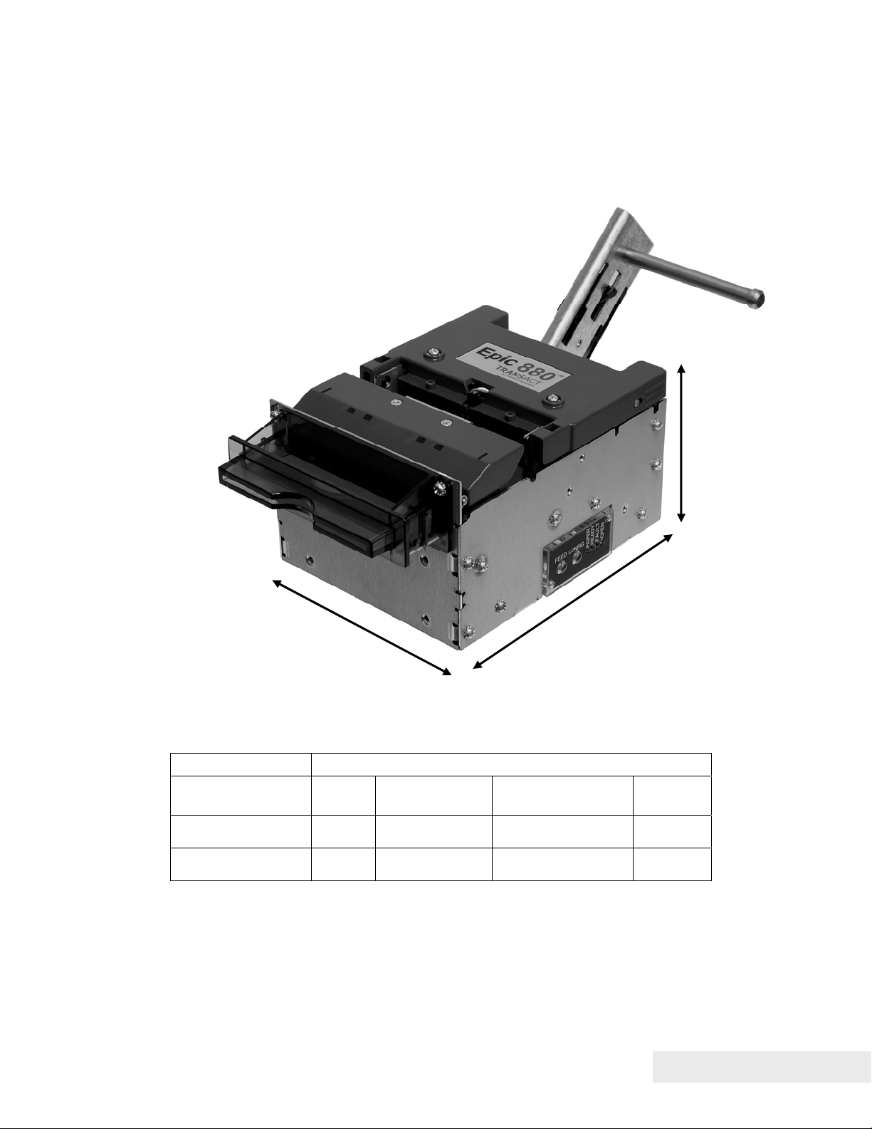
Figure 1. Epic 880TM Printer.
Standard Features
The following features are standard for Epic 880
• Integrated printer mechanism/main controller PCB architecture
• Variable length presenter, capable of handling from 63.5 to 254 mm. (2.5 -10
inches) length tickets
• Full-cut auto-cutter module as part of printer mechanism
• Minimum 150 mm (6.0”)/second print speed (monochrome black text)
• 203 dpi print resolution (8 dots/mm.)
• Special print scalable to 8x with reverse, underscore, italic, and bold print
• 44/57 characters per line for 80 mm paper width
• Face-up print orientation
• ASCII and Unicode character encoding
• Ladder and fence barcode printing supporting UPC-A, UPC-E, EAN13, EAN8,
Code39, ITF, CODABAR, Code93, Code 128, Code31, and Interleaved 2 of 5
• Serial RS232C and USB interfaces built into main controller PCB
• Selectable baud rates
TM
printers:
100-88002 Rev B Page 11
Page 24

Epic 880TM Specifications and Requirements
• Drivers for Windows XP and XPe
• 4 MB minimum flash memory and 8 MB RAM
• Ithaca command set emulation
• Power: 24 VDC
• Power Connector: 4 pin Molex
• Paper Out, Paper Cover-Open, Paper Low, Top-Of-Form, Jam Detection,
Transport Ticket Taken, Head Temperature, and Ticket Retract sensors
• Ticket retract feature
• Power and error LED(s)
• Paper feed button
• Easy paper loading
• Portrait or landscape printing under Windows
• Internal counters to track number of hours on, cuts completed, lines fed, and error
conditions
• Capable of handling a 152 mm. (6.0 inch) diameter, 82.5mm. wide paper roll
• Compliant with RoHS (Restriction on Hazardous Substances)
• Bezel assembly with LEDs (translucent blue)
Optional Features
The following options are available:
• 80mm paper guide
• Lower paper guide
• Additional or custom fonts or character sets.
• Custom emulations (Epson, Custom)
• Universal power supply (100-240 VAC, 47-63 Hz)
Page 12 100-88002 Rev B
Page 25
Epic 880TM Specifications and Requirements
)
(
)
General Specifications
4.70” (119.28mm)
Figure 2. Epic 880TM Dimensions.
Printer Dimensions
Max Dimensions
W D (w/out paper)
Dimensions in
inches
Dimensions in
millimeters
(fully assembled as single unit)
4.77 6.05 7.02 3.48
121.2 153.7 178.2 88.4
6.04” (153.62 mm
D (with paper guide
and w/out paper)
H
3.39”
86.13mm
Weight
Approximate weight 4 lb 1.8 Kg
100-88002 Rev B Page 13
Page 26
Epic 880TM Specifications and Requirements
Interface Type
Bi-directional serial RS-232 or USB
Printer Type
Fixed 80 mm linear thermal head.
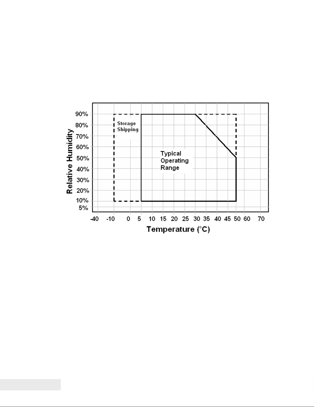
Figure 3. Temperature and Humidity Ranges.
Printer Environmental Conditions
Operating Temperature Range: 5º - 50ºC (41ºF - 122ºF)
Shipping/Storage Temperature Range: –10º - 50ºC (14ºF - 122ºF)
Operating Humidity Range: 10% - 90% non-condensing
Shipping/Storage Humidity Range: 10% - 90% non-condensing (excluding
paper)
Reliability
Printer Life: 10,000,000 print lines
Print Head Life: 100Km. min.
Cutter Life: 1,000,000 cuts (POS Grade)
750,000 cuts (Lottery grade)
Page 14 100-88002 Rev B
Page 27

Epic 880TM Specifications and Requirements
AC Power Requirements
90-264 VAC at 47-63 Hz.
DC Power Requirements
Thermal printers require high peak currents based on how many print elements are
being used and how often. High density printing requires much more current than low
density printing. High density printing in the horizontal axis will put extreme peak
loads on the power supply. These high peak currents can cause power supplies to
sag, roll back or even shut down. A power supply with an average rating sufficient to
meet the average printer requirements many not be sufficient to meet the peak
requirements. The power supply selection is critical to proper printer operation.
Typical power supplies are designed to provide a continuous well regulated voltage at
an average current that does not fluctuate too much and will typically have a wattage
rating based on that average current. A power supply suitable for the Epic 880
could have a wattage rating of 48 watts but unless it can provide peak currents of 8
amps (192 watts) and maintain 24VDC output, it will not function properly.
Some power supplies are designed to provide multiple voltages. These power
supplies typically provide a logic supply voltage that requires close regulation. The
other voltages are not as well regulated or have post regulation. In this case when
the 24 volt output is required to provide high peak currents, the circuitry within the
power supply must maintain the logic voltage and the 24 volt supply will sag. In some
cased the high peak load will actually shut down the complete supply.
Thermal printing has specific power requirements to develop the thermal paper. The
Epic 880
requirements if the voltage is low. The printer will adjust the print element burn time
and that will resulting in increased average current requirements. Input voltage
ranges from about 20 to 27 volts can be accommodated by the Epic 880
input voltage is outside the acceptable range, the printer will issue a fault and will not
function.
A suitable power supply for a thermal printer will provide a constant voltage over a
wide range of loads with a low average current requirement.
Consider the following when selecting or designing a power supply for the Epic 880.
1) It must be able to provide quick response to step loads
2) Current will range widely with peaks at least 4 times the average
3) Load requirements for the power supply are as shown in the table below.
4) Consider a dedicated power supply for the printer.
5) If the printer is expected to print dense graphics, increase the average and
6) Use power cables that are as short as possible and use adequate wire size based
7) Make sure the power supply uses a low ESR capacitor of at least 2200uF and
TM
printer monitors the incoming voltage and will increase its current
TM
continuous current requirements by at least 25%.
on the cable length. Typically AWG 18 is the minimum wire size provided the
length is less than 3 ft (1 m).
preferably larger in the output circuit.
TM
. If the
100-88002 Rev B Page 15
Page 28

Epic 880TM Specifications and Requirements
8) When the printer prepares to print, it will activate the print head power and charge
a bulk capacitor attached to the print head. This current spike can be up to 15
amps for up to 200uS depending on the charge state of the capacitor.
9) Make sure the power supply specification includes any bezel current
requirements.
10) Consider that the frame ground and the 24V return are connected together in the
printer.
11) Use connectors in the power interconnect that are rated for the maximum average
current.
Voltage
Under all line, load and
environmental
conditions
Load Current 0A min
Max. Ripple 240mv p-p
Over voltage Protection < 30V
Over current Protection Output equipped with auto restart short circuit protection
24VDC ±8.5%
1.87A continuous
3.5A continuous - 1 minute maximum.
8A peak load 23.38% duty cycle 2ms period .1A/us slew rate
200 ms maximum
NOTE: This load current does not include the optional Bezel
drive requirement.
< 7amps when t
Table 1. Input Power Requirements
short >10ms
Page 16 100-88002 Rev B
Page 29

Epic 880TM Specifications and Requirements
Power connector
Note: Power may be applied through the 14 pin connector. See the Communications
Interface section for more information.
Note: The 24V RTN and FRAME pins are connected inside the printer.
Test Standards
CE MARK (1998)
FCC CLASS B
EN 60950-1
IEC 60950 (1991) Second Edition with Amendments 1,2,3,4
ROHH/WEEE
Accoustic Noise:
58 dbA average (sound pressure level) while printing a rolling ASCII format.
Microphone positions are at 10 different positions spaced around the printer as
defined in ISO 779.
100-88002 Rev B Page 17
Page 30

Epic 880TM Specifications and Requirements
Printing Specifications
Printing method: Thermal Sensitive Line Dot System
Vertical/Horizontal dot pitch: 0.125 mm.
Resolution: 8 dots per mm (203 DPI)
Line feed pitch: 3.2 mm. (.125 inches)
Print zone (typical) 80 mm (3.15 inches)
Print speed (monochrome): 6 inches per second
Number of print elements: 640 dots in-line
Paper Roll Specifications
Paper Type: One ply thermal paper
Paper Width: 79.5 +/- .05 mm (3.13 +/- .02 inches)
or 82.0 +/- 0.5 mm. (3.23 +/- .02 inches)
Paper Thickness 0.076 mm to 0.09 mm (.0022 to .0035 in.) thick
Roll Diameter: 152 mm (6.0 in.)
Roll Core Inside Diameter: .445 to .635 inches
Roll Core Outside Diameter: .730 to .860 inches
Paper Grades : POS and Lottery grades
Paper Usage Precautions:
Use only specified thermal paper. If other paper is used, print quality, head life, and
cutter life may deteriorate. Contact TransAct customer service for approved papers.
Auto Cutter Position
A full cut auto-cutter is a standard feature with all TransAct® Epic 880TM printers.
Cutter type Guillotine
Media width 82.5 mm. (3.25 inches)
Media thickness range 0.0022 to 0.0035 inch
Cut to line of print 0.38 inch
Cutter life 1,000,000 cuts (POS grade)
750,000 cuts (Lottery grade)
Cut time: Less than 750 milliseconds
Paper Out
A receipt paper out sensor is provided as a standard feature, which senses when
approximately .5 inches length of paper is left on the paper roll.
Page 18 100-88002 Rev B
Page 31

Epic 880TM Specifications and Requirements
Communications Interface
RS232 Serial Communications Interface
The RS232 Serial interface connector is a 14 position Molex Minifit Jr®., part number
39-30-1140, which mates with Molex part number 39-01-2140 or equivalent.
1 2 3 4 5 6 7
8 9 10 11 12 13 14
14-pin Direction Description
Pin 1 - No connect
Pin 2 IN Data Set Ready
Pin 3 - No connect
Pin 4 IN Clear to Send
Pin 5 - Signal Ground
Pin 6 - +24V
Pin 7 - Signal Ground
Pin 8 - +24V
Pin 9 - No connect
Pin 10 - Frame Ground
Pin 11 IN Receive Data
Pin 12 OUT Transmit Data
Pin 13 OUT Data Terminal Ready
Pin 14 OUT Request to Send
Table 2 Serial Interface Pin-outs
Signal Voltage and Current levels
The serial interface meets EIA RS232 interface specifications:
Voltage Levels Max +-15 Volts
Min +- 3 Volts
Mark = Off = -3 to –15 Volts
Space = On = +3 to +15 Volts
Note: Power may be applied through this connector or the 4 pin power connector.
See the DC Power Requirements section for 24 volt power requirements.
Note: GND is the 24V return.
Note: FGND and GND are connected in the printer.
100-88002 Rev B Page 19
Page 32

Epic 880TM Specifications and Requirements
USB Interface
The USB interface supports USB Version 2.0 High speed or full speed. The standard
USB interface is implemented through a standard Series “B” receptacle as defined in
the USB Specification. The printer is self-powered and does not draw power from the
standard type B USB interface cable.
The Standard USB Type B connector has the following pin functions:
Pin Signal
1 Vbus (+5 V dc1) (This is used to select between Interfaces)
2 Minus data
3 Plus data
4 Ground
Note: The standard USB interface does not have enough power to run the printer. It
is not possible to power the printer with the USB cable alone.
USB Configuration
To allow the application to use a virtual serial port or a USB printer port to interact with
the printer, the EPIC 880
Virtual COM port or a USB Printer device. The USB section of the configuration
allows USB Mode, USB Enumeration, and whether the printer will perform a normal
Windows plug and play operation to be configured. The default is printer port, use
description, with Windows PnP on.
You should configure these options based on how you want the printer to perform in
your system. Typically only the Virtual COM or USB printer driver is required: to load
the Transact Virtual COM port driver, disable the USB printer port. Typically you can
use the description as the enumeration ID, representing how the printer is uniquely
identified to the host. If you select a description, all Epic 880’s will be the same, and
you can interchange printers without affecting the port location, subject to the
limitation that no more than one Epic 880 can be connected to the same host. If that
is a requirement, select ID by serial number or allow the ID number to be assigned by
windows based on the connection.
You can also disable the Windows PnP sequence. This will prevent the Windows
system from receiving the printer driver selection sequence. This will allow you to
manually assign a driver to the USB printer connection and not have Windows keep
asking for a printer driver.
The adapter will support a high speed USB interface if the host also supports high
speed. If the host does not support high speed the printer will revert to full speed. It
is possible to disable high speed operation by setting a configuration option. The
printer does not support the USB low speed protocol.
TM
supports both ports, and can be configured to support a
1
The Vbus signal is used to disable the serial port. If the USB is connected the RS232 serial
port is not active.
Page 20 100-88002 Rev B
Page 33

Epic 880TM Specifications and Requirements
The most reliable USB interface is as a USB printing device. The Virtual COM driver
is an added layer of code that allows legacy software to believe it is interacting with a
serial port. Note that a limitation of serial communications port virtualization is that
each version of windows is slightly different, and not all RS232 features are
supported: only features such as receive, transmit and ready/busy are supported,
while other features such as on hook, off hook, ring, and break are not supported.
100-88002 Rev B Page 21
Page 34

Page 35

Chapter 3
Operational Procedures
100-88002 Rev B Page 23
Page 36

This page intentionally left blank
Page 24 100-88002 Rev B
Page 37

Operational Procedures
Operational Procedures
How to Operate the Epic 880TM Printer
Your Epic 880
indicator lights: Paper, Ready, Fault, and Open. These are located on a panel on the
right-hand side of the printer.
TM
printer contains two buttons (FEED and CONFIG) and four (LED)
Figure 4. Control panel with FEED and Diagnostics/CONFIG buttons and indicator lights.
Indicator Lights (LED)
The four Epic 880
• Paper LED Indicates paper status (paper low or out)
• Ready LED Indicates printer activity and non-recoverable errors
• Fault LED Indicates problems and probability of recovery
• Open LED Indicates the cover is open
TM
indicator lights are:
The FEED button
The FEED button will provide various functions, depending upon how long it is
pressed.
Pressing this button will provide one of three functions. The function is timedependent, and the display indicators will change to indicate the next mode, as
follows:
100-88002 Rev B Page 25
Page 38

Operational Procedures
• The feed button is a multifunction button. By pressing and releasing the Feed
button, the printer will feed about 5 inches of paper while printing the printer
firmware version. This is intended to clear the printer and align the next ticket for
print.
• By pressing and holding the feed button for a longer time, two additional features
may be activated. Pressing and holding the button for about two seconds will
enter journal maintenance mode.
• Holding the button for about 4 seconds will enter configuration mode.
To aid in selecting the correct mode, the Fault LED will illuminate as soon as the
button is pressed and indicates that FEED is selected. After about 2 seconds the
Fault LED will go out and the PAPER indicator will illuminate. This indicates that
Journal mode is selected. After about 4 seconds, the Cover LED will illuminate
indicating configuration mode is selected
Page 26 100-88002 Rev B
Page 39

Operational Procedures
The Diagnostics/Config button
The printer has a configuration and diagnostics button on the right side of the printer,
labeled CONFIG.
FEED Button
Diagnostics/Config Button
Figure 5. Location of Diagnostics/Config Button.
The Diagnostics/Config button is a multifunction button. By pressing and releasing
the Diagnostics/Config button, the printer will enter self test mode. This is intended to
verify the printer’s operation.
By pressing and holding the Diagnostics/Config button for a longer time, two
additional features may be activated. Pressing and holding the button for about two
seconds will enter hex dump mode. Holding the button for about 4 seconds will enter
configuration mode.
To aid in selecting the correct mode, the Fault LED will illuminate as soon as the
button is pressed and indicates that self test is selected. After about 2 seconds the
Fault LED will go out and the PAPER indicator will illuminate. This indicates that hexdump mode is selected. After about 4 seconds, the Cover LED will illuminate
indicating configuration mode is selected
100-88002 Rev B Page 27
Page 40

Operational Procedures
Using Self-Test
Self-Test Mode allows you to perform a series of tests to show if the printer is
functioning correctly.
To enter self test, momentarily press
printer.
The Epic 880
performing on-site print evaluations. Others are designed for factory setup by
TransAct.
Once in test mode, the FEED button is used to select the test to be run.
Testing the printer
Use the first three TEST options when verifying basic printer operation. The last three
options are for factory test.
Operation –Ticket Print
The receipt test is the primary test option to use when determining if the printer is
functioning correctly.
The ticket test is mostly used during the early stages of troubleshooting, to eliminate
the possibility that the problem is occurring with the printer. If the printer experiences
a failure, and the error indicator light is activated, call TransAct’s Technical Support
department.
Operation – Head Test
This test performs a test pattern that will print all the head print elements and verify
that the drive roll is free from defects or debris. The print head has two heating
elements per dot position. A print element is not considered bad unless both
elements are missing. If the head test shows that there is an inconsistency in the
print there may be debris on the drive roll. If debris is indicated, cleaning the drive roll
should correct the problem. If this does not correct the problem, contact TransAct’s
Technical Support department.
Operation – Marker Calibration
The printer is equipped with several sensors in the paper path, which are adjustable
and will handle a wide range of paper under normal operation. However, if there
appear to be problems associated with any sensor’s operation, the Marker Calibration
test will attempt to adjust the sensors for optional operation with the paper installed.
The Top-of-Form, Paper Out and Jam sensors will be recalibrated. To run this test,
2
the Diagnostics/Config button on the side of the
TM
has several Self-Test options. Some are designed to be useful when
2
The Diagnostics/Config button is a multifunction button. By pressing and releasing the
Diagnostics/Config button, the printer will enter self test. By pressing and holding the
Diagnostics/Config button for a longer time, two additional features may be activated: pressing
and holding the button for about two seconds will enter hex dump mode, and holding the
button for about 4 seconds will enter configuration mode. To aid in selecting the correct mode,
the Error LED will illuminate as soon as the button is pressed and indicate that self test is
selected. After about 2 seconds the Error LED will go out and the PAPER indicator will
illuminate, indicating that hex dump is selected. After about 4 seconds, the Cover LED will
illuminate, indicating that configuration mode is selected.
Page 28 100-88002 Rev B
Page 41

Operational Procedures
simply select it. The printer will automatically position the paper and adjust the
sensors. If the paper installed does not have black dot markings, the Top-of-Form
sensor will be adjusted based on the white level of the paper only.
Factory Test
The printer is equipped with several factory test modes. These test options are only
used for factory burn-in and testing.
Operation – Continuous
Operation – Burn-in
Operation – Rolling ASCII
100-88002 Rev B Page 29
Page 42

Operational Procedures
Level 0 Diagnostics
Level 0 diagnostics are only run at power up, e.g. when power is first applied. These
diagnostics perform the following tasks:
Power On
1. Basic System Integrity
2. Vector Integrity
3. RAM Test
4. Flash Boot Loader Integrity
5. Flash Firmware Integrity (NOTE: If the firmware is corrupted, the printer will remain in boot load.)
6. USB Controller Diagnostics and verify.
7. Start Normal Firmware
8. Verify Configuration Integrity
9. Interface Configuration
10. File System Integrity
11. Start Kernel, Verify Multitasking, Start Tasks
Once the kernel is running, the following tests must pass to allow operation. However, if any
test fails (except the knife home test), the remaining tests will generate recoverable faults and
normal operation will start as soon as the fault is cleared. These tests are also run when
operation is resumed from OFF.
12. Cover Closed Check
13. Knife Home
14. Paper Present
15. Clear Paper Path.
16. Place Printer On-line, Start Normal Operation
The first phase of testing consists of step 1-5, and determines that the boot loader is
accurate and the printer firmware is correct. Tests 1 through 4 produce nonrecoverable errors if they fail, in which case the power must be removed from the
printer and the printer returned for service. If the boot loader is intact, but the main
firmware is corrupted, the printer automatically enters boot loader mode, where the
firmware can then be reloaded into the printer.
Boot Loader Mode
The boot loader may be entered during normal operation through special commands.
Normal boot load operation is by manually starting boot load mode. Boot loader mode
can be entered in one of three ways: (1) when Level 0 Diagnostics finds that the
firmware check (also known as a cyclical redundancy check, or CRC) is bad, (2)
manually, or (3) through the use of a special boot load command.
To manually enter the boot loader, hold the Diagnostics button in the side of the
printer while the power is applied. The FAULT Indicator comes on, and the READY
indicator blinks. At this time, the firmware boot program is operating and the boot
load file may be sent to the printer. When the printer receives the boot load file, the
printer will automatically restart if the firmware load was successful. If the load fails,
the printer will remain in boot load mode. If the load fails, reset the printer by removing
the power and restarting it, and then try again.
Note: In this download mode, the printer will only accept data on the serial port. A
second level loader, described in more detail in the command section of the
TM
880
OEM Integration Manual
Page 30 100-88002 Rev B
, supports the USB interface.
Epic
Page 43

Operational Procedures
Note: In rare cases, it may be required to load the firmware twice. The Epic 880TM
contains a flash file system. The complete flash image is sometimes distributed as
part of a firmware update. If the file system image is not compatible with the previous
firmware configuration, the new firmware may need to reformat the file system. If this
occurs, the firmware will have to be reloaded after the flash is reformatted. The
indications that this is happening will be an excessively long startup after a firmware
update after which the printer will not print: tickets are presented, however only
graphics are printed, and fonts will be missing. In this case it is important that the
reformat be allowed to complete, as it can take up to 30 seconds to reformat the
entire flash system.
Printer Status LED’s
The Epic 880TM printer has four indicator lights to indicate various operating states of
the printer. In general these are Fault, Cover Open, Paper Status, and Ready.
The printer may be in normal operation, self test or in one of two boot load modes.
The Ready and Fault indicators will indicate which mode by a unique blink pattern:
TransAct Boot Load Mode
In TransAct Boot Load Mode, the power LED will blink slowly with a 50% duty cycle.
It will repeat this cycle about every 2 seconds (1 Sec on, 1 Sec off). There will be a
red indication on the Error LED indicator until the down load is started.
Self Test Mode
When the printer is in Self Test Mode, the power indicator will blink slowly with a 50%
duty cycle at a 2 second rate. This is very similar to TransAct Boot Load Mode,
however, the red error indicator will not be present.
Normal Operation
During Normal operation, the Power LED will remain on unless an error is being
indicated. There are two classes of errors, soft errors and hard errors. Soft errors are
recoverable without power cycling the printer; conversely, recovering from hard errors
requires removing the power from the printer, correcting the problem, and then
reapplying power.
Status LED response
Power On, Printer Ready Ready LED on (Not Blinking)
Paper Low Paper LED Blinking
Soft Errors
Soft errors may be recovered by the host, or by opening and closing the printer cover.
Each of these errors is indicated by a 5 second repeating blink pattern on the Power
LED with the red Fault LED continuously on.
Out of Paper 2 Blinks Paper LED will also be on.
Cover Open
3
4 Blinks
3
The printer may be configured to beep if the cover is open.
100-88002 Rev B Page 31
Page 44

Operational Procedures
Jam Detected 5 Blinks
Missed Top of Form 6 Blinks Paper LED will blink fast.
Illegal or Bad Command 7 Blinks Paper LED will blink fast.
Printer Over Temp 8 Blinks Fault LED will blink slow.
Bad Power 8 Blinks Fault LED will blink fast.
Hard Errors
Hard errors have a similar blink pattern to soft errors, except that they are slower and
repeat every 10 seconds. In general, these errors occur during level 0 diagnostics
and are not recoverable. In these cases, the Error and Power LEDs will blink at the
same time.
EEPROM read fault 2 Blinks
EEPROM write fault 3 Blinks
Error Vector Taken 4 Blinks
Knife Error 5 Blinks
User Store Format Error 7 Blinks
User Data Store Error 8 Blinks
Flash Read/Write Error 9 Blinks
Memory Error 12 Blinks
Com Adapter 14 Blinks
Kernel Fault 15 Blinks
File system Fault 16 Blinks
Auto Error Recovery
The Epic 880TM printer has the ability to auto recover from some internal errors.
Flash Format Errors
The internal flash that is used to store graphic images is formatted to assure data
integrity. If this format is corrupted, the printer will automatically delete and reformat
the flash. The host can then reload the images.
Input Power Fault
The printer monitors the power input to the printer. If it is found to be greater than 26
volts or less than 20, the printer will stop and wait for the power to return to
specification.
Head Temperature Fault
The printer monitors the head temperature. If the head temperature is greater than
60º C, the printer will start to slow down. If the head exceeds 65º C, the printer will
stop. The printer will heat the head to maintain a head temperature of 25º C. If the
printer cannot maintain a head temperature of 0º C, the printer will stop. In all cases,
the printer will automatically recover when the head temperature is within range.
Configuration Fault Recovery
The printer maintains an operating configuration in EEPROM. Information such as the
printer’s serial number, operating configuration, and running totals are stored in this
memory. Each section of this memory maintains a check character to signal that the
data is valid. If this memory is found to be corrupted, the printer will restore it based
on a backup copy saved in flash. This flash copy is generated when the printer was
Page 32 100-88002 Rev B
Page 45

Operational Procedures
electronically configured using the TransAct® configuration tool. Any configuration
parameters altered during normal operation will not be saved in the flash copy. The
EEPROM will be restored to the value set by the configuration program.
100-88002 Rev B Page 33
Page 46

Operational Procedures
Loading Paper
The Epic 880 printer uses a continuous roll of POS or Lottery grade thermal paper,
with specifications outlined in the chapter
Requirements
Epic 880TM Specifications and
.
Figure 6. Auto-feeding a Paper Roll.
Instructions for auto-feeding the paper are as follows:
1. Place a roll of new paper on the spindle, with the end of the paper unloading from
the back to the front of the printer, as shown in the figure.
2. Thread the free end of the paper under the top cover as shown.
3. Push the end of the paper forward until it engages the Paper Out sensor, located
under the center of the top cover.
4. Paper will feed automatically, and then print and eject a test ticket.
Cleaning the Print Head
Once the unit is opened, the paper path is accessible for cleaning or clearing paper.
Use a soft brush to clean the paper dust from inside the printer. The paper dust
should also be removed from the sensor optics. If streaking on the printed ticket is
evident, the thermal print head may need to be cleaned. This can be with a cotton
swab moistened with an alcohol solvent (ethanol, methanol, IPA).
Page 34 100-88002 Rev B
Page 47

Operational Procedures
Warning: After printing, the print head can be very hot. Be
careful not to touch it and let it cool down before you clean it.
Do not damage the print head by touching it with your fingers or
any hard object.
100-88002 Rev B Page 35
Page 48

Page 49

Chapter 4
Configuring Your Epic 880TM Printer
100-88002 Rev B Page 37
Page 50

This page intentionally left blank
Page 38 100-88002 Rev B
Page 51

Configuring Your Epic 880TM Printer
Configuration Mode Overview
There are two ways to configure the Epic 880TM printer: the first is to use the manual
configuration sequence by using the CONFIG and FEED key, and the second is to
use TransAct’s remote configuration software. TransAct Technologies offers the use
of a remote CONFIG program as a fast, easy way for system integrators to configure
or reconfigure your Epic 880
TM
printer. To obtain more information, or the latest
version of the CONFIG program, call TransAct’s Sales Department or Technical
Support.
Most Frequent Configuration Incompatibilities
• Emulation
• RS-232 Serial Interface (baud rate)
How to Change Configuration Settings
Entering into Configuration Mode
1) Press the CONFIG
2) Select configuration mode.
3) Follow the printed instructions.
• Press and hold the FEED button for the next option.
• Press and Release the FEED button to change the option.
• Power cycle to exit without changing.
• Press CONFIG to save and Exit
After you enter Configuration Mode, the printer will print the current configuration, the
current totals and the error logs, if any. Save this printout as a guide to changing the
configuration. It’s also useful in case you wish to return the printer to the previous
configuration.
Each emulation may have different configurable features. If you are changing the
emulation, note that the printout that was printed at the beginning of the configuration
process may be incorrect for the new emulation, and the configurable features may be
different. If you are using this printout as a configuration guide, and you are changing
the emulation, you may wish to save the new emulation and then re-enter
Configuration Mode to change other options. This will print all the available features
for the new emulation.
4
button for approximately 4 seconds.
4 The CONFIG button is a multifunction button. By pressing and releasing the CONFIG
button, the printer will enter self test. By pressing and holding the CONFIG button for a longer
time, two additional features may be activated: pressing and holding the button for about two
seconds will enter hex dump mode, and holding the button for about 4 seconds will enter
configuration mode. To aid in selecting the correct mode, the Error LED will illuminate as soon
as the button is pressed and indicate that self test is selected. After about 2 seconds the Error
LED will go out and the PAPER indicator will illuminate, indicating that hex dump is selected.
After about 4 seconds, the Cover LED will illuminate, indicating that configuration mode is
selected.
100-88002 Rev B Page 39
Page 52

Configuring Your Epic 880
gy
Setting up for Color Paper
The Epic 880
quality, the printer should be configured to print the paper being used. If the paper you
are using is included in the list of papers displayed during printer configuration, that
configuration should be used. If not, the printer should be set to Generic Color. If this
does not produce acceptable print quality, you may select Custom Color.
Custom Color
When using Custom Color, start with a read setting of about 0.12 mJ/sq.mm and a
black energy of 0.24 mJ/sq.mm. First, adjust the black level to produce acceptable
black print.
TM
Printer
TM
may be configured to print two color thermal paper. For good print
DO NOT EXCEED 0.40 mJ/sq.mm, or the paper may start to
stick to the print head and cause paper jams. Setting the Black
energy too high will also slow the printer down. All color papers
tested by TransAct will operate with black levels less than 0.35
mJ/sq.mm. When the Black energy is set, adjust the Color
value.
NEVER exceed the Black ener
with the Color energy.
The color level can be very critical. Do not attempt to
make the color darker by increasing the energy to the
point where black starts to appear, the print quality will
not be consistent.
Remote Configuration
Remote configuration is provided for all printers, and is accessed through a series of
extended diagnostic and configuration commands. The TransAct
®
universal
configuration program will allow the configuration to be read, edited, and written back
to the printer. It will also allow the configuration of one printer to be recorded and
replicated over a number of printers. The program is available from TransAct
Technical Support or by downloading it from the Internet – consult the section On-line
Technical Support for further details.
Remote Boot Load
The Epic 880
field updates of the printer’s firmware. This loader is started by command and then a
TransAct
successfully received by the remote boot loader, the printer will automatically reset
and operate with the updated code. If the firmware update fails for any reason, the
printer will remain in Remote Boot load mode until a successful load is accomplished.
TM
printer is equipped with a special boot loader feature that will allow
®
firmware load image is sent to the printer. When the load image is
Page 40 100-88002 Rev B
Page 53

Configuring Your Epic 880TM Printer
Field Configuration Feature
A field configuration feature allows easy setup and configuration of your Epic 880
printer. This feature provides a one-time prompt, on initial power-up, that lets you
select from a number of configurations that are pre-loaded for you at the factory.
This feature is an option, and must be set up and activated by TransAct. It stores a
specified number of complete, commonly-used configurations in the printer, together
with a text description and configuration summary.
Using Field Configuration
When the FEED button is pressed for over 6 seconds, the printer will either enter field
configuration mode or comprehensive configuration mode, depending on whether the
field configuration feature is present.
The initial print out will be as shown in Figure 7:
There are x
stored configurations
to select from.
Press and release FEED
to move between options.
Press and hold the
FEED button to select
an option.
Press DIAG Button
Or Cycle Power
To Exit
Figure 7. Startup message in Field Configuration mode.
Note: The “x” value shown in this figure will be the actual number of loaded
configurations, and can range from 2 to 20.
The first option presented is an option to print all the stored configurations in summary
form. Press and hold the FEED button after this option is displayed to select it. This
summary includes the configuration name, a text description and a brief list of
features for each pre-loaded configuration.
After the “Print all option”, each configuration is sequentially presented by name with
its description. Press the FEED button once to move to the next configuration in the
100-88002 Rev B Page 41
Page 54

Configuring Your Epic 880
list, or press and hold the FEED button to select the displayed configuration. A sample
configuration is shown in Figure 8.
Once a selection is made, a summary will be printed, and the user will be asked to
confirm the selection by pressing the FEED button. If not confirmed, the printer resets
and the process starts over. The printer will not exit this mode until one of the
predefined configurations is selected and accepted.
If confirmed, the selected configuration is recorded in the printer and made active,
after which the printer then resets. Once a selected configuration is activated, the
configuration will remain active until changed.
Note: It is possible to require that a configuration be activated before the printer can
be used. In this case the printer will request a configuration be selected every time it
is turned on until a valid configuration is actually selected. At that time the printer will
operate normally.
TM
Printer
ID: xxxxxxx
Configuration description:
Ithaca normal with transport
Configuration Summary:
Emulation
Emulation mode -Ithaca PcOS
Paper Selection
Print Energy Control:
Paper -Generic Black
RS232 Serial Interface
Baud Rate : 19200 BPS
Mode : 8 Bit No Parity 1 Stop Bit
Handshaking : Ready/Busy
Receive Error : Prints ‘?’
DTR/RTS Signal : RTS and DTR
CTS/DSR Signal : None
General Options
Code Page : 437
CPI : 17
Carriage Return : Normal
Off-Line Option : Normal
Line Spacing : 8.1 LPI
Input Buffer : 8192 Char.
And so on
Figure 8. Sample pre-loaded configuration.
Page 42 100-88002 Rev B
Page 55

Chapter 5
Mounting Requirements
100-88002 Rev B Page 43
Page 56

This page intentionally left blank
Page 44 100-88002 Rev B
Page 57
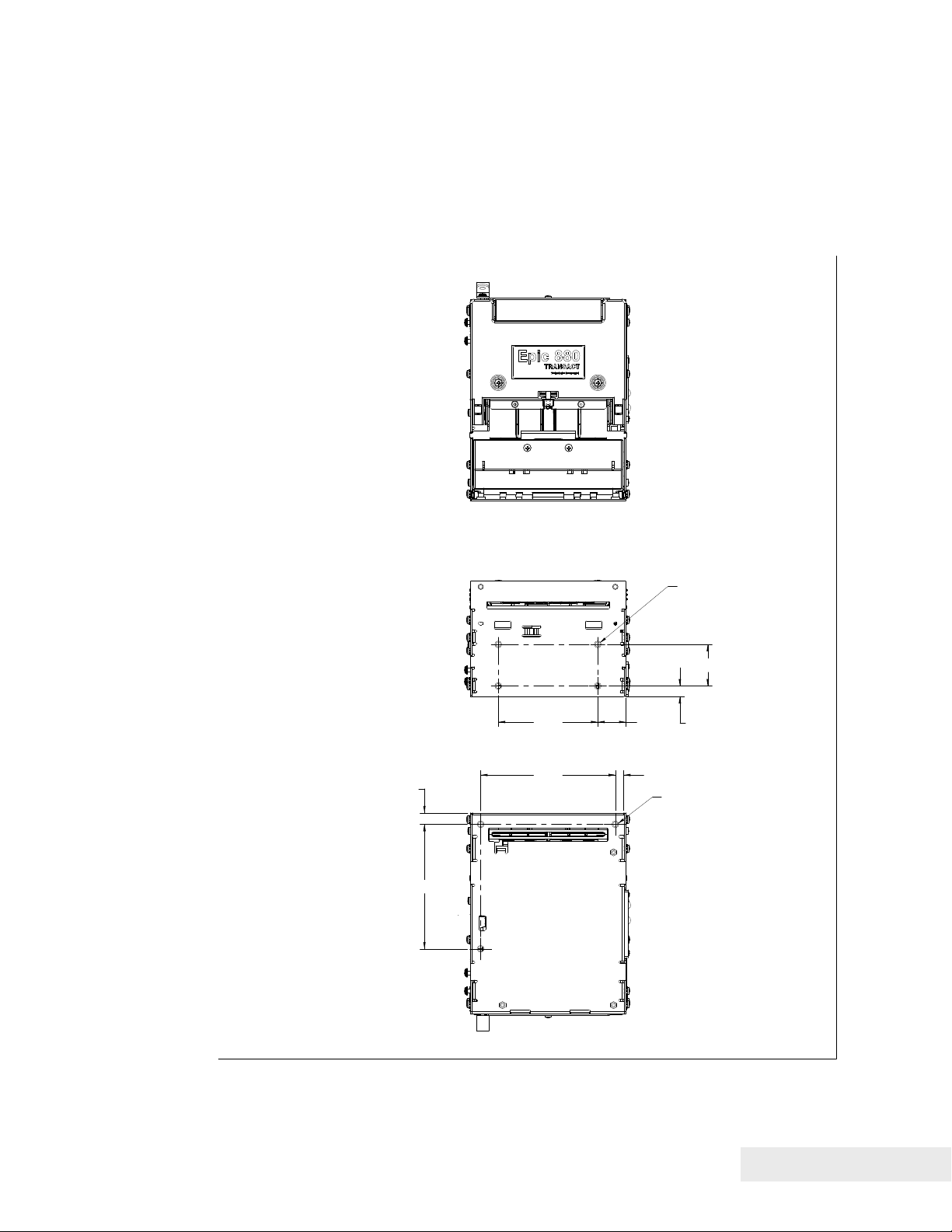
Mounting Requirements
Mounting Requirements
The compact Epic 880 design architecture can be easily configured into end
applications, and has multiple mounting points. (Note: All dimensions are
shown in inches, and printer is shown without bezel and paper
bracket/spindle)
.35
3.75
.853.00
M4-4PL
1.25
.31
.254.06
M4-3PL
Figure 9. Epic 880TM Mounting Locations
100-88002 Rev B Page 45
Page 58

Mounting Requirements
Bezel Mounting Specifications
Bezel to Printer Mechanism mounting points
Epic 880
mounted following the hardware and mounting dimensions as listed. The
following drawing shows the positioning and dimensions of the Epic 880
bezel’s mounting points.
Front: 2x M3x 0.5 screws and interface with custom bezel.
TM
printers are designed to accommodate a bezel assembly that is
M3 MOUNTING
SCREW - 2PL
TM
4.060
1.100
BOSS - 2PL
.090
MOUNTING
Bezel view
Figure 10. Bezel Mounting and Hardware Requirements
Page 46 100-88002 Rev B
Page 59

Mounting Requirements
Spindle Mounting Options
The Epic 880
the left side of the printer or one of four locations on the control panel side.
The following figures show typical mounting locations and cable dressing
options.
45˚ Up Spindle Mounting
TM
spindle assembly can be mounted in one of five locations on
Pivot and Locating
Screws
Paper Spindle
Bracket
Figure 11. 45˚ Up Spindle Location
Figure 11 shows the 45˚ Up spindle position with the arm at a 45˚ angle up.
Note the location of the pivot and mounting screws.
100-88002 Rev B Page 47
Page 60

Mounting Requirements
Straight Back Spindle Mounting
Figure 12. Straight Back Spindle Location
Figure 12 shows the straight back spindle position. Note the location of the
pivot and mounting screws.
Pivot and Locating
Screws
Paper Spindle
Bracket
45˚Down Spindle Mounting
Pivot and Locating
Screws
Paper Spindle
Bracket
Figure 13. Angle Down Spindle Location
Figure 13 shows the angle down spindle position with the arm at a 45˚ angle
down. Note the location of the pivot and mounting screws.
Page 48 100-88002 Rev B
Page 61

Mounting Requirements
Straight Down Center Spindle Mounting
Paper
Guide
Paper Spindle Bracket
Pivot and Locating
Screws
Figure 14. Straight Down Center Spindle Location
Figure 14 shows the straight down center spindle position with the arm at a
90˚ angle down. Note the location of the pivot and mounting screws. This
location requires that the paper guide be mounted to the printer to assure that
the cabling does not interfere with the paper path.
Note: The printer is larger with the paper guide installed.
100-88002 Rev B Page 49
Page 62

Mounting Requirements
Straight Down Rear Spindle Mounting
Paper Guide required
for this orientation
Pivot and Locating
Screws
Paper Spindle Bracket
Figure 15. Straight Down Rear Spindle Location
Figure 15 shows the straight down rear spindle position with the arm at a 90˚
angle down. Note the location of the pivot and mounting screws. This location
requires that the paper guide be mounted to the printer to assure that the
cabling does not interfere with the paper path.
Note: The printer is larger with the paper guide installed.
Control Panel Side Spindle Mounting
All five positions can be duplicated on the control panel side of the printer with
the exception of the straight down center location shown in
control panel occupies that location.
Page 50 100-88002 Rev B
Figure 14 as the
Page 63

Mounting Requirements
g
Retract Opening
When mounting the Epic 800
retract opening located on the underside of the front of the unit as shown.
TM
printer, clearance must be allowed for a ticket
Retract openin
Figure 16. Retract Opening.
The dimensions of this opening are as shown in Figure 17.
100-88002 Rev B Page 51
Page 64

Mounting Requirements
Figure 17. Dimensions for Retract Opening.
Page 52 100-88002 Rev B
Page 65

Chapter 6
Printer Sensors
100-88002 Rev B Page 53
Page 66

This page intentionally left blank
Page 54 100-88002 Rev B
Page 67

Printer Sensors
p
A
p
p
Printer Sensors
The Epic 880
as pictured in the figures below.
nti-Jam Sensor
Pa
er Out Sensor
-of-Form Sensor
To
TM
printer uses several sensors to provide feedback to the host system,
Cover-Open
Switch (inside)
Pa
Figure 18. Sensor Breakdown and Locations.
er Low Sensor
Paper Out Sensor
A Paper Out Sensor, mounted to the Lower Paper Guide, optically senses a Paper
Out flag located in the ticket path. When the sensor detects the flag, it indicates that
the ticket roll is depleted.
Cover-Open Switch
A Cover-Open Switch, mounted to the inner left side plate, is activated when the Top
Cover is closed and the latch depresses the switch arm. When the Top Cover is
opened, the Cover Open switch trips, and the printer goes off-line.
Top-of-Form Sensor
A Top-of-Form Sensor is mounted in the paper path, and senses a pre-printed black
dot (if present) on the ticket stock. This black mark is used to position the paper for
printing on a preprinted form. Typically the ticket is pre-positioned to the Top-of-Form
and when the ticket is complete, the paper is fed to the Top-of-Form and then cut.
100-88002 Rev B Page 55
Page 68

Printer Sensors
Paper Low Sensor
The Epic 880TM has a Paper Low Sensor. This sensor is mounted to the paper
spindle and will provide an indication that the paper is getting low. The length of
paper remaining when paper low is sensed is dependent on the paper roll core
diameter.
Anti-Jam Sensor
An Anti-Jam Sensor is mounted to the knife frame, and senses the presence of a
ticket immediately before and after a knife cut. Under normal conditions, right after a
knife cut, a ticket is fed into the transport and presented to the customer. If a ticket is
not fed properly into the transport (for example, when a ticket jams) the Anti-Jam
Sensor detects the jammed ticket and stops printer operation.
Transport Ticket Taken Sensor
A Ticket Taken Sensor, mounted in the Ticket Transport, is used to detect the lead
edge of the ticket as well as determine when customers have actually taken the
printed ticket.
Transport Ticket
Taken Sensor
Figure 19. Transport Ticket Taken Sensor.
Page 56 100-88002 Rev B
Page 69

Printer Sensors
Transport Ticket Retract Sensor
The Ticket Retract Sensor, mounted in the Ticket Transport retract path, is used to
detect the presence of the ticket in the retract path. Under normal operation, the
retract path should be clear after the retract.
Transport Ticket
Retract Sensor
Figure 20. Transport Ticket Retract Sensor.
100-88002 Rev B Page 57
Page 70

Page 71

Chapter 7
Electrical Connections
100-88002 Rev B Page 59
Page 72

This page intentionally left blank
Page 60 100-88002 Rev B
Page 73
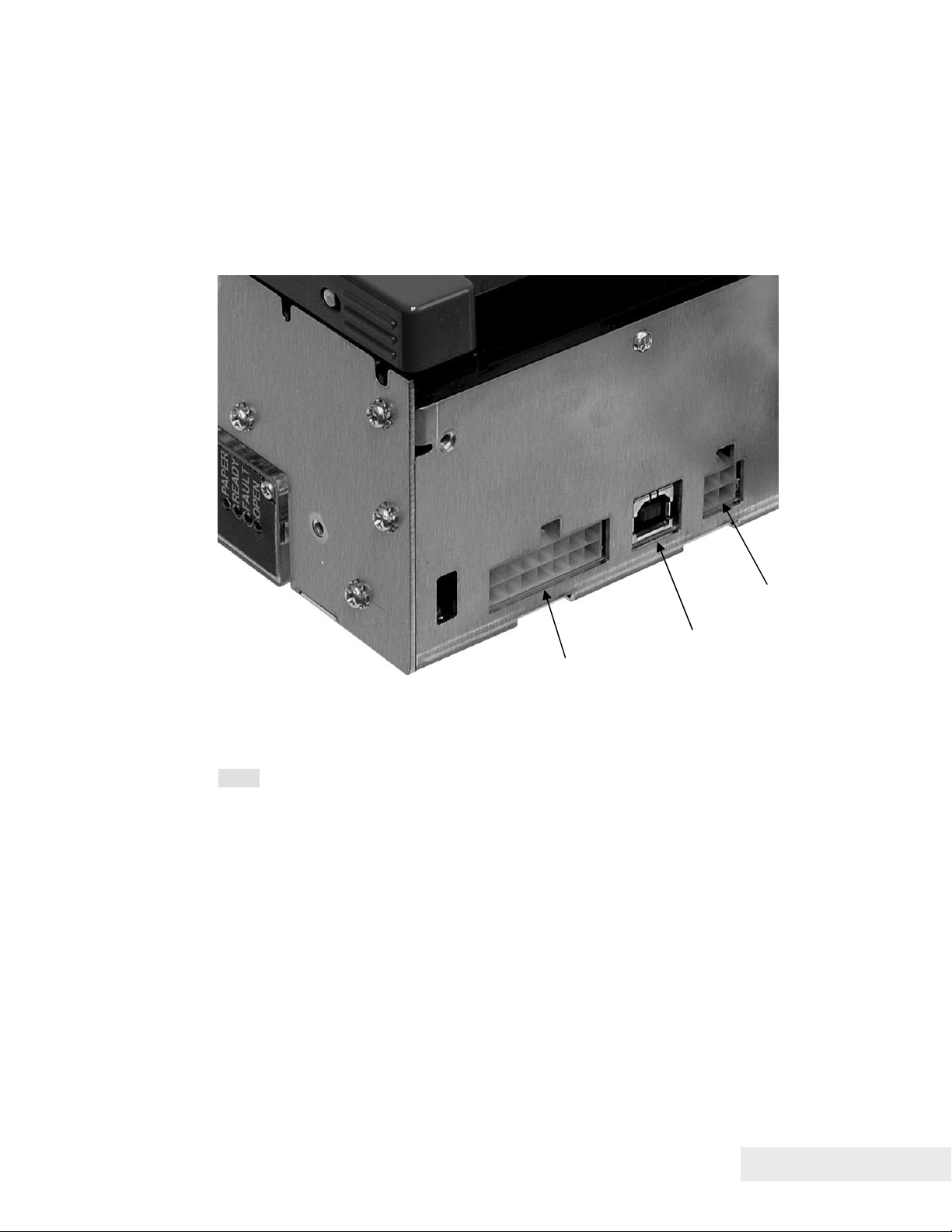
Electrical Connections
Communications Interface
USB and RS-232 communications are supplied through interface connections
at the rear of the printer, as illustrated in the figure. The Serial RS-232
interface connector is a locking Molex connector and the USB interface is a
standard USB B connector. Power is supplied through a locking 4-pin Molex
connector as shown.
Power connector
USB port
Serial communications port
Figure 21. Communication PCB Location and Connector Info.
Note: Pin-out configurations for these interfaces are documented in Chapter 2,
Epic 880
TM
Specifications and Requirements.
100-88002 Rev B Page 61
Page 74

Electrical Connections
Cable connection locations
Figure 22 Power and RS232 Left hand Exit
Figure 23 Power and USB Left hand Exit
Note that the Power and communications cables can also be routed to the
right. The unused mounting location in the upper right corner should be used
to restrain the cables in a similar fashion as the left exit.
Page 62 100-88002 Rev B
Page 75

Electrical Connections
Printer Block Diagram
100-88002 Rev B Page 63
Page 76

Page 77

Chapter 8
Control Codes
100-88002 Rev B Page 65
Page 78

This page intentionally left blank
Page 66 100-88002 Rev B
Page 79

Control Codes
Control Codes Overview
This OEM Integration Manual is designed to help users of the Epic 880TM printer
develop applications. Because Epic 880
printers with several features not normally found on general-purpose printers, they
have unique control codes that are documented in this manual.
TM
printers are specialized point-of-sale
Nomenclature
When describing control codes, confusion often occurs as to whether the description
is decimal, hexadecimal, or ASCII. To minimize the problem, this OEM Integration
Manual uses the following nomenclature when describing control code sequences.
[ ] Encloses a control character. [ ] represents a single, 8-bit value as
defined in the standard ASCII tables. The ASCII Code Table in
Appendix B lists the control codes. An example would be [ESC], which
would represent a 1BH or 27 decimal.
< > Encloses an 8-bit value in decimal format. The value is from zero to
255. An example is <2>, which represents 02H or 2 decimal.
<n> Indicates a variable parameter. The variable parameter, <n>, can have
a value from zero to 255. The meaning of <n> is described and defined
in the description of the command.
<n
> <n2> Indicates that there are two parameters, <n1> and <n2>, where both
1
can have values from zero to 255.
<m
> <m2> Is an TransAct® Printer Control Language (IPCL) parameter consisting
1
of two digits where <m
nine. The parameter is combined to form a value from zero to 99. If
<m
> is included, the parameter is combined to be from zero to 999. If
3
two values are specified, there must be two bytes added to the IPCL
code. That is, if the command specifies <m
value is five, it must be specified as 05.
X All other characters in control strings represent ASCII characters. For
example, [ESC] 1 represents 1BH followed by 31H.
In many cases, applications require that control sequences be specified in
hexadecimal or decimal codes. In most cases, commands are specified in ASCII,
hexadecimal, and decimal. The ASCII Code Table in Appendix D lists ASCII,
hexadecimal, and decimal equivalents.
> and <m2> are ASCII characters from zero to
1
> <m2> and the desired
1
100-88002 Rev B Page 67
Page 80

Control Codes
Standard Emulation
The standard control codes for the Epic 880TM Printer are extensions and subsets of
the PcOS emulation provided on other TransAct
The Epic 880
language, as well as a Custom VKP80 emulation capability. For details about these
emulations, contact TransAct Technical Support.
IPCL Codes
TransAct® Printer Control Language (IPCL) codes are part of PcOS and designed to
control a printer without using control characters (i.e. characters less than 20H). Only
the standard PcOS emulation supports IPCL.
In rare cases, an IPCL code will interfere with the text that is to be printed. The IPCL
translator can be disabled with an [ESC] y <4> command.
Other Emulations
The Epic 880TM Printer supports a basic Epson emulation.
Note: Specific EPSON compatibility features, such as its Automated Status
Back (ASB) feature, are available as an option from TransAct
Technologies. Command codes pertaining to these features are
documented as “licensed” within the command description.
It is intended that the standard TransAct
applications. Not all features of Epic 880
emulations.
®
products.
TM
printer also supports an emulation of the Epson ESC/POS control
®
PcOS emulation be used for new
TM
Printers are supported by other
Application Development
To aid application development, several chapters in this manual are designed to help
the programmer understand the Epic 880
detailed description of each of the commands. Subsequent chapters provide
explanations of how the printer works, including a description of the internal print
buffer, communications link, and interaction between the host computer and printer.
TM
Printer. The next chapter provides a
TransAct Control Codes and Commands
Throughout this OEM Integration Manual, charts and tables list commands and
features. In most cases, the charts cross-reference the page that describes the
command. Code summary charts, arranged by code and function, are provided to
help quickly find commands.
PcOS Printer Control Codes
The following section defines the Epic 880TM TransAct® PcOS emulation. The native,
TransAct
is consistent with most previous TransAct
the printer is placed in a new application. Alternatively, an emulation is offered for the
Epson ESC/POS language, as well as a customer emulation; contact TransAct
Technical Support for further information on these options.
Page 68 100-88002 Rev B
®
PcOS emulation provides the most flexibility and control over the printer. It
®
PcOS products, and should be used when
Page 81

Control Codes
TransAct does not recommend that you generate drivers for emulations other than
PcOS. In addition, TransAct has created several tools that can be used to generate
and maintain graphic images and files for print on the Epic 880
drivers and tools are available on the TransAct web site and on a
Developer’s Toolkit
. For more information about either of these options, contact
TM
. Information about
TransAct® Software
TransAct Technical Support.
100-88002 Rev B Page 69
Page 82

Control Codes
{
Quick PcOS Reference Chart
Description ASCII Hex
IPCL
Page
equivalent
code
Low Level paper Motion
Line feed. [LF] 0AH &%LF 76
Carriage return. [CR] 0DH &%CR 76
Horizontal Motion
Back space. [BS] 08H &%BS 77
Horizontal tab. [HT] 09H &%HT 77
Set horizontal tab stops. [ESC] D <n1> <n2>
1BH 44H none 77
... <ni> <0>
Set horizontal position. [ESC] n <n1> <n2> 1BH 6EH &%HP<m1>
> <m3>
<m
2
Set justification.
n=0 Left
n=1 Center
[ESC] a <n> 1BH 61H &%JR
&%JC {n=1}
&%JL {n=0}
n=2}
78
78
n=2 Right
n=8 Left (No line feed)
n=9 Center (No line feed)
n=10 Right (No line feed)
Reset horizontal and vertical tab
[ESC] R 1BH 52H &%HV 78
stops.
Set left/right print margins.
[ESC] X <n1><n2> 1BH 58H none 154
n1 = Left margin, n2 = Right margin
Select minimum character height
[ESC] + P<w><h> 1BH 50H none 215
and width in points
Select minimum character height
[ESC] + p<w><h> 1BH 70H none 216
and width in ¼ points
Vertical Motion
Perform a fine line feed.
[ESC] J <n> 1BH 4AH &%FM <m1>
> <m3>
<m
2
79
Set 1/8-inch line spacing. [ESC] 0 1BH 30H &%ST 79
Set 7/72-inch line spacing. [ESC] 1 1BH 31H &%SG 80
Begin variable line spacing.
[ESC] 2 1BH 32H none 80
(Enable [ESC] A <n>).
Set variable line spacing to n/216
inch.
Set variable line spacing to n/72
[ESC] 3 <n> 1BH 33H &%SV <m1>
<m
> <m3>
2
79
[ESC] A <n> 1BH 41H none 80
inch.
Set Line spacing in points [ESC]+V<n> 1BH 2BH 56H None 215
Set Line spacing in ¼ points [ESC]+v<n> 1BH 2BH 76H None 216
Select minimum character height
[ESC] + P<w><h> 1BH 50H none 215
and width in points
Select minimum character height
[ESC] + p<w><h> 1BH 70H none 216
and width in ¼ points
Feed <n> lines at current spacing. [ESC] d <n> 1BH 64H &%FL <m1>
<m
>
2
Set vertical tab stops. [ESC] B <n1> <n2>
<n
>...<ni> 0
3
1BH 42H none 83
82
Vertical tab. [VT] 0BH &%VT 82
Form feed. [FF] 0CH &%FF 83
Feed to black dot [ESC][VT] 1BH 0BH None 86
Page 70 100-88002 Rev B
Page 83

Control Codes
Description ASCII Hex
IPCL
Page
equivalent
code
Set top of form. [ESC] 4 1BH 34H &%TF 84
Set form length in lines. [ESC] C <n> 1BH 43H
Begin auto line feed. (n=0, end n=1) [ESC] 5 <n> 1BH 35H
Set form length in inches. [ESC] C [NUL] <n> 1BH 43H
&%SL <m1>
<m
>
2
&%CA {n=0}
&%MA {n=1}
&%SI <m1>
<m
>
2
84
85
84
Transport Control
Set Transport Mode [ESC]i<f><v> 1BH 69H None 152
Feed Transport [ESC]j<n> 1BH 6AH None 152
Deliver ticket from transport [ESC]k 1BH 6BH None 152
Transport ticket retract [ESC]m 1BH 6DH None 153
Character Pitch
Set character spacing in points [ESC]+I<n> 1BH 2BH 49H None 213
Set character spacing in ¼ points [ESC]+i<n> 1BH 2BH 69H None 214
Set character spacing in points with
[ESC]+J<n> 1BH 2BH 4AH None 214
adjustment
Set character spacing in ¼ points
[ESC]+j<n> 1BH 2BH 6AH None 215
with adjustment
Begin 10 CPI character pitch. [DC2] 12H &%F3 90
Begin 12 CPI character pitch. [ESC] : 1BH 3AH &%F2 90
Begin 17 CPI character pitch. [SI] 0FH &%F1 90
Set character pitch. [ESC] [ P <n> 1BH 5BH 50H &%F<n> 91
Set inter-character spacing. [ESC] V <n> 1BH 56H none 92
Begin 24 CPI character pitch [ESC][SI] 1BH 0FH &%F4 90
Select Minimum character Height
[ESC] + P<w><h> 1BH 50H none 215
and Width in points
Select Minimum character Height
[ESC] + p<w><h> 1BH 70H none 216
and Width in ¼ points
Character Font
Select font [ESC] + 3 <ID> 1BH 2BH 31H none 206
Select font by name [ESC] + N
1BH 2BH 4EH none 206
Filename<0>
Define Stacked Font [ESC] + S <ID1>
<ID
> …
2
1BH 2BH 53H none 206
Set stroke font Brush Size [ESC] + B <w> 1BH 2BH 42H none 216
Select Minimum character Height
[ESC] + P<w><h> 1BH 50H none 215
and Width in points
Select Minimum character Height
[ESC] + p<w><h> 1BH 70H none 216
and Width in ¼ points
Begin 12 x 12 draft print. [ESC] # <0> 1BH 23H 00H &%QT 93
Set print size (legacy mode).
n=0 Draft (12 x 12)
n=1 Large draft (12 x 14)
n=2 NLQ (24 x 16)
[ESC] I <n> 1BH 49H
&%QT {n=0}
&%QU {n=1}
&%QL {n=2}
&%QS {n=3}
93
n=3 NLQ (24 x 16)
n=4-7 Repeats 0-3
Select character code page. ASCII
Mode only.
Select Codepage by name. ASCII
[ESC] [ T <nh> <nl> 1BH 5BH 54H &%CP <m1>
<m
> <m3>
2
<m
>
4
[ESC] + C 1BH 2BH 43H None 98
97
Mode only
100-88002 Rev B Page 71
Page 84

Control Codes
{
A
Description ASCII Hex
IPCL
Page
equivalent
code
Insert Euro character. [ESC] [ C <n> 1BH,5BH, 43H &%EU 98
Print control character. [ESC] ^ <n> 1BH,5EH &%CC <m1>
<m
> <m3>
2
Print Unicode character [ESC] “ <nL><nH> 1BH,22H &%PU <m1>
<m
> <m3>
2
> <m4>
<m
4
98
98
Character Attributes
Select color. [ESC] c <n> 1BH,63H &%CL <m1> 100
Begin one-line double-wide print. [SO] 0EH &%MW 100
Cancel one-line double-wide print. [DC4] 14H &%MN 100
Multi-line double-wide double-high
mode.
n=0 Standard mode
[ESC] W <n> 1BH,57H
&%FS {n=0}
&%FD {n=1}
&%FH {n=3}
101
n=1 Double-wide
n=2 Double-high
3 = Both
Enable/disable Strike through.
n=0 End
[ESC] _ <n> 1BH,5FH
&%CO {n=0}
&%MO {n=1}
101
n=1 Begin
Begin underline mode.
n = 0 End
n = 1 Begin
[ESC] - <n> 1BH,2DH &%CU
&%MU
{n=1}
n=0}
103
Begin enhanced print. [ESC] G 1BH,47H &%ME 103
End enhanced print. [ESC] H 1BH,48H &%CE 103
Begin emphasized print. [ESC] E 1BH,45H &%MM 104
End emphasized print. [ESC] F 1BH,46H &%CM 104
Set print style. (See command
description.)
[ESC] [ @ ... 1BH,5BH,
40H…
&%DH
&%SH
102
Select superscript. [ESC] S <0> 1BH,53H, 00H &%SP 104
Select subscript. [ESC] S <1> 1BH,53H, 01H &%SB 104
End superscript or subscript. [ESC] T 1BH,54H &%SE 105
Begin italics. [ESC] % G 1BH,25H, 47H &%MI 105
End italics. [ESC] % H 1BH,25H, 48H &%CI 105
Page Mode
Select page mode [ESC] t <n> 1BH,74H &%PM 107
Set page mode page size [ESC] u <n1> … 1BH,75H &%PS 112
Set page mode page position [ESC] o <n1> … 1BH,6FH none 114
Set Page Mode Size Enhanced [ESC][SUB]S 1BH, 1AH 53H none 109
Set Page Mode Printed Area [ESC][SUB]W 1BH, 1AH 57H none 111
Set Page Position Enhanced [ESC][SUB]A 1BH, 1AH 41H &%PY 114
Set Page Position Relative [ESC][SUB]R 1BH, 1AH 41H none 114
Exit page mode [FF] 0CH &%FF 114
PA Graphics
Print single-density graphics.
>=0...255
<n
1
<n
>=0…3
2
len=<n
> + 256 * <n2>
1
Print half-speed double-density
[ESC] K <n
[ESC] L <n1> <n2> 1BH,4CH none 115
> <n2> 1BH,4BH none 115
1
graphics.
Print full-speed double-density
[ESC] Y <n1> <n2> 1BH,59H none 116
graphics.
Print quad-density graphics. [ESC] Z <n1> <n2> 1BH,5AH none 116
Page 72 100-88002 Rev B
Page 85

Control Codes
Description ASCII Hex
IPCL
Page
equivalent
code
Select bidirectional or unidirectional
print. n=0 Bidirectional
[ESC] U <n> 1BH,55H
&%GU {n=1}
&%GB {n=0}
117
n=1 Unidirectional
Print graphics in mode <m>. [ESC] * <m> <n1>
1BH,2AH none 116
<n2>
Reassign graphic mode. [ESC] ? <m><n> 1BH,3FH none 116
Horizontal Graphics
Process horizontal graphics data. [ESC] h <color>
1BH,68H none 118
<length> <format>
<data>
Set horizontal graphic mode. [ESC] * <m> <0>
<0>
1BH,2AH none 119
Bitmap Graphic File Support
Print Bitmap graphics from file. [ESC] [FS] P <s>
FileName<0>
Print Bitmap graphics from bitmap
data
[ESC] [FS] p
<BitmapFileData>
1BH,1CH,
50H
1BH,1CH,
50H
none 189
none 189
User Store
Begin named macro record. [ESC] [US] b
<Name..> <0>
Save macro data in user store. [ESC] [US] m
<Name..> <0>
End named macro record. [ESC] [US] e
<Name..> <0>
Load item from user store. [ESC] [US] l
<Name..> <0>
Run macro data from user store. [ESC] [US] r
<Name..> <0>
Flag item as a start-up macro. [ESC] [US] s
<Name..> <0>
Delete item from user store. [ESC] [US] d
<Name..> <0>
Flush information from user store. [ESC] [US] f ALL
<0>
Report on user store. [ESC] [US] q
<Name..> <0>
Return a report on user store [ESC] [US] ?
<Name..> <0>
1BH,1FH, 62H
1BH,1FH,
6DH
1BH,1FH, 65H
1BH,1FH,
6CH
1BH,1FH, 72H
1BH,1FH,
6DH
1BH,1FH, 64H
1BH,1FH,
66H,00H
1BH,1FH, 72H
1BH,1FH, 72H
&%UB
<Name..><0>
&%UM
<Name..><0>
&%UG
<Name..><0>
&%UL
<Name..><0>
&%UR
<Name..><0>
&%US
<Name..><0>
&%UD
<Name..><0>
&%UF
&%UQ
<Name..><0>
&%UQ
<Name..><0>
125
125
125
126
126
126
127
127
127
127
Process user macro. [ESC] g <0> 1BH,67H, 00H &%GP 129
Start macro record. [ESC] g <1> 1BH,67H, 01H &%GS 129
Stop macro record. [ESC] g <2> 1BH,67H, 02H &%GE 129
Stop macro record and save [ESC] g <3> 1BH, 67H,
&%GW 129
03H
100-88002 Rev B Page 73
Page 86

Control Codes
{
A
Bar Codes
Print bar code.
n=0 Interleave 2 of 5
[ESC] b <n> ...
[ETX]
1BH,62H
n=1 Code 39
n=2 Code 128
n=3 UPC A
n=4 EAN-13
n=5 UPC E
n=6 EAN-8
n= 7 Code 93
n = 8 Codabar
PDF 417 bar code control [ESC] [EM] E <f>
1BH 19H 45H none 138
<v>
Set bar code height.
[ESC] [EM] B <n> 1BH,19H, 42H
n=0 Restore defaults
n=1 – 9 Number of passes
(0.11 inch per pass)
Set bar code width [ESC] [EM] W <n> 1BH 19H 57H
Set bar code justification, HRI print
[ESC] [EM] J <n> 1BH,19H, 4AH
mode, and print direction.
Electronic Journal
Electronic journal initialize and set
password
Electronic journal erase the
electronic journal
Print the electronic journal [ESC][GS]P< Sl>
Report the electronic journal [ESC][GS]R< Sl> <
[ESC][GS]I
<Password> <0>
[ESC][GS]E
<Password> <0>
<S
>< Ll> <Lh>
h
S
>< Ll> <Lh>
h
1BH 1DH 49H %&EI 142
1BH 1DH 45H &%EC 142
1BH 1DH 50H &%EP 143
1BH 1DH 52H &%EQ 143
Electronic journal begin entry ESC]l <3> 1BH 6CH %&EB 150
Electronic journal suspend entry [ESC]l <2> 1BH 6CH &%ES 151
Electronic journal resume entry [ESC]l <1> 1BH 6CH &%ER 151
Electronic journal end entry [ESC]l <0> 1BH 6CH &%EE 151
Electronic journal mode begin
[ESC]
1BH 7BH None 150
(journal station)
Unicode
Initiate Unicode UTF-16BE
[ESC] + H 1BH 2BH 48H none 207
encoding
Initiate Unicode UTF-16LE
[ESC] + L 1BH 2BH 4CH none 207
encoding
Initiate Unicode UTF-8 encoding
[ESC] + M 1BH 2BH 4DH none 208
(MBCS)
Initiate Unicode UTF-8 Text only
[ESC] + T 1BH 2BH 54H none 208
encoding (MBCS)
Initiate normal 8-bit ASCII character
[ESC] +
1BH 2BH 41H none 209
encoding
File System Commands
Open File [ESC][RS] O<Mod>
1BH 1EH 4FH none 221
FileName<0>
Return Free Space for Open File [ESC][RS] S 1BH 1EH 53H none 222
Return Free Space for Partition [ESC][RS] s 1BH 1EH 73H none 222
Return Last File Command Status [ESC][RS] ? 1BH 1EH 3FH none 224
&%25 {n=0}
&%39 {n=1}
&%12 {n=2}
&%UP {n=3}
&%EA {n=4}
&%UE {n=5}
&%E8 {n=6}
&%93 {n=7}
&%BH
<m
><m2>
1
&%BW <m>
&%BJ<m1>
<m
>
2
131
139
140
139
Page 74 100-88002 Rev B
Page 87

Control Codes
A
@
A
Close File [ESC][RS] C 1BH 1EH 43H none 223
Close All Files [ESC][RS] K 1BH 1EH 4BH none 223
Open File [ESC][RS] O
1BH 1EH 4FH none 221
FileName<0>
Set/Clear File Attributes [ESC][RS]
<Atb>
1BH 1EH 41H none 223
FileName<0>
Write File Data [ESC][RS] W <LL>
<L
> <data>
H
Read File Data [ESC][RS] R <LL>
>
<L
H
1BH 1EH 57H none 224
1BH 1EH 52H none 225
File Directory File [ESC][RS] I 1BH 1EH 49H none 225
Delete all Files in partition [ESC][RS] E <p> 1BH 1EH 45H none 225
De-fragment File system [ESC][RS] F 1BH 1EH 46H none 225
Verify File System [ESC][RS] V 1BH 1EH 56H none 226
Miscellaneous Commands
Set left/right margins.
N
= Left margin
1
n
= Right margin
2
[ESC] X <n
><n2> 1BH 58H none 154
1
Clear print buffer. [CAN] 18H &%RP 154
Query marker. [ESC] q <n> 1BH 71H none 155
Perform Auto Cut [ESC] v 1BH 76H &%FC 155
Initialize printer. [ESC]
Inquire status. (Refer to command
[ENQ] <n> 05H none 163
1BH 40H none 155
descriptions.)
ctivate Periodic Status back [ESC] [EM] P <n> 1BH 19H 50H none 176
Control Periodic Status back [ESC] [EM] p <n> 1BH 19H 70H none 176
User control of Bezel lamp [ESC]~z 1BH, 7EH,
&%BF 157
7AH
Extended Diagnostics
Set control feature commands. [ESC] y <n> 1BH,79H
&%Y0 – 9 or
&%YX<m1>
<m2><m3> (for
numbers >9)
158
Extended diagnostics. [ESC] ~ <n> 1BH,7EH none 159
Return Firmware Checksum [ESC]~ Z 1BH,7EH,5AH none 161
Return Firmware ID [ESC]~ F 1BH,7EH,46H none 161
Verify File System and Firmware [ESC][RS] V 1BH 1EH 56H none 226
Enter Remote Down load [ESC] ~ <14> % 1BH,7EH,
none 234
0EH,25H
100-88002 Rev B Page 75
Page 88

Control Codes
Low Level Paper Motion Control
Print/Paper Motion
[CR] Carriage return
ASCII [CR]
Hexadecimal 0DH
Decimal <13>
IPCL &%CR
EPOS 0DH
Description The [CR] command prints the contents of the print buffer (if any) and
resets the next character print position to the left margin. A line feed is not performed
unless auto-feed is active. The print rotation direction and the left margin command
define the left margin.
[LF] Line feed
ASCII [LF]
Hexadecimal 0AH
Decimal <10>
IPCL &%LF
EPOS 0AH
Description The [LF] command prints the contents of the buffer (if any) and advances
paper one line at the current default line spacing. The next character print position is
not reset to the left margin unless auto-CR is active.
Page 76 100-88002 Rev B
Page 89

Control Codes
Horizontal Motion Control
Several commands can be used to control the horizontal position of characters. Many
applications use space control to position fields. However, the Epic 880
the ability to control character position with horizontal tab stops. This is done using
the horizontal tab [HT] to move to those tab stops.
[HT] Horizontal tab
ASCII [HT]
Hexadecimal 09H
Decimal <9>
IPCL &%HT
EPOS [HT]
Description The [HT] command inserts spaces in the print buffer up to the next tab
stop. The default tab locations are every eight spaces.
[BS] Back space
ASCII [BS]
Hexadecimal 08H
Decimal <8>
IPCL &%BS
EPOS [BS]
Description The [BS] command moves the print buffer one character width to the left.
The pointer position cannot be moved to the left of the left margin. [BS] does not
cause the buffer to be printed; rather, the following data is OR’ed with the previous
data.
TM
Printer has
[ESC] D Set horizontal tab stops
ASCII [ESC] D <n1> <n2> <n3> ... <ni> 0
Hexadecimal 1BH 44H <n1> <n2> <n3> ... <ni> 00H
Decimal <27> <68> <n1> <n2> <n3> ... <ni> <0>
IPCL none
EPOS [ESC] D <n1> <n2> <n3> ... <ni> 0
Description The [ESC] D <n
> <n2> <n3> ... <ni> 0 command sets tab stops at the
1
character columns specified by <n>. The end of the settings is specified by a <0>. All
previously set tabs will be cleared. Column sizes are in accordance with the current
character pitch. Setting tabs that are beyond the station width is possible. A [CR] is
inserted when the tab is used. Printing begins at the home position. The power up
default is every eight spaces, i.e., 9, 17, 25, and so on; use the restore-default
procedure [ESC] R to set these default tabs rather than re-specify the tabs.
100-88002 Rev B Page 77
Page 90

Control Codes
[ESC] R Reset horizontal and vertical tab stops
ASCII [ESC] R
Hexadecimal 1BH 52H
Decimal <27> <82>
IPCL &%HV
EPOS none
Description The [ESC] R command resets horizontal and vertical tab stops to the
power up configuration. The power up horizontal default is every eight spaces, i.e., 9,
17, 25, and so on. The vertical default is every line.
[ESC] a Set Justification
ASCII [ESC] a <n>
Hexadecimal 1BH 61H <n>
Decimal <27> <97> <n>
IPCL &%JL, &%JC, &%JR
EPOS [ESC] a <n>
Description The [ESC] a <n> command sets the horizontal justification.
Where <n> 0 = Left justified &%JL
1 = Center justified &%JC
2 = Right justified &%JR
The print format of the printer can be right, center, or left justified. The value of
<n> specifies the justification. The power on default is left justified.
Note: This command will print any data received before the command. IE. You
can’t print left and right justified data on the same line.
Note: The justify commands also affect graphics.
[ESC] n Set horizontal position
ASCII [ESC] n <n1> <n2>
Hexadecimal 1BH 6EH <n1> <n2>
Decimal <27> <110> <n1> <n2>
IPCL &%HP <m1> <m2> <m3>
EPOS [ESC]$ <n1> <n2>
Description The [ESC] <n> <n
> <n2> command sets the print position to <n1> + <n2>
1
* 256 in 1/196 inches.
Page 78 100-88002 Rev B
Page 91

Control Codes
Vertical Motion Control
[ESC] j Perform a fine line feed
ASCII [ESC] J <n>
Hexadecimal 1BH 4AH <n>
Decimal <27> <74> <n>
IPCL &%FM <m1> <m2> <m3>
EPOS [ESC] J <n>
Description The [ESC] J <n> command prints the contents of the buffer and performs
a line feed of n/216 inch. The default line spacing value is not changed. The next
character print position is reset to the left margin if the Auto-CR mode is set.
Notes:
• In EPOS mode, the command performs feeds in n/144-inch increments.
• Immediately after APA graphics, the command is adjusted for the difference
between 72 dpi graphics and 96 dpi print.
[ESC] 3 Set variable line spacing to n/216 inch
ASCII [ESC] 3 <n>
Hexadecimal 1BH 33H <n>
Decimal <27> <51> <n>
IPCL &%SV <m1> <m2> <m3>
EPOS [ESC] 3 <n>
Description The [ESC] 3 <n> command sets the default line spacing to n/216 inch,
where n = 1 to 255. The line feed spacing used by [LF] is set to values other than 1/8
or 7/72 inch. The command takes effect immediately.
Note: In EPOS mode, the command performs line feeds in n/144-inch increments.
[ESC] 0 Set line spacing to 1/8 inch
ASCII [ESC] 0
Hexadecimal 1BH 30H
Decimal <27> <48>
IPCL &%ST
EPOS [ESC] 2
Description The [ESC] 0 command sets the default line spacing to 1/8 inch (27/216
inch), which is the standard eight lines per inch line spacing at initial power-up.
Note: In EPOS mode, the command sets 1/6-inch spacing or six lines per inch.
100-88002 Rev B Page 79
Page 92

Control Codes
[ESC] 1 Set line spacing to 21/216 inch or 7/72 inch
ASCII [ESC] 1
Hexadecimal 1BH 31H
Decimal <27> <49>
IPCL &%SG
EPOS none
Description The [ESC] 1 command sets the default line spacing to 21/216 inch. Use
21/216-inch line spacing for all-points-addressable (APA) graphics printing.
[ESC] A Set variable line spacing to n/72 inch
ASCII [ESC] A <n>
Hexadecimal 1BH 41H <n>
Decimal <27> <65> <n>
IPCL none
EPOS none
Description The [ESC] A <n> command sets the default line spacing to n/72, where n
= 1 to 85. Variable line spacing does not take effect until enabled by the [ESC] 2
command. The command is provided to maintain backward compatibility with the
TransAct
on preprinted forms.
®
Series 50, OKIDATA, IBM, and other printers. It can also be used to print
[ESC] 2 Enable [ESC] A <n> variable line spacing
ASCII [ESC] 2
Hexadecimal 1BH 32H
Decimal <27> <50>
IPCL none
EPOS none
Description The [ESC] 2 command is a companion to the [ESC] A <n> command and
puts the specified line spacing into effect. It remains in effect until another line
spacing command is issued.
Page 80 100-88002 Rev B
Page 93

Control Codes
Function Set minimum Line Spacing in Points All
ASCII [ESC] + V <d>
Hexadecimal 1BH 2BH 56H
Decimal <27> <43> <86>
Range d = 0, 4 – 72
The [ESC] + V command will set the line spacing in points, where one point is defined
as 1/72
nd
of an inch.
If d = 0 variable spacing is selected.
Note: This is the minimum spacing. If the character height setting requires a larger
spacing, the character height will override this setting.
Function Set minimum Line Spacing in ¼ Points All
ASCII [ESC] + v <d>
Hexadecimal 1BH 2BH 76H
Decimal <27> <43> <118>
Range d = 0, 16 – 255
The [ESC] + v command will set the line spacing in ¼ points, where ¼ point is defined
as 1/288
th
of an inch.
ASCII [ESC] + v <d>
Hexadecimal BH 2BH 76H
Decimal <27> <43> <118>
Range d = 0, 16 – 255
If d = 0 variable spacing is selected.
Note: This is the minimum spacing. If the character height setting requires a larger
spacing, the character height will override this setting.
100-88002 Rev B Page 81
Page 94

Control Codes
[ESC] d Feed <n> lines at the current spacing
ASCII [ESC] d <n>
Hexadecimal 1BH 64H <n>
Decimal <27> <100> <n>
IPCL &%FL <m1> <m2>
EPOS [ESC] d
Description The [ESC] d <n> command prints the contents of the buffer (if any) and
performs <n> line feeds at the current line spacing. The command does not change
the default line spacing value. The next character print position is reset to the left
margin.
Note: The IPCL command prints from 00 to 99 lines. For example, if you wish to
feed 12 lines, the IPCL command would be as follows: &%FL12.
Function Reverse feed <n> lines at the current spacing
ASCII [ESC] e <n>
Hexadecimal 1BH 65H <n>
Decimal <27> <101> <n>
IPCL &%FB <m1> <m2>
EPOS [ESC] e
Description The [ESC] e <n> command prints the contents of the buffer (if any) and
performs <n> reverse line feeds at the current line spacing. The command does not
change the default line spacing value. The next character print position is reset to the
left margin.
Note: The reverse feed is limited to 2 lines. Do NOT attempt to reverse feed more
than 2 lines or the paper could jam.
Note: The IPCL command prints from 00 to 99 lines. For example, if you wish to feed
12 lines, the IPCL command would be as follows: &%FL12.
[VT] Vertical tab
ASCII [VT]
Hexadecimal 0BH
Decimal <11>
IPCL &%VT
EPOS (VT)
Description The printer sets a line counter to the top of the form at reset and when a
set top of form command is issued. By setting vertical tab stops, various form
positions can be reached with a [VT] operation.
Page 82 100-88002 Rev B
Page 95

Control Codes
[ESC] B Set vertical tab stops
ASCII [ESC] B <n1> <n2> <n3> ... <ni> 0
Hexadecimal 1BH 42H <n1> <n2> <n3> ... <ni> 00H
Decimal <27> <66> <n1> <n2> <n3> ... <ni> <0>
IPCL none
EPOS [ESC] B <n1> <n2> <n3> ... <ni> 0
Description The [ESC] B <n
> <n2> <n3> ... <ni> 0 command sets tab stops at line
1
positions specified by <n>. The end of the setting is specified by a <0>. All
previously set tabs will be cleared. If n
is less than n
n
, then the command is in error,
n-1
and all of the following information is printed. In other words, tab stops must be
entered sequentially in order to be accepted. A total of 64 tab stops can be specified.
(The power on default is a vertical tab on every line).
[ESC] R Reset horizontal and vertical tab stops
ASCII [ESC] R
Hexadecimal 1BH 52H
Decimal <27> <82>
IPCL &%HV
EPOS none
Description The [ESC] R command resets horizontal and vertical tab stops to power
up configuration. The power up horizontal default is every eight spaces, i.e., 9, 17,
25, etc. The vertical default is every line.
[FF] Form feed
ASCII [FF]
Hexadecimal 0CH
Decimal <12>
IPCL &%FF
EPOS none
Description The [FF] command performs a form feed to the top of the form.
Note: The form feed command can be disabled by setting the form length to zero.
Note: In page mode this command ends page mode. It does not position the paper to
top of form.
100-88002 Rev B Page 83
Page 96

Control Codes
[ESC] 4 Set top of form
ASCII [ESC] 4
Hexadecimal 1BH 34H
Decimal <27> <52>
IPCL &%TF
EPOS [ESC] L
Description The [ESC] 4 command sets the top of form to the current position.
Note: This command does not operate in or affect page mode.
[ESC] C Set form length in lines
ASCII [ESC] C <n>
Hexadecimal 1BH 43H <n>
Decimal <27> <67> <n>
IPCL &%SL <m1> <m2>
EPOS [ESC] C <n>
Description The [ESC] C <n> command sets the form length to <n> lines at the
current line spacing. If the current page position is greater than the new page length,
the command also sets the current position as the top of form.
Note: This command does not set the page size in page mode.
[ESC] C [NUL] Set form length in inches
ASCII [ESC] C [NUL] <n>
Hexadecimal 1BH 43H <0> <n>
Decimal <27> <67> <0> <n>
IPCL &%SI <m1> <m2>
EPOS none
Description The [ESC] C [NUL] <n> command sets the form length to <n> inches. If
the current page position is greater than the new page length, the command also sets
the current position as the top of form. If zero inches are specified, the form feed and
vertical tab commands are ignored.
Note: This command does not set the page size in page mode.
Page 84 100-88002 Rev B
Page 97

Control Codes
[ESC] 5 Begin auto line feed
ASCII [ESC] 5 <n>
Hexadecimal 1BH 35H <n>
Decimal <27> <53> <n>
IPCL &%MA (Begin)
IPCL &%CA (End)
EPOS none
Description The [ESC] 5 <1> command sets auto line feed mode. [ESC] 5 <0>
command ends auto line feed mode.
Note: The begin and end auto line feed command overrides the configuration setting.
100-88002 Rev B Page 85
Page 98

Control Codes
Feed to Black Dot
Epic 880TM printers are available with an optional black dot sensor, supported by a
feed to black dot command as well as an additional function to adjust the width and
offset of the black dot.
Note: This is a special order option, and requires an additional sensor and modified
firmware. It is not possible to field retrofit a standard Epic 880
sensor.
Function Feed to Black Dot
ASCII [ESC][VT]<n>
Hexadecimal 1BH, 0BH,<n>
Decimal <27><11><n>
IPCL None
EPOS [GS][VT]<n>
Where n <n> is the number of inches to feed while looking for the black marker.
Description The [ESC][VT] command performs feeds the paper until the black dot is
positioned as configured.
This command keeps track of the location of the black dot and will feed paper
until the black dot is positioned as configured.
There are three configurable Black Dot parameters. The Dot Width, and the
Offset may be adjusted to operate with a specific paper. The Calibration is preset and
should not be changed.
TM
with a black dot
Function Adjusting the width and offset of the Black Dot
ASCII ESC ~ W nl nh m
Hexadecimal 1B 7E 57 nl nh m
Decimal 27 126 87 nl nh m
Where n = The offset adjustment of the Black dot in n/203 inches where n = nl
+ 256*nh. Default is 304 or 1.5 inches. Values greater than 368 will set n to 368.
M = The Width of the black dot in m/203 inches. The default is 76 or 0.375
inches. Values less than 51 will be ignored.
The offset adjustment is the position of the black dot in relation to the cut point. If n =
0 the cut point will be in the center of the black dot. If the value of n = 304, the cut
point will be 1.5 inches above the black dot.
Note: This command may be issued as part of an application. If the values in the
configuration match the requested values, no operation occurs.
Page 86 100-88002 Rev B
Page 99

Control Codes
m/203 Cut to
center of black
dot
m/203 Dot Width
Note: This command interacts with the Feed to Black Dot command. If the Black Dot
paper option is set, the black dot position specified by this command will be used for
the Cover Close operation.
100-88002 Rev B Page 87
Page 100

Control Codes
Character Pitch
Function Set Character spacing in points. All
ASCII [ESC] + I <d>
Hexadecimal 1BH 2BH 49H
Decimal <27> <43> <73>
Range d = 0, 4 – 72
The [ESC] + I command will set the character spacing in points, where one point is
defined as 1/72
override any character spacing set by the set character height and width commands
defined above. This spacing will be enforced until deactivated by setting the value to
0 or if the set character height and width commands use a 0 for the width indicating
proportional spacing should be used. This command differs from the [ESC] + J
command in that all characters are centered on the fixed cell size. It the character is
too big for the cell, it may overlap the previous and next character. The character size
is not adjusted to fit the cell.
If d = 0 variable spacing is selected.
Note: If the current character size is too large for the selected spacing, the characters
will overlap. Variable spacing is recommended.
nd
of an inch. This command will force mono-space printing. It will
Function Set Character spacing in ¼ points. All
ASCII [ESC] + i <d>
Hexadecimal 1BH 2BH 69H
Decimal <27> <43> <105>
Range d = 0, 16 – 255
The [ESC] + i command will set the character spacing in points, where ¼ point is
defined as 1/288
th
of an inch. This command will force mono-space printing. It will
override any character spacing set by the set character height and width commands
defined above. This spacing will be enforced until deactivated by setting the value to
0 or if the set character height and width commands use a 0 for the width indicating
proportional spacing should be used. This command differs from the [ESC] + j
command in that all characters are centered on the fixed cell size. It the character is
too big for the cell, it may overlap the previous and next character. The character size
is not adjusted to fit the cell.
If d = 0 variable spacing is selected.
Note: If the current character size is too large for the selected spacing, the characters
will overlap. Variable spacing is recommended.
Page 88 100-88002 Rev B
 Loading...