

Page 1

EPSON Endeavor
WG
power (SPEED) hard disk
light
115/230 VAC switch
\
power keyboard
inlet port
access light
mouse
port
diskette
drive
hard disk or diskette
drive bay
option card slots
serial
pottl seria’
/
port2
Computer Specifications
CPU and Memory
32-bit CPU
System speed
4SX/33: Intel
i486SX, 33 MHz
microprocessor; can be replaced with
optional 487SX/33 or ODP486-33
OverDrive processor
4DX2/50: Intel i486DX2, 50 MHz
microprocessor; supports future Intel
OverDrive processor
4DX2/66: Intel i486DX2, 66 MHz
microprocessor; supports future Intel
OverDrive processor
High, low, and automatic speeds available;
high speed is CPU-dependent (33,50, or
66 MHz), low speed is simulated 8 MHz,
automatic speed switches from high to low
only for diskette drive access; speed
selection through SETUP, keyboard
command, or ESPEED program; 0 wait
state memory access at high speed
power
button
Memory
4MB RAM standard soldered on main
system board; expandable using 1MB,
4MB, 16MB, or 64MB SIMMs to 128MB
(maximum); SIMMs must be 36-bit,
fast-page mode type with 70 ns (or faster)
access speed
ROM
128KB ROM containing system BIOS and
video BIOS; 64KB ROM containing SETUP
code
Video RAM
Shadow RAM
1MB video RAM on main system board
Automatic shadowing of system and VGA
BIOS ROM into RAM; shadow RAM
address control selectable through SETUP
Cache
8KB of internal cache (built into the
microprocessor); cache testing and address
control selectable through SETUP
VirtualCache
Epson proprietary VirtualCache feature
automatically creates a “virtual cache”
buffer the size of maximum system
memory
Math
coprocessor
Clock/calendar
On 4DX2/50 and 4DX2/66 systems, math
coprocessor built into the microprocessor
Real-time clock, calendar, and CMOS
RAM on main system board; separate
’
parallel
port
VGA
\
monitor
Port
Controllers
Video
battery backup
Chips and Technologies Wingine P64200
VGA controller on main system board;
provides resolutions of 800 x 600 x 64K
colors and up to 1024 x 768 x 256 colors
Diskette
Controller on main system board supports
up to two diskette drives or one diskette
drive and one tape drive
Hard disk
Interface on main system board supports
up to two IDE hard disk drives with
built-in controllers
Interfaces
Monitor
Parallel
VGA interface built into main system
board for analog or multifrequency VGA
monitor; 15-pin, D-shell connector
One standard 8-bit parallel, bidirectional
interface built into main system board;
port assignment and I/O address
selectable through SETUP; 25-pin, D-shell
connector
7/27/93
EPSON Endeavor WG-1
Page 2
EPSON Endeavor
WG
Serial
Keyboard
Mouse
Option slots
Speaker
Alternate VGA
Mass Storage
Horizontal
mounts
Vertical
mount
Diskette drives
Hard disk
drives
Other devices
Two RS-232C, programmable,
asynchronous interfaces built into main
system board; port assignment and I/O
addresses selectable through SETUP;
9-pin, D-shell connectors
PS/2 compatible keyboard interface built
into main system board; keyboard speed,
delay, and num lock settings selectable
through SETUP; 6-pin, mini DIN connector
PS/2 compatible mouse interface built into
main system board; 6-pin, mini DIN
connector
Four standard 16-bit (or S-bit) I/O
expansion slots; ISA compatible; 8 MHz
bus speed
Internal; operation controllable through
SETUP and volume selectable by software
IBM compatible VGA pass-through
interface built into main system board;
26-pin connector
Three drives maximum (two horizontal
mounts and one vertical mount),
configurable using the following:
Up to two externally-accessible,
half-height horizontal mounts; each
horizontal bay can accommodate one
5%&h
CD-ROM, or other drive, or one
form factor diskette, tape,
3!4-inch
form factor hard disk, diskette, tape,
CD-ROM, or other drive with
5%-&h
mounting frames attached
One internal third- or half-height vertical
mount; vertical bay can accommodate one
3%inch
form factor hard disk or other
drive
5.25-inch, 1.2MB (high-density)
3.5-inch, 1.44MB (high-density)
Combo 5.25-inch, 1.2MB/3.5-inch, 1.44MB
(high-density); combines two diskette
drives in one
3!4-inch
form factor hard disk drive(s), up
to half-height size; the first mounted
vertically, second mounted horizontally
Half-height tape drive, CD-ROM drive, or
other storage device;
or 3!4-inch form factor with
5J&nch
form factor
5l&nch
mounting frames attached
Keyboard
Detachable; two-position height;
101 sculpted keys; numeric/cursor control
keypad; four-key cursor control keypad;
12 function keys
Power Supply
Type
Input ranges
Maximum
outputs
Frequency
Cables
145 Watt, fan-cooled
90 to 132 VAC and 180 to 264 VAC, switch
selectable voltage
+5 VDC at 18 Amps, +12 VDC at 4.0
Amps, -5 VDC at 0.3 Amps, -12 VDC at
0.3 Amps
47 to 63Hz
Two to main system board; four to mass
storage devices
Option Slot Power Limits
Maximum current
For each slot
For all four slots 16 Amps 3 Amps 0.3 Amps
+5 volts
7 Amps
+12 volts -5 Volts and -12 Volts
1.5
Amps
0.3 Amps
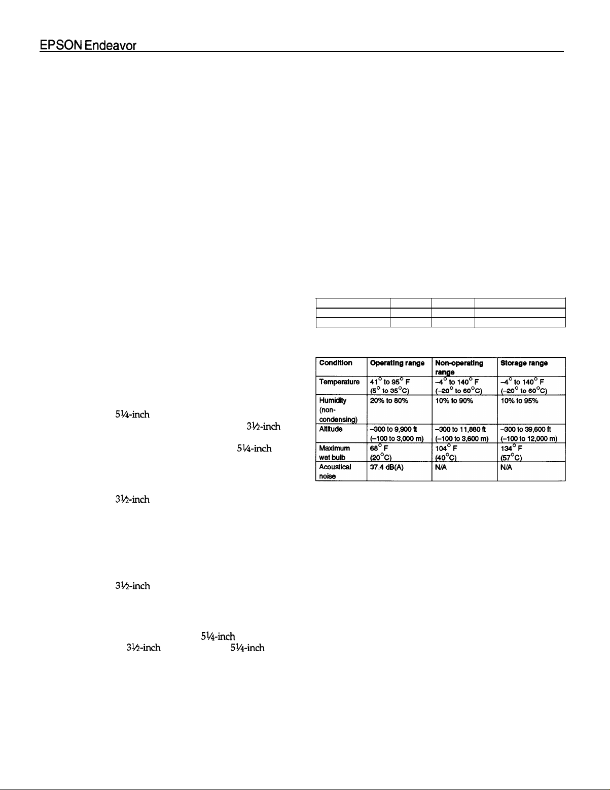
Environmental Requirements
Physical Characteristics
Width
Depth
Height 4.8 inches (120 mm)
weight
14.8 inches (370 mm)
16.5 inches (412 mm)
16.7 lb (7.6 kg), without keyboard
Your system may also be configured to
support SCSI devices, fax/modems, or
multimedia packages.
EPSON Endeavor WG-2
7/27/93
Page 3
EPSON Endeavor WG
Extended VGA Modes
NI = Non-interlaced
I = Interlaced
Wingine Modes
Major Subassemblies
main system
board
J15-J9 option board
riser,card
\
processor diskette
\
speaker
drive
power supply
,vertical
drive bay
switch
horizontal
drive bays
= Non-interlaced
NI
I
= Interlaced
5/3/93
EPSON Endeavor WG3
Page 4

EPSON Endeavor WG
Main System Board Diagram
EPSON Endeavor WG-4
5/3/93
Page 5

EPSON Endeavor WG
Connector Pin Assignments
Parallel Port Connector (CN5)
pin 13
pin 25
Parallel Port Connector Pin Assignments
*Active low logic
Serial Port Connectors (CN4 and CN8)
Serial Port Connector Pin Assignments
pin 1
pin 14
VGA Port Connector (CN2)
pin 5
pin 10
pin 15
VGA Port Connector Pin Assignments
VGA Feature Connector (CN17)
VGA Feature Connector Pin Assignments
Pin Signal
BLANK
10
HSYNC 20
11
VSYNC
12
13
Ground
14
Ground
Ground
15
18
Ground
w
*Active low logic
17 EN DATA*
18
ENSYNC*
pin 1
pin 8
pin 11
Signal
Pin
EN PCLK*
19
Not connected
Ground
21
Ground
22
Ground
23
Ground
24
Not connected
25
Not connected
26
15 INotused
Keyboard Connector (CN10) and
Mouse Connector (CN9)
Caution
I
-1
Although the keyboard and mouse connectors are
physically identical, they cannot be used interchangeably.
Keyboard and Mouse Connector Pin Assignments
tin Signal
1
Data
2
Reserved
Ground
3
Pin
Signal
4
+5 VDC (fused)
5
Clock
6
Reserved
DMA Assignments
Level
DMA0
DMA1
DMA2
DMA3
DMA4
DMA5
DMA8
DMA7
5/3/93
Assigned device
Spare (&bit)
Spare (&bit)
Floppy disk drive controller (&bit)
Spare (8-bit)
Cascade
Spare (16-bit)
Spare (16-bit)
Spate (16-bit)
to DMA controller 1
EPSON Endeavor WG-5
Page 6

EPSON Endeavor WG
Hardware Interrupts
IRQ no. Function
IRQ0
IRQ1
IRQ3
IRQ4
IRQ5
IRQ6
IRQ7
IRQ8
IRQ9
IRQ10
IRQ11
IRQ12
IRQ13
IRQ14
IRQ15
Timer output
Keyboard
Serial port 2
Serial port 1
Available (parallel port 2)
Floppy disk drive controller
Parallel port 1
Real-time clock
Available
Available
Available
PS/2 compatible mouse or optional pointing device
Math coprocessor
Hard disk drive controller
Available
* Recommended addresses for installing devices
System I/O Address Map
Jumper Settings
See the illustration on page 3 for the location of the jumpers
on the main system board.
CPU Speed Jumper Settings
A
153’ 154’
jB
IA
IA
J8
B
A
B B
CPU speed
SX/33, DX2/66 (33 MHz)
DX2/50 (25 MHz)
* Factory setting according to processor external speed clock; do not change
these jumpers unless you replace a DX2/50 chip with a DX2/66 chip.
IJl*
jA
]B IB IA
152’
IA
CPU Type lumper Settings
CPU type*
486SX/33
ODP486-33 or 487SX/33
ODP486DX50/66
* Factory-set according to system type. You need to change jumpers
J5-J8 only if you have the 4SX/33 system and you remove the original
microprocessor chip and install a new one, or if you install a future
OverDrive processor in the 4DX2/50 or 4DX2/66.
J5 J6 J7
B B B
A A A
A
Other Jumper Settings
Jumper
number
J9**
J10
J11
J12**
Jumper
setting
A*
B
A’
B
A’
B
A
Function
Enables the built-in mouse connector
Disables the built-in mouse connector
Enables the built-in VGA display adapter
Disables the built-in VGA display adapter
A color monitor is installed
A monochrome monitor is installed
Enables a mouse or other pointing device
EPSON Endeavor WG-6
Disables a mouse or other pointing device
Cl
* Factory setting
“To use a mouse connected to a port on an option card, set J9 to B and
J12 to A. lf you connect another type of pointing device (such as a joy
stick) to the option card port, set both jumpers to A.
5/3/93
Page 7

EPSON Endeavor WG
Processor Chips
If you have the 4SX/33 system, you can install an Intel
OverDrive processor (ODP486-33) or a 487SX/33
microprocessor (with built-in math coprocessor) on the main
system board. Installing an OverDrive processor effectively
doubles the internal clock speed of the computer’s
microprocessor; future OverDrive processors may be
available for the 4DX2/50 and 4DX2/66 systems.
SIMM Installation
There are two SIMM sockets on the main system board. To
increase the amount of memory in the computer up to
128MB, you can install 36-bit, fast-page mode SIMMs that
operate at an access speed of 70 ns or faster, with a capacity
of 1MB, 4MB, 16MB, or 64MB.
The following table shows the possible SIMM configurations;
do not install memory in any other configuration. Make sure
that both SIMMs operate at the same speed. There is 4MB of
memory soldered onto the main system board.
SIMM Configurations
(SIMM1
1
SIMM 2
1
Total memory
Hard Disk Drive Types
The table below lists types of hard disk drives you can use in
the computer. Check this table and your hard disk manual to
find the correct type number(s) for the hard disk drive(s)
installed in the computer. You need to enter the type
number(s) when you set the hard disk drive configuration in
the SETUP program.
Hard Disk Drive Types
* Standard soldered memory
**When SIMM is available
t
This memory configuration disables the 4MB of soldered memory
* Actual size when formatted may be slightly different than the size listed
on the drive label.
t
Hard disk drive supported in translate mode
*
Epson drives
5/3/93
EPSON Endeavor WG-7
Page 8

EPSON Endeavor WG
If the computer has an Epson 120MB or 240MB hard disk
drive, select the appropriate type number from the table
below.
Epson Hard Disk Drive Types
Type number
39
34
Epson hard disk drive
120MB
240MB
Installation/Support Tips
Power
The computer has an input voltage selection switch on the
back panel to select between 115V, for USA and Canadian
use, and 230V, for use in other countries.
Mouse and Keyboard
When connecting the mouse and keyboard to the computer,
be careful to plug them into the proper ports. Although the
ports are physically identical, they are not interchangeable,
and you can damage the main system board if you plug the
connectors into the wrong ports.
Installing Diskette Drives
Make sure that the drive type has been correctly selected in
the SETUP program.
Installing Hard Disk Drives
Cl It is recommended that a 16-bit, AT-type hard disk
controller be used if
use the embedded IDE interface. If you install a non-IDE
hard disk drive and controller card, you need to use the
SETUP program to disable the built-in IDE hard disk drive
interface.
See the hard disk drive type tables on page 7 and use the
SETUP program to enter the correct type number(s) for
the hard disk drive(s) installed in the computer. (Also be
sure to use the SETUP program to set the hard disk drive
configuration if you install or remove a hard disk drive.)
You can select a type number that matches the parameters
for the drive or a type number with parameters having
lesser values, as long as they do not exceed the maximum
capacity (in MB) of the drive. If there is no match for the
drive, you
or 2 option and enter the drive’s exact parameters.
can
press
you
are installing a drive that cannot
Enter
and then F2 at the Hard disk 1
Q
If you are using a copy-protected program that does not
require a key disk but requires a special procedure to
install it on a hard disk, set the speed to low while you
install the program. Then set the speed to high while you
load and run the program. If this does not work, try
installing and loading the program at low speed and then
change to high speed to run it.
0
You can change the processor speed using the SETUP
program, the ESPEED program, or keyboard commands.
See the User’s Guide and
Setup Guide
for more information.
Password
Make sure that you do not forget the password you set. If you
do, you must disable it by setting jumper J13 on the main
system board to position A.
Information Reference List
Engineering Change Notices
None.
Technical Information Bulletins
None.
Product Support Bulletins
None.
Related Documentation
TM-ENDVRWG
PL-ENDVRWG
SPKENDVRWG
400196000 EPSON Endeavor WG Setup Guide
400195900
400193100
EPSON Endeavor WG Service Manual
EPSON Endeavor WG Parts Price List
EPSON Endeavor WG Self Paced Kit
EPSON Endeavor WG User’s Guide
EPSON VGA Utilities Guide for Wingine
based products
Software Problems
Cl
If you are using a copy-protected program that can run
only on a diskette or that requires a key disk, try to load
the program at high speed. If you can’t load the program
at high speed, set the processor speed to automatic.
EPSON Endeavor WG-8
5/3/93
 Loading...