

Page 1
EPSON Endeavor P60
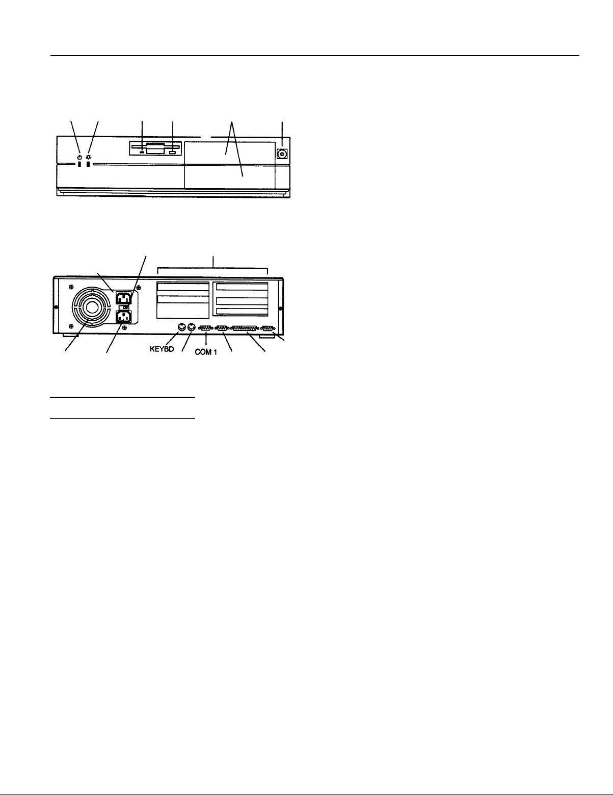
hard disk
drive
access light light
AC output
socket
\
power
supply fan
AC input
socket
diskette
power drive
access light button
voltage
selector
switch
/c
diskette
release
expansion
card slots
MOUSE
Computer Specifications
CPU and Memory
CPU
System speed
System memory
Intel Pentium 60 MHZ microprocessor;
backward compatible with 8086, 80286,
I386,
and i486 CPUs; supports read and
write burst mode bus cycles; built-in 16KB
write-back cache; integrated math
coprocessor
High and low speeds available; high speed
is 60 MHz and low speed is simulated
8 MHz for compatibility; speed selection
through Setup program or keyboard
commands
8MB standard memory on two 4MB
SIMMs; expandable to 128MB using 1MB,
2MB, 4MB, 8MB, 16MB, and 32MB SIMMs
(when readily available); SIMMs must be
32-bit or 36-bit, 72-pin, 70ns or faster,
tin-plated, fast-page mode, parity/no
parity type
blank filer
panels
COM2 LPT
power
button
\
VGA
Cache memory
ROM
Video RAM
Shadow RAM
Clock/
calendar
Controllers
Video
Diskette
Hard disk
Built-in 16KB of internal write-back cache
in the Pentium microprocessor; 256KB of
secondary, direct-mapped, write-through
cache on eight 32KB x 8, 15ns SRAMs on
the main system board; tag and control
logic on the 82434LX PCMC core chip
128KB system and video BIOS located on
a flash EEPROM device; contains Setup
program code, power-on self test code,
update recovery code, and the PCI board
auto-configuration utility; upgradable and
write-protectable
1MB of standard video RAM providing
video resolutions up to 1024 x 768 in
256 colors; expandable to 2MB by
installing eight 256KB X 4, 60ns ZIP
VRAMs on the main system board to
provide resolutions up to 1280 X 1024 in
256 colors
Supports shadowing of system and video
BIOS ROM, and ROM located on
expansion board adapters, into RAM
Real-time clock, calendar, and 128-byte
CMOS RAM (114 bytes for general
purpose non-volatile CMOS RAM and
14 bytes for clock and control registers)
on socketed DS12887 device; integrated
battery and oscillator; CMOS RAM
clearable and resettable using the Setup
program or by setting a main system
board jumper
ATI 68800AX Mach32 local bus PCI
graphics accelerator; compatible with
MDA, CGA, Hercules Graphics, EGA, and
VGA video standards; supports normal
and enhanced video modes; supports
interlaced and non-interlaced monitors
SMC FDC37C665 super I/O controller
with interface on the main system board
controls up to two diskette drives or one
diskette drive and one tape drive; 16-byte
data FIFO (first-in-first-out) with 2.88MB
diskette drive support
SMC FDC37C665 super I/O controller
with interface on the main system board
controls up to two IDE hard disk drives;
BIOS provides hard disk auto-sensing
function
3/94
EPSON Endeavor P60 - 1
Page 2
EPSON Endeavor P60
Parallel port
Serial ports
Interfaces
Video
Parallel
serial
Keyboard
Mouse
Expansion slots
Mass Storage
SMC FDC37C665 super I/O controller
provides multiple modes: standard (IBM
and Centronics compatible), enhanced
(EPP with bidirectional functions and
BIOS/driver support), and high speed
(ECP compatible)
SMC FDC37C665 super I/O controller
supports two RS-232C compatible serial
ports
SVGA PCI local bus interface with
standard, 15-pin analog connector; VESA
compliant 8514/A feature connector on
main system board for auxiliary video
subsystem installed in an expansion slot
Multimode, bidirectional parallel port
with 25-pin, D-shell connector
Two RS-232C compatible, programmable,
asynchronous serial ports with 9-pin,
D-shell connectors
PS/2 compatible keyboard port with
6-pin, mini DIN connector
PS/2 compatible mouse port with 6-pin,
mini DIN connector
Five expansion slots on expansion board
riser card: one full-length, 16-bit ISA slot;
two half-length, 16-bit ISA slots; one
full-length PCI slot, and one half-length
PCI slot
Internal
bays: one 3.5-inch, one-inch high
bay (for the standard diskette drive) and
one 3.5-inch, 1.6-inch high bay for an
optional internal drive in the drive carrier
Physical Characteristics
Dimension Specification
Width
Depth
Height
Weight
17.2 inches (43.7 cm)
16.2 inches (41.1 cm)
4.3 inches (11.0 cm)
20 b
Power Supply
Type
Input ranges
AC input
current
power
AC
outlet
Cables
145 Watt, switchable voltage; maximum
power dissipation: 120 Watts
90 to 135 VAC and 180 to 265 VAC;
50/60
Hz
5.0
3.0
at 90 to 135 VAC;
Amps
at 180 to 265 VAC
Amps
2.0 Amps maximum for 100
1 Amp maximum for 200 to
Two to main system board; four to mass
storage devices
DC output
Power consumption
DC voltage Current Watts (total: 30.67)
+5V
-5V
+12 V 0.044 Amp (10%)
-12V
3.3 v 0 Amp (5%)
6.0 Amps (5%)
0.016 Amp (5%)
0.011 Amp (10%)
(9.1 kg) without drives or keyboard
to 120 VAC;
240 VAC
30.0 w
0.008 w
0.528 W
0.132 W
0W
I
Externally accessible bays: Two 5.25-inch
half-height bays (can be used as one
5.25-inch, full-height bay)
Keyboard
Detachable, two-position height; 101 or
102 sculpted keys; country-dependent
main typewriter keyboard; numeric/
cursor control keypad; four-key cursor
control keypad; 12 function keys
Setup Program
Stored in ROM; accessible by pressing
during boot
EPSON Endeavor P60 - 2
F1
Expansion board power limits
To avoid damage to the system board or power supply, do
not exceed a total of 145 Watts power draw.
Environmental Requirements
3/94
Page 3
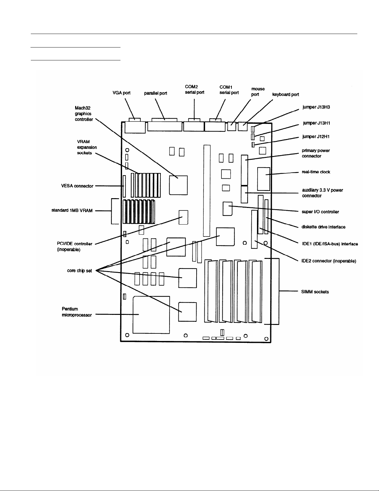
Main System Board Map
EPSON Endeavor P60
3/94
EPSON Endeavor P60 - 3
Page 4

EPSON Endeavor P60
System board components and connectors
SIMM Installation
Your computer comes with 8MB of memory on two 4MB
SIMMs. You can increase the memory up to 128MB using
1MB, 2MB, 4MB, 8MB, 16MB, and 32MB SIMMs (when
readily available).
The SIMM sockets are organized in two banks (Bank 0 and
Bank 1) consisting of two sockets each. You must install the
same type of SIMM in a bank.
The SIMMs you install must be 32-bit or 36-bit, 72-pin, 70ns,
tin-plated, fast-page mode, parity/no parity DRAM. The
table below lists the 16MB and 32MB SIMMs that are
approved for use in your system. You can install these
SIMMs or their equivalents.
Manufacturer
Samsung
Samsung
Hitachi
Description
16MB; with
16MB; no parity
32MB; with parity
parity
The table below lists possible combinations of SIMMs you
can install; do not use any configuration other than one of
those listed in the table.
SIMM configurations
Part number
KM41C00BJ-7
KMM5324000BG-7
HM5117400J7
Jumper Settings
Main system board jumper settings
EPSON Endeavor P60 - 4
3/94
Page 5

EPSON Endeavor P60
Video Memory, Modes, and Monitors
This system comes with 1MB of VRAM soldered on the main
system board. You can increase the video memory to 2MB by
installing eight VRAM ZIP chips (256KB x 4, 60ns, fast-page
mode). You must fill all eight sockets.
The table below lists the video modes supported by the
system.
Resolutions and colors
Color
Resolution bpp(1) rate)
640x480
640x480
640x480
640x480
640x480
800x600
800x600
800x600
depth
8 60
8(2)
8(3)
16 60
16
8
16
16 56
Vertical Hz
(refresh Horizontal
72
72
72
76
95 (4)
Hz
31.5
37.0 Y
44.6 Y
31.5 Y
37.0 Y
52.4 Y
33.8 Y
35.2 Y Y
1MB
support support
Y
2MB
Y
Y
Y
Y
Y
Y
Y
The table below lists the monitors that are directly supported
by the Mach32 accelerator.
Check the monitor documentation to see if its characteristics
match one of the listed types. If so, select that type in the
Mach32 installation program.
For EPSON monitors, see the second table for information on
the monitor type to select.
If the monitor does not match any of these types, set up a
custom monitor.
Mach32 monitor list
800x600
1024x768
1024x768
1024x768
1024x768
1024x768
1024x768
1024x768
1024x768
(1) bpp=bits per pixel: 4 bpp=16 colors, 8 bpp=256 colors,
16 bpp=65,000 colors, 24 bpp=16.7 million colors
(2) 32 MHz setting
(3) 40 MHz setting
(4) Interlaced
24 72
8 87 (4)
8 60
8 66
8 70 56.1
8
8 76
16 87 (4)
16 60
72 57.9
48.0
35.5 Y
48.4 Y
53.9 Y Y
61.4
35.5
48.4
N
Y
Y
Y Y
N
N
EPSON monitor types
Y
Y
Y
Y
Y
Y
Y
Hard Disk Drive Types
This system comes with a hard disk auto-sensing feature.
Some drives do not support the auto-sensing feature. If the
system does not correctly define your hard disk drive, you
can define up to two drive types in SETUP.
3/94
EPSON Endeavor P60 - 5
Page 6

EPSON Endeavor P60
Drive Option Information
Hard disk drive options for l-inch IDE drives
System Memory Map
System l/O Addresses
l
Select 1 or none for the precomp value. If neither of these options are
available, select the maximum available precomp value.
IDE hard disk drive jumper settings
Model number Single drive
Conner CP30254
Conner CR30344
Conner CFS420A
Conner CFA540A
Quantum LPS240AT
Western Digital AC2250
Western Digital AC2340
l
CS (cable selection) can be jumpered for any configuration. When Cs is
used, the drive is a master if pin 28 is grounded and a slave if pin 28 is not
grounded.
C/D jumpered C/D jumpered
C/D jumpered C/D jumpered
C/D jumpered C/D jumpered
C/D jumpered C/D jumpered
DS jumpered* SP and DS No jumpers l
No jumpers
No jumpers
Master drive Slave drive
No jumpers
No jumpers
No jumpers
No jumpers
jumpered*
MA jumpered SL jumpered
MA jumpered SL jumpered
Diskette drive options
EPSON Endeavor P60 - 6
3/94
Page 7

EPSON Endeavor P60
System I/O addresses (continued)
Address range
(hexadecimal) Description
C000-C0FF
C200-C2FF 823781B configuration registers
C300-C3FF
82434LX configuration registers
Onboard ATI configuration registers
System Board Interrupts
Interrupt
request (IRQ)
NMI
0
1
2
3
4
5
6
7
8
9
10
11
12
13
14
15
System resource
Panty error
Reserved, interval timer
Resewed, keyboard buffer full
Reserved, cascade interrupt from
Serial port 2
serial port 1
Parallel port 2
Diskette
Parallel port 1
Real-time dock
User-available
User-available
I
User-available
I Onboard mouse port if enabled; otherwise user-available
Reserved, math coprocessor
IDE if enabled; otherwise user-available
User-available
slave
Serial port connector pin assignments (J13E1, J13F1)
Primary power connector pin assignments (J11H1)
PIC
~~
DMA Channels
Connector Pin Assignments
Parallel port connector pin assignments (J13C1)
3/94
EPSON Endeavor P60 - 7
Page 8

EPSON Endeavor P60
AT IDE hard disk drive connector pin assignments (J8J2)
1
PinI Signal name
1
3
5
7
9
11
13
15
1
17
19
21
23
25
27 IOCHRDY
29
31
33 Addr 1
35
37
39
Reset IDE
Host Data
Host Data
Host Data
Host Data
Host
Host
Host
1
Host Data 0
Ground
DRQ3
l/O Write-
l/O Read-
DACK3IRQ14
Addr 0
I Chip Select 0-
1
Activity
7
6
5
4 10
Data
3 12 Host
Data
2
Data
1
I
Pin
2
4 Host Data
6
8
14 Host
16 Host
1
16
20 Key
22
24
26
28 BALE
30
32
34
36
38
40 Ground
I
Signal name
Ground
Host Data
Host Data
Host Data
Data
Data
Data
1
Host Data 15
Ground
Ground
Ground
Ground
IOCS16Ground
Addr 2
Chip Select 1-
8
9
10
11
12
13
14
Speaker connector pin assignments (J1F1)
ISA expansion board connector pin assignments (continued)
1
I
Auxiliary 12 V front fan connector pin assignments (J3A1)
Pin
1
2
3
Signal name
Ground
+12V (fused)
Ground
ISA expansion hard connector pin assignments
PCI expansion board connector pin assignments
EPSON Endeavor P60 - 8
3/94
Page 9

EPSON Endeavor P60
PCI expansion board connector pin assignments (continued)
VESA feature connector pin assignments (J10A1) (continued)
Mouse and keyboard connector pin assignments (J13G1 and J13H5)
Error Messages
Beep codes
Reset connector pin assignments (J1F2)
Pin
1
2
Power LED connector pin assignments (J1F3)
Hard disk drive LED connector pin assignments (J1G1)
Pin
1
2
3
4
Signal name
RESET
Ground
Signal name
PULL UP 330
HD ACTlVEKey
PULL UP 330
Number
of beeps Error message Description
1
2
3
4
5
6
7
8
9
10
11
Refresh Failure The memory refresh circuitry on the main
Parity E nor Parity error In the first 64KB of memory
Base 64KB Memory failure in the first 64KB of memory
Memory Failure
Timer Not
Operational or Timer 1 on the main system board is not
Processor Error The CPU generated an error
8042 - Gate
A20 Failure
Processor The CPU generated an exception interrupt
Exception
Interrupt Error
Display Memory The system video adapter is either missing
Read/Write Error
ROM Checksum The ROM checksum value does not match
Error the value encoded in the BIOS
CMOS Shutdown
Register
Read/Write Error
Cache The external cache is faulty
Error/External
Cache Bad
system board is faulty
Memory failure in the first 64KB of memory
functioning
The keyboard controller may be bad; the
BIOS cannot switch to protected mode
or its memory is faulty: not a fatal error
The shutdown register for CMOS RAM failed
Turbo LED connector pin assignments (J1H1)
Pin
1
2
Signal name
PULL UP 330
LED TURBO
Video monitor port connector pin assignments (J13A1)
VESA feature connector pin assignments (J10A1)
Error messages
3/94
EPSON Endeavor P60 - 9
Page 10

EPSON Endeavor P60
Error messages (continued)
Tested Operating Environments
Although the system will run most software applications,
the following operating environments have been tested for
compatibility with this system.
Microsoft MS-DOS
Novell DR DOS 6.0
Novell NetWare 2.2, 3.12, and 4.01
Novell NetWare Lite 1.1
IBM OS/22.1
SCO UNIX release 3.2, version 4.2
SCO Open Desktop 3.0
Microsoft Windows 3.0 and 3.1
Microsoft Windows for WorkGroups 3.11
Microsoft Windows NT 3.1
NextStep version 3.2
LAN Manager
This system has also received Novell’s ‘Yes, NetWare tested
and approved” certification as a workstation and file server.
As new environments become available, these also will be
tested and certified.
Installation/Support Tips
ISA NM messages
ISA NMI message
Memory Parity Eror at
I/O Card Parity Error at
DMA Bus Time-out
Description
Memory failed; if the memory location can be
determined, it is displayed as xxxxxx; if not, the
message is Memory Parity Error ????
An expansion card failed; if the address can be
determined, it is displayed as xxxxx: if not, the
message is l/O card Parity Error ????
A device has driven the DMA bus signal for more
1
than 7.8 microseconds
System Power Requirements
If the power cord supplied with the system is not compatible
with the electrical outlet, obtain a cord that meets these
criteria :
0
The cord must be rated for at least 125% of the current
rating of the AC voltage system.
0
The cord must be less than 4.5 meters (14.8 feet) long.
0
The connector that plugs into the electrical outlet must be
an appropriately designed male grounding-type
connector.
0
The connector that plugs into the computer must be an
IEC type CEE-22 female connector.
Do not use or attempt to modify the supplied AC power cord
if it is not the type required for use in your region.
To avoid permanent damage to the computer, be sure the
voltage selector switch is set to the correct input line voltage
before you turn on the power. Verify that the voltage selector
switch is set to the correct setting. The 115 VAC setting is
appropriate for line source voltages between 100 and 120
VAC. If the line source voltage in your location is between
200 and 240 VAC, make sure you set the switch to 230 VAC.
To avoid damage to the system board or power supply, do
not exceed a total of 145 Watts power draw.
EPSON Endeavor P60 - 10
3/94
Page 11

Keyboard and Monitor
Even if you intend to use this system as a network file server,
you need to connect a monitor and a keyboard to complete
the installation. You may remove them once the installation
is complete.
Mouse and Keyboard
When connecting the mouse and keyboard, be careful to plug
them into the proper ports. Although they are physically
identical, they are not interchangeable, and damage may
occur to the ports or the main system board.
Expansion Boards
If you are installing a video expansion board containing a
secondary controller, it must be an MDA or CGA card with
no BIOS. You must use the computer’s built-in VGA
controller as the primary controller.
You must install an expansion slot cover on any vacant
expansion slots to maintain the electromagnetic emissions
and cooling characteristics of the system.
IBM 16/4 Token Ring Network Adapters
EPSON Endeavor P60
Do not install Type 1 of the IBM 16/4 Token Ring network
adapter in the computer because the adapter will not
correctly initialize. You can install the Type 3 adapter if you
disable the appropriate shadow memory area and assign the
correct IRQ 9 setting (if you use IRQ 2). For example, if you
set the adapter’s ROM address to DC000h, the RAM address
to D8000h, the RAM size to 16KB, and the IRQ setting to
IRQ 2, you must make the following changes to these
Advanced CMOS Setup options:
Disable Shadow Memory Base option:
Disable Shadow Memory Size option:
ISA IRQ 9 option:
Set to D8000h
Set to 32KB
set to used
Information Reference List
Engineering Change Notices
None.
Technical Information Bulletins
None.
Product Support Bulletins
None.
Related Documentation
TM-ENDVRP60
PL-ENDVRP60
400304600
EPSON Endeavor P60 Service Manual
EPSON Endeavor P60 Parts Price List
EPSON Endeavor P60 User’s Guide
3/94
EPSON Endeavor P60 - 11
 Loading...