

Page 1
EPSON Endeavor 468C
Page 2

FCC COMPLIANCE STATEMENT
FOR AMERICAN USERS
This equipment has been tested and found to comply with the limits for a class B digital
device, pursuant to Part 15 of the FCC Rules. These limits are designed to provide
reasonable protection against harmful interference in a residential installation. This
equipment generates, uses, and can radiate radio frequency energy and, if not installed
and used in accordance with the instructions, may cause harmful interference to radio and
television reception. However, there is no guarantee that interference will not occur in a
particular installation. If this equipment does cause interference to radio and television
reception, which can be determined by
turning
the equipment off and on, the user is
encouraged to try to correct the interference by one or more of the following measures:
q
Reorient or relocate the receiving antenna
q
Increase the separation between the equipment and receiver
q
Connect the equipment into an outlet on a circuit different from that to which the
receiver is connected
q
Consult an experienced radio/TV technician for help.
WARNING
The connection of a non-shielded equipment interface cable to this equipment will
invalidate the FCC Certification of this device and may cause interference levels that
exceed the limits established by the FCC for this equipment. It is the responsibility of the
user to obtain and use a shielded equipment interface cable with this device. If this
equipment has more than one interface connector, do not leave cables connected to unused
interfaces.
Changes or modifications not expressly approved by the manufacturer could void the
user’s authority to operate the equipment,
FOR CANADIAN USERS
This digital apparatus does not exceed the Class B limits for radio noise emissions from
digital apparatus as set out in the radio interference regulations of the Canadian
Department of Communications.
Le présent appareil numérique n'émet pas de bruits radioélectriques dépassant les limites
applicables aux appareils numériques de Classe
B
prescrites dans le réglement sur le
brouillage radioélectrique édicté par le Ministére des Communications du Canada.
Page 3

®
EPSON
User’s Guide
This manual is printed on recycled paper and is 100% recyclable.
Page 4

IMPORTANT NOTICE
DISCLAIMER OF WARRANTY
Epson America makes no representations or warranties, either express or implied, by or
with respect to anything in this manual, and shall not be liable for any implied warranties
of merchantability and fitness for a particular purpose or for any indirect, special, or
consequential damages. Some states do not allow the exclusion of incidental or
consequential damages, so this exclusion may not apply to you.
COPYRIGHT NOTICE
All rights reserved. No part of this publication may be reproduced, stored in a retrieval
system, or transmitted, in any form or by any means, electronic, mechanical,
photocopying, recording, or otherwise, without the prior written permission of Epson
America, Inc. No patent liability is assumed with respect to the use of information
contained herein. Nor is any liability assumed for damages resulting from the use of the
information contained herein. Further, this publication and features described herein are
subject to change without notice.
TRADEMARKS
Epson is a registered trademark of Seiko Epson Corporation.
General notice: Other product names used herein are for identification purposes only and
may be trademarks of their respective owners. Epson disclaims any and all rights in those
marks.
Copyright © 1993 by Epson America, Inc.
Torrance, California
ii
400230800
Page 5

Important Safety Instructions
Read all of these instructions and save them for later reference.
1.
Follow all warnings and instructions marked on the computer.
2.
Unplug the computer from the wall outlet before cleaning. Use a
3.
damp cloth for cleaning; do not use liquid or aerosol cleaners.
Do not spill liquid of any kind on the computer,
4.
Do not place the computer on an unstable cart, stand, or table.
5.
Slots and openings in the cabinet and the back or bottom are
6.
provided for ventilation; do not block or cover these openings.
Do not place the computer near or over a radiator or heat
register.
Operate the computer using the type of power source indicated
7.
on its label.
If you plan to operate the computer in Germany, observe the
8.
following safety precaution:
To provide adequate short-circuit protection and over-current
protection for this computer, the building installation must be
protected by a 16 Amp circuit breaker.
Beim AnschluB des Computers an die Netzversorgung muB
sichergestellt werden, daB die Gebäudeinstallation mit einem
16 A Überstromschutzschalter abgesichert ist.
Connect all equipment to properly grounded (earthed) power
9.
outlets. If you are unable to insert the plug into an outlet,
contact your electrician to replace your outlet. Avoid using
outlets on the same circuit as photocopiers or air control
systems that regularly switch on and off.
iii
Page 6

10. Do not allow the computer’s power cord to become damaged or
frayed.
11. If you use an extension cord with the computer, make sure the
total of the ampere ratings of the devices plugged into the
extension cord does not exceed the ampere rating for the
extension cord. Also, make sure the total of all products
plugged into the wall outlet does not exceed 15 amperes.
12. Do not insert objects of any kind into this product through the
cabinet slots.
13. Except as specifically explained in this User’s Guide, do not
attempt to service the computer yourself. Refer all servicing to
qualified service personnel.
14. Unplug the computer from the wall outlet and refer servicing to
qualified service personnel under the following conditions:
A.
When the power cord or plug is damaged.
B.
If liquid has entered the computer.
C.
If the computer does not operate normally when the
operating instructions are followed. Adjust only those
controls that are covered by the operating instructions.
Improper adjustment of other controls may result in
damage and often requires extensive work by a qualified
technician to restore the computer to normal operation.
iv
D.
If the computer has been dropped or the cabinet has been
damaged.
E.
If the computer exhibits a distinct change in performance.
Page 7

Instructions Importantes de Sécurité
1.
Lire complètement les instructions qui suivent et les conserver
pour references futures.
2.
Bien suivre tous les avertissements et les instructions indiqués sur
l’ordinateur.
3.
Débrancher l’ordinateur de toute sortie murale avant le nettoyage.
Utiliser un chiffon humide; ne jamais utiliser un nettoyeur
liquide ou une bonbonne aerosol.
4.
Ne jamais renverser un liquide d’aucune sorte sur l’ordinateur.
5.
Ne pas placer l’ordinateur sur un chariot, un support, ou une table
instable.
6.
Les évents dans les meubles,á l’arrière et en dessous sont conçus
pour l’aération; on ne doit jamais les bloquer. Ne pas placer
l’ordinateur prés d‘une source de chaleur directe.
7.
Le fonctionnement de l’ordinateur doit s’effectuer conformement
au type de source d’alimentation indiquée sur l’étiquette.
8.
Lorsqu’on desire utiliser l’ordinateur en Allemagne, on doit
observer les normes securitaires qui suivent:
Afin d’assurer une protection adequate à l’ordinateur contre les
court-circuits et le survoltage, l’installation de l’edifice doit
comprendre un disjoncteur de 16 amp.
9.
On doit brancher tout l’équipement dans une sortie reliée à la
masse. Lorsqu’il est impossible d’insérer la fiche dans la prise, on
doit retenir les services d’un électricien ou remplacer la prise. Ne
jamais utiliser une prise sur le meme circuit qu’un appareil à
photocopie ou un système de contrôle d‘aération avec
commutation marche-arret.
v
Page 8

10.
S’assurer que le cordon d’alimentation de l’ordinateur n’est pas
effrite.
11. Dans le cas où on utilise un cordon de rallonge avec l’ordinateur,
on doit s’assurer que la valeur totale d’ampères branches dans le
cordon n’excède en aucun temps les ampères du cordon de
rallonge. La quantité totale des appareils branches dans la prise
murale ne doit jamais excéder 15 amperes.
12. Ne jamais insérer un objet de quelque sorte que ce soit dans les
cavités de cet appareil.
13. Sauf tel que spécifié dans la notice d’utilisation, on ne doit jamais
tenter d’effectuer une reparation de l’ordinateur. On doit référer
le service de cet appareil à un technicien qualifié.
14. Débrancher l’ordinateur de la prise murale et confier le service au
personnel de service qualifié selon les conditions qui suivent:
A.
Lorsque le cordon d’alimentation ou la prise sont
endommagés.
B.
Lorsquun liquide s’est infiltré dans l’ordinateur.
C.
Lorsque l’ordinateur refuse de fonctionner normalement
même en suivant les instructions. N’ajuster que les
commandes qui sont énumérées dans les instructions de
fonctionnement. Tout ajustement inadéquat de tout autre
contrôle peut provoquer un dommage et souvent nécessiter
des réparations élaborées par un technicien qualifié afin de
remettre l’appareil en service.
vi
D.
Lorsqu’on a échappe l’ordinateur ou que l’on a endommagé le
boîtier.
E.
Lorsque l’ordinateur démontre un changement noté au niveau
de sa performance.
Page 9

Contents
VGA Utilities
Optional Equipment
System Memory
Cache Memory
Video Memory
OverDrive Processor
Math Coprocessor
Drives
How to Use This Manual
...................
...............
..............
...............
...............
............
.............
....................
............
Conventions Used in This Manual
Where to Get Help
Chapter 1
1 Choosing a Location
2 Connecting a Monitor
................
Setting Up Your System
..........
........
3 Connecting a Printer or Other Device
Using the Parallel Port
Using the Serial Ports
4 Connecting the Keyboard
5 Connecting the Mouse
6 Connecting the Power Cord
7 Turning On the Computer
Turning Off the Computer
....... .............
.......
......
........
.....
...... .............
.......
......
......
......
......
......
......
......
......
......
....
.............
......
......
.............
.............
2
2
2
3
3
3
3
3
4
5
6
l-2
l-2
l-5
l-5
............. l-7
.............
.............
.............
l-8
l-9
l-11
l-12
............. l-14
vii
Page 10

Chapter 2
Running the SETUP Program
Starting the SETUP Program
Entering SETUP Options
Selecting Options
Setting the Date and Time
Setting the Diskette Drive(s)
Setting the Hard Disk Drive(s)
Hard Disk Drive Types
Defining Your Own Drive Type
Setting the Primary Display Type
Setting the Processor Speed
Setting the Booting Sequence
Setting the Diskette Seek Parameter
Using the SETUP Screen Submenus
Setting the Shadow Options
Setting the Keyboard Options
Setting the Peripherals Options
Setting the Password Options
Entering a Password
Changing or Deleting a Password
....................
......................
.......................
.....................
....................
..................
....................
...............
.................
....................
...................
...............
...............
.................
................
...............
...................
.....................
..............
Setting the Keyboard Lock Option
Using the System Board Help Function
Loading Default SETUP Values
..................
Saving Your Settings and Exiting SETUP
Post-SETUP Procedures
......................
.............
.............
............
2-3
2-4
2-4
2-5
2-5
2-6
2-7
2-9
2-9
2-l 1
2-l 1
2-12
2-12
2-12
2-13
2-14
2-15
2-15
2-16
2-16
2-17
2-17
2-18
2-19
Chapter 3
Working Comfortably
Sitting at Your Computer
Using Your Computer
............
........
Varying Your Posture and Movements . .
Lighting the Room
.........
Positioning and Viewing the Monitor .
Using Disks and Disk Drives
Types of Diskette Drives
Write-protecting Diskettes
Vlll
........
........
.......
. . . .
. . . .
. . . .
. . . .
. . . .
. . . .
. . . .
. . . .
3-l3-l
3-2
3-33-3
3-33-3
3-43-4
3-53-5
3-5
3-73-7
Page 11

Inserting and Removing Diskettes
Using a Single Diskette Drive System
Formatting Diskettes
Making Backup Copies
Caring for Diskettes
Using a Hard Disk Drive
Special Keys on the Keyboard
.............
............
..............
...........
...........
Stopping a Command or Program
Resetting the Computer
Using a Password
Using the Hot Key Feature
...............
..................
..........
Changing or Deleting a Password
Changing the Processor Speed
...........
.........
.......
.........
.......
3-9
3-10
3-11
3-11
3-12
3-12
3-14
3-15
3-16
3-17
3-17
3-18
3-18
Chapter 4
How to Use This Chapter
Locating the Internal Components
Removing the Cover
Changing
Setting the Jumpers
Setting the DIP Switches
Memory Modules (SIMMs)
Inserting SIMMs
Removing SIMMs
Installing an Option Card
Using the VGA Feature Connector
Removing an Option Card
Installing and Removing Options
......................
........................
the
Jumper and DIP Switch Settings
......................
...................
.................
........................
.......................
......................
................
.....................
..............
Removing the Option Card Connector Board
Replacing the Option Card Connector Board
Installing a New Processor Chip
Replacing the Processor Chip
Increasing the Video Memory
Installing the Video Memory Chips
Replacing the Battery
Replacing the Cover
........................
.........................
Post-installation Procedures
..................
.................
...................
.............
....................
.........
..........
..........
4-2
4-3
4-4
4-6
4-8
4-9
4-10
4-l 1
4-13
4-14
4-17
4-19
4-20
4-21
4-21
4-23
4-25
4-25
4-27
4-31
4-32
ix
Page 12

Chapter 5
lnstalling and Removing Drives
How to Use This Chapter
Setting the Hard Disk Drive Jumpers
Where to Go Next
Installing a Hard Disk in the Vertical Bay
Removing the Mounting Frames
Installing the Hard Disk
Connecting the Cables
Removing a Hard Disk From the Vertical Bay
Installing a Drive in a Horizontal Bay
......................
...............
........................
.............
...............
....................
.....................
..........
...............
Attaching Mounting Frames to a Hard Disk
Installing the Drive
Connecting the Cables
Removing a Drive From a Horizontal Bay
.......................
.....................
.............
Connecting the Hard Disk Drive Ribbon Cable to
the System Board
Post-installation Procedures
Chapter 6
Identifying Your System
Error Messages
The Computer Won’t Start
The Computer Does Not Respond
Restoring the Power Supply
Password Problems
Accessing Your System
Keyboard Problems
Monitor Problems
Diskette Problems
Diskette Drive Problems
Hard Disk Problems
Installing the Drive
Preparing the Drive
Accessing Data on the Drive
Software Problems
..........................
.....................
Troubleshooting
.......................
............................
......................
.................
..................
..........................
.....................
..........................
...........................
..........................
.......................
.........................
.......................
.......................
..................
..........................
.........
5-3
5-4
5-4
5-5
5-5
5-7
5-l1
5-14
5-16
5-17
5-18
5-22
5-26
5-30
5-33
6-l
6-2
6-5
6-6
6-7
6-8
6-9
6-10
6-10
6-12
6-14
6-14
6-15
6-16
6-16
6-17
X
Page 13

Printer Problems
Option Card Problems
Mouse Problems
Memory Module Problems
External Cache Problems
Battery Problems
Appendix A Specifications
...........................
.......................
...........................
.....................
......................
...........................
6-18
6-20
6-20
6-21
6-22
6-22
CPU and Memory . . . .
Controllers . . . . . . .
Interfaces . . . . . . . .
Mass Storage . . . . . .
Input Devices . . . . .
Power Supply . . . . . .
Environmental Requirements
Power Source Requirements .
System Memory Map. . .
Glossary
index
.........
.........
.........
.........
.........
.........
.........
.........
.........
A-l
A-2
A-2
A-3
A-3
A-4
A-4
A-5
A-6
xi
Page 14

Ihtroduction
Your new Epson® computer is a fast, high-performance system
offering flexibility and expandability in a compact design.
Standard features include:
qq
486SX/25
microprocessor
qq
4MB of internal memory, expandable to 36MB
qq
System and video BIOS shadow RAM
qq
8KB of internal processor cache, with support for 64KB,
128KB, or 256KB external cache
qq
512KB of on-board video memory, expandable to 1MB
qq
Math coprocessor built into the microprocessor for the
33 MHz and 50 MHz systems
qq
Built-in VGA port
qq
Two built-in serial ports and one built-in parallel port
MHz, 486DX/33 MHz, or 486DX2/50 MHz
qq
Built-in IBM® PS/2™ compatible keyboard and mouse ports
qq
On-board VGA feature connector
qq
Four 16-bit (or 8-bit) ISA option slots
qq
Support for up to three internal mass storage devices
qq
Password security.
Using the built-in interfaces, you can connect your peripheral
devices directly to the computer so you don’t have to install
option cards. Use the option slots to enhance your system with
such functions as a modem card or additional interface ports.
Introduction 1
Page 15

With 512KB standard video memory, the built-in VGA adapter
supports resolutions of up to 800 x 600 (256 colors), and
640 x 480 (64K colors). Extend the video memory to 1MB to
support resolutions of 1280 x 1024 (16 colors), 1024 x 768
(256
colors), or 800 x 600 (64K colors).
If you install a high-resolution graphics adapter card or
full-motion, multi-media card, you can connect it to the
computer’s VGA feature connector. This allows you to use the
adapter’s special graphics features while accessing the standard
VGA signals provided by your main system board.
VGA Utilities
Your computer comes with special VGA drivers and utilities for
use with the integrated VGA interface. Use these utilities to take
advantage of extended VGA features such as high resolutions
and 132-column text mode when you run popular application
programs. Instructions for installing and using these drivers are
in a readme file called VGADRV.TXT on the Utilities 1 diskette.
If your system came configured with a hard disk drive, you
may also find this file by selecting the VGA Utils group icon in
Microsoft®Windows’“. See page 2-19 for more information.
Optional Equipment
You can easily upgrade your computer by installing additional
memory and a wide variety of options, as described below.
(Installation instructions are provided in Chapters 4 and 5.)
System Memory
By adding lMB, 4MB, or 16MB SIMMs (single inline memory
modules) to the main system board, you can expand the
computer’s memory up to 36MB.
2 Introduction
Page 16

Cache Memory
You can increase the cache memory on your main system board
to 256KB by having additional SRAM chips installed by an
Authorized Epson Servicer. Additional cache allows your
system to access frequently used data faster.
Video Memory
You can add video memory chips to your system board to
increase the video memory to 1MB and support higher video
resolutions, multimedia graphics adapter cards, or applications
that require higher memory.
OverDrive Processor
You can enhance your 25 MHz or 33 MHz system by replacing
your microprocessor chip with an Intel® OverDrive™ processor.
This processor doubles the internal clock speed so your system
runs much faster.
Math Coprocessor
If you have the 25 MHz system, you may want to install an
80487SX, 25 MHz coprocessor. This optional microprocessor
includes a built-in math coprocessor so your computer
performs mathematical functions faster.
Drives
Your system supports up to three mass storage devices,
including hard disk drives, diskette drives, a tape drive, or a
CD-ROM drive.
introduction 3
Page 17

How to Use This Manual
You don’t have to read everything in this book to use your
computer; see the following chapter summaries to find the
sections you need.
Chapter 1
provides steps for setting up your system and
connecting peripheral devices.
Chapter
2 describes how to run the SETUP program to define
your computer’s configuration. Do this the first time you use
your computer. If you change the configuration later, you will
need to run it again.
Chapter
3 covers general operating procedures, such as turning
the computer on and off, using disks and disk drives, entering a
password, and changing the processor speed.
Chapter
4 describes how to install optional equipment such as
option cards and memory modules.
Chapter
Chapter
Appendix A
At the end of this manual, you’ll find a
5 explains how to install and remove disk drives.
6 contains troubleshooting tips.
lists the specifications of your computer.
Glossary
and an Index.
4 Introduction
Page 18

Conventions Used in This Manual
This manual uses the following type conventions:
Introduction 5
Page 19

Where to Get Help
If you purchased your computer outside the United States,
please contact your dealer or the marketing location nearest you
for customer support and service. International marketing
locations are listed at the back of this manual.
If you purchased your computer in the United States, Epson
provides the following support services through the Epson
ConnectionSM:
q
Technical assistance with the installation, configuration, and
operation of Epson products
q
On-site Servicer referral
q
Assistance in locating your nearest Authorized Epson
Reseller of Service Center
q
Sales of Epson computers as well as ribbons, supplies, parts,
documentation, and accessories for your Epson product
q
Customer Relations
q
Epson technical information library fax service-also
available directly by calling the toll number (310) 782-4214
q
Product literature with technical specifications on our
current and new products.
If you need help with any software or hardware you are using,
see the documentation that came with it for technical support.
Epson Connection: (800) 922-8911
6 Introduction
Page 20

Chapter 1
Setting Up Your System
To set up your computer, follow the steps in this chapter.
If you purchased additional options, see Chapters 4 and 5 for
instructions on how to install them before you set up your
system.
Setting Up Your System
1-1
Page 21

Choosing a Location
1
When selecting a place to set up your system, choose a safe,
convenient location that provides the following:
q
A flat, hard surface. Surfaces like beds and carpets attract
static electricity, which can erase data on your disks,
damage the computer’s circuitry, and prevent proper
ventilation.
q
Good air circulation. Leave several inches of space around
the computer so air can move freely.
q
Moderate environmental conditions. Select a cool, dry area
and protect your computer from extremes in temperature,
humidity, dust, and smoke. Avoid direct sunlight or other
heat sources.
q
No electromagnetic interference. Do not place your system
too close to any electrical device, such as a telephone or
television, which generates an electromagnetic field.
q
Appropriate power source. Connect all your equipment
with the appropriate power cords for the power source in
your area. If you are operating the computer in a country
other than the one in which you purchased it, see “Power
Source Requirements” in Appendix A for the cord you
should use.
Connecting a Monitor
2
If you have a VGA monitor (or a multifrequency monitor with
an analog connector), you can connect it to the computer’s
built-in VGA port as described below. If you have any other
type of monitor (or if you want to install a display adapter card
to control your monitor), see Chapter 4.
1-2
Setting Up Your System
Page 22

Follow these steps to connect your VGA monitor to the
computer’s built-in VGA port:
1.
Place the monitor and computer so the backs are facing you.
2.
There should be two cables provided with your monitor: the
monitor cable (to connect it to the computer) and the power
cable (to connect it to a power source). On most monitors,
the monitor cable is permanently attached to the monitor,
as shown in the following illustration. If your monitor does
not have an attached cable, connect the cable to it now. (See
your monitor manual for instructions.)
3.
Align the connector on the monitor cable with the
VIDEO
on the computer; then insert the connector. Be careful not to
bend the pins when inserting it.
port
Setting Up Your System
1-3
Page 23

4.
If the connector has retaining screws, tighten them.
5.
Plug the monitor power cord into the monitor’s power inlet.
monitor power inlet
6.
Plug the other end of the power cord into an appropriate
grounded electrical outlet or, if the cord has the correct type
of plug, into the power outlet on the back of the computer.
Caution
Before you plug the monitor’s power cord into the back of
your monitor, make sure the monitor’s power requirements
do not exceed 1 Amp.
1-4
Setting Up Your System
Page 24
Connecting a Printer or Other Device
3
Your computer has one parallel and two serial ports. To
connect a printer or other peripheral device, follow the
instructions below.
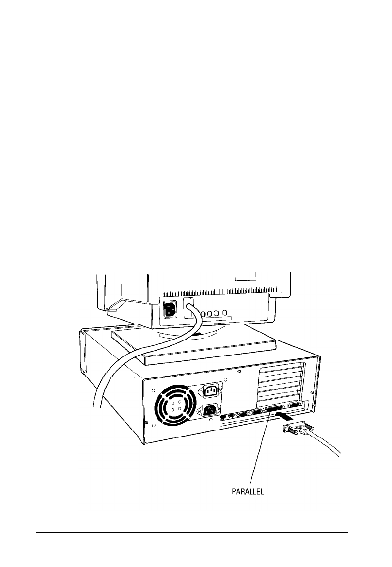
Using the Parallel Port
Follow these steps to connect a parallel printer to your
computer:
1.
Place the printer next to the computer so that the backs are
facing you.
2.
Align the connector end of the printer cable with
PARALLEL
connector has retaining screws, tighten them.
port, as shown below, and plug it in. If the
the
Setting Up Your System
1-5
Page 25

3.
Connect the other end of the cable to the printer as shown
below. To secure the cable, squeeze the clips at each side of
the printer port and push them into place.
2-6
4.
Plug the printer’s power cord into an appropriate grounded
(earthed) electrical outlet.
Setting
Up Your
System
Page 26
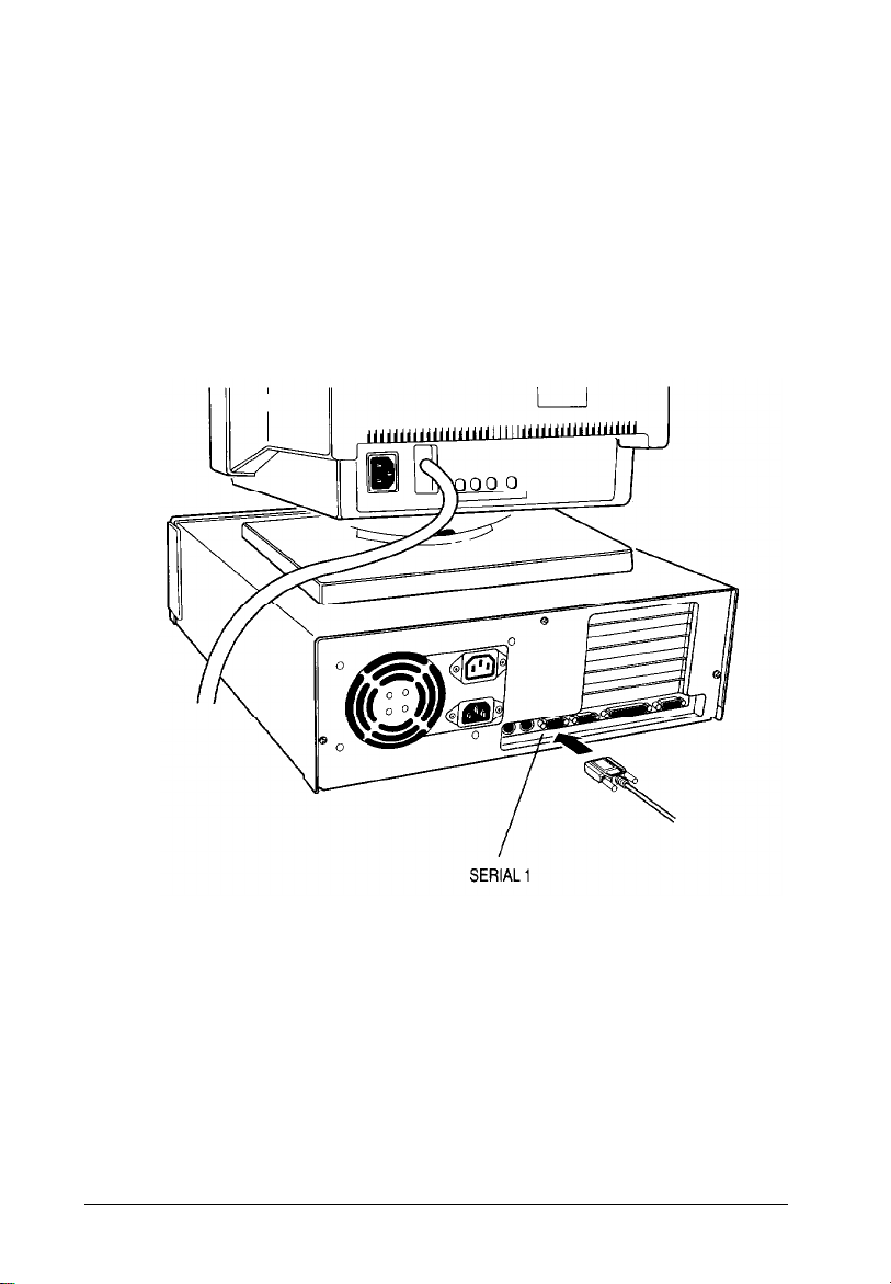
Using the Serial Ports
If you have a printer, a modem, or other peripheral device with
a serial interface, you can connect it to one of the serial
(RS-232C) ports on the back of the computer. These ports use a
DB-9P connector, so be sure you have a compatible cable.
To connect a serial device, insert the connector into one of the
ports, marked
one serial device, use the
SERIAL
1 and
SERIAL 1
SERIAL
2. If you are connecting only
port, as shown below.
Setting Up Your System
1-7
Page 27
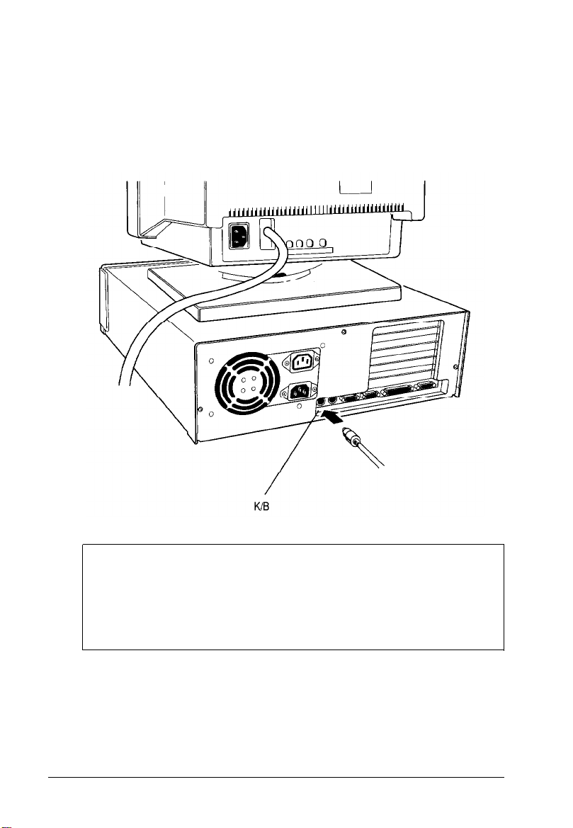
Connecting the Keyboard
4
To connect the keyboard, hold the cable connector so the arrow
on the connector faces up. Insert it into the port marked K/B, as
shown below.
1-8
Caution
Although the connectors and ports for the keyboard and
mouse are physically identical, they cannot be used
interchangeably. Be sure to plug the keyboard connector into
the keyboard (K/B) port or you could damage your system.
Setting Up Your System
Page 28

You
can
change the angle of the keyboard by adjusting the legs
on
the
bottom. Turn it over and flip each leg upward until it
locks into place. It is important to select
will prevent wrist fatigue. (You may even want to purchase a
wrist pad-sold at computer stores-for further comfort.)
To lower the keyboard, press each leg back into its slot.
Connecting the Mouse
5
Your computer includes an auxiliary port for an IBM PS/2
compatible mouse that uses a round, miniature DIN (6-pin)
connector. If your mouse has
connect it to the computer’s built-in port.
Note
If your mouse requires a different interface, connect it to the
built-in serial port or an option card that provides the
interface. Your system will properly identify the location of
your mouse.
this
the
best angle so you
type of connector, you
can
Setting Up Your System 1-9
Page 29
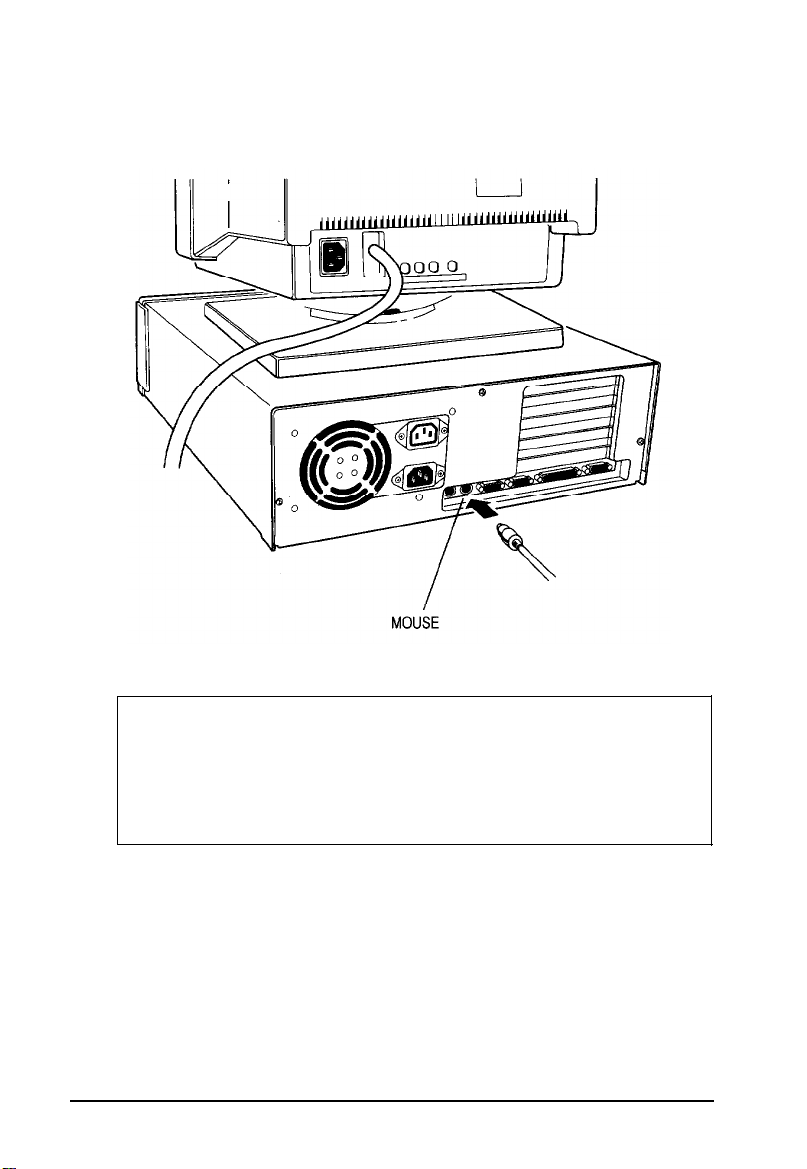
To connect the mouse to the built-in mouse port, plug the
connector into the port marked
MOUSE,
as shown below.
Caution
Although the connectors and ports for the mouse and
keyboard are physically identical, they cannot be used
interchangeably. Be sure to plug the mouse connector into
the
MOUSE
port, or you may damage your system.
If your system has not already been configured, you may need
to install a mouse driver. See your mouse manual for
instructions.
1-10
Setting Up Your System
Page 30
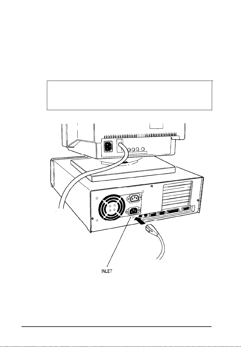
Connecting the Power Cord
6
Follow these steps to connect the power cord:
1.
Plug
the
power cord into the AC power
panel, as shown below.
WARNING
To avoid an electric shock, be sure to plug the cord into
the computer before plugging it into the wall outlet.
INLET on
the back
2.
Plug the other end of the power cord into an appropriate
grounded (earthed) electrical outlet.
Setting Up Your System
1-11
Page 31

Turning On the Computer
7
After you set up your system, you’re ready to turn on the
power. Check the following safety precautions to avoid
accidentally damaging your computer or injuring yourself:
q
Do not connect or disconnect any peripheral device cables
(including the mouse or keyboard) or power cables unless
the computer power is off.
q
Never turn off or reset your computer while a disk drive
light is on. This can destroy data stored on the disk.
q
Never turn on the computer with a protective card in the
diskette drive.
q
Always wait about 20 seconds after you turn off the power
before you turn it on again to prevent damage to the
computer’s electrical circuitry.
q
Do not leave a beverage near your system. Spilled liquid
can damage the circuitry.
Follow these steps to turn on the system:
1-12
1.
Turn your computer around so the front panel faces you.
Place your monitor, printer, and other devices in a
convenient arrangement.
2.
If there is a protective card in the diskette drive, remove it.
3.
Turn on the monitor, printer, and any other devices connected
to the computer.
Setting Up Your System
Page 32

4.
To turn on the computer, press the power button on the right
side of the front panel.
The power indicator on the left side of the front panel lights
up. After a few seconds, the screen displays a count of the
system memory, and then the computer performs a
power-on diagnostics routine to make sure everything is
working correctly.
5.
If necessary, use the controls on your monitor to adjust the
brightness and contrast until you can easily see the
characters on the screen. If your monitor has horizontal and
vertical hold controls, you may need to use them to
stabilize the display.
6.
The screen displays the following prompt:
Press <Del> if you want to run SETUP
Do not press any key yet; you just want to make sure the
computer is working. This prompt appears every time you
turn on your computer so you can run SETUP if necessary.
After a few seconds, the prompt disappears.
Setting Up Your System
1-13
Page 33

If there is no operating system installed on your computer,
you see an error message. Ignore the message for now; once
you install the operating system, you will not see this
message. If MS-DOS@ is already installed, you may see the
command prompt
(C
: \) or the menu screen of a program
such as Microsoft Windows.
Now you need to run SETUP to make sure your computer is
configured properly. First turn off the computer, as
described below, then see Chapter 2 for instructions. When
you finish running SETUP, be sure to see “Post-SETUP
Procedures” on page 2-19 for guidelines on what you need
to do next.
Turning Off the Computer
Whenever you turn off your system, follow these steps:
1.
Save your data and exit any application program you are
using.
2.
Check the hard disk drive light and the diskette drive light(s)
to make sure they are not on. Do not turn off the computer
if a drive light is on, because you can damage the drive or
lose data.
3.
Remove any diskette(s) from the diskette drive(s).
4.
Press the power button to turn off the computer.
5.
Turn off the monitor, printer, and any other peripheral
devices.
1-14 Setting Up Your System
Page 34

Chapter 2
Running the SETUP Program
The first time you use your computer, you need to run the
SETUP program to define how your system is set up. You may
need to run it again later if you change your configuration.
SETUP is stored in the computer’s read-only memory (ROM),
so you can run it any time you turn on or reset your system.
SETUP lets you verify or change the following:
q
Current date and time
q
Type of diskette drive(s) installed
q
Type of hard disk drive(s) installed
q
Type of video display adapter you are using
q
Processor speed
q
System booting sequence
q
Diskette drive seek test
q
System memory
q
Coprocessor support
q
Shadow ROM options
q
Keyboard options
q
Peripherals options
q
Password options,
Running the SETUP Program
2-1
Page 35

The configuration you define through SETUP is stored in a
special area of memory called CMOS RAM. This memory is
backed up by a battery, so it is not erased when you turn off or
reset the computer.
Whenever you reboot the computer, it checks the settings, and
if it discovers a difference between the information in the
CMOS RAM and its actual hardware configuration, it prompts
you to run SETUP. You see a message describing the error as
well as the following prompt at the bottom of the screen:
Press <Fl> to
run
SETUP or <F2> to continue
If this happens, press to run SETUP and correct the
setting.
Another SETUP option displays information about your system
board. This information provides a useful reference about
jumper and DIP switch settings, SIMM configuration, and hot
key combinations. See page 2-17 for more information.
SETUP also lets you restore the default values for your
configuration. This is useful if you have made changes but
don’t want to keep them; you can restore all the default
settings. See “Loading Default SETUP Values” on page 2-17.
2-2 Running the SETUP Program
Page 36

Starting the SETUP Program
To start SETUP, make sure there is no diskette in the diskette
drive; then turn on your computer. (If your computer is already
on, turn it off, wait 20 seconds, and then turn it on again.) After
the self test, you see the following prompt at the bottom of the
screen:
Press <Del> if you want to run SETUP
As soon as you see this message, press .
If you do not press within approximately five seconds,
the computer starts loading the operating system and you will
not be able to run SETUP. If this happens, reset the computer
and try again.
When you press [Delete), you’ll see a SETUP menu containing
these options:
1.
2.
3.
4.
5.
6.
7.
Type the number of the menu option you want to select, or use
or to move the cursor over the option you want to
select and press As you highlight each menu selection,
you’ll see a description of the option at the bottom of the screen.
Start operating system
Run SETUP
Set Password options
Display system board help
Load default SETUP values
SAVE settings and exit
Exit without saving settings
Running the SETUP Program
2-3
Page 37

Entering SETUP Options
You can verify or change all SETUP functions except
password option from menu option 2,
this option, press to highlight it, then press . YOU
see the SETUP screen.
This screen displays the size of both the base and extended
memory and whether a math coprocessor is installed. You also
see a calendar for the current month at the bottom right of the
screen.
Additionally, this screen contains system parameters you can
change.
Run
SETUP.
the
To select
Selecting Options
A solid cursor bar highlights the selected parameter. Press
to move the cursor to the
parameter you want to change. Then press or to
display the available options.
As you move the cursor to each parameter, you see a
description of the available options for that parameter at the
bottom of the screen.
The following sections describe how to choose the correct
SETUP parameters for your system.
2-4
Running
the SETUP Program
Page 38

Setting the Date and Time
The real-time clock in your computer continuously tracks the
date and time-even when the computer is turned off. Once
you set the date and time using SETUP, you should not need to
change them, unless you need to adjust the time for daylight
savings or other seasonal adjustments. (The computer
automatically changes the date for leap years.)
Use the cursor arrow keys to position the cursor over the
portion of the date or time you want to change. Press or
to modify the date or time. The time parameter uses a
24-hour clock. For example, 5 p.m. is shown as 17.
Setting the Diskette Drive(s)
Your system probably came with one diskette drive installed.
You may also have another drive of a different size or capacity.
The SETUP menu offers five possible selections for your
diskette drives (A and B):
q
360KB, 5.25-inch
q
1.2MB, 5.25-inch
q
720KB, 3.5-inch
q
1.44MB, 3.5-inch
q
Not Installed.
Check the settings for both drives and correct them if necessary.
(If you have only one diskette drive or if you install a tape drive
in the lower drive bay, select
If you install a combination (dual) diskette drive, the top drive
is A and the bottom drive is B.
Not
Installed
Running the SETUP Program 2-5
for drive B.)
Page 39

Setting the Hard Disk Drive(s)
The SETUP program lets you select the type of hard disk
drive(s) installed in your computer. If you have two hard disk
drives, the first one is C and the second one is D. Be sure to
choose the correct setting for both drives. Follow these
guidelines:
q
If your system does not have a hard disk, select None for
drives C and D. If you have only one hard disk drive, select
None for drive D.
q
If you installed a SCSI drive, select None for drive D.
q
If your computer came with an Epson 120MB hard disk
drive (or if you installed this drive yourself), select number
39 for drive C.
q
If your computer came with an Epson 170MB hard disk
drive (or if you installed this drive yourself), select number
26 for drive C.
q
If your computer came with an Epson 240MB hard disk
drive (or if you installed this drive yourself), select number
34 for drive C.
q
If you have installed another type of hard disk drive, you
need to select the drive type number that matches your
drive. See “Hard Disk Drive Types” below.
2-6 Running the SETUP Program
Page 40

Hard Disk Drive Types
The following table lists the types of standard hard disk drives
you can use. Check this table and the documentation supplied
with your hard disk to find the correct type number for your
drive. If none of the types listed matches your drive, see
“Defining Your Own Drive Type” on page 2-9.
Hard disk drive types
Running the SETUP Program
2-7
Page 41

Actual size when formatted may be slightly different than the size listed on
l
the drive label
Hard disk drive supported in translate mode
Epson drives
2-8 Running the SETUP Program
Page 42

Defining Your Own Drive Type
If the parameters for your hard disk (listed in its
documentation) do not match any of the types listed in the table
above, you can define your own type. Follow these steps:
1.
With the cursor on the drive you are defining, press
until you see type 47.
2.
Press to move the cursor into the parameter fields.
3.
Enter the appropriate values from the table below.
Drive type options
Heading
Cyln
Head
WPcom
Zone The landing zone (the area on which the computer
Sec
Description
The number of cylinders on the drive
The number of read/write heads in the drive
The precompensation cylinder
parks the heads)
The number of sectors on the drive
Press after typing each number. Check your drive
documentation for the correct value if SETUP does not
accept a value you’ve typed. SETUP provides the hard disk
size based on the other values you entered.
Setting the Primary Display Type
The Primary display
adapter you are using for your primary display. If you
connected your monitor to the computer’s built-in VGA port,
select
VGA/PGA/EGA.
following table for the correct adapter type.
option lets you define the type of
If you installed a video card, check the
Running the SETUP Program
2-9
Page 43

Video display type options
Select
VGA/PGA/EGA*
Color 40x25
Color 80x25
Monochrome
l Default setting
If
You connected your monitor to the built-in VGA port or
you installed a VGA or enhanced graphics adapter
(EGA) card
You installed an optional color graphics adapter that is
set to 40-column CGA mode
You installed a color graphics adapter (CGA) or a
multi-mode graphics adapter (MGA) attached to a
color monitor; be sure to set the color/mono switch on
the MGA card to color
You installed a monochrome display adapter (MDA).
an MGA, or a Hercules® MGA attached to a
monochrome monitor; be sure to set the color/mono
switch on the MGA card to mono
For a composite color monitor, such as a color television with
video input, try selecting Color
resolution is poor, run SETUP again and select Color
80x25. If the monitor’s
40x25.
If you have two display adapters of different types, select the
setting for the one you want to be your primary display
adapter. The other one is your secondary adapter.
If you install one type of display adapter card and then change
the adapter (from VGA to CGA or vice-versa), you also may
need to change the setting of DIP switch 5. If you have two
types of cards, set the jumper and DIP switch to match the
adapter controlling your primary display. See Chapter 4 for
instructions on changing jumper settings and the manual that
came with your monitor for additional information.
2-10
Running the SETUP Program
Page 44

Setting the Processor Speed
The System
your system. When you select
your processor’s highest speed, such as 25,33, or 50 MHz. The
Slow
compatibility with older application programs.
At fast speed, your system can access memory faster, so your
programs work faster. Select
application program that requires the slower speed. Check
your program manual.
You can also change the speed temporarily by entering a
keyboard command. See “Changing the Processor Speed” in
Chapter 3 for more information.
option simulates an 8 MHz processor to provide
speed option lets you set the default speed for
Fast,
Fast
your system operates at
unless you are using an
Setting the Booting Sequence
The booting sequence determines the order in which the
computer checks the drives when it looks for the operating
system.
For example, if you select A :
the computer it checks drive A for an operating system diskette
and loads the operating system from that diskette. If drive A
does not contain an operating system diskette, the computer
loads the operating system from drive C. This is the default
setting because you may sometimes want to boot the computer
from a system diskette in drive A.
then C,
each time you turn on
If you select C :
system from drive C and does not check drive A. This setting
allows the computer to load the operating system a little faster.
only,
the computer loads the operating
Running the
SETUP
Program
2-11
Page 45

Setting the Diskette Seek Parameter
If you enable the Diskette seek test option, the system
checks for a diskette drive during its power-on diagnostics. If
no diskette drive is connected, you see a diskette drive error.
Disable this option if you want your system to boot when no
diskette drive is connected.
Using the SETUP Screen Submenus
The SETUP screen contains three submenus that allow you to
change these settings:
q
Shadow ROM options
q
Keyboard options
q
Peripheral options.
To access the options on these submenus, move the cursor to
the
Shadow setup,Keyboard setup,
setup
that contains the options for the parameter you have selected.
parameters. You see a window to the right of the screen
or
Peripherals
Press m to move the cursor into the window. Then press
the arrow keys to move the cursor to the option you want to
change. Press or to scroll through the available
options.
Setting the Shadow Options
Your computer can access RAM (random access memory) faster
than ROM (read only memory). The Shadow feature on your
system automatically copies the contents of both the system
BIOS and the video BIOS into RAM so your system can
perform certain operations faster.
2-12 Running the SETUP Program
Page 46

Four additional shadow options allow you to shadow 32KB at
the memory addresses listed
on
the screen. You may want to
enable one or more of these shadow options if, for example,
you are using option cards that contain ROM. You
can
the memory on the card to your system’s RAM using these
options. Check the memory map on page A-6 and the
documentation that came with your option card to determine
which addresses your option card can access. You may also
need to set some switches or jumpers on the option card.
Setting the Keyboard Options
There are four options for the keyboard: Test, NumLock,
Key rate, and Key delay. The table below describes the settings
available.
Keyboard options
shadow
Option
Test
NumLock
Key rate
Key delay
l Default setting
Settings
Enabled’
Disabled
On*
Off
2.0-30.0
(characters per
second)
0.25-1.OO
(seconds)
Description
Tests keyboard at power-on
Skips keyboard test at power-on
Determines initial NumLock
status when system is turned on
or reset
Sets rate at which a character
repeats when key is held down;
default is 10.9
Sets period of delay between
the time a key is pressed and the
character appears on the
screen; default is 0.50
Running the SETUP Program 2-13
Page 47

Setting the Peripherals Options
The
Peripherals
for the built-in interface ports and disk drive controllers. You
may need to change these settings if you install an interface on
an option card. The following table lists the possible settings.
I/O control options
setup
option lets you change the settings
Peripherals option Setting
Serial
Parallel Uni-LPT1*
PS/2 mouse
On-B/D FDC
IDE HDC Enabled’
COMl+2*
COM1
COM2
Disabled
Uni-LPT2
Bi-LPT1
Bi-LPT2
Disabled
Enabled*
Disabled
Enabled*
Disabled
Disabled
Description
Sets serial port 1 as COM 1 and
serial port 2 as COM2
Sets serial port 1 as COM1,
disables port 2
Sets serial port 1 as COM2,
disables port 2
Disables both of the serial ports
Sets parallel port as unidirectional
LPT1
Sets parallel port as unidirectional
LPT2
Sets parallel port as bidirectional
LPT1
Sets parallel port as bidirectional
LPT2
Disables the on-board parallel port
Enables the PS/2 mouse port
Disables the PS/2 mouse port
Enables the on-board diskette
drive controller
Disables the on-board diskette
drive controller
Enables the on-board hard disk
drive controller
Disables the on-board hard disk
drive controller
l Default setting
2-14 Running the SETUP Program
Page 48

Setting the Password Options
SETUP lets you enter a new password or disable an existing
password to control who can access your system. A second
password option allows you to set a hot key to disable your
keyboard and mouse until you enter your system password.
Entering a Password
Follow these steps to enter a password:
Select option 3, Set Password options, from the main
1.
menu.
Press until you see
2.
the
Password
Enter password
Enter the password you want to use and press The
3.
password can be up to eight characters and/or numbers.
As you type the password, the screen displays an asterisk
for each character you type.
The cursor moves to the second Enter
4.
field. Type your password again and press . You
again see an asterisk for each character you type.
When you type the same password choice, you see the
message:
Correct! password installed
As you exit SETUP, make sure you save the new settings.
5.
When the system reboots, you will see the password
prompt.
state option. The cursor moves to the
New Install
option field.
displayed for
password
option
Running the SETUP Program
2-15
Page 49

Changing or Deleting a Password
If you want to change
as to enter a new password. When the cursor is at the
Enter
use.
To delete a password, select
Password state option.
Whenever you delete your password using
you
password
save the new
your password,
option, type the new password you want to
Not
settings
as you exit the SETUP program.
follow the same steps
Installed
for the
SETUP, make
Setting the Keyboard Lock Option
SETUP provides another level of security for your system in the
keyboard lock function. Once you have set a password for your
system, you can also set a hot key that, when you press it, locks
the keyboard and mouse until you enter your password again.
Follow these steps to define the hot key for your keyboard lock
option:
1.
On the password setup screen, move the cursor to the
Hot key state option.
sure
2. Press until
to
the
Enter’ Hot key'
3.
Enter a letter or a number and press This identifies
the key you want to press together with and
as the hot key to lock your keyboard.
4.
As you exit SETUP, make sure you save the new settings.
When you press the hot key you’ve defined, the keyboard
and mouse lock until you enter your password.
2-16 Running the SETUP Program
you see New Install.
The cursor moves
option field.
Page 50

Using the System Board Help Function
SETUP provides a system board help function that contains a
diagram of your system board in addition to the following
information:
DIP switch settings
qq
qq
Jumper settings
qq
Identification of connectors
qq
Correct SIMM configurations
qq
External cache configurations
qq
Hard disk drive types
System key combinations.
qq
To use this help function, select option 4, Display system
board help, from the main menu. Use the arrow keys to
scroll through the options. You see the help information for the
selected option in a window at the lower right corner of the
screen.
Loading Default SETUP Values
You can load the default SETUP values at any time by selecting
option
this option, you see this message:
Press , then to load the default values. If you don’t
want to load the default values, press , then . You can
select another option from the SETUP main menu, or exit
SETUP.
5, Load default SETUP values.
Load BIOS setup default values (Y/N)?
Running the SETUP Program
Whenyouselect
2-17
Page 51

Saving Your Settings and Exiting SETUP
When you leave SETUP, you can either save the settings you
have changed or exit the program without saving any changes.
To save your settings, follow these steps:
1.
Press to return to the main SETUP menu.
2. Select option 6, SAVE settings and exit, and
press [Enter. You see this message:
Write to CMOS RAM and exit (Y/N)?
3.
Press and The system reboots.
4.
If you have just run SETUP for the first time, see “Post-SETUP
Procedures,” below.
To exit SETUP without saving the setting, select option 7,
Exit without saving settings. The system reboots with
your original settings.
Note
If your computer detects a problem in your SETUP
configuration, you may see an error message and a prompt
to run SETUP when it is rebooting. Follow the instructions
on the screen to run SETUP and correct the problem.
You may also see an error message when your computer is
rebooting if you have not installed your operating system on
the hard disk and you did not insert a system diskette in
drive A. If you receive this error message, follow the
instructions in your operating system manual to install it.
2-18 Running the SETUP Program
Page 52

Post-SETUP Procedures
If you have just run SETUP for the first time and your system
has not been configured, you now need to install the operating
system on your computer. See your operating system manual
for instructions.
After you have installed your operating system, you can install
any software you plan to use. See your application program
manuals for instructions.
The VGA Utilities diskette contains special drivers to enhance
the display capabilities of your built-in VGA adapter with
certain applications. If you want to install these drivers, see the
readme file called VGADRV.TXT in the root directory of the
VGA Utilities 1 diskette. To print this file, enter the following
command at the DOS prompt:
COPY A:VGADRV.TXT LPTl
If your computer came configured with a hard disk, the
README file may already be loaded on the hard disk. You can
access it by loading Windows and clicking on the VGA Utils
group icon. Then select the README file icon.
Running the SETUP Program 2-19
Page 53

Chapter 3
Using Your Computer
This chapter briefly describes the following operations:
q
Working comfortably
q
Using disks and disk drives
q
Using special keys on the keyboard
q
Stopping a command or program
q
Resetting the computer
q
Using a password
q
Using the hot key feature
q
Changing the processor speed.
Working Comfortably
This section provides tips for creating a comfortable work
environment. Following these guidelines for good posture,
work habits, and workstation layout can help you avoid
problems such as muscle aches, eyestrain, and fatigue.
Using Your Computer
3-1
Page 54

Sitting at Your Computer
When you use the computer, try to keep your elbows, hips, and
knees bent at approximately 90 degree angles and keep your
wrists as close to horizontal as possible. (Your hands, forearms,
and thighs should be horizontal and your upper arms and
lower legs should be vertical.) Your feet should rest firmly on
the floor or a footrest.
An adjustable chair allows you to customize your workstation
for your body so you can maintain the right posture. To avoid
back problems, make sure your chair supports your lower back.
Padded armrests let you rest your arms as you work.
To reduce neck strain, keep source documents on a copy stand
and position the stand next to the screen at the same eye level.
3-2
Using Your Computer
Page 55

Work in a relaxed, natural, upright position and let the chair
support you. Your elbows should be near your body and level
with or slightly lower than the keyboard so your hands rest
lightly on the keys. To help you keep your wrists straight, the
slope of the keyboard should be no more than 25 degrees. Try
not to hit the keys too hard; using too much force creates
tension in your hands. Also leave enough room on your work
surface so you can freely move the mouse (or other pointing
device), and be sure to rest your hands occasionally.
Varying Your Posture and Movements
While sitting at the computer, try to vary your posture and
movements. Your seat and backrest should be wide enough
and there should be enough room under your desk so that you
can sit in a variety of positions throughout the day.
Be sure to occasionally stop working at your computer and
perform other tasks. Also take periodic breaks; stand up,
stretch, and move around.
Lighting the Room
While it is important to have adequate lighting in your work
area, make sure it is not too bright. When a light source is very
bright, your eyes get tired by having to continually readjust
between the relative dimness of the screen and the bright
surroundings. It is best to control the amount of daylight that
enters the room and keep bright light sources out of your field
of vision when you are looking at the screen.
Using Your
Computer
3-3
Page 56

Positioning and Viewing the Monitor
Place the monitor directly in front of you and sit about an arm’s
length away from it. To minimize glare and reduce eye fatigue,
position the monitor so that sunlight, desk lamps, and
overhead lights do not shine directly on the screen.
When you are sitting in front of the monitor, the top of the
screen should be slightly below eye level so you look down,
rather than up, at the screen. If your monitor is too low, you
can raise it by placing it (or the computer) on a stand. If the
monitor has a tilt and swivel base, you can use it to adjust the
position of the screen for comfortable viewing.
To produce an image that is clear and easy to look at, adjust the
monitor’s brightness and contrast controls. If your screen
flickers, you can minimize it by selecting a dark background
using either the brightness and contrast controls or your
software.
To prevent eyestrain, rest your eyes occasionally by closing
them or focusing on a fixed spot in the distance.
3-4
Using Your Computer
Page 57

Using Disks and Disk Drives
The disk drives in your computer allow you to store data on
disk, and then retrieve and use your stored data. This section
tells you how to:
Choose the right diskettes for your drive
Write-protect diskettes
Insert and remove diskettes
Use a single diskette drive system
Format diskettes
Make backup copies
Care for diskettes
Use a hard disk drive.
Types of Diskette Drives
Your system supports the following types of diskette drives:
q
1.44MB, 3.5-inch
q
1.2MB, 5.25-inch
q 72OKB, 3.5-inch
q
360KB, 5.25-inch
q
Dual 1.44MB, 3.5-inch and 1.2MB, 5.25-inch.
Using Your Computer
3-5
Page 58

Note
MB stands for megabyte, which equals 1024KB (or 1,048,576
bytes). KB stands for kilobyte, which equals 1024 bytes. Each
byte represents a single character, such as A, $, or 3.
If your computer has more than one type of diskette drive, or if
you use different types of diskettes, you need to be aware of
certain incompatibilities between the drives and diskettes. See
the following tables.
3.5-inch drive/diskette compatibility
Drive type
720KB 720KB
1.44MB
Diskette types it can read from and write to
1.44MB, 720KB
5.25-inch drive/diskette compatibility
Drive type
360KB
1.2MB
l If you write to this diskette in a 1.2MB drive, you may not be able to read it
or write to it in a 360KB drive later.
Diskette types it can read from and write to
360KB. 320KB. 180KB. 160KB
1.2MB. 360KB,* 320KB,* 180KB,* 160KB*
Because of possible incompatibilities, always label your
diskettes with the diskette type and density. (Usually this
information appears on the manufacturer’s label.)
Note
If you want to format a 720KB diskette in a 1.44MB drive or a
360KB diskette in a 1.2MB drive, make sure you include the
correct parameter in your format command. (In Windows
you need to select the drive capacity.) See your operating
system manual for instructions.
3-6
Using Your Computer
Page 59

Write-protecting Diskettes
You can write-protect a diskette to prevent its data from being
altered. When a diskette is write-protected, you can read it and
copy data from it, but you cannot store new data on it or delete
any files it contains.
On a 3.5-inch diskette, the write-protect device is a small switch
on the back of the diskette in the lower right corner, shown
below. To write-protect a 3.5-inch diskette, slide the switch
toward the edge of the diskette until it clicks into position,
exposing a hole in the corner.
To remove the write protection, slide the switch toward the
center of the diskette until it clicks into position and the hole is
covered.
Using Your Computer
3-7
Page 60

To write-protect a 5.25-inch diskette, cover the small,
rectangular notch (shown below) with an adhesive
write-protect tab. Write-protect tabs usually are included in
a new package of blank 5.25-inch diskettes.
To remove the write protection, peel off the write-protect tab.
Some program diskettes have no switch or notch so they are
accidentally erased or altered.
3-8
Using Your Computer
Page 61

Insertting and Removing Diskettes
To insert a diskette into a 3.5-inch drive, hold the diskette with
the label facing up and the metal shutter leading into the drive,
as shown in the following illustration. Slide the diskette into the
drive until it clicks into place.
To insert a diskette into a 5.25-inch drive, hold the diskette with
the label facing up and the read/write slot leading into the
drive. When you want to remove the diskette, make sure the
drive light is off; then press the release button or flip up the
latch. When the diskette pops out, remove it and store it
properly.
Caution
Never remove a diskette or reset or turn off the computer
while a diskette drive light is on. You could lose data. Also,
remove all diskettes before you turn off the computer.
Using Your Computer
3-9
Page 62

Using a Single Diskette Drive System
Most operating systems expect the computer to have at least
two diskette drives and display prompts and messages
accordingly. MS-DOS, for example, recognizes the first diskette
drive (the top drive) as drive A and a second diskette drive as
drive B. If you have only one diskette drive, MS-DOS can treat
it as both A and B when you need to perform operations that
normally would use two diskette drives.
For example, if you enter a command to copy data from A to B,
MS-DOS copies the data from the first diskette you place in the
drive (which would be drive A) to the computer’s memory.
Then MS-DOS prompts you to insert another diskette (for
drive B) and copies the data from memory to the new diskette.
When copying is complete, you see a prompt to insert the
original diskette (A).
Because you may often swap diskettes this way, it is important
to remember which diskette is which. It is also a good idea to
write-protect your original diskette. (See “Write-protecting
Diskettes,” on page 3-7.)
If you have a hard disk and one diskette drive, you can load the
operating system and application programs from the hard disk,
create and store your data there, and use the diskette drive just
for copying data to or from diskettes.
However, if you have only one diskette drive and no hard disk,
you need to use that drive to load the operating system as well
as any application program you are using. First, insert the
operating system diskette in drive A and load the operating
system; this copies it to the computer’s memory (RAM) so you
do not need to leave the system diskette in the drive. Then
remove the system diskette and insert your application
program diskette to load that data into memory, too. See your
application program manual for detailed instructions.
3-10
Using
Your Computer
Page 63

Formatting Diskettes
Before you can store data on a new diskette, you must format it.
Formatting prepares the diskette so that the operating system
can write data on it. You need to do this only once, before you
use the diskette for the first time.
You can also reformat previously used diskettes to store new
data. This process erases all the data on the diskette, so be sure
you do not want to save any of the files on a used diskette
before you format it. See your operating system manual for
instructions on formatting diskettes.
Making Backup Copies
It is important to make copies of all your data and system
diskettes. Make backup (or working) copies of all diskettes that
contain programs, such as your operating system and VGA
Utilities diskettes; then use only the copies. Store the original
diskettes away from your working diskettes. Also, copy your
data diskettes regularly, whenever you revise them, and store
them away from your originals.
If you have a hard disk, you’ll probably use it to store the
programs and data files you use regularly. Keep backup copies
of all your files on diskettes or tapes (if you have a tape backup
drive).
Using Your Computer
3-11
Page 64

Caring for Diskettes
Follow these simple precautions to safeguard your data and
lengthen the life of your diskettes:
q
Avoid leaving diskettes near magnetic fields that can erase
the data, such as those generated by electric appliances or
cordless telephones. Never place a diskette on top of your
monitor or near the hard disk drive.
q
Small particles of dust or dirt can scratch the magnetic
surface, destroy data, and ruin the read/write heads in a
diskette drive, so store diskettes in a diskette container
away from dust and dirt.
q
Extreme changes in temperature can also destroy data.
Keep diskettes out of direct sunlight or extreme cold.
See your diskette packaging for other guidelines.
Using a Hard Disk Drive
Using a hard disk is similar to using a diskette. However, the
hard disk provides several advantages:
q
A hard disk can store many times more data than a diskette.
q
Your computer can perform all hard disk operations faster.
q
You can store frequently used programs and data files on
the hard disk, eliminating the inconvenience of swapping
diskettes to access different files.
The added storage capacity makes it easy to move back and
forth between different programs and data files. However,
because it is so easy to add programs and files to your hard
disk, you may find yourself trying to organize hundreds of files.
3-12 Using Your Computer
Page 65

Most operating systems let you keep related files together in
directories and subdirectories so they are easy to find and use.
See your operating system manual for instructions on
managing your files and directories.
Note
A hard disk must be partitioned and formatted before you
can use it. Be sure you have performed the procedures
described in your operating system manual to prepare your
hard disk for use.
Backing up the hard disk
While the hard disk is very reliable, it is essential to back up
your hard disk files to diskettes or tapes in case you lose some
data accidentally. Make copies of all your system and
application program diskettes before copying the programs to
the hard disk. Be sure to to back up your data files regularly to
keep your backup diskettes or tapes up-to-date.
Curing for your hard disk
Follow these precautions to protect your hard disk drive from
damage and to avoid losing data:
q
Never turn off or reset the computer when the hard disk
access light is on. This light indicates that the computer is
copying data to or from the hard disk. If you interrupt this
process, you can lose data.
q
Never attempt to open the hard disk drive. The disk itself is
enclosed in a sealed container to protect it from dust.
Using Your Computer
3-13
Page 66

Special Keys on the Keyboard
Certain keys on your keyboard serve special functions when
your computer is running your operating system or application
programs, as described in the table below.
3-14
Using Your Computer
Page 67

Special key functions (continued)
The and key work as toggles; press
the key once to turn on a function and again to turn it off. When
the function is enabled, the corresponding light in the upper
right corner of the keyboard is on.
Stopping a Command or Program
You may sometimes need to stop a command or program while
it is running. If you have entered an MS-DOS or application
program command that you want to stop, try one of the
following:
q
q
q
If these methods do not work, you may need to reset the
computer as described below. Do not turn off the computer to
exit a program or stop a command unless you have to, because
the computer erases any data you did not save.
Press
Hold down the key and press
Hold down the key and press
Using Your Computer
3-15
Page 68

Resetting the Computer
Occasionally, you may want to clear the computer’s current
settings or its memory without turning it off. You can do this
by resetting the computer.
For example, if an error occurs and the computer does not
respond to your keyboard entries, you can reset it to reload
your operating system and try again. However, resetting erases
any data in memory that you have not saved; so reset only if
necessary.
Caution
Do not reset the computer to exit a program. Some programs
classify and store new data when you exit them in the
normal manner. If you reset the computer without properly
exiting a program, you may lose data.
To reset the computer, the operating system must be either on
the hard disk or on a diskette in drive A; so if you do not have a
hard disk, insert the system diskette in drive A. If you are using
MS-DOS, hold down and and press The
screen goes blank for a moment and then the computer should
reload your operating system.
If resetting the computer does not correct the problem, you
probably need to turn it off and reboot it. Remove any
diskette(s) from the diskette drive(s). Turn off the computer
and wait 20 seconds. If you do not have a hard disk, insert the
system diskette in drive A. Then turn on the computer.
3-16
Using Your Computer
Page 69

Using a Password
If you set a system access password when you ran the SETUP
program, you must enter it every time you turn on or reset the
computer. Follow these steps to use your password:
1.
If you do not have a hard disk, insert your system diskette
in drive A.
2.
Turn on or reset the computer. You see the following prompt:
Enter Password:
3.
Type your password and press
After you type the password correctly and press the
computer loads the operating system and displays the
command prompt.
Note
If you do not know the correct password, see “Password
Problems” in Chapter 6.
Using the Hot Key Feature
Once you set a password, you can keep unauthorized users
from accessing your system by using the hot key feature. This
key combination the key of your choice)
temporarily locks your keyboard and mouse so you can secure
your system without turning it off.
To use the hot key feature, follow these steps:
1.
See Chapter 2 to set your password and define a hot key.
Using Your Computer
3-17
Page 70

2.
When you want to disable the keyboard and mouse, enter
your hot key combination. The keyboard and mouse lock
up and do not respond to typed entries or mouse
movement.
3.
To resume activity, type your password and press .
Changing or Deleting a Password
To change or delete your password, you must run the SETUP
program and follow the instructions for entering a password in
Chapter 2.
If you do not know your password, see “Password Problems”
in Chapter 6.
Changing the Processor Speed
Your computer’s processor can operate at two speeds: fast
or slow. Fast speed is the highest speed at which your
microprocessor is capable of running, such as 25,33, or
50 MHz. Slow speed simulates an 8 MHz processor to provide
compatibility with older application programs.
When your computer is operating at fast speed, the speed light
on the front panel is green. When the computer is operating at
slow speed, the light is amber.
You should use fast speed for almost everything you do
because your programs will work faster. However, certain
application programs have specific timing requirements and
can run only at the slower speed. See your software manual to
determine if this is the case.
3-18
Using Your Computer
Page 71

If you want your computer to always start at slow speed, you
can change the default setting through SETUP. See Chapter 2
for instructions.
Some copy-protected programs require the computer to run at
slow speed while accessing the program on a diskette. These
programs also usually require you to leave a key disk-the
diskette that contains the copy protection-in the diskette
drive. If you use a copy-protected program, you can change the
speed to slow to access the diskette and return it to fast speed
when you are finished.
You can change the processor speed temporarily by entering
one of the following commands from the numeric keypad on
your keyboard:
q
To select slow speed, press
q
To select fast speed, press
(Hold down the key and the key simultaneously
and then press the or key on the numeric keypad.)
Note
You can use the commands listed above while you are
running a program. However, if the program uses one of
these commands for another function, you cannot use it to
change the processor speed. You can, however, enter the
command at the MS-DOS command prompt or change it
through the SETUP program.
The speed setting remains in effect until you reset the
computer, change the speed with a keyboard command, or
change the speed using SETUP.
Using Your Computer 3-19
Page 72

Chapter 4
Installing and Removing Options
You can enhance the performance of your computer by adding
optional equipment such as memory modules, option cards, an
Intel OverDrive processor or math coprocessor, or video
memory.
This chapter describes how to install (and remove) these
options, as well as how to change the jumper and DIP switch
settings inside the computer. You may need to change these
settings if you install options or if you want to change the way
your system operates.
Installing and Removing Options
4-1
Page 73

How to Use This Chapter
This chapter explains how to do the following:
q
Remove and replace the computer’s cover
q
Change jumper settings and DIP switch settings on the
main system board
q
Install and remove memory modules (SIMMs)
q
Install and remove an option card
q
Remove and replace the option card connector board
q
Install a new processor chip
q
Increase the video memory
q
Use the VGA feature connector
q
Replace the system battery.
Follow the steps in the first section to remove the cover, and
then go to the appropriate section for the instructions you need.
When you finish, see the instructions at the end of this chapter
to replace the computer’s cover.
Note
Your system also supports up to 256KB of extended cache
memory; however, the system board must be removed from
the computer to install the cache memory chips. If you want
to add cache memory, contact your Authorized Epson
Servicer or call the Epson Connection for a referral. Do not
attempt to install cache chips yourself.
4-2
Installing and Removing Options
Page 74

Locating the lnternal Components
As you follow the instructions in this chapter, refer to the
following illustration to locate the different components inside
your computer.
Installing and Removing Options
4-3
Page 75

Removing the Cover
You need to remove the computer’s cover to install any of the
options described in this chapter or to install or remove a disk
drive (as described in Chapter 5). Follow these steps:
1.
Turn off the computer and then any peripheral devices
(including the monitor and printer).
2.
Disconnect the computer’s power cable from the electrical
outlet and from the back panel. Also disconnect any cables
that are connected to the computer, including the keyboard
and mouse cables.
If the monitor is on top of the computer, lift it off and set it to
3.
one side.
4.
Remove the three screws securing the back panel, as shown
below.
4-4
Installing and Removing Options
Page 76

From the front of the computer, grasp the sides of the cover
5.
and pull it straight toward you until it stops, just before it
reaches the front of the computer. Then lift it off at an angle
as shown below.
Set the cover aside.
6.
Ground yourself to the computer by touching the metal
7.
surface of the back panel.
WARNING
Be sure to ground yourself by touching the back panel of the
computer every time you remove the cover. If you are not
properly grounded, you could generate an electric shock that
could damage a component when you touch it.
Installing and Removing Options
4-5
Page 77

Changing the Jumper and DIP Switch Settings
The main system board in your computer has a number of
jumpers and DIP (Dual Inline Package) switches. These devices
control the operation of your system and provide configuration
information to your CMOS ROM.
The jumpers control the following functions:
q
Enable or disable the built-in VGA display adapter
q
Specify the type of CPU installed
q
Specify the amount of external cache.
The DIP switches control these functions:
q
Specify a color or monochrome monitor
q
Specify the type of CPU installed on your system board
q
Enable or disable the password
q
Select the processor speed.
Jumpers and DIP switches are preset at the factory to match
your system’s configuration, but you may need to change them
when you install certain options or want to change some
functions. The following tables list the jumpers and DIP
switches inside your system.
4-6
Installing and Removing Options
Page 78

Display adapter and CPU jumper settings
Jumper
J3 A*
J4
* Factory setting
Setting
B
**
A
B
** Factory set according to system CPU
Function
Enable the built-in VGA adapter
Disable the built-in VGA adapter so
you can use a display adapter on an
option card as your primary adapter
Select DX or DX2 CPU
Select SX CPU
External cache jumper settings
*
Factory setting; change jumpers only if external cache chips are installed
by servicer
DIP switch settings
Switch
**
1
**
2
**
3
4
5
* Factory setting
Setting
ON
OFF
ON
OFF
ON CPU present in PGA socket
OFF CPU absent from PGAsocket
ON*
OFF
ON*
OFF Select monochrome monitor
** Factory set according to system type
Function
33 MHz CPU speed
25 MHz CPU speed
25 MHz CPU speed
33 MHz CPU speed
Enable’password security feature
Disable password security feature
Select color monitor
Installing and Removing Options
4-7
Page 79

Setting the Jumpers
If you need to change any jumper settings, follow these steps:
1.
Refer to the illustration on page 4-3 to locate the jumpers,
2.
If there are any option cards installed, and you want to
change the setting for jumper J3, you may need to remove
the cards. See page 4-19.
3.
A jumper’s setting is determined by where the jumper is
placed on the pins. For three pin jumpers, the jumper
connects pin 1 and the middle pin (position A) or pin 3 and
the middle pin (position B), as shown below.
In the off position, a three pin jumper sits on only one of the
end pins. To move a jumper from one position to the other,
use needle-nose pliers or tweezers to pull it off its pins and
gently move it to the desired position.
I
Caution
Be careful not to bend the jumper pins or damage any
surrounding components on the main system board.
4.
Replace any option cards you removed. See page 4-14 for
instructions.
4-8 Installing and Removing Options
I
Page 80

Setting the DIP Switches
If you need to change any of the DIP switch settings, follow
these steps:
Locate the DIP switch block near the center of the system
1.
board, shown on page 4-3. The switches are numbered
1 through 5, and the ON position is marked on the block.
Use a pointed instrument, such as the tip of a pen, to turn a
2.
DIP switch on or off. The new setting takes effect the next
time you turn on the computer.
Depending on which DIP switch you change, you may also
3.
need to run SETUP. For example, if you set DIP switch 4 to
ON to enable password security, you then need to enter
your password using
See Chapter 2 for instructions.
Set Password options
in SETUP.
Installing and Removing Options
4-9
Page 81

Memory Modules (SIMMs)
Your computer comes with 4MB of memory installed on the
system board. By installing memory modules-also called
SIMMs-you can increase the amount of memory in your
computer up to 36MB.
There are two SIMM sockets on the main system board, and
each can contain one memory module. You can install SIMMs
with a capacity of lMB, 4MB, or 16MB.,The following table
shows the possible SIMM configurations; do not install
memory in any other configuration.
SlMM confiqurations
*
Standard memory on the system board
** SlMMs can occupy either socket
4-10
Installing and Removing Options
Page 82

Before you install SIMMs, check the following guidelines to
ensure that they will work properly:
q
Use only 36-bit, 72-pin, fast-page mode SIMMs that operate
at an access speed of 70ns (nanoseconds) or faster. Be sure
all the SIMMs operate at the same speed.
q
Your computer can use any SIMM that complies with
industry standards; however, it is best to use Epson SIMM
option kits to ensure reliability and compatibility.
lnserting SlMMs
Follow these steps to install SIMMs:
1.
Refer to the illustration on page 4-3 to locate the SIMM
sockets near the front of the computer.
2.
Remove any option cards that may be blocking your access to
the SIMM sockets. See page 4-19 for instructions.
3.
Position the SIMM over the socket at an angle, as shown
below. The components on the SIMM should face the
outside of the computer.
Installing and Removing Options
4-11
Page 83

4.
Push the SIMM into the socket until it is seated firmly in the
slot. Then tilt it upright, as shown below, guiding the hole
at each end of the SIMM over the retaining post at each end
of the SIMM socket.
If it does not go in smoothly, do not force it; pull it all the way
out and try again.
4-12
5.
Repeat steps 3 and 4 for the second SIMM, if necessary.
6.
Replace any option cards you removed. See page 4-14 for
instructions.
7.
The next time you turn on your computer, run the SETUP
program so your computer can update its configuration
information with the new memory. See Chapter 2 for
instructions.
Installing and Removing Options
Page 84

Removing SlMMs
If you need to remove SIMMs from your computer (to install
different ones, for example), follow the steps below.
1.
Remove any option cards that may be blocking your access to
the SIMM sockets. See page 4-19 for instructions.
2.
Use your fingers or a small screwdriver to carefully release
the metal tabs that secure the SIMM at each end. As you
release the tabs, the SIMM falls to the side. Remove it from
the socket.
3.
If necessary, follow the same procedure to remove the other
SIMM.
4.
Replace any option cards you removed as described on page
4-14.
5.
The next time you turn on your computer, run the SETUP
program so your computer can update its memory
configuration.
Installing and Removing Options
4-13
Page 85

Installing an Option Card
This section explains how to install an option card in your
computer. Your computer has four option slots to
accommodate up to four 8-bit or 16-bit option cards.
Usually it does not matter which slot an option card occupies as
long as the card fits in the slot. For example, you can place
some 8-bit cards in a 16-bit slot. However, follow these
guidelines when deciding which slot to use:
q
If you are installing a display adapter card, make sure any
switches or jumpers on the card are set properly. See the
documentation that came with the card for instructions.
q
If you installed SIMMs, the bottom slot (slot 1) will
accommodate only an 8-bit card.
q
If you are using a CGA adapter and monitor, you also need
to set the
Color 80x25 or Color 40x25. See Chapter 2 for
instructions on running SETUP.
q
If you are installing a high-resolution graphics adapter
card, follow the instructions below to install the adapter
card; then see “Using the VGA Feature Connector” on page
4-17 to connect the card to the VGA feature connector on
the main system board.
Primary
display
option in SETUP to
Note
Before you install an option card, see if you need to change
any jumper settings or DIP switches on the system board.
For example, if you install a video card, you may need to
change jumper J3. See page 4-6.
4-14 Installing and Removing Options
Page 86

Follow these steps to install an option card:
1.
If you are installing a card in the option slot for the first time,
you need to remove the metal cover for that slot on the
inside back panel. Remove the retaining screw securing the
option slot cover to the computer. (Keep the screw to secure
the option card to the computer.)
2.
Slide out the slot cover and set it aside. (Store the slot cover in
a safe place in case you remove the option card later.)
3.
Unpack the option card and adjust any switches or jumpers
on it, if necessary. (Check the option card instructions.)
When you handle the card, do not touch any of the
components on the circuit board or the gold-edged
connectors. If you need to set it down before you install it,
place it gently on top of its original packing material with
the component side facing up. Keep the packing materials
in case you remove the card later.
Installing and Removing Options 4-15
Page 87

Hold the card along the top corners and guide it into the
4.
connector, as shown below.
4-16
Once the connectors reach the slot, push the card in firmly
(but carefully) to insert it fully. You should feel the card fit
into place. If it does not go in smoothly, do not force it; pull
the card all the way out and try again.
Secure the end of the card to the computer with the retaining
5.
screw.
Installing and Removing
Options
Page 88

Using the VGA Feature Connector
Your computer includes an alternate VGA interface (feature
connector) on the main system board. If you install a
high-resolution graphics or a full-motion, multi-media adapter
card in one of the computer’s option slots, this connector allows
you to access the standard VGA signals provided by your
system circuitry.
Typically, high-resolution graphics adapter cards increase the
graphics processing performance of your VGA monitor and
provide resolutions of more than 1024 x 768. They are useful for
high-end graphics applications such as AutoCAD® or Windows.
Memory” on page 4-25 for information.
To connect the adapter card interface to the VGA feature
connector on your main system board, locate the VGA feature
cable included with your computer. Then follow these steps:
1.
If you have not already done so, follow the instructions on
page 4-14 (“Installing an Option Card”) to install the
graphics adapter card in your computer.
Installing and Removing Options
4-17
Page 89

2.
Attach one end of the feature cable to the alternate VGA
interface on the main system board near the back panel, as
shown below. Align the cable so the red wire along one
edge is closest to pin 1 in the socket.
3.
Connect the other end of the cable to the appropriate
interface on the adapter card. (Check your graphics card
manual for instructions.)
4-18
installing and Removing Options
Page 90

Removing an Option Card
You may need to remove an option card installed in your
computer to access components on the main system board-to
change a jumper setting, for example. You may also want to
remove a card if you no longer need it. Follow these steps:
1.
Remove the retaining screw securing the option card to the
computer. Then pull the card straight out of the slot.
2.
Set the card aside with the component side facing up.
When you are ready to re-install the option card, see page 4-14
for instructions.
Installing and Removing Options
4-19
Page 91

Removing the Option Card Connector Board
You may want to remove the option card connector board to
access certain components on the main system board, such as
the disk drive controllers. Follow these steps:
1.
Remove any option cards. (See the instructions above.)
2.
Remove the retaining screw securing the bracket on the
option card connector board to the power supply.
4-20
3.
Pull the board straight up and out of its socket and set it aside.
Installing and Removing Options
Page 92

Replacing the Option Card Connector Board
If you removed the option card connector board to access any
system components, refer to the illustration on page 4-14 as you
follow these steps:
1.
Position the board above its slot and then firmly push it
straight in.
2.
Secure the board to the power supply with its retaining screw.
Now you can re-install any option cards you removed. See
page 4-14 for instructions.
Installing a New Processor Chip
You can enhance your 25 MHz or 33 MHz system’s
performance by installing an Intel OverDrive processor.
Alternatively, for the 25 MHz system, you can install a
487SX microprocessor with a built-in math coprocessor.
An OverDrive processor is a CPU chip which doubles the
internal processing speed of the microprocessor and includes a
built-in math coprocessor. A math coprocessor is an optional
microprocessor for 486SX systems that allows them to perform
some mathematical functions faster.
Installing and Removing Options
4-21
Page 93

Complete instructions for installing the processor are provided
in the manual that comes with it. Please follow those
instructions carefully, along with the following guidelines:
q
Although the OverDrive processor User’s Guide instructs
you to remove the main system board from the computer,
this is not necessary. You can leave the board inside the
computer case while you install the processor.
Refer to the illustration on page 4-3 to locate the
q
microprocessor socket on the system board. You can install
the OverDrive processor (or 487SX chip) directly in this
socket; however, you need to remove the current
microprocessor first. To remove the microprocessor chip,
follow the instructions in the next section.
q
When you install an OverDrive processor, you need to
change the jumper setting of J4 to position A.
q
After you install the processor and replace the computer’s
cover, run the SETUP program so your computer can
update its configuration. See Chapter 2 for instructions.
(You need only run the program and save the
configuration; you do not need to change any settings.)
4-22
Installing and Removing Options
Page 94

Replacing the Processor Chip
If you need to remove the existing microprocessor chip to
replace it with a math coprocessor or OverDrive chip, follow
these steps:
Use the illustration on page 4-3 to locate the processor socket
1.
on the system board.
Caution
Make sure you ground yourself by touching the metal
surface on the inside of the computer’s back panel before
you touch the processor chip. Then remain as stationary
as possible while you install it. Do not touch the pins on
the processor chip. Handle the processor only by the
edges of its case.
If you use a chip puller, position the puller between the
2.
processor chip and the socket.
You can also use a small, flat-edged screwdriver instead of a
chip puller. Carefully wedge the tip of the screwdriver
between the processor chip and the socket. Gently turn the
screwdriver until the chip begins to separate from the
socket. Move the screwdriver to another side of the
processor chip and again turn it until the chip separates
from the socket. Keep doing this until you can lift the
processor chip straight up from the socket.
Gently pull the processsor chip straight up and set it aside.
3.
Remove the replacement chip from its package and inspect
4.
the pins. If they are bent, do not install the processor chip.
Return the chip to the place of purchase and ask for a
replacement.
Installing and Removing Options
4-23
Page 95

5.
Position the processor chip over the socket, making sure the
notched edge of the chip (marked with a dot) aligns with
pin 1 (the extra hole) on the socket, as shown below.
dot
6.
Make sure the pins in the processor chip are directly over the
holes in the socket. Then gently push the processor straight
into the socket, pressing evenly on all sides.
4-24
7.
Check the tables on page 4-7 to see if you need to change any
jumper or DIP switch settings for the processor you are
installing.
Instailing and Removing Options
Page 96

Increasing the Video Memory
Your computer comes with at least 512KB of video memory.
You can increase the video memory to 1MB by installing four
256K x 4-bit DRAM, 20-pin, ZIP (Zig-zag Inline Package) chips.
This is useful for running graphics-intensive applications or for
supporting resolutions up to 1024 x 768 or more on your
monitor.
The following table lists the video DRAM ZIP chips that you
can install on the main system board.
Supported video ZIP chips
Manufacturer
Goldstai
®
Micron
Samsung
Installing
®
®
the Video Memory
Part number
GM7 1 C4256AZ-70
MT4C42562-6, MT4C4256Z-7
KM44C256CZ-6, KM44C256CZ-7
Chips
You need four ZIPS to install the optional memory. For the
memory to work properly, you must install one chip in each of
the empty video memory sockets on the system board. Follow
these steps:
1.
Locate the memory chip sockets on the main system board,
shown on page 4-3. The chip sockets you’ll use are the
empty ones, numbered VMOO through VM03.
2.
If there is an option card in your way, remove it. See
page 4-19 for instructions.
Installing and Removing Options 4-25
Page 97

Caution
To avoid generating static electricity and damaging the
memory chips, ground yourself by touching the metal
surface on the inside of the computer’s back panel. Then
remain as stationary as possible while you install them.
3.
Remove the memory chips from their package and inspect
each one. The pins should point inward at slightly less than
a 90° angle.
If any of the pins are bent, straighten them gently with your
fingers or with small tweezers to align them with the other
pins. Be careful when you do this; the pins are fragile and
can break off easily.
4.
Position one of the ZIPS over the first socket (VM03) as
shown below, aligning the pins on the chip with the holes
in the socket.
4-26 Installing and Removing Options
Page 98

5.
Gently press the chip halfway into the socket (to make sure it
is correctly aligned). If the chip does not go in smoothly,
remove it and try again.
6.
When the chip is properly positioned, push down firmly on
both ends of the chip to make sure it is well-seated.
7.
Repeat steps 4 through 6 for each of the three remaining chips.
8.
Replace any option cards you removed. See page 4-14 for
instructions.
9.
Now run SETUP as described in Chapter 2 to enable your
system to recognize the increased memory.
Replacing the Battery
Your computer comes with a 3.6 volt lithium battery that
provides power for the real-time clock and the CMOS RAM.
The real-time clock keeps track of the time for your computer,
and the CMOS RAM stores the information about your system
configuration that was saved by the SETUP program.
This battery lasts approximately three to five years. If it loses
power, you see an error message when you turn on or reset
your computer. Contact your Authorized Epson Servicer or
Epson Accessories to get a replacement battery or to install the
new battery for you. If you want to replace the battery yourself,
follow the instructions in this section.
Note
When the battery loses power, your computer loses the
information stored in the CMOS RAM and the time stored in
the real-time clock. After you replace the battery, run the
SETUP program as described in Chapter 2 to reconfigure
your system and set the time and date.
Installing and Removing Options 4-27
Page 99

Follow these steps to replace the battery:
1.
See the illustration on page 4-3 to locate the battery. It is
attached to the base of the computer case, next to the drive
bay.
2.
To disconnect the battery from the main system board,
unplug the connector from socket CN3 (BAT), as shown
below.
4-28
3.
The battery is attached to the computer base with Velcro.
To remove it, pull it up from the bottom of the computer
case, as shown in the following illustration. Then set it aside.
Installing and Removing Options
®
Page 100

Remove the new battery from its package and position it so
4.
the Velcro faces down and the cable faces the power
supply. Then push it down onto the bottom of the case.
Installing and Removing Options
4-29
 Loading...