

Page 1
EPSON®
Endeavor
User’s Guide
Daily usage, options, diagnostics
and troubleshooting
Page 2

FCC COMPLIANCE STATEMENT
FOR AMERICAN USERS
This equipment has been tested and found to comply with the limits for a class B digital
device, pursuant to Part 15 of the FCC Rules. These limits are designed to provide
reasonable protection against harmful interference in a residential installation. This
equipment generates, uses, and can radiate radio frequency energy and, if not installed
and used in accordance with the instructions, may cause harmful interference to radio and
television reception. However, there is no guarantee that interference will not occur in a
particular installation. If this equipment does cause interference to radio and television
reception, which can be determined by turning the equipment off and on, the user is
encouraged to try to correct the interference by one or more of the following measures:
0
Reorient or relocate the receiving antenna
0
Increase the separation between the equipment and receiver
0
Connect the equipment into an outlet on a circuit different from that to which the
receiver is connected
0
Consult an experienced radio/TV technician for help.
WARNING
The connection of a non-shielded equipment interface cable to this equipment will
invalidate the FCC Certification of this device and may cause interference levels that
exceed the limits established by the FCC for this equipment. It is the responsibility of the
user to obtain and use a shielded equipment interface cable with this device. If this
equipment has more than one interface connector, do not leave cables connected to unused
interfaces.
Changes or modifications not expressly approved by the manufacturer could void the
user’s authority to operate the equipment.
FOR CANADIAN USERS
This digital apparatus does not exceed the Class B limits for radio noise emissions from
digital apparatus as set out in the radio interference regulations of the Canadian
Department of Communications.
Le present appareil numerique n’emet pas de bruits radioélectriques depassant les limites
applicables aux appareils numériques de Classe B prescrites dans le reglement sur le
brouillage radioélectrique edicté par le Ministére des Communications du Canada.
Page 3

EPSON@
User’s Guide
a9
This manual is printed on recycled paper and is 100% recyclable.
Page 4

IMPORTANT NOTICE
DISCLAIMER OF WARRANTY
Epson America makes no representations or warranties, either express or implied, by or
with respect to anything in this manual, and shall not be liable for any implied warranties
of merchantability and fitness for a particular purpose or for any indirect, special, or
consequential damages. Some states do not allow the exclusion of incidental or
consequential damages, so this exclusion may not apply to you.
COPYRIGHT NOTICE
All rights reserved. No part of this publication may be reproduced, stored in a retrieval
system, or transmitted, in any form or by any means, electronic, mechanical,
photocopying, recording, or otherwise, without the prior written permission of Epson
America, Inc. No patent liability is assumed with respect to the use of information
contained herein. Nor is any liability assumed for damages resulting from the use of the
information contained herein. Further, this publication and features described herein are
subject to change without notice.
TRADEMARKS
Epson is a registered trademark of Seiko Epson Corporation.
General notice: Other product names used herein are for identification purposes only and
may be trademarks of their respective companies.
Copyright © 1993 by Epson America, Inc.
Torrance, California
ii
Page 5

Important Safety Instructions
1.
Read all of these instructions and save them for later reference.
2.
Follow all warnings and instructions marked on the computer.
3.
Unplug the computer from the wall outlet before cleaning. Use a
damp cloth for cleaning; do not use liquid or aerosol cleaners.
4.
Do not spill liquid of any kind on the computer.
5.
Do not place the computer on an unstable cart, stand, or table.
6.
Slots and openings in the cabinet and the back or bottom are
provided for ventilation; do not block or cover these openings.
Do not place the computer near or over a radiator or heat
register.
7.
Operate the computer using the type of power source indicated
on its label.
8.
If you plan to operate the computer in Germany, observe the
following safety precaution:
To provide adequate short-circuit protection and over-current
protection for this computer, the building installation must be
protected by a 16 Amp circuit breaker.
Beim AnschluB des Computers an die Netzversorgung muB
sichergestellt werden, daB die Gebäudeinstallation mit einem
16 A Uberstromschutzschalter abgesichert ist.
9.
Connect all equipment to properly grounded (earthed) power
outlets. If you are unable to insert the plug into an outlet,
contact your electrician to replace your outlet. Avoid using
outlets on the same circuit as photocopiers or air control
systems that regularly switch on and off.
222
Page 6

10. Do not allow the computer’s power cord to become damaged or
frayed.
11. If you use an extension cord with the computer, make sure the
total of the ampere ratings of the devices plugged into the
extension cord does not exceed the ampere rating for the
extension cord. Also, make sure the total of all products
plugged into the wall outlet does not exceed 15 amperes.
Do not insert objects of any kind into this product through the
12.
cabinet slots.
13. Except as specifically explained in this User’s Guide, do not
attempt to service the computer yourself. Refer all servicing to
qualified service personnel.
14. Unplug the computer from the wall outlet and refer servicing to
qualified service personnel under the following conditions:
A.
When the power cord or plug is damaged.
B.
If liquid has entered the computer.
C.
If the computer does not operate normally when the
operating instructions are followed. Adjust only those
controls that are covered by the operating instructions.
Improper adjustment of other controls may result in
damage and often requires extensive work by a qualified
technician to restore the computer to normal operation.
D.
If the computer has been dropped or the cabinet has been
damaged.
E.
If the computer exhibits a distinct change in performance.
iv
Page 7

Instructions Importantes de Sécurité
1.
Lire complètement les instructions qui suivant et les conserver
pour references futures.
2.
Bien suivre tous les avertissements et les instructions indiqués sur
l’ordinateur.
Debrancher l’ordinateur de toute sortie murale avant le nettoyage.
3.
Utiliser un chiffon humide; ne jamais utiliser un nettoyeur
liquide ou une bonbonne aerosol.
4.
Ne jamais renverser un liquide d’aucune sorte sur l’ordinateur.
5.
Ne pas placer l’ordinateur sur un chariot, un support, ou une table
instable.
6.
Les events dans le meubles, à l’arriére et en dessous sont concus
pour l’aération; on ne doit jamais les bloquer. Ne pas placer
l’ordinateur pres d’une source de chaleur directe.
7.
Le fonctionnement de l’ordinateur doit s’effectuer conformément
au type de source d’alimentation indiquée sur l’etiquette.
8.
Lorsqu’on desire utiliser l’ordinateur en Allemagne, on doit
observer les normes sécuritaires qui suivent:
Afin d’assurer une protection adequate a l’ordinateur contre les
court-circuits et le survoltage, l’installation de l’edifice doit
comprendre un disjoncteur de 16 amp.
9.
On doit brancher tout l’equipement dans une sortie reliée a la
masse. Lorsqu’il est impossible d’inserer la fiche dans la prise, on
doit retenir les services d’un electricien ou remplacer la prise. Ne
jamais utiliser une prise sur le même circuit qu’un appareil a
photocopie ou un système de controle d’aération avec
commutation marche-arrêt.
V
Page 8

10. S’assurer que le cordon d’alimentation de l’ordinateur n’est pas
effrité.
11. Dans le cas où on utilise un cordon de rallonge avec l’ordinateur,
on doit s’assurer que la valeur totale d’ampères branches dans le
cordon n’excède en aucun temps les amperes du cordon de
rallonge. La quantité totale des appareils branches dans la prise
murale ne doit jamais exéder 15 amperes.
12. Ne jamais inserer un objet de quelque sorte que ce soit dans les
cavites de cet appareil.
13. Sauf tel que spécifié dans la notice d’utilisation, on ne doit jamais
tenter d’effectuer une reparation de l’ordinateur. On doit référer
le service de cet appareil à un technicien qualifié.
14. Debrancher l’ordinateur de la prise murale et confier le service au
personnel de service qualifie selon les conditions qui suivent:
A.
Lorsque le cordon d’alimentation ou la prise sont
endommagés.
B.
Lorsqu’un liquide s’est infiltré dans l’ordinateur.
C.
Lorsque l’ordinateur refuse de fonctionner normalement
meme en suivant les instructions. N’ajuster que les
commandes qui sont énumérées dans les instructions de
fonctionnement. Tout ajustement inadequat de tout autre
controle peut provoquer un dommage et souvent necessiter
des reparations élaborées par un technicien qualifié afin de
remettre l’appareil en service.
D.
Lorsqu’on a echappe l’ordinateur ou que l’on a endommage le
boîtier.
E.
Lorsque l’ordinateur démontre un changement noté au niveau
de sa performance.
vi
Page 9

Contents
Introduction
VGA Utilities
Optional Equipment
Memory
Drives
Over Drive Processor
Math Coprocessor
Alternate VGA Interface
How to Use This Manual
Chapter 1
Turning On the Computer
Turning Off the Computer
Using Disks and Disk Drives
How Disks Store Data
Types of Diskette Drives
Caring for Diskettes and Diskette Drives
Write-protecting Diskettes
Inserting and Removing Diskettes
Using a Single Diskette Drive System
Formatting Diskettes
Making Backup Copies
Using a Hard Disk Drive
Special Keys on the Keyboard
Stopping a Command or Program
Resetting the Computer
Using a Password
Changing or Deleting a Password
.............................
.........................
.............................
..............................
......................
.......................
....................
......................
Using Your Computer
.....................
..................
....................
.....................
....................
..................
.....................
....................
...................
...................
.......................
..........................
..........
..............
............
.................
..............
2
2
2
3
3
3
3
4
l-2
l-5
1-5
l-6
l-7
l-10
l-12
l-14
l-16
l-17
1-17
l-18
l-20
l-21
l-22
l-23
l-23
vii
Page 10

Changing the Processor Speed
Preparing the Hard Disk for Moving
Using AUTOEXEC.BAT and Other Batch Files
..................
...............
.........
l-24
l-26
l-27
Chapter 2
How to Use This Chapter
Locating the Internal Components
Removing the Cover
Changing the Jumper Settings
Setting the Jumpers
Memory Modules (SIMMs)
Inserting SIMMs
Removing SWIMS
Installing an Option Card
Removing an Option Card
Removing the Option Card Connector Board
Replacing the Option Card Connector Board
Installing a New Processor Chip
Increasing the Video Memory
Installing the Memory Chips
Using the Alternate VGA Interface
Using a Display Adapter Card
Replacing the Cover
Post-installation Procedures
Installing and Removing Options
.....................
.............
........................
...................
......................
....................
........................
.......................
.....................
.....................
..........
..........
.................
...................
.................
................
..................
........................
....................
2-2
2-3
2-4
2-6
2-9
2-11
2-13
2-15
2-16
2-20
2-21
2-22
2-23
2-24
2-24
2-26
2-28
2-29
2-30
Chapter 3
How to Use This Chapter
Setting the Hard Disk Drive Jumpers
Where to Go Next
Installing a Hard Disk in the Vertical Bay
Removing the Mounting Frames
Installing the Hard Disk
Connecting the Cables
Removing a Hard Disk From the Vertical Bay
viii
Installing and Removing Drives
.....................
...............
.......................
............
..............
...................
....................
..........
3-3
3-4
3-4
3-5
3-6
3-8
3-12
3-15
Page 11

Installing a Drive in a Horizontal Bay
Attaching Mounting Frames to a Hard Disk
Installing the Drive
Connecting the Cables
.......................
.....................
Removing a Drive From a Horizontal Bay
...............
........
............
Connecting the Hard Disk Drive Ribbon Cable to the
System Board
Post-installation Procedures
...........................
....................
3-17
3-19
3-20
3-24
3-29
3-33
3-36
Chapter 4
Starting the Program
Deleting Tests
Adding Tests
Running Tests
Resuming From an Error
System Diagnostic Tests
Error Messages
Chapter 5
Starting the Program
Formatting a New Disk
Reformatting a Used Disk
Selecting an Option
Selecting a Drive
Option 1, Format
Modifying the Defective Track Table
Formatting the Disk
Option 2, Destructive Surface Analysis
Option 3, Non-destructive Surface Analysis
Exiting the Program
Running System Diagnostics
........................
..........................
..........................
............................
...................
......................
............................
Formatting a Hard Disk
........................
....................
..................
......................
........................
...........................
............
......................
..............
...........
.........................
4-2
4-3
4-4
4-5
4-6
4-7
4-8
5-2
5-3
5-3
5-3
5-4
5-4
5-6
5-8
5-9
5-10
5-11
ix
Page 12

Chapter 6
Troubleshooting
Identifying Your System
Error Messages
...........................
The Computer Won’t Start
......................
.....................
The Computer Does Not Respond
Restoring the Power Supply
Password Problems
.........................
Accessing Your System
Keyboard Problems
Monitor Problems
Diskette Problems
Diskette Drive Problems
Hard Disk Problems
Installing the Drive
Preparing the Drive
.........................
..........................
..........................
......................
........................
......................
......................
Accessing Data on the Drive
Software Problems
Printer Problems
Option Card Problems
Mouse Problems
..........................
..........................
.......................
...........................
Memory Module Problems
....................
.................
.................
....................
................
6-l
6-2
6-6
6-7
6-9
6-10
6-11
6-12
6-13
6-15
6-17
6-18
6-18
6-19
6-20
6-21
6-22
6-23
6-24
6-25
Appendix A Specifications
CPU and Memory
Controllers
Interfaces
Mass Storage
Keyboard
..............................
...............................
.............................
...............................
Physical Characteristics
Power Supply
..........................
.......................
............................
Environmental Requirements
Power Source Requirements
System Memory Map
........................
Glossary
Index
x
...................
....................
A-l
A-2
A-3
A-4
A-4
A-5
A-5
A-6
A-7
A-8
Page 13

lntroduction
Your new Epson® computer is a fast, high-performance system
offering flexibility and expandability in a compact design. It
provides the following features:
cl
486SX/25, 486DX/33, or 486DX2/50 microprocessor
cl
4MB of internal memory, expandable to 32MB
cl
System and video BIOS shadow RAM
cl
8KB of internal processor cache
cl
512KB or 1MB of on-board video memory (512KB systems
are expandable to 1MB)
CI
Math coprocessor built into the 486DX/33 and 486DX2/50
microprocessor chips
cl
Built-in VGA port
0
Two built-in serial ports and one built-in parallel port
Ll
Built-in IBM® PS/2™ compatible keyboard and mouse ports
cl
Four 16-bit (or 8-bit) ISA option slots
Cl
Support for up to three internal mass storage devices
CI
Password security.
The shadow RAM feature allows your system to speed up
processing by moving the system and video BIOS into the RAM
area of memory.
Introduction 1
Page 14

Using the built-in interfaces, you can connect most of your
peripheral devices directly to the computer so you don’t have
to install option cards. You can use the option slots to enhance
your system with extra functions such as a modem card or
additional interface ports.
The VGA controller supports standard resolutions up to
640 x 480 in 16 colors and extended resolutions up to 1024 x 768
in 16 colors (interlaced and non-interlaced), and lower
resolutions in up to 256 colors. With 1MB of video memory
installed, the VGA controller supports resolutions up to
1024 x 768 in 256 colors and 640
(for some applications).
VGA Utilities
Your computer comes with special MS-DOS® VGA drivers and
utilities for use with the integrated VGA interface. With these
utilities, you can take advantage of extended VGA features
such as high resolutions and 132-column text mode when you
run popular application programs. See the
for installation instructions.
Optional Equipment
You can easily upgrade your computer by installing additional
x
480 in 16.8 million colors
VGA Utilities Guide
memory and a wide variety of options, as described below.
(Installation instructions are provided in Chapters 2 and 3 of
this manual.)
Memory
By adding lMB, 4MB, or 16MB SIMMs (single inline memory
modules) to the main system board, you can expand the
computer’s memory up to 32MB.
2 Introduction
Page 15

Drives
Your system can support up to three internal mass storage
devices, including hard disk drives, diskette drives, a tape
drive, or a CD-ROM drive. As your storage needs expand, you
can install additional drives.
Over Drive Processor
Depending on which system you have, you may be able to
enhance your system by installing an Intel
processor. This processor doubles the internal clock speed so
your system runs much faster.
Math Coprocessor
If you have the 486SX/25, you may want to install an 80487SX,
25 MHz coprocessor. This optional microprocessor includes a
built-in math coprocessor so your computer can perform
mathematical functions faster.
AIternate VGA lnterface
If you want to install a high-resolution graphics adapter card
for additional graphics capabilities (such as 1280
resolutions), you can connect it to the computer’s alternate
VGA interface. This allows you to use the special graphics
features on the adapter card while accessing the standard VGA
signals provided by your main system board.
®
OverDrive™
x
1024
Introduction 3
Page 16

How to Use This Manual
This manual contains the information you need to get the best
results from your computer. You don’t have to read everything
in this book; check the following summary.
Chapter
1
covers general operating procedures, such as turning
the computer on and off, using disks and disk drives, entering a
password, and changing the processor speed.
Chapter 2
describes how to remove and replace the computer’s
cover, change jumper settings, and install optional equipment
such as option cards and memory modules.
Chapter 3
Chapter
Chapter
Chapter
Appendix A
At the end of this manual, you’ll find a
explains how to install and remove disk drives.
4 provides instructions for running system diagnostics.
5 gives the procedure for formatting a hard disk.
6 contains troubleshooting tips.
lists the specifications of your computer.
Glossary
and an
Index.
Note
Please see the
system and running the SETUP program.
4 Introduction
Setup
Guide for instructions on setting up your
Page 17
Chapter 1
Using Your Computer
This chapter briefly describes the following operations:
Cl
Turning the computer on and off
Ll
Using disks and disk drives
0
Using special keys on the keyboard
Q
Stopping a command or program
Cl
Resetting the computer
CI
Using a password
0
Changing the processor speed
Cl
Preparing a hard disk for moving
CI
Using AUTOEXEC.BAT and other batch files.
Using Your Computer
l-l
Page 18

If you want basic information on turning the computer on and
off, using your disk drives and keyboard, stopping commands,
or resetting the computer, read the first five sections in this
chapter.
If you are familiar with these aspects of operating a computer,
you can skip to page l-23 to learn about system operations
specific to your computer, such as using a password and
changing the processor speed.
Turning On the Computer
Before turning on your computer, check the following safety
rules to avoid accidentally damaging your computer or injuring
vourself:
Do not connect or disconnect any peripheral device cables
(including the mouse or keyboard) or power cables when
the computer’s power is on.
Never turn on the computer with a protective card in a
5.25-inch diskette drive.
Never turn off or reset your computer while a disk drive
light is on. This can destroy data stored on the disk.
Always wait at least 20 seconds after you turn off the
power before you turn it on again. This prevents possible
damage to the computer’s electrical circuitry.
Do not leave a beverage near your system. Spilled liquid
can damage the circuitry of your equipment.
Follow these steps to turn on your system:
Turn on the monitor, printer, and any other peripheral
1.
devices connected to the computer.
1-2
Using Your Computer
Page 19
2.
If you do not have a hard disk, insert your main operating
system diskette in drive A.
Note
If you do not have a hard disk, you need to insert the
operating system diskette each time you turn on your
system so the computer can copy the operating system
to its memory. See your operating system manual for
more information.
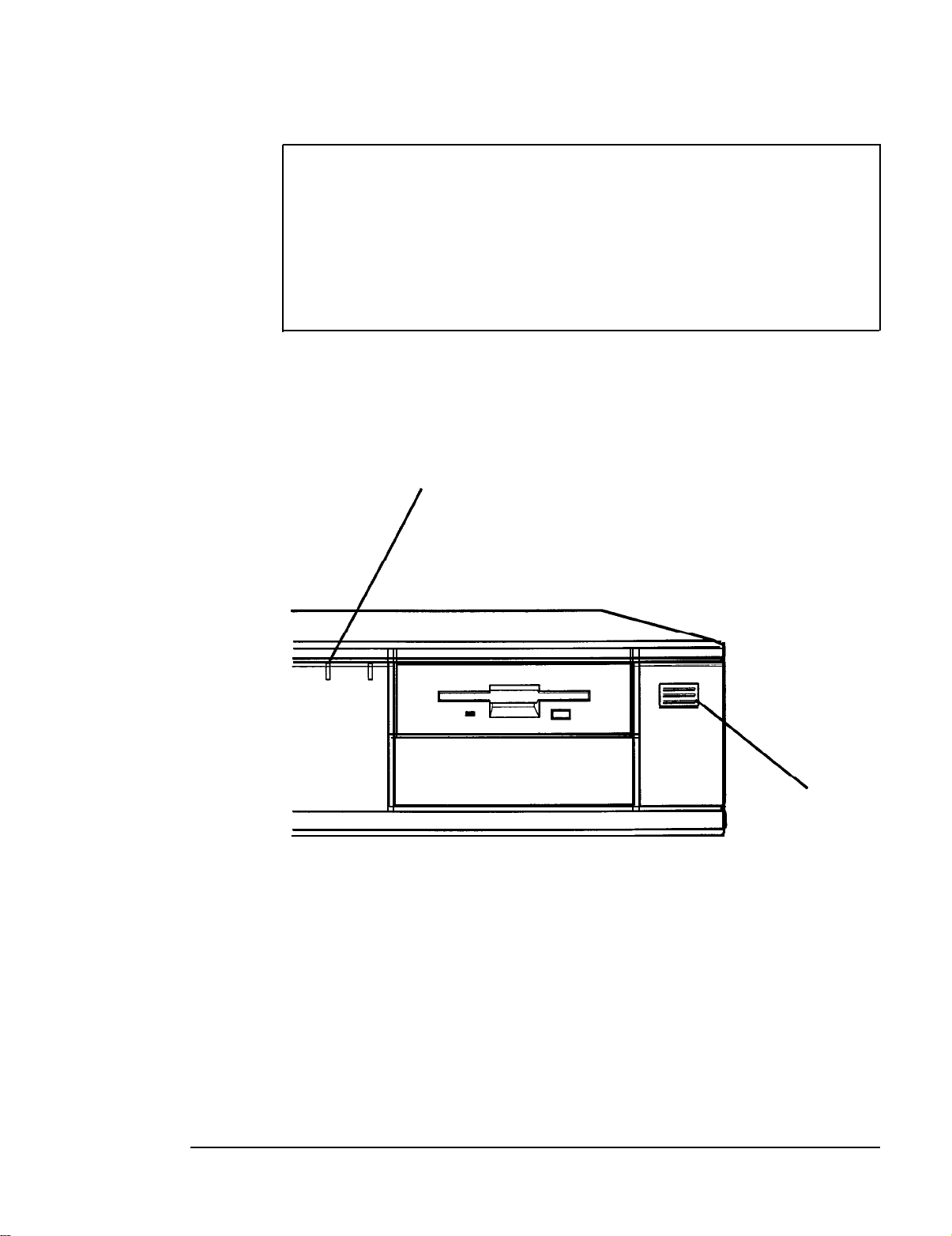
3.
To turn on the computer, press the power button located on
the right side of the front panel, as shown below.
power (SPEED) indicator
power
button
The power indicator lights up. After a few seconds, the
computer displays a count of its system memory, and then
performs its power-on diagnostics. This is a series of checks the
computer runs each time you turn it on to make sure
everything is working correctly. (If necessary, use the controls
on your monitor to adjust the screen display.)
Using Your Computer
1-3
Page 20
If you have made a major change to your system, such as
adding a disk drive, the computer may take a few minutes to
complete power-on diagnostics the first time you turn it on.
When the system has successfully completed its diagnostics,
you see the following prompt:
Press Del to start SETUP
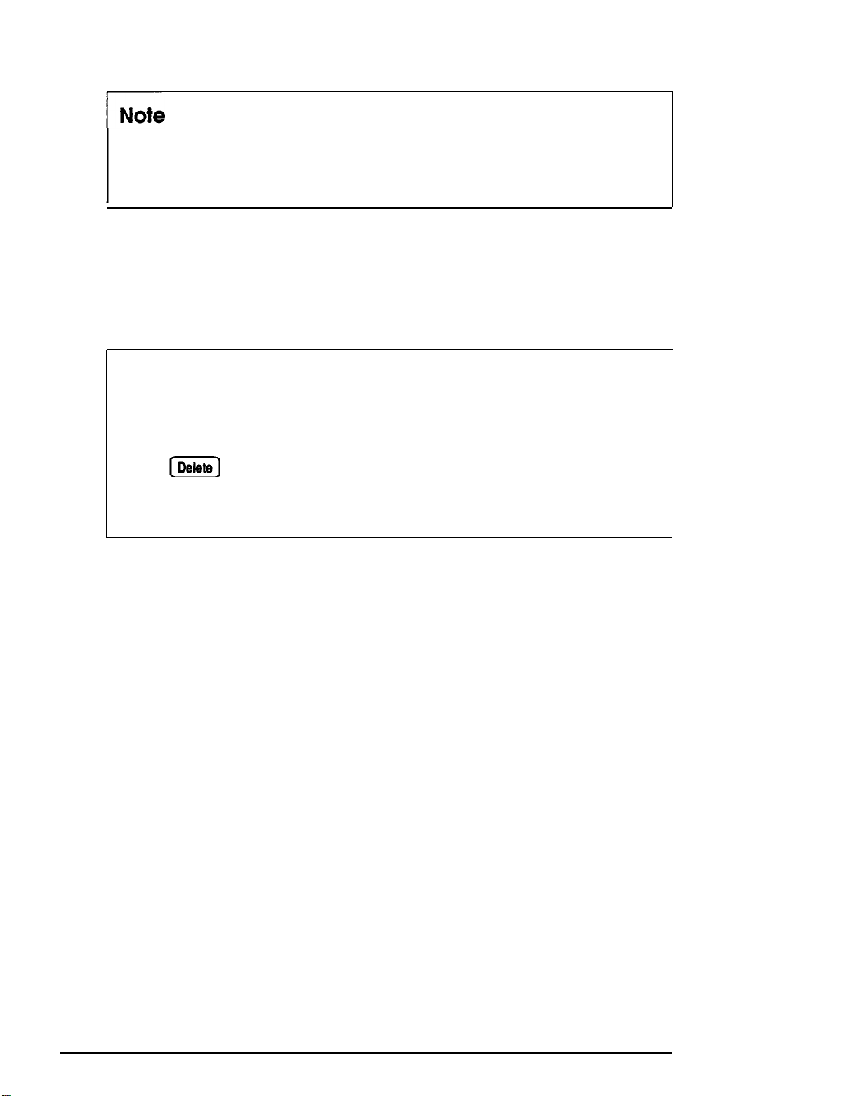
Note
If your computer’s configuration does not match the
information stored in the computer’s CMOS RAM (defined
through the SETUP program), you see an error message.
Press
information. (See Chapter 2 of the
instructions.)
[Delete)
to run the SETUP program to correct the
Setup Guide
for
If you do not want to run SETUP, do nothing. After about five
seconds your computer either loads the operating system from
the hard disk or the diskette in drive A or, if you’ve set a
System Access password, it prompts you for your password.
When you enter the correct password, your computer loads the
operating system.
What happens next depends on how your computer is set up.
If your system is configured to automatically load a program
(such as Microsoft@ Windows@ or a word processing program),
you see the first menu or screen display of that program. If not,
you may see the operating system prompt, such as C : \> or A>.
See your application program manuals for further instructions.
l-4
Using Your Computer
Page 21

Turning Off the Computer
Whenever you turn off your system, follow these steps:
Save your data and exit any application program you are
1.
using.
Check the hard disk drive light and the diskette drive light(s)
2.
to make sure they are not on. Do not turn off the computer
if a drive light is on, because you can damage the drive or
lose data.
Remove any diskette(s) from the diskette drive(s).
3.
Press the power button to turn off the computer and then
4.
turn off any peripheral devices (monitor, printer, etc.).
Using Disks and Disk Drives
The disk drives in your computer allow you to store data on
disk, and then retrieve and use your stored data. This section
explains how disks work and tells you how to:
Use different types of diskettes and diskette drives
Cl
Care for your diskettes and diskette drives
Cl
0
Write-protect diskettes
Insert and remove diskettes
Cl
Use a single diskette drive system
Q
Q
Format diskettes
Make backup copies
0
Use a hard disk drive.
Q
Using Your Computer
1-5
Page 22
How Disks Store Data
Diskettes are made of flexible plastic coated with magnetic
material. This plastic is enclosed in a square jacket that is either
hard (M-inch diskette) or slightly flexible (5.25-inch diskette).
Unlike a diskette, a hard disk is rigid and fixed in place. It is
sealed in a protective case to keep it free of dust and dirt. A
hard disk stores data the same way that a diskette does, but it
works much faster and has a much larger storage capacity.
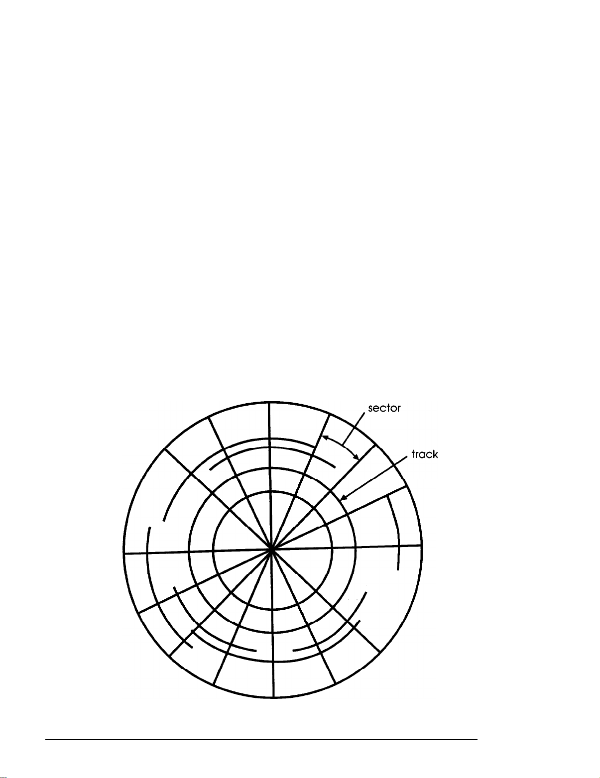
All disks are divided into data storage compartments by sides,
tracks, and sectors. Double-sided diskettes store data on both
sides. On each side are concentric rings, called tracks, on which
a disk can store data.
A disk is further divided by sectors, which can be visualized as
pie slices. The illustration below provides a simple
representation of tracks and sectors.
1-6
Using Your Computer
Page 23

Double-sided and high-density diskettes have 80 tracks on each
side and double-sided, double-density diskettes have either 40
or 80 tracks on each side. Diskettes can have 8, 9, 15, or 18
sectors per track.
A hard disk consists of two or more platters stacked on top of
one another and thus has four or more sides. In addition, a hard
disk has many more tracks per side than a diskette, but the
number of tracks depends on the capacity of the hard disk. The
number of sectors depends on the type of hard disk.
Your computer uses the read/write heads in a disk drive to
store and retrieve data on a disk. To write to a disk, the
computer spins it to the position under the read/write head
where the data is to be written. A diskette has an exposed area
where the read/write head can access it.
Because data is stored magnetically, you can retrieve it, record
over it, and erase it just as you play, record, and erase music on
a cassette tape.
Types of Diskette Drives
The following list describes the types of diskette drives you can
use in your computer and which diskettes to use with them:
0
1.44MB drive-Use 3.5-inch, double-sided, high-density,
135 TPI, 144MB diskettes. These diskettes contain 80 tracks
per side, 18 sectors per track, and hold up to 1.44MB of
information (approximately 600 pages of text).
Note
MB stands for megabyte, which equals 1024KB (or
1,048,576 bytes). KB stands for kilobyte, which equals
1024 bytes. Each byte represents a single character, such
as A, $, or 3.
Using Your Computer
1-7
Page 24
1.2MB drive-Use 5.25-inch, double-sided, high-density,
96 TPI, 1.2MB diskettes. These diskettes contain 80 tracks
per side, 15 sectors per track, and hold up to 1.2MB of
information (approximately 500 pages of text).
720KB drive-Use 3.5-inch, double-sided, double-density,
135 TPI, 720KB diskettes. These diskettes contain 80 tracks
per side, 9 sectors per track, and hold up to 720KB of
information (approximately 300 pages of text).
360KB drive-Use 5.25-inch, double-sided, double-density,
48 TPI, 360KB diskettes. (You can also use single-sided,
160KB or 180KB diskettes.) These diskettes contain 40
tracks per side and 8 or 9 sectors per track. With 8 sectors
per track, a diskette holds up to 320KB. With 9 sectors per
track, a diskette holds up to 360KB of information
(approximately 150 pages of text).
Note
You must format a new diskette before you can store data on
it. See “Formatting Diskettes,” later in this section.
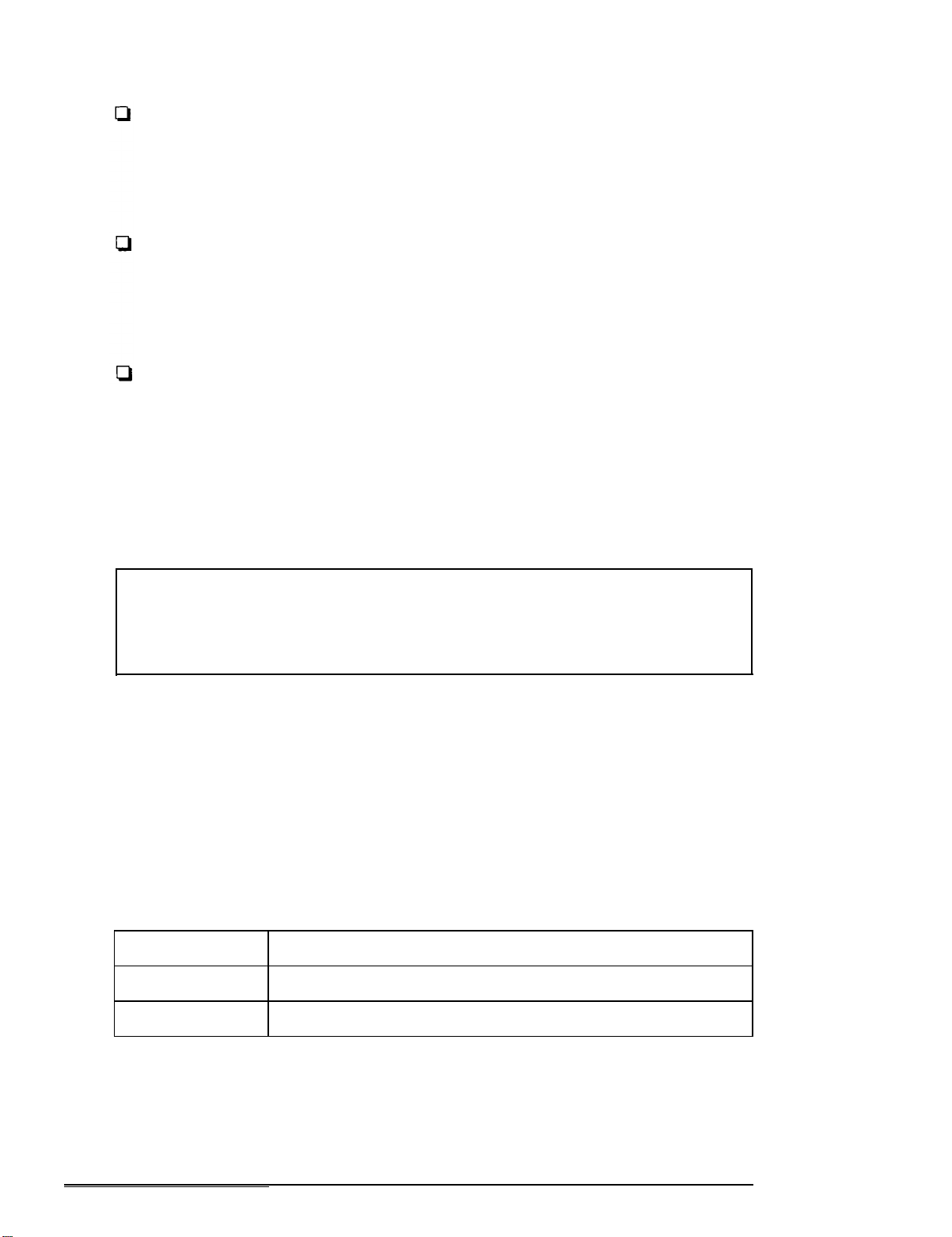
Drive and diskette incompatibilities
If your computer has more than one type of diskette drive, or if
you use different types of diskettes, you need to be aware of
certain incompatibilities between the drives and diskettes. See
the following tables.
3.5-inch drive/diskette compatibility
Drive type
720KB
1.44MB
Diskette types it can read from and write to
720KB
1.44MB. 720KB
1-8
Using Your Computer
Page 25
5.25-inch drive/diskette compatibility
If you write to this diskette in a 1.2MB drive, you may not be able to read it
or write to it in a 360KB drive later.
Because of possible incompatibilities, always indicate the
diskette type and density when you label your diskettes.
(Usually this information appears on the manufacturer’s label.)
Note
If you want to format a 720KB diskette in a l&MB drive or a
360KB diskette in a 1.2MB drive, make sure you include the
correct parameter in your format command. See your
operating system manual for instructions.
If you have any combination of the above drives (1 &MB,
1.2MB, 720KB, or 360KB) and you are using MS-DOS, you can
copy files from one drive to another-using COPY or
XCOPY-as long as the correct diskette type is in each drive.
You can also use these commands to copy files between a hard
disk and any type of diskette. However, you cannot use the
MS-DOS DISKCOPY command to copy from one diskette drive
to another if the two drives are not the same type. For more
information, see your operating system manuals.
Using Your Computer
1-9
Page 26
Caring for Diskettes and Diskette Drives
Follow these basic precautions to protect your diskettes and
avoid losing data:
0
Remove all diskettes before you turn off the computer.
If you have a diskette that contains data you
don’t want to accidentally write over or erase,
be sure you write-protect it. This is especially
important for your operating system and
application program diskettes. See “Writeprotecting Diskettes,” below, for more details.
Cl
Do not remove a diskette from the diskette drive or reset or
turn off the computer while the drive light is on. This light
indicates that the computer is copying data to or from a
diskette. If you interrupt this process, you can destroy data.
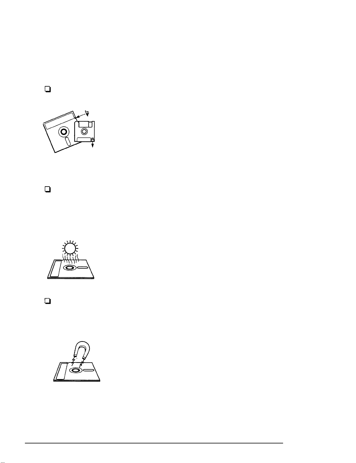
Keep diskettes in a moderate environment.
Don’t leave them sitting in the sun or in
extreme cold or heat because this can destroy
the data.
Q
Keep diskettes away from dust and dirt. Small particles of
dust or dirt can scratch the magnetic surface, destroy data,
and ruin the read/write heads in a diskette drive.
Keep diskettes away from magnetic fields,
such as those generated by electrical
appliances, telephones, and loudspeakers.
(Diskettes store information magnetically.)
l-10
Using Your Computer
Page 27
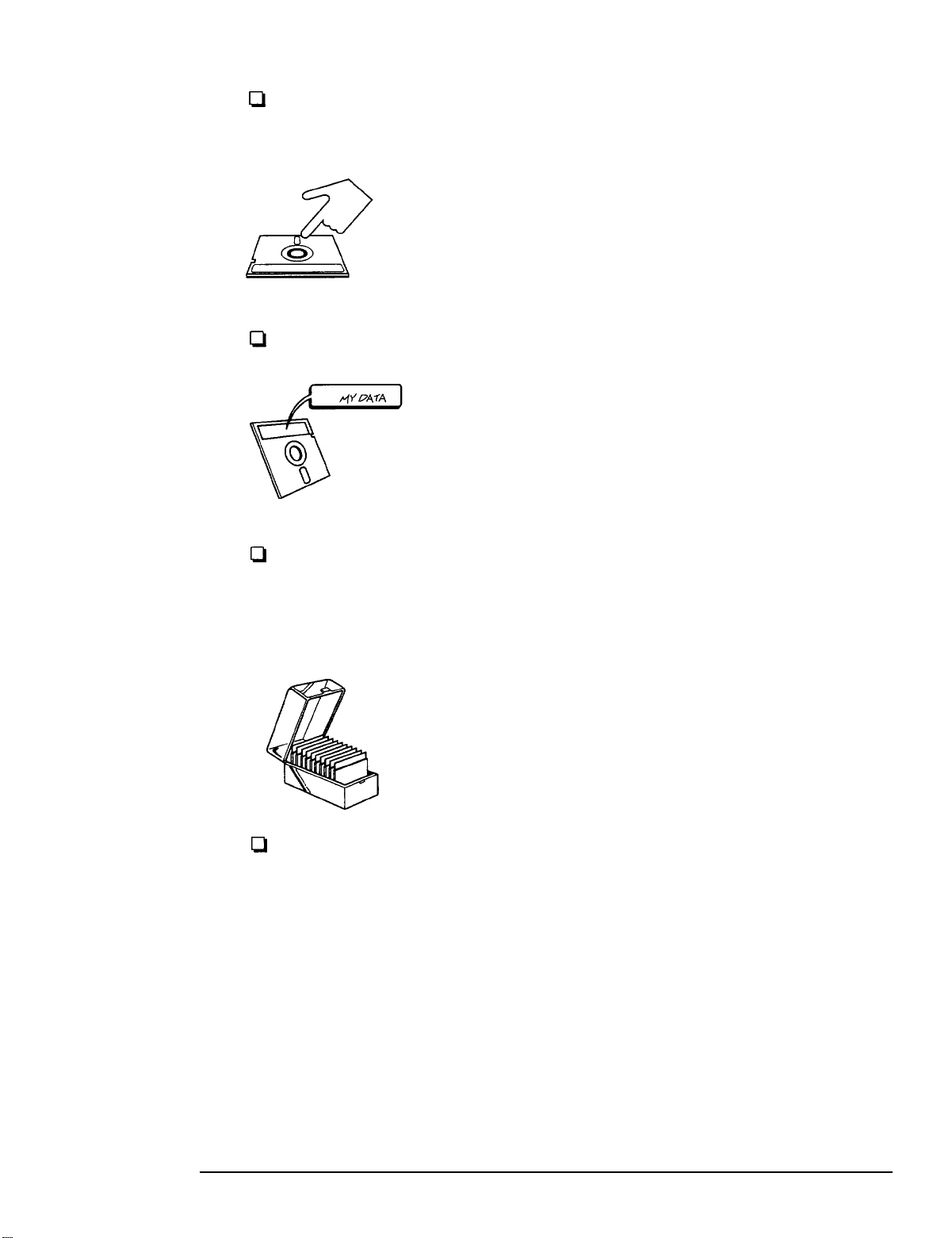
CI
Do not place diskettes on top of your monitor or near an
external hard disk drive.
Always hold a 5.25-inch diskette by its
protective jacket and never touch the magnetic
surface (exposed by the read/write slot). The
oils on your fingertips can damage it.
Q
Never wipe, brush, or try to clean diskettes in any way.
Write on a diskette label before you attach it to
the diskette. If you need to write on a label that
is already on the diskette, use only a soft-tip
pen-not a ballpoint pen or a pencil.
0
Carefully label your diskettes and indicate the type and
density. Do not stick several labels on top of one another;
this can make it difficult to insert and remove the diskette
in the drive.
Store diskettes in their protective envelopes and
in a proper location, such as a diskette container.
Do not store diskettes flat or stack them on top of
each other.
CI
Do not place anything on top of your diskettes, and be sure
they do not get bent.
Using Your Computer
l-11
Page 28
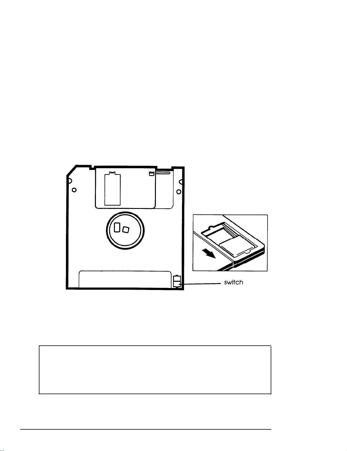
Write-protecting Diskettes
You can write-protect a diskette to prevent its data from being
altered. When a diskette is write-protected, you can read it and
copy data from it, but you cannot store new data on it or delete
any files it contains.
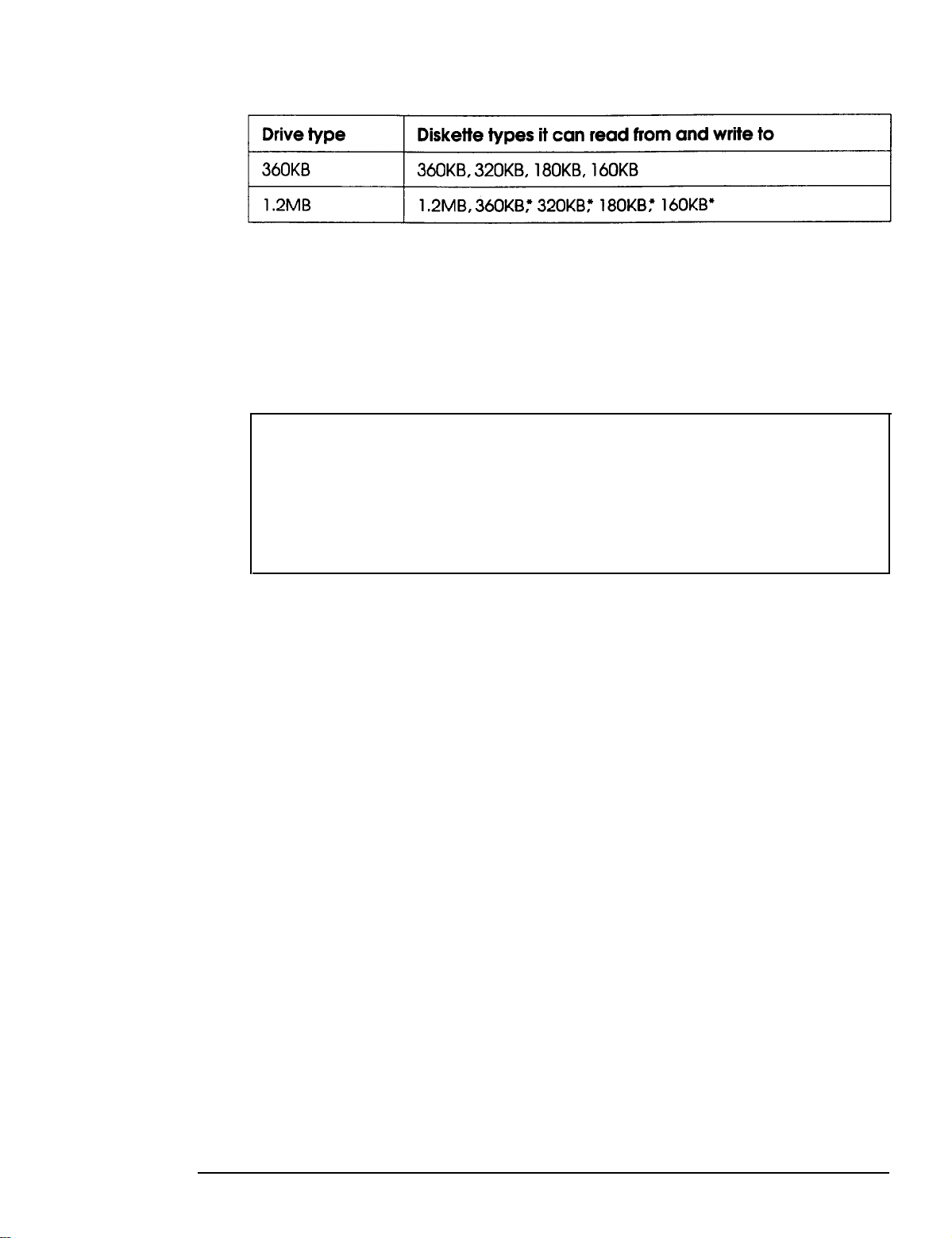
On a 3.5-inch diskette, the write-protect device is a small switch
on the back of the diskette in the lower right comer, shown
below. To write-protect a 3.5-inch diskette, slide the switch
toward the edge of the diskette until it clicks into position,
exposing a hole in the comer.
1-12
To remove the write protection, slide the switch toward the
center of the diskette until it clicks into position and the hole is
covered.
Note
A high-density 3.5-inch diskette has an additional hole on
the opposite side. This hole does not affect the writeprotection.
Using Your Computer
Page 29
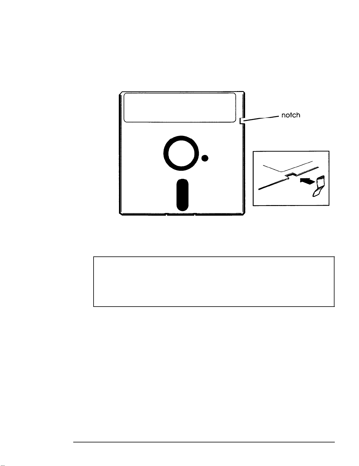
To write-protect a 5.25-inch diskette, cover the small,
rectangular notch (shown below) with an adhesive
write-protect tab. Write-protect tabs usually are included in a
new package of blank 5.25-inch diskettes.
To remove the write protection, peel off the write-protect tab.
Note
Some program diskettes have no switch or notch so they are
permanently write-protected. This protects them from being
accidentally erased or altered.
Using Your Computer
1-13
Page 30
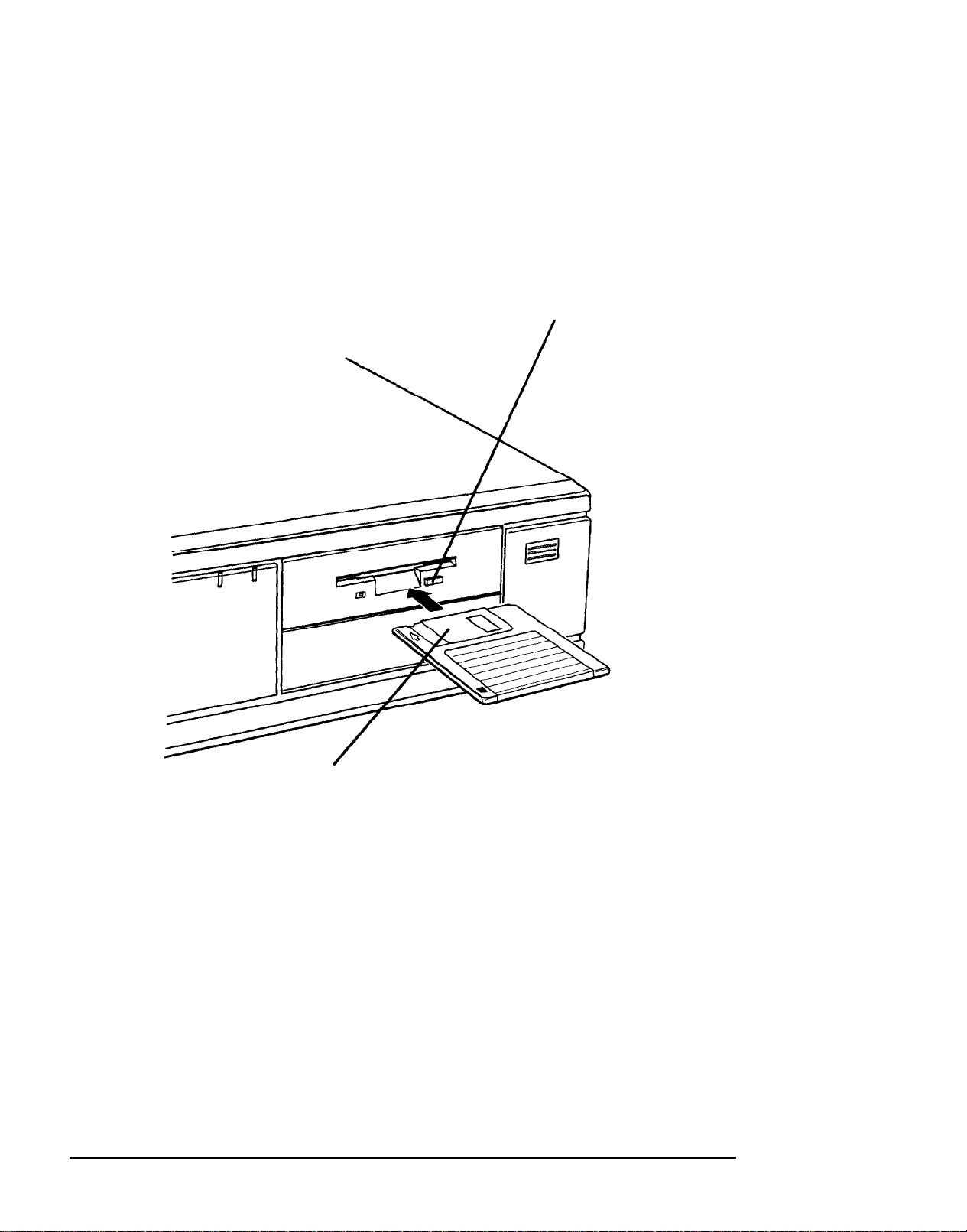
inserting and Removing Diskettes
To insert a diskette into a 3.5-inch drive, hold the diskette with
the label facing up and the metal shutter leading into the drive
as shown in the following illustration. Slide the diskette into the
drive until it clicks into place.
release button
1-14
metal shutter
When you want to remove the diskette, make sure the drive
light is off; then press the release button. When the diskette
pops out, remove it and store it properly.
Using Your Computer
Page 31

To insert a diskette into a 5.25-inch drive, hold the diskette with
the label facing up and the read/write slot leading into the
drive, as shown below.
latch
read/write
slot
Slide the diskette all the way into the slot. Then turn the latch
down to lock it in a vertical position. This keeps the diskette in
place and enables the read/write heads to access the diskette.
Note
Some 5.25-inch drives have a release button rather than a
latch.
I
I
When you want to remove a diskette, first make sure the disk
drive light is off. Then flip up the latch and carefully pull out
the diskette. Place it in its protective envelope and store it in a
proper location, such as a diskette container.
Using Your Computer
1-15
Page 32

Caution
Never remove a diskette or reset or turn off the computer
while a diskette drive light is on. You could lose data. Also,
remove all diskettes before you turn off the computer.
Using a Single Diskette Drive System
Most operating systems expect the computer to have at least
two diskette drives and display prompts and messages
accordingly. MS-DOS, for example, recognizes the first diskette
drive (the top drive) as drive A and a second diskette drive as
drive B. If you have only one diskette drive, MS-DOS can treat
it as both A and B when you need to perform operations that
normally would use two diskette drives.
For example, if you enter a command to copy data from A to B,
MS-DOS copies the data from the first diskette you place in the
drive (which would be drive A) to the computer’s memory.
Then MS-DOS prompts you to insert another diskette (for
drive B) and copies the data from memory to the new diskette.
When copying is complete, you see a prompt to insert the
original diskette (A).
Because you may often swap diskettes this way, it is important
to remember which diskette is which. It is also a good idea to
write-protect your original diskette. (See “Write-protecting
Diskettes,” above.)
If you have a hard disk and one diskette drive, you can load the
operating system and application programs from the hard disk,
create and store your data there, and use the diskette drive just
for copying data to or from diskettes.
1-16
Using Your Computer
Page 33

However, if you have only one diskette drive and no hard disk,
you need to use that drive to load the operating system as well
as any application program you are using. First, insert the
operating system diskette in drive A and load the operating
system; this copies it to the computer’s memory (RAM) so
do not need to leave the system diskette in the drive. Then
remove the system diskette and insert your application
program diskette to load that data into memory, too. See your
application program manual for detailed instructions.
Formatting Diskettes
Before you can store data on a new diskette, you must format it.
Formatting prepares the diskette so that the operating system
can write data on it. You need to do this only once, before you
use the diskette for the first time.
You can also reformat previously used diskettes to store new
data. This process erases all the data on the diskette, so be sure
you do not want to save any of the files on a used diskette
before you format it. See your operating system manual for
instructions on formatting diskettes.
you
Making
It is important to make copies of all your data and system
diskettes. Make backup (or working) copies of all diskettes that
contain programs, such as your operating system, Reference,
and Utility diskettes; then use only the copies. Store the original
diskettes away from your working diskettes. Also, copy your
data diskettes regularly, whenever you revise them, and store
them away from your originals.
If you have a hard disk, you’ll probably use it to store the
programs and data files you use regularly. Keep backup copies
of all your files on diskettes or tapes (if you have a tape backup
drive).
Backup Copies
Using Your Computer
l-17
Page 34

Using a Hard Disk Drive
Using a hard disk is similar to using a diskette. However, the
hard disk provides several advantages:
An 80MB hard disk can store as much data as
approximately sixty-six 1.2MB diskettes or fifty-five 1.44MB
diskettes, and a 120MB hard disk can store about a third
more. A 240MB hard disk can store the equivalent of two
hundred 1.2MB diskettes or one hundred sixty-six 1.44MB
diskettes.
Your computer can perform all hard disk operations faster.
You can store frequently used programs and data files on
the hard disk, eliminating the inconvenience of swapping
diskettes to access different files.
The added storage capacity makes it easy to move back and
forth between different programs and data files. However,
because it is so easy to add programs and files to your hard
disk, you may find yourself trying to organize hundreds of files.
Most operating systems let you keep related files together in
directories and subdirectories so they are easy to find and use.
See your operating system manual for instructions on
managing your files and directories.
Note
A hard disk must be partitioned and formatted before you
can use it. Be sure you have performed the procedures
described in your operating system manual to prepare your
hard disk for use.
1-18
Using Your Computer
Page 35

Backing up the hard disk
While the hard disk is very reliable, it is essential to back up
your hard disk files to diskettes or tapes in case you lose some
data accidentally. Make copies of all your system and
application program diskettes before copying the programs to
the hard disk. After you create data files on the hard disk, be
sure to copy them whenever you revise them to keep your
backup diskettes or tapes up-to-date.
Caring for your
Follow these precautions to protect your hard disk drive from
damage and to avoid losing data:
Never turn off or reset the computer when the hard disk
access light is on. This light indicates that the computer is
copying data to or from the hard disk. If you interrupt this
process, you can lose data.
Never attempt to open the hard disk drive. The disk itself is
enclosed in a sealed container to protect it from dust.
If you need to move your computer, you may need to run
the HDSIT program to prepare the hard disk for moving, as
described on page
hard
disk
1-26.
Using Your Computer
1-19
Page 36

Special Keys on the Keyboard
Certain keys on your keyboard serve special functions when
your computer is running your operating system or application
programs, as described in the table below.
Special key functions
1-20
Using Your Computer
Page 37

Special key functions (continued)
Key
Purpose
1
[-)-IF12
I-
@bid (Req)
[scmw
Ipause)
m
The
(PrtSc) Prints the screen display on a printer.
[G),
and
Perform special functions within application
programs.
Generates the System Request function in some
application programs (used with [).
Controls scrolling in some applications.
Suspends the current operation.
Stops the current operation (used with [Cm]>.
[krdl]
keys work as toggles; press
the key once to turn on a function and again to turn it off. When
the function is enabled, the corresponding light in the upper
right corner of the keyboard is on.
Stopping a Command or Program
You may sometimes need to stop a command or program while
it is running. If you have entered an MS-DOS or application
program command that you want to stop, try one of the
following:
Cl
Press
Q
Hold down the
0
Hold down the
[Pause]
[T]
[w]
key and press
key and press
[c1
[WI.
If these methods do not work, you may need to reset the
computer as described below. Do not turn off the computer to
exit a program or stop a command unless you have to, because
the computer erases any data you did not save.
Using Your Computer
1-21
Page 38

Resetting the Computer
Occasionally, you may want to clear the computer’s current
settings or its memory without turning it off. You can do this
by resetting the computer.
For example, if an error occurs and the computer does not
respond to your keyboard entries, you can reset it to reload
your operating system and try again. However, resetting erases
any data in memory that you have not saved; so reset only if
necessary.
Caution
Do not reset the computer to exit a program. Some programs
classify and store new data when you exit them in the
normal manner. If you reset the computer without properly
exiting a program, you may lose data.
To reset the computer, the operating system must be either on
the hard disk or on a diskette in drive A; so if you do not have a
hard disk, insert the system diskette in drive A. If you are using
MS-DOS, hold down
screen goes blank for a moment and then the computer should
reload your operating system.
If resetting the computer does not correct the problem, you
probably need to turn it off and reboot it. Remove any
diskette(s) from the diskette drive(s). Turn off the computer
and wait 20 seconds. If you do not have a hard disk, insert the
system diskette in drive A. Then turn on the computer.
(T)
and
(71
and press
IBlete_].
The
1-22
Using Your Computer
Page 39

Using a
If you set a System Access password when you ran the SETUP
program, you must enter it every time you turn on or reset the
computer. Follow these steps to use your password:
1.
If you do not have a hard disk, insert your system diskette
in drive A.
2.
Turn on or reset the computer. You see the following prompt:
3.
Type your password. You see an asterisk for each character
Password
Enter Password:
you type. Then press
After you type the password correctly and press
computer loads the operating system and displays the
command prompt.
Note
If you do not know the correct password, see “Password
Problems” in Chapter 6.
[Enter].
Changing or Deleting a Password
To change or delete your password, you must run the SETUP
program and follow the instructions for entering a password in
Chapter 2 of the
If you do not know your password, see “Password Problems”
in Chapter 6.
Setup Guide.
[=I,
the
Using Your Computer
1-23
Page 40

Changing the Processor Speed
Your computer’s processor can operate at two speeds: high
or low. High speed is the highest speed at which your
microprocessor is capable of running, such as 25,33, or
50 MHz. Low speed simulates an 8 MHz processor to provide
compatibility with older application programs.
Note
When your computer is operating at high speed, the
light on the front panel is green. When the computer is
operating at low speed, the light is amber.
You should use high speed for almost everything you do
because your programs will work faster. However, certain
application programs have specific timing requirements and
can run only at the slower speed. See your software manual to
determine if this is the case.
SPEED
Some copy-protected programs require the computer to run at
low speed while accessing the program on a diskette. These
programs also usually require you to leave a key disk—the
diskette that contains the copy protection-in the diskette
drive. If you use a copy-protected program, you can change the
speed to low to access the diskette and return it to high speed
when you are finished.
1-24
Using Your Computer
Page 41

You can change the processor speed temporarily by entering
one of the following commands from the numeric keypad on
your keyboard:
Ll
To select low speed, press
Ll
To select high speed, press
[‘)(~)[-I.
[ctrf) [r)m.
(Hold down the
and then press the m or
[F)
key and the
I-1
key on the numeric keypad.)
[T)
key simultaneously
The speed setting remains in effect until you do the following:
Ll
Press
[ctll] [rut)
(Delete)
Cl
Turn off the computer
CI
Change it with another keyboard command.
Using Your Computer
1-25
Page 42

Preparing the Hard Disk for Moving
If you need to move your computer to a new location, you may
want to run the HDSIT program provided on your Reference
diskette to protect the hard disk during the move.
HDSIT moves (or parks) the disk drive’s read/write heads to a
region on the disk surface that does not contain data, and locks
them securely in position. This protects the hard disk from
being damaged if the computer is bumped accidentally.
Many hard disk drives, including all Epson drives,
automatically park their heads when you turn off the computer.
If your hard disk drive does not do this, or if you are not sure
that it does, be sure to run HDSIT.
If you have not already done so, copy the HDSIT.COM and
HDSIT.VER files from the Reference diskette to the root
directory on your hard disk. Then, when you want to run
HDSIT, type HDSIT and press
[G).
You see a message on the screen that tells you the disk drive’s
read/write heads will remain locked until you reset the
computer or turn the power off and on again. The computer
then locks the heads and disables the keyboard. Remove any
diskettes and turn off the computer. Now you can move it to
the new location.
Caution
Whether you use HDSIT or not, always turn off your
computer and wait at least 20 seconds before you move it.
This allows your hard disk drive’s read/write heads to move
away from the disk to a safe location. If you move your
computer before this happens, you could damage your hard
disk drive.
1-26
Using Your Computer
Page 43

Using AUTOEXEC.BAT and Other Batch files
If you are using MS-DOS to access your application programs,
you may find that there are commands you need to run
frequently. You can automate the execution of these commands
by listing them in a special file called a
type the name of the batch file and press
executes the commands in the file just as if you had typed each
command from the keyboard.
If you have a word processing program that can save a file as a
text-only file (sometimes called an ASCII file), you can use it to
create a batch file. You can also use the MS-DOS COPY, EDIT,
or EDLIN command, or a text editor, to create the file.
One batch file that you may find particularly useful is called
AUTOEXEC.BAT. Every time you turn on your computer,
MS-DOS looks for the AUTOEXEC.BAT file and automatically
executes each of the commands in the file.
When you install MS-DOS, it creates an AUTOEXEC.BAT file
for you, which you can modify or replace as described above.
Be sure to name the file AUTOEXEC.BAT and store it in the
root directory of the hard disk or diskette from which you load
batch file.
[=I,
MS-DOS
When you
MS-DOS. (You may want to rename your original file to
AUTOEXEC.OLD, in case you need to use it again later.)
See your MS-DOS documentation for more information about
creating and using batch files.
Using Your Computer
1-27
Page 44

Chapter 2
Installing and Removing Options
You can enhance the performance of your computer by adding
optional equipment such as memory modules, option cards, or
an Intel OverDrive processor.
Memory modulesmodules)-allow you to increase the amount of memory in
your computer.
An option card is a circuit board you install in your computer
to add a particular function, such as a modem or an additional
interface port.
An OverDrive processor is a CPU chip which doubles the
internal processing speed of the microprocessor and includes a
built-in math coprocessor. If you have the 486SX/25 or
486DX/33 system, you can install an OverDrive processor on
your system board to provide this increased performance.
(Alternatively, on the 4865X/25 system you can install a
487SX/25
chip to provide math coprocessor support.)
also called SIMMs (single inline memory
Installing and Removing Options
2-1
Page 45

How to Use This Chapter
This chapter explains how to do the following:
Ll
Remove the computer’s cover
Ll
Change jumper settings on the main system board
0
Install (and remove) memory modules (SIMMs)
cl
Install an option card
Ll
Remove an option card
Ll
Remove the option card connector board (to access the
main system board)
0
Replace the option card connector board
0
Install a new processor chip (CPU)
CL
Increase the video memory
Ll
Use the alternate VGA interface (feature connector)
CL
Use a display adapter card
Ll
Replace the cover.
Follow the steps in the first section to remove the cover, and
then go to the appropriate section for the instructions you need.
When you finish, see the instructions at the end of this chapter
to replace the computer’s cover.
2-2
Installing and Removing Options
Page 46

Locating the lnternal Components
As you follow the instructions in this chapter, refer to the
following illustration to locate the different components inside
your computer.
Installing and Removing Options
2-3
Page 47

Removing the Cover
You need to remove the computer’s cover to install any of the
options described in this chapter or to install or remove a disk
drive (as described in Chapter 3). Follow these steps:
1.
Turn off the computer and then any peripheral devices
(including the monitor and printer).
2.
Disconnect the computer’s power cable from the electrical
outlet and from the back panel. Also disconnect any cables
that are connected to the computer, including the keyboard
and mouse cables.
3.
If the monitor is on top of the computer, lift it off and set it to
one side.
4.
Turn the computer around so the back panel is facing you.
5.
Remove the three screws securing the back panel, as shown
below.
2-4
Installing and Removing Options
Page 48

6.
Turn the computer around again so that the front panel is
facing you.
7.
Grasp the sides of the cover and pull it straight toward you
until it stops, just before it reaches the front of the
computer. Then lift it off at an angle as shown below.
8.
Set the cover aside.
9.
Ground yourself to the computer by touching the metal
surface of the back panel.
WARNING
Be sure to ground yourself by touching the back panel of the
computer every time you remove the cover. If you are not
properly grounded, you could generate an electric shock that
could damage a component when you touch it.
Installing and Removing Options
2-5
Page 49

Changing the Jumper Settings
The main system board in your computer has a number of
jumpers which control certain functions. These jumpers are
preset at the factory to default positions; however, you can alter
the following functions by changing the standard settings:
0
Enable or disable the built-in VGA display adapter
Set the computer to use a CGA or other type of display
0
adapter
0
Reset the CMOS RAM settings to the factory defaults
0
Enable or disable the PQFP (surface-mounted)
microprocessor on some 486SX/25 systems
D
Change the microprocessor type (if you upgrade your
system with a new microprocessor)
0
Change the processor speed.
If you need to change any jumper settings, or if you want to
check the current settings, follow the instructions in this section.
The following tables list the jumper settings and their functions.
2-6
Installing and Removing Options
Page 50

Adapter, CMOS, and PQFP jumper settings
l Factory setting
l
*
Two pin jumpers
Processor jumper settings
You need to change the processor jumper settings when you
upgrade your system by installing a new processor chip. Make
sure the jumper settings for J10, Jll, and J12 correspond to the
type of chip you installed.
Installing and Removing Options
2-7
Page 51

Note
If the microprocessor in your system is a PQFP type, it is
surface-mounted on the main system board. This means that
if you install an OverDrive processor, you can install it in the
empty OverDrive socket. In this case, you need to disable the
original microprocessor by moving jumper J23 to position
2-3. You also need to make sure the jumper settings for Jl0,
Jll, and J12 are set correctly.
Processor speed jumper settings
You need to change the processor speed jumper settings only if
you replace a 25 MHz processor with a 33 MHz processor.
2-8
Installing and Removing Options
Page 52

Setting the Jumpers
If you need to change any jumper settings, follow these steps:
1.
Refer to the illustration below to locate the jumpers.
2.
If there are any option cards installed in your computer, you
need to remove them to access the jumpers. See page 2-20.
3.
If the option card connector board is in your way, you can
remove it. See page 2-21 for instructions.
Installing and Removing Options
2-9
Page 53

4.
A jumper’s setting is determined by where the jumper is
placed on the pins. A two pin jumper either connects both
pins (on) or sits on just one of the pins (off), as illustrated
below.
ON
OFF
For three pm jumpers, the jumper connects pin 1 and the
middle pin (position l-2) or pin 3 and the middle pin
(position 2-3), as shown below.
(In the off position, a three pin jumper sits on only one of the
end pins.)
To move a jumper from one position to the other, use
needle-nose pliers or tweezers to pull it off its pins and
gently move it to the desired position.
2-20
Caution
Be careful not to bend the jumper pins or damage any
surrounding components on the main system board.
5.
If you removed the option card connector board, replace it
now. See page 2-22 for instructions.
6.
Replace any option cards you removed. See page 2-16 for
instructions.
Installing and Removing Options
Page 54

Memory Modules (SIMMs)
Your computer comes with 4MB of memory installed in a
SIMM socket. By installing memory modules-also called
SIMMs (single inline memory modules)-you can increase the
amount of memory in your computer up to 32MB.
There are two SIMM sockets on the main system board, and
each can contain one memory module. You can install SIMMs
with a capacity of lMB, 4MB, or 16MB.
The following table shows the possible SIMM configurations;
do not install memory in any other configuration.
SIMM configurations
Installing and Removing Options
2-11
Page 55

Before you install SIMMs, check the following guidelines to
ensure that they will work properly:
Use only 36-bit, fast-page mode SIMMs that operate at an
access speed of 70ns (nanoseconds) or faster. Be sure all the
SIMMs operate at the same speed.
Use the correct SIMM configuration to add the amount of
memory you want. See the table above.
Your computer can use any SIMM that complies with
industry standards; however, it is best to use Epson SIMM
option kits to ensure reliability and compatibility.
Once you have the SIMMs you need, you can install them in
your computer. Follow the instructions below.
2-12
Installing and Removing Options
Page 56

Inserting SIMMs
Follow these steps to install SWIMS:
1.
Refer to the illustration on page 2-3 to locate the SIMM
sockets near the front of the computer.
2.
Remove any option cards that may be blocking your access to
the SIMM sockets. See page 2-20 for
3.
Position the SIMM over the socket at an angle, as shown
below. The components on the SIMM should face the
outside of the computer.
instructions.
Installing and Removing Options
2-13
Page 57

4.
Push the SIMM into the socket until it is seated firmly in the
slot. Then tilt it upright, as shown below, guiding the hole
at each end of the SIMM over the retaining post at each end
of the SIMM socket.
2-14
If it does not go in smoothly, do not force it; pull it all the way
out and try again.
5.
Repeat steps 3 and 4 for the second SIMM.
6.
Replace any option cards you removed. See page 2-16 for
instructions.
7.
The next time you turn on your computer, run the SETUP
program so your computer can update its configuration
information with the new memory. See Chapter 2 of the
Setup Guide
Installing and Removing Options
for instructions.
Page 58

Removing SIMMS
If you need to remove SIMMs from your computer (to install
different ones, for example), follow the steps below.
1.
Remove any option cards that may be blocking your access to
the SIMM sockets. See page 2-20 for instructions.
2.
Use your fingers or two small screwdrivers to carefully pull
away the tabs that secure the SIMM at each end. As you
pull away the tabs, the SIMM falls to the side. Remove it
from the socket.
tabs
3.
If necessary, follow the same procedure to remove the other
SIMM.
4.
Replace any option cards you removed. Follow the
instructions below.
Installing and Removing Options
2-15
Page 59

5.
The next time you turn on your computer, run the SETUP
program so your computer can update its memory
configuration.
lnstalling an Option Card
This section explains how to install an option card in your
computer. Your computer has four option slots to
accommodate up to four B-bit or 16-bit option cards.
Usually it does not matter which slot an option card occupies as
long as the card fits in the slot. For example, you can place
some B-bit cards in a 16-bit slot. However, follow these
guidelines when deciding which slot to use:
If you have an B-bit card that has an additional tab along
the bottom, it will not fit in any of the option slots in your
computer.
If you are installing a high-resolution graphics adapter
card, follow the instructions below to install the adapter
card; then see “Using the Alternate VGA Interface” on page
2-26 to connect the card to the VGA feature connector in
your computer.
You may not be able to install a half-length or full-length
option card in the slot closest to the system board (Slot 1).
However, you can install one that is no longer than 110 mm
(4.4
inches).
Note
Before you install an option card, see if you need to change
any jumper settings on the system board. For example, if
you install a video card, you may need to change jumper J5.
See page 2-6.
2-16
Installing and Removing Options
Page 60

Follow these steps to install an option card:
1.
If this is the first time you are installing a card in the option
slot, you need to remove the metal cover for that slot on the
inside back panel. Remove the retaining screw securing the
option slot cover to the computer. (Keep the screw to secure
the option card to the computer.)
cover
2.
Slide out the slot cover and set it aside. (Store the slot cover in
a safe place in case you remove the option card later.)
Installing and Removing Options
2-17
Page 61

3.
Unpack the option card and adjust any switches or jumpers
on it, if necessary. (Check the option card instructions.)
When you handle the card, be careful not to touch any of
the components on the circuit board or the gold-edged
connectors. If you need to set it down before you install it,
place it gently on top of its original packing material with
the component side facing up. Keep the packing materials
in case you remove the card later.
4.
Hold the card along the top comers and guide it into the
connector, as shown below. (If you’re installing a
full-length card, insert the front edge of the card into the
corresponding guide inside the computer’s front panel.)
2-18
Installing and Removing Options
Page 62

Once the connectors reach the slot, push the card in firmly
(but carefully) to insert it fully. You should feel the card fit
into place. If it does not go in smoothly, do not force it; pull
the card all the way out and try again.
5.
Secure the end of the card to the computer with the retaining
screw.
Note
If you installed a high-resolution graphics adapter card, see
“Using the Alternate VGA Interface,” on page 2-26, for
further instructions.
Installing and Removing Options
2-19
Page 63

Removing an Option Curd
You may need to remove an option card installed in your
computer to access components on the main system board-to
change a jumper setting, for example. You may also want to
remove a card if you no longer need it. Follow these steps:
Remove the retaining screw securing the option card to the
1.
computer. Then pull the card straight out of the slot.
2-20
Set the card aside with the component side facing up.
2.
When you are ready to re-install the option card, see page 2-16
for instructions.
Installing and Removing Options
Page 64

Removing the Option Card Connector Board
You may want to remove the option card connector board to
access certain components on the main system board, such as
jumpers or the disk drive controllers. ‘Follow these steps:
1.
Remove any option cards. (See the instructions above.)
2.
Remove the retaining screw securing the bracket on the
option card connector board to the power supply.
3.
Pull the board straight up and out of its socket and set it aside.
Installing and Removing Options
2-21
Page 65

Replacing the
If you removed the option card connector board to access any
system components, follow these steps to replace it:
1.
Position the board above its slot as shown below, and then
firmly push it straight in.
Option Card Connector Board
2-22
2.
Secure the board to the power supply with its retaining screw.
Now you can re-install any option cards you removed. See
page 2-16 for instructions.
Installing and Removing Options
Page 66

lnstalling a
If you have a 486SX/25 or 486DX/33 system, you can enhance
your system’s performance by installing an Intel OverDrive
processor. Alternatively, for the 486SX/25, you can install a
487SX/25 microprocessor with built-in math coprocessor.
Complete instructions for installing the processor are provided
in the manual that comes with it. Please follow those
instructions carefully, along with the following guidelines:
Although the OverDrive processor User’s Guide instructs
you to remove the main system board from the computer,
this is not necessary. You can leave the board inside the
computer case while you install the processor.
Refer to the illustration on page 2-3 to locate the
microprocessor socket on the system board. If this socket is
empty, you can install the OverDrive processor (or 487SX
chip) directly in the socket. If it contains the CPU chip, you
New Processor Chip
need to remove it before you install the new processor.
If you need to remove the existing microprocessor, lift the
lever to release the CPU chip. After you install the new
processor, push the lever down to secure it in the socket.
If you install an OverDrive processor or the 487SX/25 chip,
you may need to change the settings of the jumpers J10
through J12, as described on page 2-7. If you install the
OverDrive processor in an empty socket, you need to
change the jumper setting of J23 to position 2-3 as well.
After you install the processor and replace the computer’s
cover, run the SETUP program so your computer can
update its configuration. See Chapter 2 of the
for instructions. (You need only run the program and save
the configuration; you do not need to change any settings.)
Setup Guide
Installing and Removing Options
2-23
Page 67

lncreasing
Your computer comes with 512KB or 1MB of video memory. If
you have 512KB, you can increase your video memory to 1MB
by installing four video DRAM, 20-pin, DIP (Dual Inline
Package) chips. This is useful for running graphics-intensive
applications or for supporting resolutions up to 1024 x 768 on
your monitor.
The following table lists which video DRAM DIP parts you can
install on the main system board.
Supported video DRAM chips
the Video Memory
Installing the Memory Chips
You need four memory chips to install the optional memory.
For the memory to work properly, you must install one chip in
each of the four empty video memory sockets on the system
board. To install the chips you’ll need a chip puller or a small,
flat-head screwdriver. Follow these steps:
1.
Locate the memory chip sockets on the main system board,
shown on page 2-3. The chip sockets you’ll use are the
empty ones, numbered M5 through MB.
2-24
Installing and Removing Options
Page 68

2.
If there is an option card in your way, remove it. See
page 2-20 for instructions.
Caution
To avoid generating static electricity and damaging the
memory chips, ground yourself by touching the metal
surface on the inside of the computer’s back panel. Then
remain as stationary as possible while you install them.
3.
Remove the memory chips from their package and inspect
each one. The pins should point inward at slightly less than
a 90o angle.
If any of the pins are bent, straighten them gently with your
fingers or with small tweezers to align them with the other
pins. Be careful when you do this; the pins are fragile and
can break off easily.
4.
Position one of the memory chips over the first socket as
shown below, aligning the pins on the chip with the holes
in the socket. Make sure the small notch on the end of the
chip is toward the filled row of memory chips.
Installing and Removing Options
2-25
Page 69

5.
Gently press the chip halfway into the socket (to make sure it
is correctly aligned). If the chip goes in at an angle, remove
it with a chip puller or a small flat-head screwdriver and try
again.
6.
When the chip is properly positioned, push down firmly on
both ends of the chip to make sure it is well-seated.
7.
Repeat steps 4 through 6 for each of the three remaining chips.
8.
Replace any option cards you removed. See page 2-16 for
instructions.
9.
You may want to run the VGA utility CLMODE to see
your increased video memory. For instructions, see the
VGA Utilities Guide.
Using the Alternate VGA interface
Your computer includes an alternate VGA interface (feature
connector) on the main system board. This connector allows
you to install a high-resolution graphics adapter card in one of
the computer’s option slots and still access the standard VGA
signals provided by your system circuitry.
Typically, high-resolution graphics adapter cards increase the
graphics processing performance of your VGA monitor and
provide resolutions of more than 1024 x 768. They are useful for
high-end graphics applications such as AutoCAD® or Windows.
To connect the graphics adapter card interface to the alternate
VGA interface on your main system board, you must have a
VGA feature cable.
2-26
Installing and Removing Options
Page 70

Follow these steps:
1.
If you have not already done so, follow the instructions on
page 2-16 (“Installing an Option Card”) to install the
graphics adapter card in your computer.
2.
Attach one end of the cable to the alternate VGA interface on
the main system board near the back panel, as shown
below. Align the cable so the red wire along one edge is
closest to pin 1 in the socket.
3.
Connect the other end of the cable to the appropriate
interface on the adapter card. (Check your graphics card
manual for instructions.)
Installing and Removing Options
2-27
Page 71

Using a Display Adapter
If you are not using a VGA monitor or if you want to install an
optional display adapter card instead of using the built-in
adapter to control your VGA monitor, read the guidelines in
this section.
Before you can connect a monitor to a display adapter card,
you must install the card in your computer. If it is not already
installed, follow the instructions on page 2-16 to install an
option card.
When installing the card, make sure any switches or jumpers
on the card are set properly. For example, you may need to
change a switch setting to select the refresh rate. See the
documentation that came with your monitor and display
adapter card for instructions.
Card
If you install an optional display adapter card, you must set
jumper J6 on the main system board to position 2-3 to disable
the built-in VGA port. (You do not have to do this if you
connected the card to the VGA feature connector on the main
system board.) You also need to set jumper J5 to the On
position if you are using a CGA adapter and monitor. See
page 2-6 for instructions on changing jumper settings.
Note
If you install a high-resolution graphics adapter card that
connects to an alternate VGA interface (also called a “feature
connector”), see page 2-26 for instructions on connecting the
card to the connector on the main system board.
After you install the card, connect your monitor to the
computer. If your monitor came with its own manual, follow
the instructions there. Otherwise, just insert your monitor
2-28
connector into the adapter card port instead of the built-in port.
Installing and Removing Options
Page 72

Replacing the Cover
When you are ready to replace the computer’s cover, follow
these steps:
1.
Facing the front of the computer, position the cover so the lip
on its bottom edge slides under the guiderails along both
sides of the computer case, as shown below.
2.
Lower the cover and slide it straight back over the computer
until it cannot go any farther.
Installing and Removing Options
2-29
Page 73

3.
Replace the three cover retaining screws, as shown below.
4.
Reconnect the computer to the monitor, printer, keyboard,
and any other peripheral devices you have. Then reconnect
the power cable to the back of the computer and to an
electrical outlet.
Post-installation Procedures
After you install or remove options such as memory modules
or a new processor, you must run SETUP to update the
computer’s configuration. See Chapter 2 of the Setup
instructions.
Additionally, you may need to add some commands to your
configuration files. See your operating system manual and the
manual that came with your optional equipment for
instructions.
You may also want to test a newly-installed option. Some
options come with their own diagnostic programs, and you can
use the diagnostic program on your Reference diskette to test
the system memory, serial and parallel ports, disk drives,
monitor, and display adapter. See Chapter 4 for instructions.
Guide
for
2-30
Installing and Removing Options
Page 74

Chapter 3
Installing and Removing Drives
The instructions in this chapter describe how to install and
remove optional Epson drives in your computer. You can use
these instructions to install a variety of devices, including
diskette drives, hard disk drives, a CD-ROM drive, or a tape
drive. Although your drive may look different from the ones
illustrated here, you should be able to install it the same way.
If you are installing or removing a non-Epson drive, some of
the steps in this chapter may not apply; see the documentation
that came with your drive for more information.
Installing and Removing Drives
3-1
Page 75

Your computer can hold up to three drives. There are two
horizontal drive bays and one vertical drive bay.
3-2
The upper horizontal bay contains the diskette drive that came
with your system. If your system came with only one diskette
drive, you can install an additional device of one of the
following types in the lower horizontal drive bay:
Q
5 1/4-inch-wide diskette drive, tape drive, CD-ROM drive, or
other storage device
Ct
3 1/2-inch-wide hard disk drive with mounting frames
attached to it.
Installing and Removing Drives
Page 76

Your computer may have a hard disk drive already installed in
the vertical drive bay. If not, you can install one hard disk drive
in this bay.
It is best to install your computer’s first hard disk drive in the
vertical drive bay. If you add a second hard disk drive or
diskette drive, use the lower horizontal drive bay.
How to Use This Chapter
To install or remove a drive, first remove the computer’s cover
as described on page 2-4. Then see the table below for a guide
to the instructions you should follow next in this chapter.
After you install or remove your drive(s), replace the
computer’s cover as described on page 2-29. Then see
“Post-installation Procedures” on page 3-36 for additional steps
you may need to perform.
Installing and Removing Drives
3-3
Page 77

Setting the Hard Disk Drive Jumpers
Most hard disk drives have jumpers that must be set for the
drive to work properly with the computer. The jumpers tell the
computer whether you are using one hard disk drive or two. If
you purchased your computer with a hard disk drive already
installed, these jumpers have been set correctly for your system.
If you install a hard disk drive in your computer, be sure to
check the drive’s jumper settings before you install it. See the
documentation that came with your drive for the proper
settings, then follow the instuctions below.
If you install a second hard disk drive, you must set the
jumpers on both drives to indicate which drive is the
(primary) drive and which is the
master drive is the drive on which you’ll install the operating
system that the computer loads into its memory each time you
turn it on. You can run application programs and store data on
both the master and slave drive, but the operating system must
slave
(secondary) drive. A
master
be on the master drive.
Where to Go Next
To install a hard disk drive in the vertical drive bay, see the
next section. To install a hard disk drive in the lower horizontal
drive bay, see “Installing a Drive in a Horizontal Bay” on page
3-l7.
3-4
Installing and Removing Drives
Page 78

Installing a Hard Disk in the Vertical Bay
It is best to install your computer’s first hard disk drive in the
vertical drive bay, as described in this section. Here you’ll find
steps for the following procedures:
Cl
Removing the mounting frames from the hard disk drive (if
necessary)
Q
Installing the hard disk drive in the vertical drive bay
Q
Connecting the cables.
Note
Before you install a hard disk drive, be sure to check the
jumpers on the drive. For instructions, see page 3-4.
Installing and Removing Drives
3-5
Page 79

Removing the Mounting Frames
Your hard disk drive may have mounting frames attached to it,
as shown below. You need to remove these frames before you
can install the drive in the vertical bay.
mounting frames
3-6
Installing and Removing Drives
Page 80

Follow these steps to remove the mounting frames:
1.
On your hard disk drive, there may be a plastic guiderail and
metal grounding plate attached to one of the mounting
frames. If so, remove the screws securing them to the
mounting frame, as shown below, and remove the guiderail
and grounding plate.
2.
Then remove the two screws securing each mounting frame
to the drive and remove the frames, as shown below.
Installing and Removing Drives
3-7
Page 81

Installing the Hard Disk
To install the hard disk drive, you first need to attach it to the
mounting plate in the vertical drive bay. Follow these steps:
1.
Remove the screw securing the mounting plate to the
horizontal drive bays and set it aside. Then slide the
mounting plate in the direction of the arrow, and lift it out.
3-8
Installing and Removing Drives
Page 82

Turn the hard disk drive so the components face up and the
2.
connectors face left. Then place the mounting plate on the
hard disk drive and align the four holes in the plate with
the four holes in the drive, as shown below.
connectors
bracket
holes
The bracket on the mounting plate should be on the opposite
side of the connector end of the drive.
Use the four screws that came with the hard disk drive (or
3.
with your computer) to secure the mounting plate to the
drive.
Installing and Removing Drives
3-9
Page 83

Hold the drive so the mounting plate faces the horizontal
4.
drive bays (with the bracket over the top) and the
connectors face the back of the computer, as shown below.
The two tabs at the bottom of the mounting plate should be just
above the two slots in the computer case.
3-10
Installing and Removing Drives
Page 84

Lower the tabs into the corresponding slots in the computer
5.
case. Slide the drive in the direction of the arrow, until the
hole in the bracket is aligned with the hole on top of the
horizontal drive bays.
bracket
Secure the mounting plate with the screw, as shown above.
6.
Installing and Removing Drives
3-11
Page 85

Connecting the Cables
To connect the hard disk drive to the computer, you need to
connect two cables: the hard disk drive ribbon cable and a
power supply cable. Follow the steps below:
1.
If you areinstalling your computer’s first hard disk drive,
you need to connect the hard disk drive ribbon cable to the
system board now. Follow the instructions on page 3-33
and then return here.
2.
The hard disk drive ribbon cable should be connected to the
main system board. Locate the free connector on the end of
this cable. (If there is a hard disk drive in the lower
horizontal bay, the middle connector is attached to that
drive.)
3.
Notice the small tab in the middle of the cable connector;
align this tab with the notch in the hard disk drive
connector, as shown in the following illustration.
Note
When the hard disk drive ribbon cable is positioned
correctly, the red wire on the cable is next to the power
supply connector on the hard disk drive, as shown.
3-12
Installing and Removing Drives
Page 86

power
4.
Make sure the holes in the cable connector fit over all the
pins in the hard disk drive connector; then push in the
connector.
Caution
If you do not correctly align the holes with the pins, you
could severely damage your hard disk drive when you
push in the cable connector.
Installing and Removing Drives
3-23
Page 87

Locate one of the power supply cables that lead from the
5.
power supply (behind the horizontal drive bays). The
power supply cables may be secured in a plastic band on
the side of the power supply. If so, unfasten the band to free
the cables.
The cables are labelled
PA, PB, PC,
and
PD; you
can use any one
that is free. (If your drive requires a small power supply
cable connector, use
Position the power supply cable connector so that its notched
6.
corners line up with the notched
PD.)
corners of the power
supply connector on the hard disk drive. Make sure the
holes fit over all the pins and then push in the connector.
3-14
Caution
If you do not align the cable connector correctly, you could
severely damage your hard disk drive when you push it in.
Installing and Removing Drives
Page 88

Removing a Hard Disk From the Vertcal
Follow these steps to remove a hard disk drive from the vertical
drive bay:
Disconnect the hard disk drive ribbon cable and power
1.
supply cable from the back of the drive, as shown below.
Grasp the cable connectors and pull them straight out from
the connectors on the hard disk drive so you do not bend
the pins; do not pull on the cables.
Bay
Installing and Removing Drives
3-15
Page 89

2.
Remove the retaining screw securing the hard disk drive and
mounting plate to the horizontal drive bays. Then slide the
hard disk drive and mounting plate in the direction of the
arrow, shown below, and lift them out of the computer.
3-16
3.
Remove the four screws securing the mounting plate to the
hard disk drive. You can store the mounting plate and its
screw or replace it in the computer and secure it with the
screw.
4.
Wrap the hard disk drive in its original packing materials
and store it along with the four screws.
5.
If you removed your computer’s only hard disk drive,
disconnect the hard disk drive ribbon cable from the main
system board and store it as well.
Installing and Removing Drives
Page 90

If you removed one hard disk drive and are leaving another
one in the computer, you need to set the jumpers on the
remaining drive to indicate that you now have only one hard
disk drive. For the correct settings, see the documentation that
came with the drive.
installing a Drive in a Horizontal Bay
This section describes how to install a drive in a horizontal
drive bay. Although the illustrations show a diskette or hard
disk drive in the lower bay, you can use these same instructions
to install a diskette drive in the upper bay.
Here you’ll find steps for the following procedures:
Attaching the mounting frames to a hard disk drive (if
necessary)
Installing the drive
Connecting the cables.
If you are installing your computer’s first hard disk drive,
it is best to install it in the vertical drive bay as described on
page 3-5.
Note
Before you install a hard disk drive, be sure to check the
jumpers on the drive. For instructions, see page 3-4.
Installing and Removing Drives
3-17
Page 91

Depending on the type of drive you are installing, you may
need to attach mounting frames to it before you install it in a
horizontal bay. Follow these guidelines:
If you are installing a diskette drive, skip to “Installing the
Drive” on page 3-20.
If you are installing a hard disk drive that has a 3.5-inch
form factor, it must have mounting frames attached to it so
it fits properly in the horizontal drive bay. Follow the steps
in the next section.
If you are installing a hard disk drive that already has
mounting frames on it, see if it also has a plastic guiderail
and metal grounding plate attached to it. If so, follow step 1
on page 3-7 to remove the guiderail and grounding plate.
Then go to “Installing the Drive” on page 3-20.
3-18
Installing and Removing Drives
Page 92

Attaching Mounting Frames to a Hard Disk
To attach mounting frames to a hard disk drive, follow these
steps:
1.
Locate the two mounting frames and four screws that came
with the drive.
2.
As shown below, place a mounting frame on top of one side
of the drive and align it so that the holes in the drive are
approximately in the middle of the oval holes in the frame.
Then secure the mounting frame to the drive with the two
screws.
mounting frame
3.
Repeat step 2 to attach a mounting frame to the other side of
the drive.
Installing and Removing Drives
3-19
Page 93

Installing the Drive
Follow these steps to install the drive in a horizontal drive bay:
Locate the two metal guiderails and six screws that came with
1.
the computer.
Using the appropriate screw holes, attach one guiderail to
2.
each side of the drive (or each mounting frame, if attached),
as shown below. The bracket on the guiderail should be on
the opposite side of the connector end of the drive.
mounting frames
3-20
Installing and Removing Drives
Page 94

3.
If you are installing a drive in the lower bay, remove the two,
retaining screws securing the metal drive bay cover to the
front of the computer and remove the cover. Store it in a
safe place and save the screws to use later in these steps.
4.
If you are installing a 5.25-inch diskette drive, hold it so that
the diskette release latch is above the diskette slot. If you
are installing a 3.5-inch diskette drive, hold it so that the
diskette release button is on the right and the drive light is
on the left.
If you are installing a hard disk drive, hold it so that the
component side faces down, and skip to step 7.
Installing and Removing Drives
3-21
Page 95

5.
To insert a diskette drive, align the guiderails on each side of
the drive with the notches on each side of the drive bay and
slide the drive into the bay as far as it will go, as shown
below. Secure the guiderails to the computer case with the
two retaining screws.
3-22
Installing and Removing Drives
Page 96

6.
If you are installing a diskette drive in the lower bay, you
need to remove the faceplate on the computer’s front panel
because it covers this bay. Remove the screws securing the
faceplate to the inside of the computer’s cover and remove
the faceplate, as shown below.
Store the faceplate and screws in a safe place; you may want
to install it again later. Then go to “Connecting the Cables”
on page 3-24.
Installing and Removing Drives
3-23
Page 97

7.
To insert a hard disk drive, align the guiderails on each side
of the drive with the notches on each side of the drive bay
and slide the drive all the way into the bay, as shown
below. Secure the guiderails to the computer case with the
two retaining screws.
Connecting the Cables
To connect the drive to the computer, you need to connect two
cables: a drive ribbon cable and a power supply cable. The
steps below describe how to connect these cables to the drive.
If you are installing a diskette drive, follow step 1 and then skip
to step 3. If you are installing a hard disk drive, start with step 2.
3-24
Installing and Removing Drives
Page 98

Locate the diskette drive ribbon cable. One end of the cable is
1.
connected to the system board. If you are installing a
second diskette drive in the lower horizontal drive bay, the
other end of the cable is connected to the top diskette drive;
use the middle connector. If you are installing a diskette
drive in the upper bay, use the free end connector.
The diskette drive connector that extends from the back of the
drive has gold contacts on both sides. Grasp the cable
connector and align it with the drive connector so that the
key-way (the plastic divider) in the cable connector lines up
with the gap in the drive connector, as shown below.
key-way
Make sure the cable connector fits properly onto the drive
connector and push it into place. Then go to step 3.
Caution
If you do not align the connector correctly, you could
severely damage your drive when you push it in.
Installing and Removing Drives
3-25
Page 99

2.
Locate the hard disk drive ribbon cable. If you are installing a
second hard disk drive, one end of the cable is connected to
the system board and the other end is connected to the first
hard disk drive in the vertical drive bay; use the free middle
cable connector to connect the second hard disk drive as
described below.
If you are installing your computer’s first hard disk drive, you
need to connect the hard disk drive ribbon cable to the
system board now. Follow the instructions on page 3-33
and then use the middle cable connector to connect the hard
disk drive as described below.
Notice the small tab in the middle of the cable connector;
align this tab with the notch in the hard disk drive
connector, as shown below.
3-26
Installing and Removing Drives
Page 100

Note
When the hard disk drive ribbon cable is positioned
correctly, the red wire on the cable is next to the power
supply connector on the hard disk drive, as shown above.
Make sure the holes in the cable connector fit over all the
pins in the hard disk drive connector; then push in the cable
connector.
Caution
If you do not correctly align the holes with the pins, you
could severely damage your hard disk drive when you
push in the cable connector.
3.
Locate one of the power supply cables that lead from the
power supply (behind the horizontal drive bays). The
power supply cables may be secured in a plastic band on
the side of the power supply. If so, unfasten the band to
loosen the cables.
The cables are labelled
PA, PB, PC,
and
PD; you can
use any
one that is free. (If your drive requires a small power
supply connector, use
PD.)
Installing and Removing Drives
3-27
 Loading...