

Page 1
Page 2
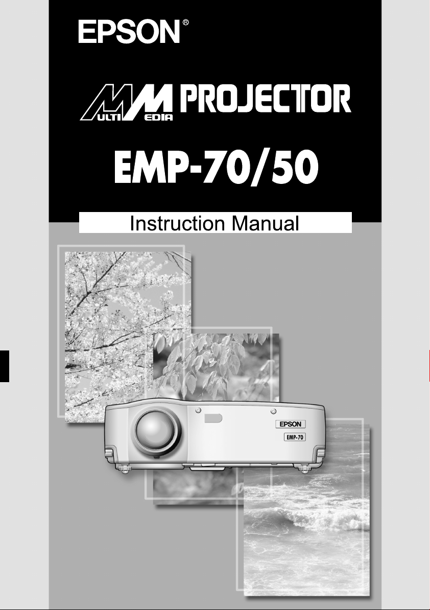
Checking Accessories
When unpacking the projector and accessories from their box, check that the
following items are included.
If any items are missing, contact your vendor or an Epson Service Center.
• Projector main unit
• Lens cover with cord
• Power cord • Computer cable • A/V cable
• USB mouse cable • PS/2 mouse cable • Instruction Manual
• Remote control • Two remote control
batteries
(AA manganese, R6)
(red/white/yellow)
(this manual)
PS/2
• Soft case
Some references to "the unit" or "the projector" in this Manual also refer to
accessories suppl ied with the pr ojector or components sold sep ara te ly f rom the
projector itself.
Page 3

In This Manual
Getting Started
Safety precautions and component names and functions
Setup
Special notes on setup, setup instructions, and screen size and projection
distance details
Projecting Images
Connecting with different devices and projecting and adjusting images
What You Can Do
Functions to get the most out of your projector
Menu Functions (Remote Control Only)
Basic menu functions and settings
Troubleshooting
Troubleshooting projection failure, bad projection, and other problems
Maintenance
Performing lamp replacement and other routine maintenance and care
General Notes
Optional parts, shipping instructions, glossary, index, specifications and
international warranty
1
Page 4

Contents
In This Manual.................................................................................. 1
Contents ............ ............................................................................... 2
Features............................................................................................ 4
1. Getting Started
1.1 Safety Precautions..................................................................... 8
1.2 Component Names and Functions.................................... .. ..... 12
1.3 Remote Control........................................................................ 15
2. Setup
2.1 Spe c ia l Notes on Setup.................. ........................... .. .. ........... 18
2.2 Setup Instructions..................................................................... 19
2.3 Screen Size and Projection Distance Details........................... 20
3. Projecting Images
3.1 Connecting to a Computer....................................................... 22
3.2 Connecting to an A/V Device................................................... 25
3.3 Providing Sound Through an External Audio Device.............. . 27
3.4 Pro je c ting Images. .. .................................................................. 28
3.5 Adjusting Images.................................................. .. .................. 32
3.6 End ing After the Pro j e c ti on................................................. .. .... 35
4. What You Can Do
4.1 Using the Wireles s Mo u s e ........................................................ 38
4.2 Enl arging an Image .................................... .. .. ............. .. ... ........ 40
4.3 Adjusting Image Size............. .. .................... ............................. 41
4.4 Add ing Image Eff e ct s .......... ... ............. .. .. .............. .. ................. 42
4.5 Freezing and Deleting Images.......................... .................. ..... 43
4.6 Displaying Help Screens.......................................................... 44
2
Page 5

5. Menu Functions (Remote Control Only)
5.1 Learning Basic Operations...................................................... 46
5.2 Video Menu ............................. .. .............................................. 47
5.3 Audio Menu ............................................................................. 49
5.4 Effect Menu ............................................................................. 50
5.5 Setting Menu ........................................................................... 51
5.6 Advanced Menu....................................................................... 53
5.7 About Menu............................................................................. 54
5.8 Reset All Menu ........................................................................ 55
6. Troubleshooting
6.1 Possible Failures ..................................................................... 58
6.2 When Indicators Do Not Help............................. ..................... 60
7. Maintenance
7.1 Projector Cleaning, Lens Replacement,
Air Intake Vent Cleaning..................................... ..................... 66
7.2 Lamp Replacement ................................................................. 68
8. General Notes
8.1 Optional Parts.......................................................................... 72
8.2 Ship p in g In s tructions ....... ... .. .......................... ... .. .................... 73
8.3 Glossary .................................................................................. 74
8.4 Index......................... ........................ ....................................... 75
8.5 Specifications .......................................................................... 77
8.6 External Dimensions................................................................ 78
8.7 International Warranty System ................................................ 79
3
Page 6
Features
Compact and Lightweight
The compact, lightweight design of your projector (6.6 liters and roughly 3.1
kilograms (6.83 pounds) ) allows easy carrying.
Clear, Sharp Images
Though compact, your projector provides clear, sharp presentations even in
well-illumi nated areas.
Global Video Signal Compatibility
Your unit projects virtually all of the video signal formats used world-wide,
including NTSC, NTSC4.43, PAL, M-PAL, N-PAL, PAL60, and SECAM.
Improved Video Image Clarity
Projection of distinct video images from composite video and S-video input is
possible.
"Keystone" Correction Function (see pages 33 and 51)
This built-in fun ction all ows easy cor rection o f trapezo idal dist ortion c aused by
projection angle.
Wireless Mouse Remote Control fo r Computer M ouse Operations (see
page 38)
The remote control allows wireless operation of various projector functions,
including cursor/stamp, horizontal bar display, and image enlargement and
reduction.
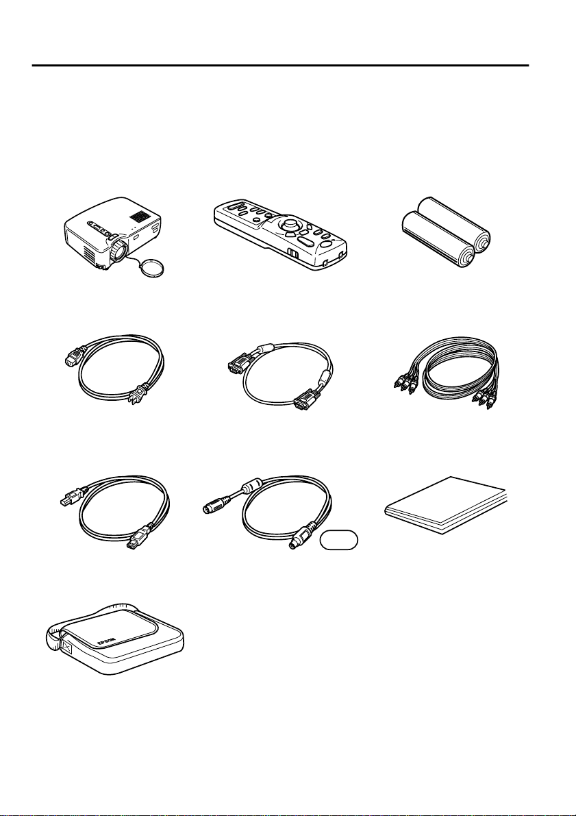
Presentation Effects Function (Remote control Effect button, see page 42)
Use of the remote control Effect button creates effective presentations.
Cursor/Stamp
Horizontal bar
4
Page 7
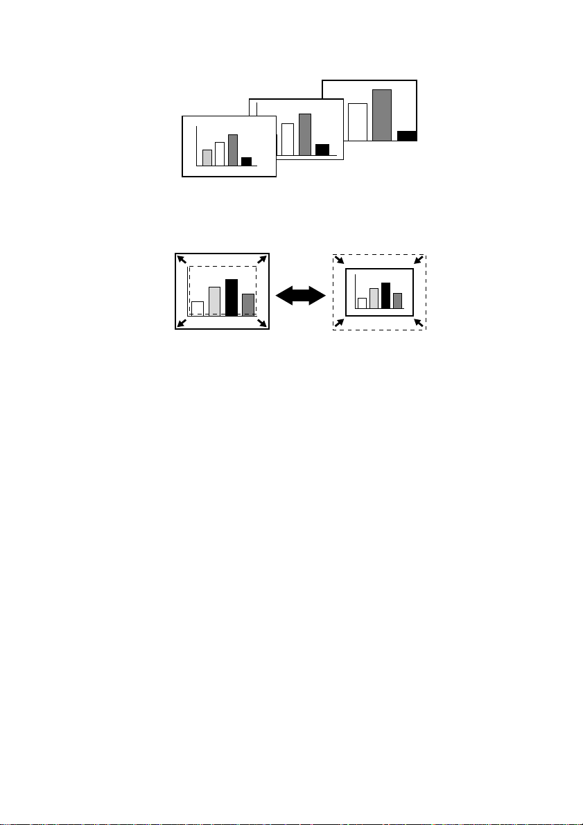
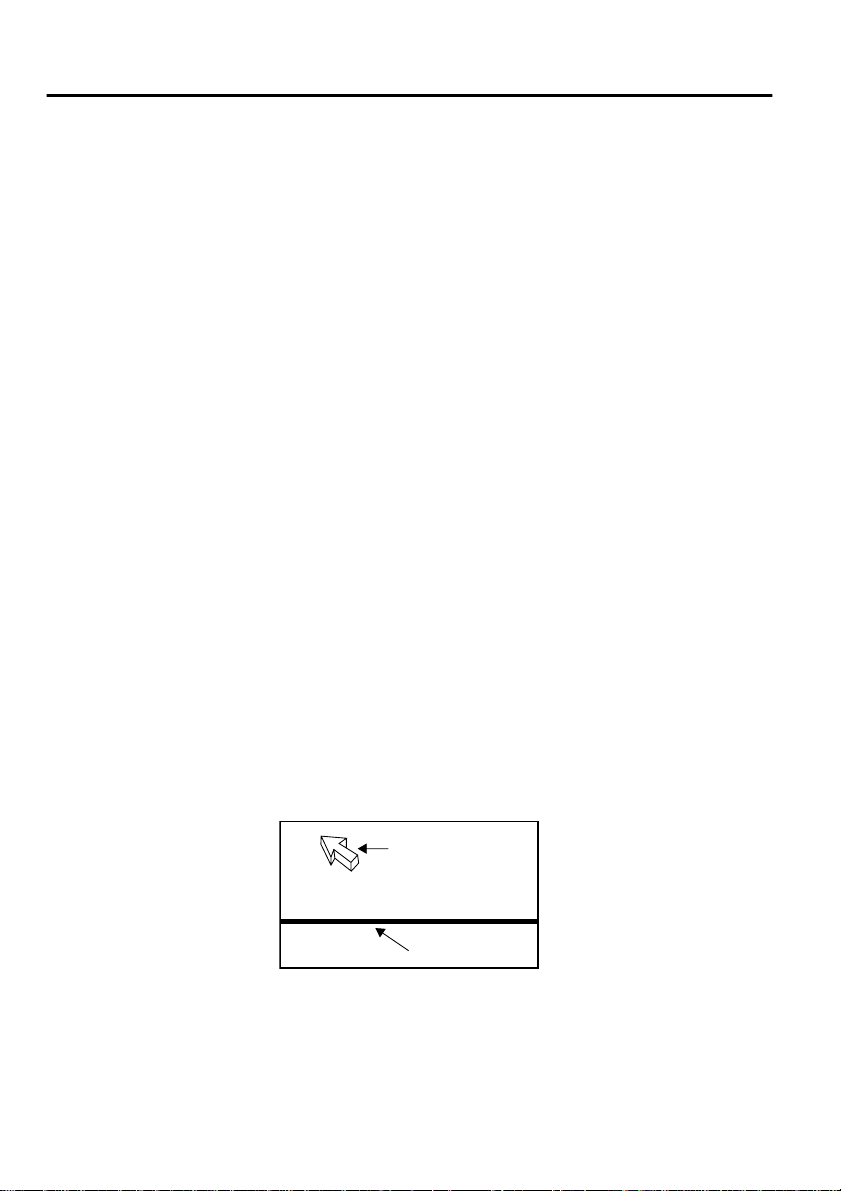
E-Zoom Function (Remote control E-Zoom button, see page 40)
Enlarges an image (from standard to 4x size vertically and horizontally).
Automatic image sizing with Wide/Tele button (see page 41)
Allows image enlargement and reduct ion.
Enlargement Reduction
5
Page 8

6
Page 9

1
Getting Started
1.1 Safety Precautions...........................................8
1.2 Component Names and Functions ................12
1.3 Remote Control.............................................15
7
Page 10

1.1 Safety Precautions
To ensure safe and proper use of your projector, read these safety precautions
completely.
Warning:
Caution:
Improper operation that disregards this symbol may
result in serious injury or death.
Improper operation that disregards this symbol may
result in injury or damage to objects.
Warning:
If any of the following malfunctions occur, immediately shut off and
unplug the projector and consult your vendor or an Epson Service Center.
•Occurrence of smoking, odour, or abnormal noise
•Failure of projection or sound
•Penetration of unit by water or a fo reign object
•Dropping of unit or other damage to the cabinet
Continued use may cause fire or electric shock.
Repairing the unit yourself is hazardous and should never be attempted.
Only trained service personnel should open the projector cabinet, and the
unit should never be disassembled or modified.
The cabinet contains many high voltage components which may cause fire,
electric shock, or other accidents.
Use only a voltage indicated on the unit itself.
Use of a non-designated voltage may cause fire or electric shock.
Check that the power cord specifications are correct.
A power cord which matches the specifications in the country of purchase is
included with the projector. If the pr ojector is used in a differ ent country fr om
the country of purchase, check the power supply voltage and the shape of the
wall outlet in the destinat ion country befo rehand, and make sure tha t you obtain
a proper power cord which matches the specifications for that country.
Do not use a damaged power cord.
Fire or electric shock may result.
Treat the power cord as follows.
•Do not modify the power cord.
•Do not place heavy objects on the power cord.
•Do not bend, twist, or pull the power cord severely.
•Do not run the power cord near heating equipment.
If the power cord becomes damaged, consult your vendor or an Epson Service
Center.
8
Page 11

When the projector is on, never look into the lens.
The intense light may damage your vision. Where small children are present,
take particular care.
Handle the power cord plug and unit connector with care.
Improper handling may cause fire or electric shock.
Treat the power cord plug and connector as follows.
•Do not overload wiring.
•Do not insert a dusty or dirty plug or connector in an outlet.
•Insert fi rmly and comp letely.
•Do not pull out with wet hands.
•Do not use the cable to pull out the plug or connector. Always hold the plug
or connector itself.
The projector cabinet contains lenses, a lamp, and many other glass
components.
When handling any broken components, use care to avoid injury from
fragments, and consult your vendor or an Epson Service Center for repair.
Do not place breakable objects, containers of liquid, medicines, or similar
items on the unit.
Spillage or penetration may cause fire or electric shock.
Do not insert or drop metal, flammable, or other foreign objects into the
intake or exhaust vents of the unit.
Fire or electric shock may result.
Do not leave the unit or the remote control containing batteries in a closed
automobile, area of direct sunlight, air conditioner or heater outlet, or
other high temperature location.
Heat may deform the unit or remote control or cause internal components to
malfunction, leading to fire.
9
Page 12

Caution:
Do not sit, stand, or place heavy objects on the unit.
Tipping or breakage may result and cause injury.
Do not place the unit on an unsteady base, inclined location, or other
unstable area.
The unit may fall or tip and cause injury.
Set up and store the unit out of reach of children.
The unit may fall or tip and cause injury.
Do not place the unit in a humi d or di rt y l ocat ion, near a food preparation
area or humidifier, or in the path of smoke or steam.
Fire or electric shock may result.
Do not block the ventilation slots of the unit. Blockage will cause internal
heat build-up and may result i n fire. Do no t set up the unit in the following
locations.
•In closets, bookshelves, or other cramped locations with poor ventilation
•On carpets, bedding, or blankets.
•Do not cover the unit with blankets, curtains, tablecloths, or other cloths.
If set up near walls, allo w at least 20c m (7.87inches) from all walls.
For safety, always unplug the unit when it will not be used for extended
periods.
Fire may result.
When moving the unit, switch off and unplug the unit and make sure that
all cables are disconnected.
Fire or electric shock may result.
Never remove the lamp immediately after use. After shutting off the
projector, allow an hour for complete cooling.
Heat may cause burns or injury.
10
Page 13

Improper use of batteri es may cause battery damage and leakage of liquid,
resulting in fire, injury, or corrosion of the unit. Observe the following
precautions to ensure safety.
•Do not mix batteries of different type or age.
•Use only batteries specified in the Instruction Manual.
•In case of battery leakage, wipe up the leakage with a cloth or other item and
insert fresh batteries.
•Exchange expired batteries promptly.
•Remove the batteries during extended peri ods of non-use .
•Do not heat the batteries or throw them into a fire or liquid.
•Insert the batteries with correct polarity (+, -).
•If any leakage contacts your hands or other areas, wash promptly with water.
Dispose of batteries in accordance with local collection procedures.
When maintaining the unit, disconnect the power cord at both ends.
Electric shock may resu lt.
Cautions For Use
•Environments outside the temperature range for use (5°C to 35°C) may
cause irregular display, strain of the fan, and malfunction.
•Environments outside the temperature range for storage (-10°C to 60°C)
may cause malfunction and deformation of the cabinet. Take particular
care not to leave the projector for extended periods in locations exposed
to direct sunlight.
•Do not attempt projection wit h the lens cover in place. Heat may deform
the lens cover.
•The LCD panel is a product of extremely high-precision technology and
contains more than 99.99% functional pixels, but you should bear in
mind that less than 0.01% of the pixels are non-functioning or light
improperly.
11
Page 14
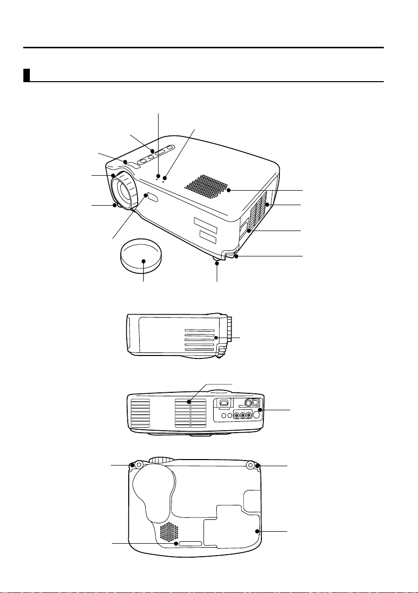
1.2 Component Names and Functions
Projector Unit
[Front]
Operation Display Indicator
Operating Panel
Wide/Tele Button
Focus Ring
Front Foot
Remote Control Receiver
Problem/Alarm Display Indicator
Speaker
Air Exhaust Vent
Power Terminal
Foot Lever
[Side]
[Rear]
[Bottom]
12
Front Foot
Rear Foot
Lens Cover
Front Foot
Air Intake Vent
Air Intake Vent
Input/Output T erminals
Front Foot
Lamp Cover
Page 15
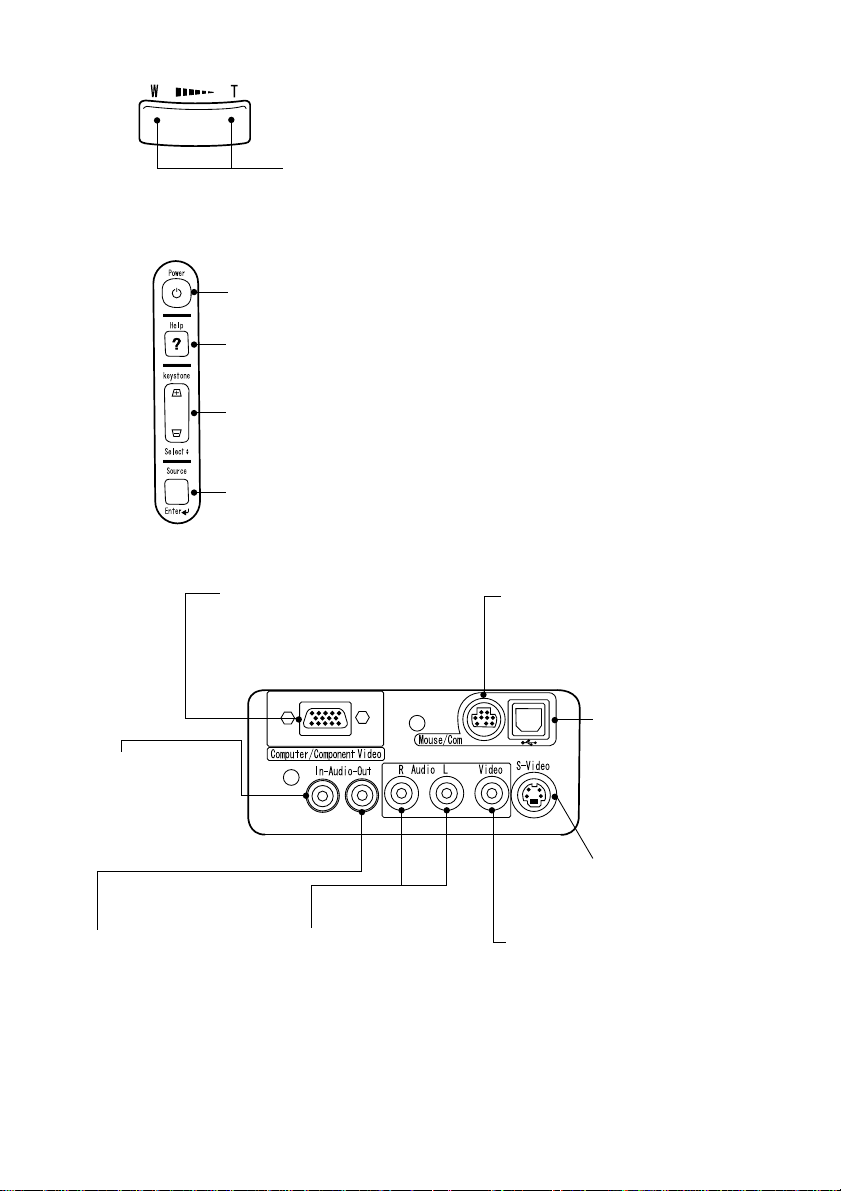
[Wide/Tele Button (see page 41)]
Mouse/Com Terminal (See page 39)
Used when using the remote control as
a wireless mouse.
USB Mouse Terminal
(See page 39)
Used when using the
remote control as a
wireless mouse.
S-Video Terminal (See
page 25)
For input of S-video
signal from A/V device.
Composite Video Termina l
(See page 25)
For input of Composite Video signal
from A/V device.
L/R Audio Terminals
(See page 25)
For input of audio signal
from A/V device.
Audio Out Terminal
(See page 27)
For output of audio signal
from projector.
Audio In Terminal
(See page 24)
For input of audio
signal from
computer.
Computer/Component Video
Terminal (See page 24)
For video signal input from
computer or component video.
Press the right side of the button (Tele) to reduce the image.
Press the left side of the button (Wide) to enlarge the image.
[Operating Panel]
Power Button (see pages 29, 35)
Switches power on and off.
*Press twice to turn the power off.
Help Button ( See page 44)
Displays help screen.
Keystone (Select) Button (see pages 33, 51)
Adjust when screen is distorted trapezoidally.
Source (Enter) Button (See page 30)
Toggles the video source between Computer, S-Video, and Composite video.
[Input Terminals]
13
Page 16
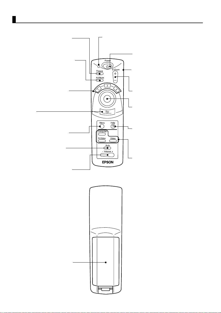
Remote Control
[Front]
Freeze Button (See page 43)
Temporarily stops a moving picture.
To release the freeze, press the
button again.
A/V Mute Button (See page 43)
Temporarily eliminates picture and
sound.
To release muting, press the button
again or adjust the volume.
Effect Button (See page 42)
Executes an assigned effect
function.
Esc Button
Cancels an executing function and
serves as the right mouse button.
Menu Button (See page 46)
Displays or cancels menus.
Auto Button (See page 34)
Optimizes computer video.
Volume Button (See page 34)
Adjusts volume.
Indicator
Lights during signal output from remote control.
Power Button (see page 29, 35)
Switches projector power on and off.
*Press twice to turn the power off.
R/C On Off Button (see pages 29,
36)
Switches remote control power on
and off.
E-Zoom Button (See page 40)
Executes the E-Zoom function.
Enter Button
Used for scrolling, menu item
selection, and as the left mouse
button.
Help Button (See page 44)
Provides topic-specific explanation
for addressing problems.
Use this button when problems
occur.
Computer, S-Video, Video Button
(See page 30)
Switches to the selected video
source.
14
[Back]
Battery Cover
Page 17
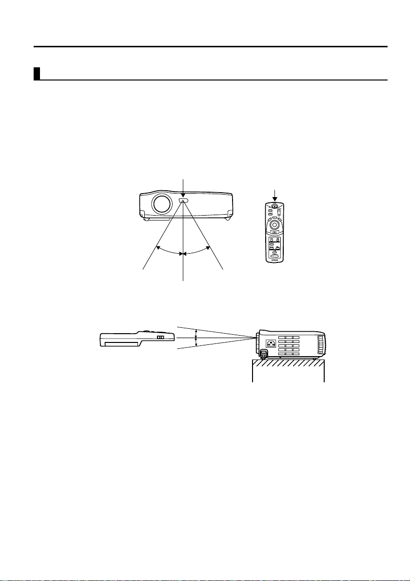
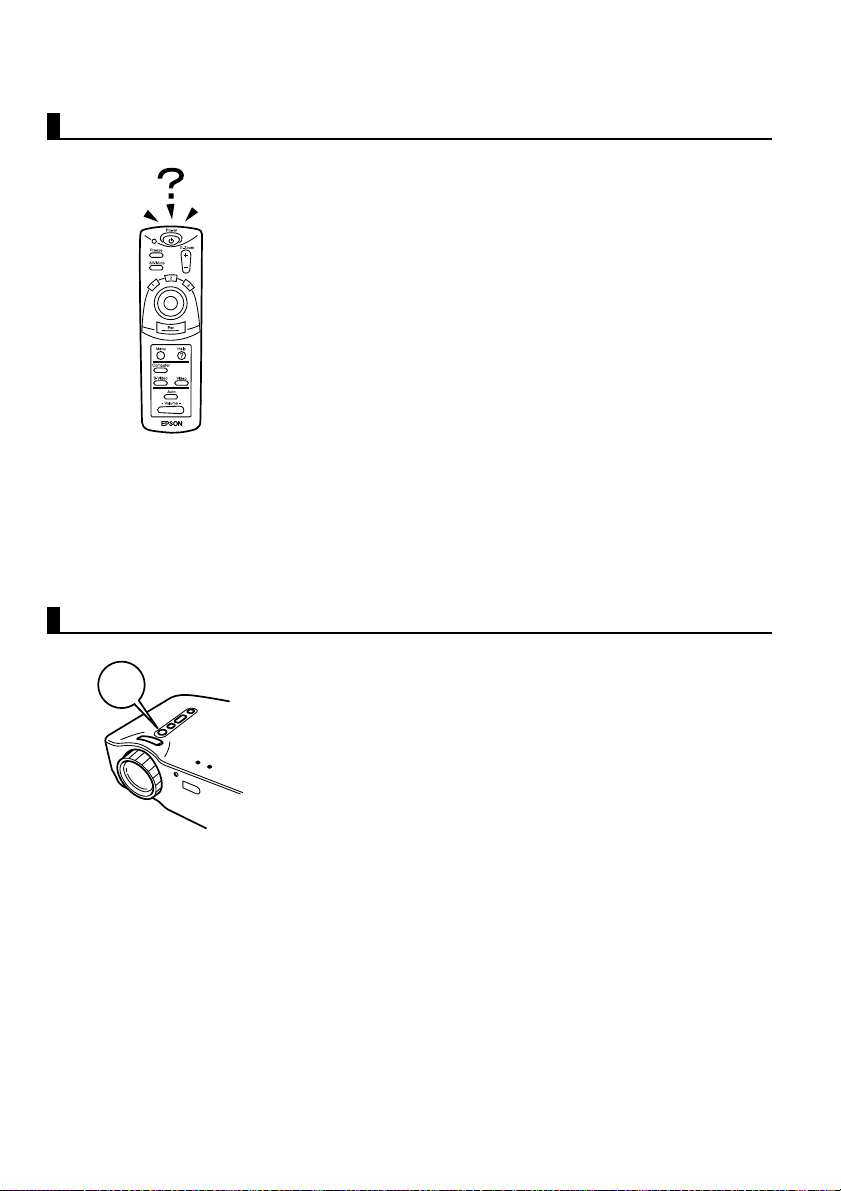
1.3 Remote Contr ol
Operating Range
The remote control may not operate beyond certain distances and angles from
the receiver on the projector. Observe the following conditions during use.
[Operating Distance : Approximately 10m (393.70inches) ]
[Operating Area:]
Horizontally
Remote Control Receiver
Approximately 30º Approximately 30º
Remote Control
Transmitter
Vertically
Approximately 15º
Point:
• The remote control R/C On Off switch must be switched to "On" to use the remote
control.
• Point the remote control towards the remote control receiver on the projector unit.
• Certain screens may shorten the operating distance (approximately 10m
(393.70inches) ) of the remote control when the control is pointed towards the screen
to reflect its signal during use.
• Situate the remote control receiver out of direct sunlight, fluorescent light, and
similar li ght sources .
These may cause the remote control to malfunction.
• If the remote control malfunctions or stops operating, the batteries may need
changing.
Replace the batteries with a fresh set.
15
Page 18
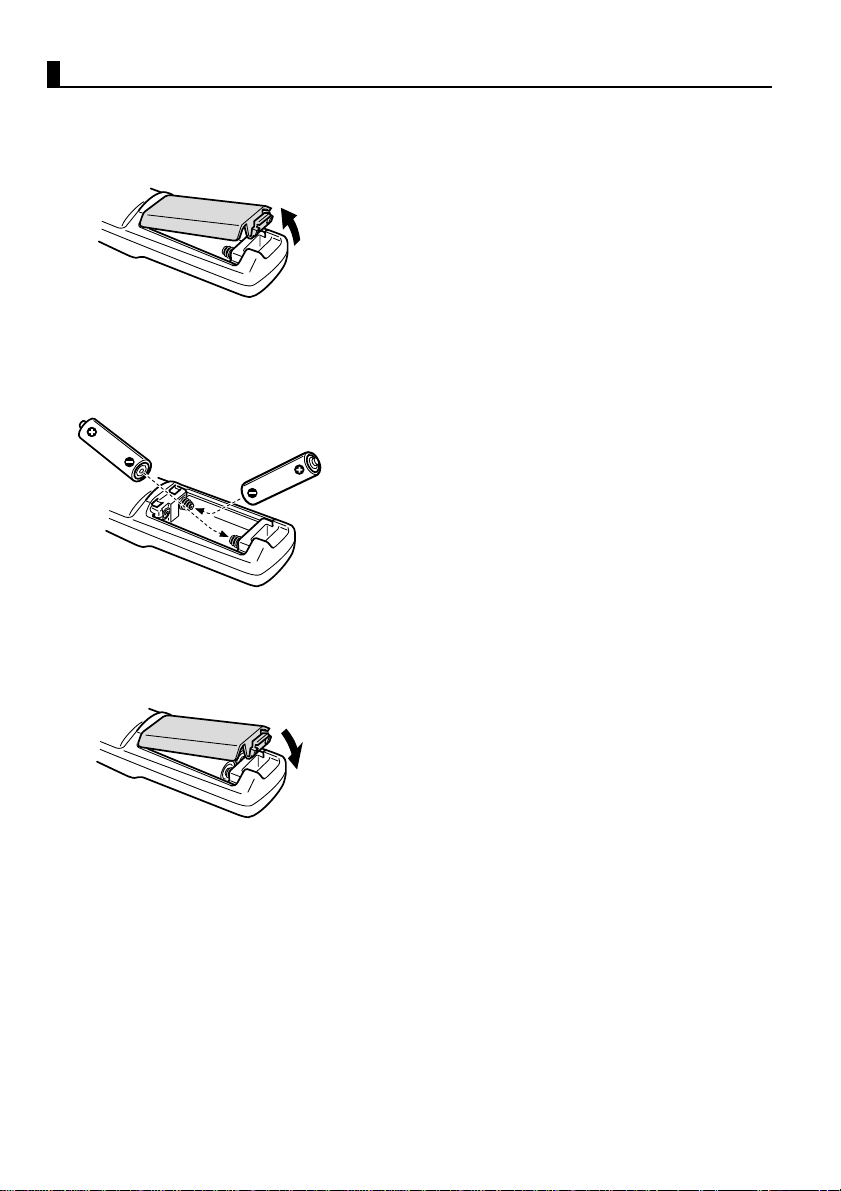
Inserting Batteries in the Remote Control
This section describes how to insert batteries in your remote control.
1.
Remove the battery cover.
Slide the catch of the battery cover in the
direction shown by the arrow.
Caution:
Be sure to use fresh batteries of the same type as
the old.
2.
Insert batteries.
Be sure to match the polarity to that
indicated on the remote control.
Point:
•Battery type
(2) AA manganese cells (R6)
• Use o f 30 minutes per day will requir e a
change of batteries approximately every 3
months.
16
3.
Replace the battery cover.
Press the battery cover into the remote
control until it clicks firmly into place.
Page 19

2
Setup
2.1 Special Notes on Setup..................................18
2.2 Setup Instructions..........................................19
2.3 Screen Size and Projection Distance Details...... 20
17
Page 20
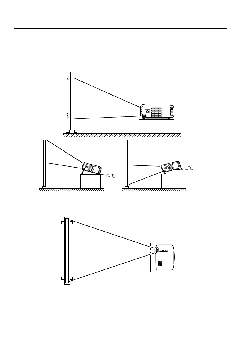
2.1 Special Notes on Setup
The best picture is obtained when the projector and screen are set up facing
each other directly, as shown below.
Set your projector and screen up this way.
[View from right or left]
9
90º
1
Upward approximately 15º
15º
Downward approximately 15º
15º
Keystone correctio n allows corr ection of t rapezoid al distor tion (see pa ges 33, 51).
[View from above or below]
90º
Caution:
• Do not block the air exhaust vent on the side of the projector or the air intake vents on
the right side and rear of the projector.
• Do not place the unit in direct contact with air conditioner, heater, or other
ventilation currents.
• When setting up the projector near walls, allow at least 20cm (7.87inches) from all
walls.
18
Page 21
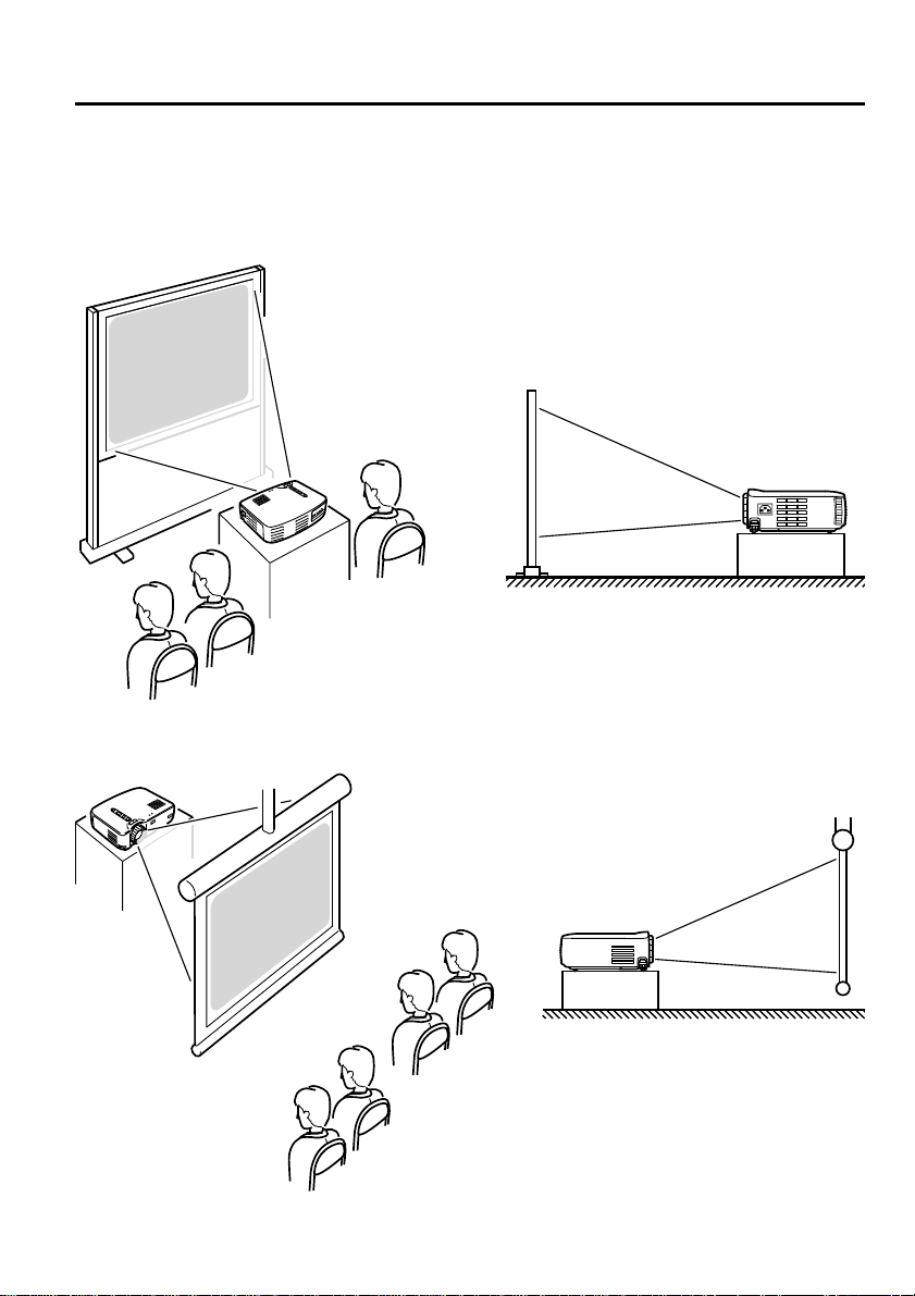
2.2 Setup Instruction s
Your projector allows projection in the following two ways. Set up the
projector as your location requires.
[Viewing from the front]
[Projection on a semi-transparent screen and viewing from the rear]
19
Page 22
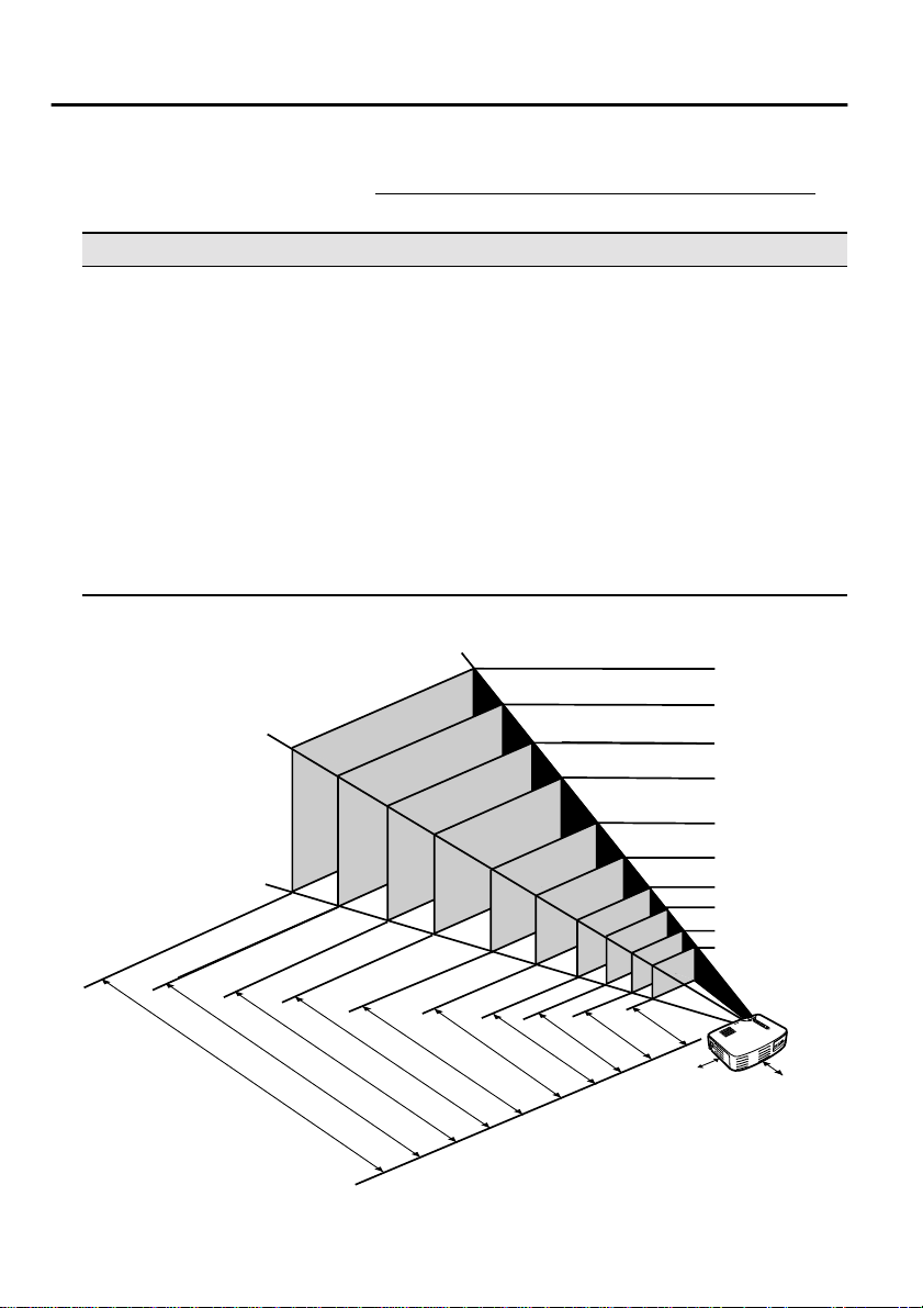
2.3 Screen Size and Projection Distance Deta ils
Select a distance from lens to screen that provides your desired screen size.
The recommended distance is 1.0 m (39.37inches)—13.1 m (515.75inches)
Refer to the fo llowing table for setup.
Screen size (cm) Approximate projection distance* (m (inch) )
Size 300” (610x460) 11.0—13.1 (433.07—515.75)
Size 200” (410x300) 7.3—8.7 (287.4—342.52)
Size 150” (305x228) 5.5—6.5 (216.54—255.91)
Size 120” (244x183) 4.4—5.3 (173.23—208.66)
Size 100” (200x150) 3.7—4.3 (145.67—169.29)
Size 80” (160x120) 2.9—3.4 (114.17—133.86)
Size 60” (120x90) 2.2—2.6 (86.61—102.36)
Size 40” (81x61) 1.5—1.7 (59.06—66.93)
Size 30” (61x46) 1.1—1.2 (43.31—47.24)
Size 28” (57x43) 1.0—1.1 (39.37—43.31)
* Use the "approximate projection distance" as a guide to setup. Projection
conditions and other factors can affect results.
Size 300"
)
m
c
(
0
6
4
x
0
1
6
0
0
3
x
0
1
4
8
2
2
x
5
0
3
3
8
1
x
4
4
2
0
5
1
x
0
0
2
0
2
1
x
0
6
1
0
9
x
0
2
1
1
6
x
1
8
6
Size 200"
Size 150"
Size 120"
Size 100"
Size 80"
Size 60"
Size 40"
Size 30"
6
4
Size 28"
x
1
57x43
.
5
.5
-
8
7
.4
-
3
4
2
.
7
5
i
n
c
h
)
4.4-5.3 (173.23-208.66)
6
.5
(
2
1
6
.5
4
-
2
5
.5
5
2
)
-
4
.3
.9
1
)
7
1
.3
1
.
-
0
8
-
.7
1
3
(
.
2
1
m
(
4
3
3
.
0
7
-
5
1
5
3
.7
Point:
A keystone correction will reduce screen size.
20
(
1
4
5
.6
(114.17-133.86)
(86.61-102.36)
2.9-3.4
7
-
1
6
9
.2
9
)
(39.37-43.31)
1.1-1.2
1.0-1.1
*
)
m
(
2
.
0
.
2
0
(
m
)
*
(59.06-66.93)
1.5-1.7
2.2-2.6
(43.31-47.24)
*If installing to a wall, leave a space of at
least 20 cm between the projector and the wall.
Page 23

3
Projecting Images
3.1 Connecting to a Computer ............................22
3.2 Connecting to an A/V Device .......................25
3.3 Providing Sound Through an External
Audio Device ................................................27
3.4 Projecting Images..........................................28
3.5 Adjusting Images ..........................................32
3.6 Ending After the Projection ..........................35
21
Page 24

3.1 Connecting to a Computer
Computers which can be connected
Some computer models may not allow connection, and others may allow
connection but not projection.
Make sure that the specifications of the computer you are using for connection
meet the following two requirements.
[The computer must have a video signal output port]
Make sure that the computer has a port that outputs a video signal.
A port that outputs a video signal is called an "RGB port", "monitor port", or
"video port" or the like.
Consult the section de scribing "connecti on to an external mo nitor" or th e like
in the instruction manual for the computer that you are using, and make sure
that the computer has a video signal output port.
Computers w ith an integrated moni tor and other c omponents as well as
notebook personal computers may require separate purchase of an external
output port.
In other cases, an external output port cannot be attached.
[The resolution and fre quency of the compute r must be withi n the range of
specifications shown on the following page]
The resolution and frequency of the video signal output by your computer
must be compatible with your projector in order to allow projection (some
computers allow partial projection, but clear projection cannot be obtained).
Check the resolution and frequency of the video signal in the instruction
manual of the computer you are using for projection.
22
Page 25

Compatible Mode Chart for Connectable Computers
If the resolution and frequency of the video signals which are output from the
computer do not corres pond to a ny of t he valu es in t he tabl e belo w, tho se vide o
signals cannot be projected. (In some cases it may be possible to project such
signals, but they will not produce clear images.)
Check the instructi on manual for the computer fo r de tails on the resoluti on a nd
frequency of the video signals.
Furthermore, some computers may let you change the output resolution. If this
is the case, change the resolution to a value in the table below.
Frequency used for
Signal (Resolution)
(dots)
PC (RGB)
compatible modes
PC (YUV)
compatible modes
Video
compatible modes
Signal
640 x 350 VGAEGA 60 1024 x 560 800 x 437
640 x 400 VGACGA 60 1024 x 640 800 x 500
720 x 400 VGA Text 70 1024 x 568 800 x 444
720 x 350 VGA Text 70 1024 x 497 800 x 388
640 x 480 VESA 60/72/75/85 1024 x 768 800 x 600
800 x 600 SVGA 56/60/72/75/85 1024 x 768 800 x 600
1024 x 768 XGA 43i/60/70/75/85 1024 x 768 800 x 600
1152 x 864 SXGA1 70/75/85 1024 x 768 1280 x 960 SXGA2 60/75/85 1024 x 768 -
1280 x 1024 SXGA3 43i/60/75/85 960 x 768 -
640 x 480 MAC13 66 1024 x 768 800 x 600
832 x 624 MAC16 75 1024 x 768 800 x 600
1024 x 768 MAC19 60/75 1024 x 768 800 x 600
1152 x 870 MAC21 75 1024 x 768 800 x 600
- HDTV525I 50/60 1024 x 768 800 x 600
- HDTV525P 50/60 1024 x 768 800 x 600
1280 x 720 HDTV750P 50/60 1024 x 576 800 x 450
1920 x 1080 HDTV1125I 50/60 1024 x 576 800 x 450
- NTSC 60 1024 x 768 800 x 600
- PAL 50 1024 x 768 800 x 600
- SECAM 50 1024 x 768 800 x 600
Refresh rate
(Hz)
resized displays
(when resizing is on)
(dots)
EMP-70 EMP-50
23
Page 26
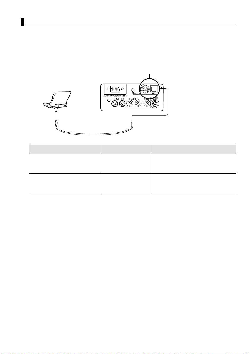
Connecting to a Computer
•Before connecting, switch off power to the projector and computer.
•Check that cable and terminal interfaces match each other.
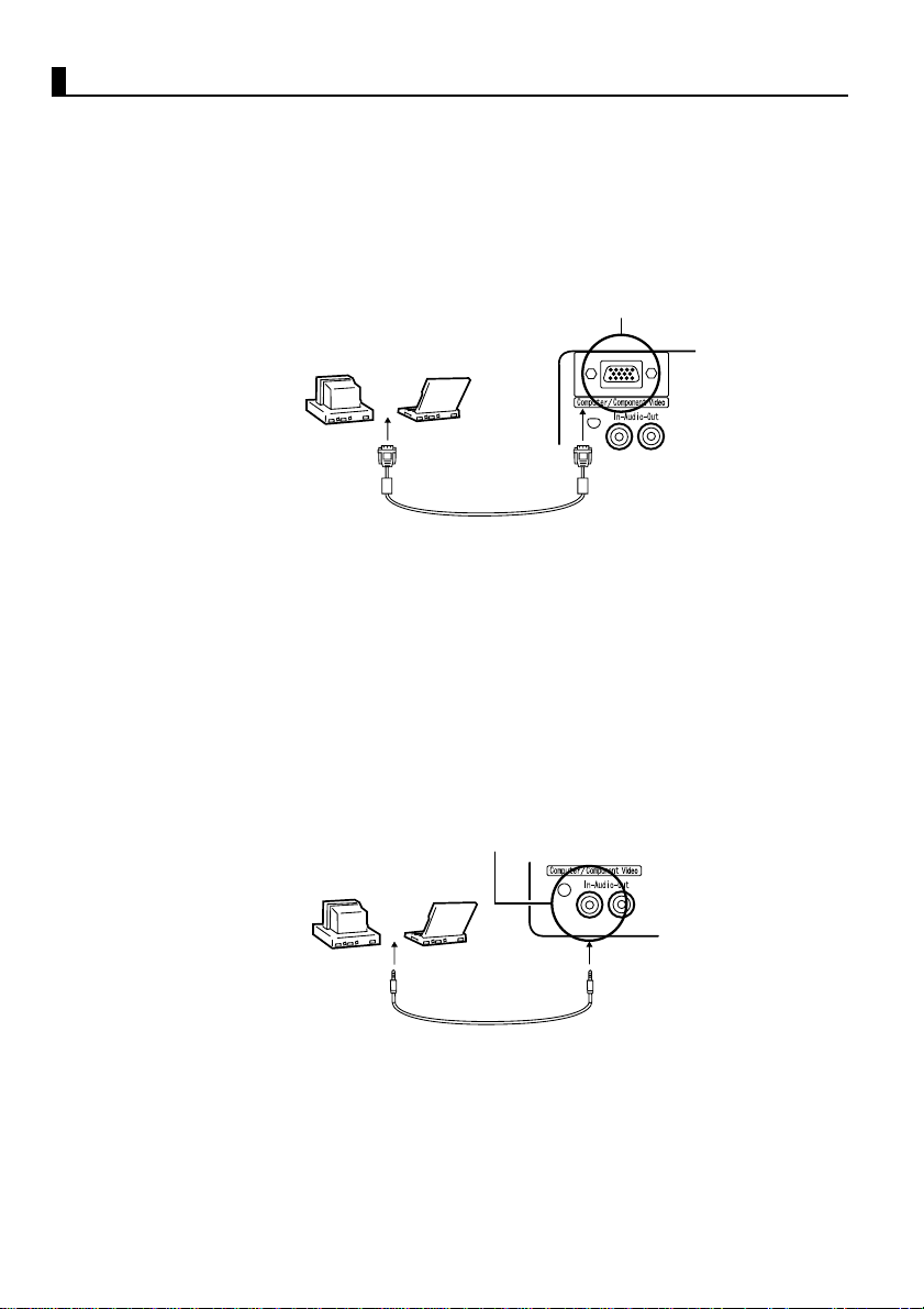
[Projecting Computer Video]
You can make presentations on a large screen by projecting computer video
from your projector.
Computer T erminal
Computer Monitor Port
(Video Port)
Computer Cable
(supplied with
projector)
* If your computer port style is not a mini D-Sub 15-pin interface, use a connection
adapter that provides this interface.
When connecting to a Macintosh, you may need an optional Mac desktop adapter.
Point:
• When using the projector, do not bundle power cords and computer cables together.
• Some computer models may require a connection adapter during connection. Consult
your computer instruction manual or the computer vendor.
[Outputting Computer Audio From Your Projector]
You can output computer audio from a built-in speaker in your projector.
Your projector allows output at a maximum 1W.
Audio In Terminal
Computer Audio
Output Port
Point:
• When computer video has been selected or when audio input is specified on the
computer by menu, your projector outputs an audio signal from the computer.
• Purchase an audio cable that matches the terminal style of your computer's output
terminal and the projector's Audio In terminal (stereo mini jack).
Audio Cable
(sold separately)
24
Page 27
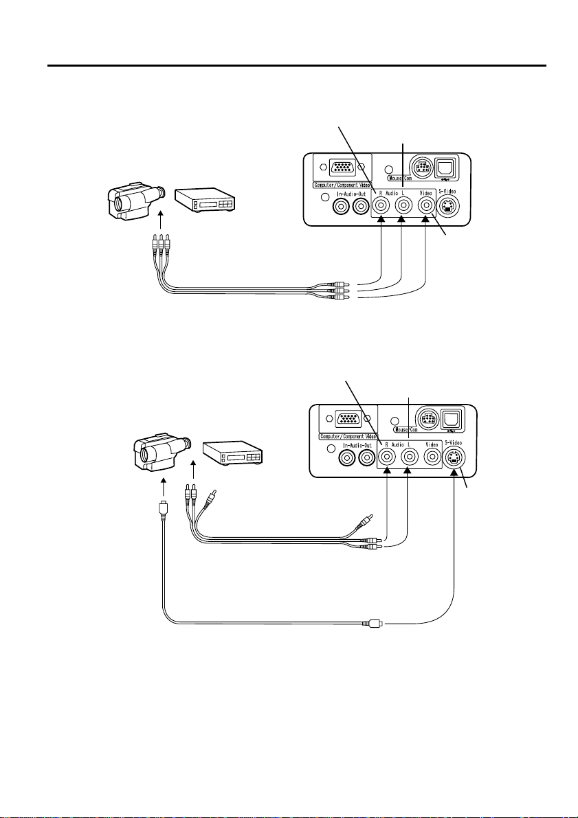
3.2 Connecting to an A/V Device
[Inputting a Composite Video Signal]
R-Audio Terminal (Red)
L-Audio Terminal (White)
To video terminal (Yellow)
To (L) audio terminal (White)
To (R) audio terminal (Red)
A/V Cable (supplied with projector)
[Inputting an S-Video Signal]
R-Audio Terminal (Red)
L-Audio Terminal (White)
Video
Terminal
(Yellow)
To S-Video
Terminal
A/V Cable
(supplied with projector)
To (L) audio terminal (White)
To (R) audio terminal (Red)
S-Video Cable (sold separately)
S-Video
Terminal
25
Page 28

[Inputting a Component Video Image Signal]
•If using a component video cable
Computer/Component Terminal
DVD player, etc.
To Y terminal (Green)
To Pb or Cb terminal (Blue)
To Pr or Cr terminal (Red)
Component video cable (optional part)
A/V cable (supplied with projector)
To (L) audio terminal (White)
To (R) audio terminal (Red)
•If using a D terminal cable
Computer/Component Terminal
DVD player, etc.
R-Audio Terminal (Red)
L-Audio
Terminal
(White)
R-Audio Terminal (Red)
To D-terminal
L-Audio
Terminal
(White)
D-terminal cable (optional part)
A/V cable (supplied with projector)
To (L) audio terminal (White)
To (R) audio terminal (Red)
Point:
• When projecting a component video image, select "YCbCr" or "YPbPr" in the Video
> Input Signal menu.
Select "YCbCr" if using a DVD player, and select "YPbPr" if using a HDTV video
source.
• To change the aspect ratio of the projected image between 4:3 and 16:9, select Video
> Aspect Ratio menu.
26
Page 29

3.3 Providing Sound Through an External
Audio Device
Connecting the Audio Out terminal of your projector to a PA system, active
speaker system, or other speakers with built-in amplifiers provides powerful,
pleasing sound.
Use a separately sold audio connection cable (pin ring) connecting to a 3.5mm
(0.14inches) stereo mini-jack plug.
Audio Out Terminal (Stereo mini jack)
External Audio Device
Audio Connection Cable
(sold separately)
Point:
• Insertion of pin plugs into the audio output terminals provides automatic external
output of audio. Audio will no longer be output from the projector speaker.
• Though the projector outputs audio for projected video images, in the case of A/V
devices, the audio output corresponds to the a udio dev ices connec ted to the L/R a udio
terminals.
• Before purchasing an audio connection cable, thoroughly check the connection
interface style of the external audio devices you are connecting.
27
Page 30

3.4 Projecting Images
Here we begin projecting images from an A/V device.
Preparation
Warning:
• Never look into the lens when the projector is switched on. The intense light can
damage your vision.
• Use only the power cord supplied. Use of other cables may cause fire or electric
shock.
Caution:
• Do not attempt projection wi th the len s cover in place. Heat may deform the lens
cover.
1.
Power Terminal
Power cord
Power Cord Connector
Check that the projec tor and computer or A/
V device are connected.
2.
Remove the lens cover.
3.
Attach th e power cord (supplied w ith
projector) to the projector.
Align the power cord connector with the
power terminal on the projector and insert
the connector firmly an d completely into the
terminal.
28
Power cord
Power Cord
Plug
Outlet
4.
Insert the plug end of the power cord in an
outlet. The operation display indicator will
light with an orange color.
Point:
Buttons cannot be operated while the operation
display indicator is flashing orang e .
Page 31

Projection
When preparations are complete, you are ready for projection.
1.
To use the remote contr ol, turn the remote
control R/C On Off switch to "On".
2.
Press the Power button to switch power on.
The operation display indicator begins to
flash green, and projection begins.
After approximately 30 seconds, the
operation display indicator changes from
flashing green to steady green.
"No-Signal" is displayed.
Depending on your settings,
there may be no display.
(See page 51)
The operation display indicator
lights green.
29
Page 32
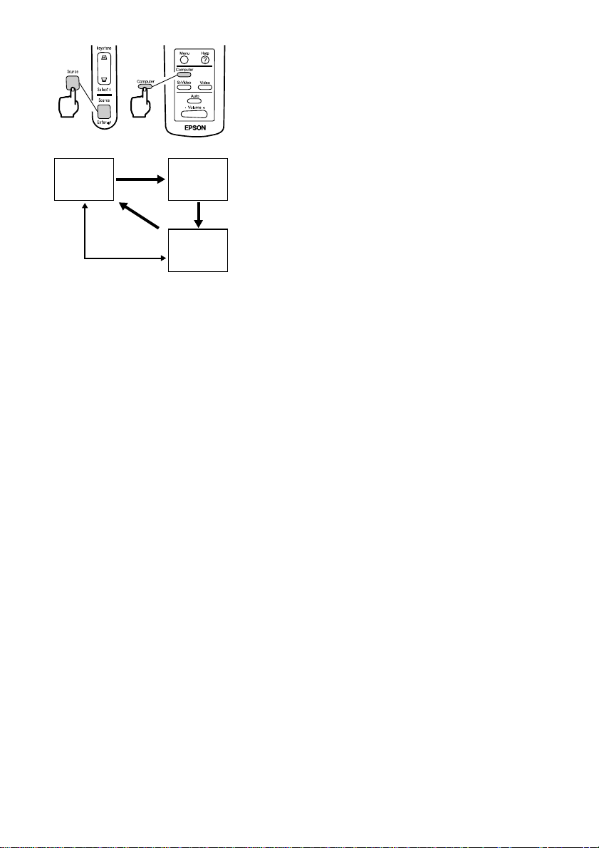
Computer
When no S-Video
input
S-Video
Video
3.
Press the Source button to select the video
source you wish to project.
Each time the Source button is pressed, the
video source cycles between Computer, SVideo, and Video.
If there is no input at the S-Video terminal,
the Source button switches the video source
from Computer to Video.
Point:
• When you use the remote control to select the
video source you wish to project, you can
switch the source by pressing any of the
Computer, S-Video, or Video buttons.
• If projecting a component video picture,
change the setting to Computer.
4.
Switch on power to the computer or A/V
device to begin projection.
The "No-Signal" display disappears, and a
video signal from the computer or A/V
device is projected.
Point:
• If the "No-Signal" display remains, check the
connections again.
• If the same static image is projected for some
time, the video projection may contain an
afterimage.
30
Page 33

[Settings for notebook and integrated LCD computers (when connected)]
When a notebook or integrated LCD computer is connected to the projector,
some computers require key commands or settings to change the output
destination of a video signal.
Press "Fn" and "F0" simultaneously to change the setting.
For details, consult the instruction manual of the computer you are using.
Manufacturer Output Switching Example
NEC
Panasonic
Toshiba
IBM
SONY
Fujitsu
Macintosh After restarting, the monitoring and sound on the
control panel are set to mirror the computer.
Point:
Some computers may not be able to have images displayed on the computer screen at
the same time as they are being projected. In such cases, use only external output.
"Fn"+"F3"
"Fn"+"F3"
"Fn"+"F5"
"Fn"+"F7"
"Fn"+"F7"
"Fn"+"
F10
"
31
Page 34
3.5 Adjusting Images
This section describes how to obtain the best video performance.
See "2. Setup" for details on setting-up position and projection size.
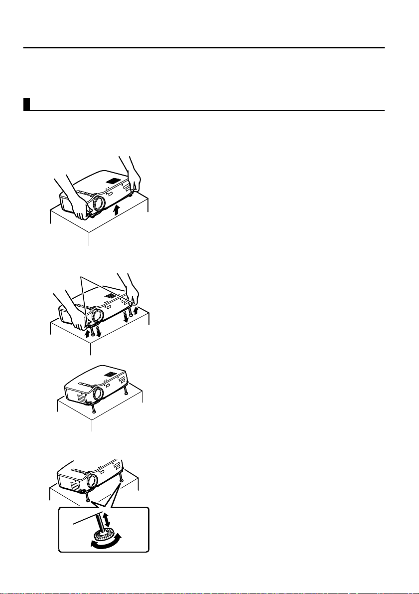
Adjusting the Image Projection Angle
Adjust the projection angle of the projector.
Adjust the projector to face the screen as directly as possible .
1.
Lift the projector to your desired angle of
projection.
Foot Levers
Raise
Lower
2.
Use your fingers to pull up the foot levers.
Front feet emerge.
3.
Release the foot levers.
4.
Make fine adjustments to the height.
Turn the lower portion of the front feet to
make fine adjustments to height.
Point:
Setting back the front feet (see page 36)
32
Page 35
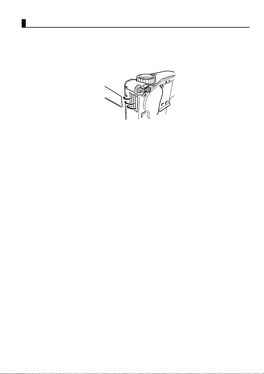
Adjusting the Focus
This section describes how to adjust the video focus.
1.
Turn the focus ring on the projector to adjust
the focus.
Point:
• Focus cannot be achieved if the lens is dirty or
covered with condensation. Wipe off any dirt
or condensation (see page 66).
• If adjustment does not succeed, make sure the
setup distance is between 1.0m (39.37inches)
and 13.1m (515.75inches) .
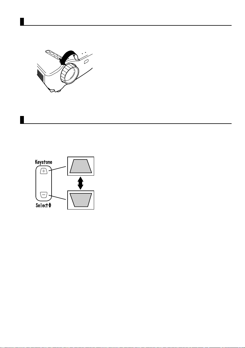
Keystone Correction (Using Projector Button)
When the foot levers are used to change the projection angle, the keystone
correction function can be used to correct trapezoidal distortion upward or
downward by roughly 15°.
1.
Press the Keystone button on the projector
to minimize the trapezo idal distor tion.
Point:
• A keystone correction reduces screen size.
• The keystone correction is stored in memory.
You will need to readjust the image if the
projector is moved to a different location or t he
projection angle is changed.
• If a keystone correction makes the image
noticeably uneven, reduce the video sharpness
with the menu commands Video > Sharpness
(see page 48).
33
Page 36
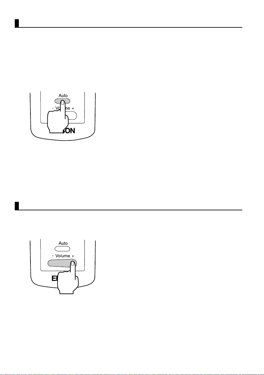
Adjusting Images (Remote Control Only)
[Optimizing Computer Video (Using the Auto button)]
This function applies automatically optimized adjustment values to a
computer input signal.
If the input is a video signal, this function does not operate.
Adjusted values set automatically are "Tracking", "Position (vertical and
horizontal)", and "Sync" .
Point:
• This function cannot optimize the adjustment
for some signal types. In these c ases, use the
Video Menu commands to perform adjustment
(see page 47).
• When functions such as E-Zoom or A/V muti ng
are engaged, press the Auto button to
disengage these functions before adjustment.
[Opening a Menu For Adjustment]
Press the Menu button and perform adjustment using the Video Menu.
For details, refer to "Menu Screen Operations (Remote Control Only)" (see
page 45).
Adjusting the Volume (Remote Control Only)
Press the Volume +, - button to adjust the volume to an easily au dible listening
level.
Point:
Adjustment is not available if there is no audio
signal.
34
Page 37

3.6 Ending After the Projection
Ending
1.
Press the Power button. A "Power Off"
confirmation message is displayed.
2.
Press the Power button again.
The projector lamp goes out, the operation
display indicator flashes orange, and after
cool-down is complete, the indicator
switches to steady orange.
Point:
If you do not wish to shut the power, press
another button.
Or, if no action is taken, the messa ge disapp ears
after 7 seconds.
Operation display indicator
lights orange.
3.
Check that the operation display indicator
lights orange.
Point:
• The flashing orange operation display
indicator indicates that cool-d own* (which
takes about 2 minutes) is in progress. Buttons
cannot be operated during cool-down (see
page 74).
• If the power cord plug is pulled out of the
outlet, the operation display indicator will go
out.
35
Page 38
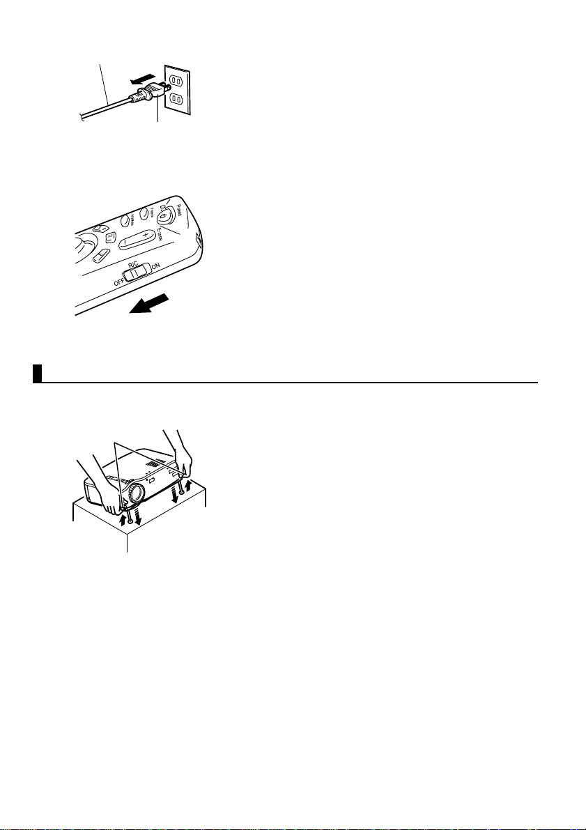
4.
Power cord
Power Cord Plug
Outlet
Pull the power cord plug out of the outlet.
Caution:
Do not pull the power co rd plug out of the outl et
while the operation display indicator is flashing
orange. This may cause a malfunction or
shorten the projector lamp life.
5.
Set the remote control R/C On Off switch to
Off.
Point:
Unless the remote control R/C On Off switch is
switched off, a small amount of current will be
supplied to the remote control and exhaust the
batteries. If the remote control will not be used
for a long period or you are moving the unit, set
the remote control R/C On Off switch to Off.
Storage
When you are finished projecting, retract the foot levers into the unit.
36
Foot Levers
1.
Support the projector unit with your hands,
pull upward on the foot levers with your
fingers, and lower the unit slowly.
2.
Attach the lens cover.
Page 39

4
What You Can Do
4.1 Using the Wireless Mouse ............................38
4.2 Enlarging an Image .......................................40
4.3 Adjusting Image Size....................................41
4.4 Adding Image Effects ...................................42
4.5 Freezing and Deleting Images.......................43
4.6 Displaying Help Screens...............................44
37
Page 40
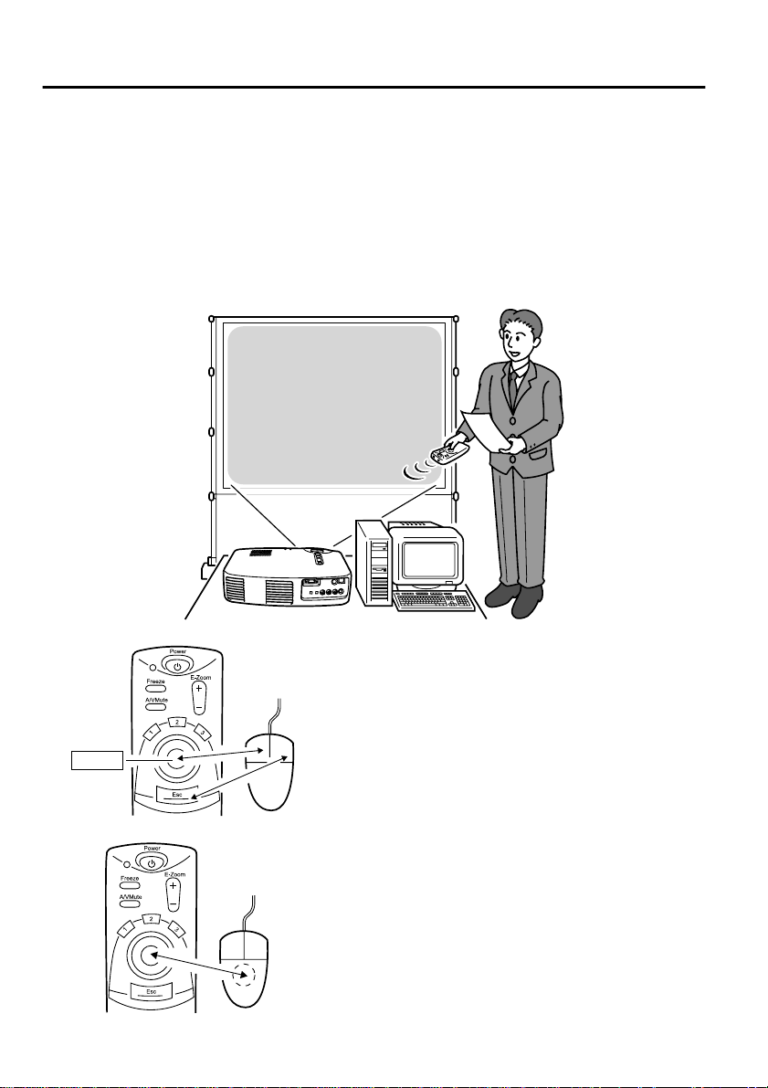
4.1 Using the Wireless Mouse
The remote control included allows you to cont rol a computer's mouse
operations at a separate location.
• The Esc button has the same action as a right mouse button, and the Enter
button has the same action as a left mouse button.
Mouse operation by remote control allows you to make a presentation at
the screen without assistance.
〔
Presenter
Unassisted presentation is possible
〕
38
Enter
Button
Remote Control Mouse
Remote Control Mouse
Point:
• If mouse button functions are swapped on your
computer, the functions on the remote control
also change as follows.
Esc Button: Left mouse button
Enter Button: Right mo us e butto n
• This function cannot be used while an Effect
Function, E-Zoom function, menu function, or
Help function is in use.
Page 41
Making a Connection
Before making a connection, switch off power to the projector and computer.
Caution:
• Connecting a non-USB mouse cable with the power on can cause malfunction or
failure.
• Use only the mouse cable supplied. Any other cable may cause failure.
Mouse/Com, USB Terminal
Mouse/USB Port
Mouse Cable
(supplied with projector)
Computer Mouse Cable Connection Method
IBM PC/AT Compatible
(DOS/V Machine)
Computer for US B* Mouse
(see page 74)
PS/2 Mouse Cable Connect the computer mouse
port and the projector Mouse/
Com terminal.
USB Mouse Cable Connect the computer USB port
and the projector USB mouse
terminal.
When using a USB mouse, note the following.
• Windows
The only compatible models are those pre-installed with the standard USB
interface configuration in Windows2000 and Windows98.
Operation is not guarante ed in envir onments upgraded from Windows 3.1 and
Windows95 to Windows98 and Windows2000.
• Macintosh
The only compatible models are those with the standard USB interface
configuration.
* The USB interface does not guarantee operation of all USB-compatible devices.
39
Page 42

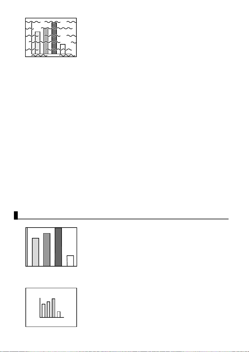
4.2 Enlarging an Image
The remote control included lets you enlarge portions of an image.
1.
Press the E-Zoom butt on on the rem ote
control to enlarge or reduce the display on
screen.
Reduction Enlargement
Magnification factor is displayed.
(The Esc button releases this feature.)
Point:
24-step partial enlargement and reduction by
factors of 1x-4x is ava ilable.
2.
Push the Enter button in any direction to
scroll in that direction.
40
Push up
Push rightPush left
Push down
Page 43
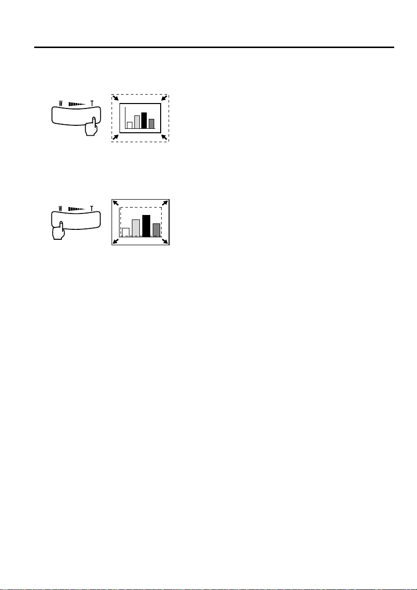
4.3 Adjusting Imag e Size
The Wide/Tele button on the projector allows you to adjust the size of images.
1.
When you press the right side of the button
(Tele), images are reduced.
2.
When you press the left side of the button
(Wide), images are enla rged.
Point:
• The enlargement/red uction range that the Tele
and Wide buttons provide is from 0.8x to 1.0x
in 32 steps.
• This function is active until th e Reset All menu
is executed (see page 55).
41
Page 44

4.4 Adding Image Effects
Using the Effect1 and Effect2 buttons, you can add effects to images during
presentation (to cancel this function, press the Esc button).
For effects settings, see "5.4 Effect Menu" (page 50).
Cursor/Stamp
This effect displays a cursor on the screen and freezes it at a desired location.
1.
Press the Effect1 button to display a cursor.
2.
Use the Enter button to move the cursor to a
desired location.
3.
Press the Enter button, and the cursor
position is displayed as a stamp.
Point:
• To remove the cursor stamp display, activate a
horizontal bar .
• To remove the stamp, press the Effect3 button.
Horizontal Bar
This effect displays a horizont al line on the s creen and al lows you to move i t up
or down by remote control.
1.
Press the Effect2 button to display a
horizontal bar.
2.
Move the Enter button up or down to move
the horizontal bar up or down.
Point:
• To remove the horizontal bar, activate the
cursor/stamp.
42
Page 45

4.5 Freezing and Dele ting Images
Freezing a Moving Image (Remote Control Only)
You can freeze a moving image (video or other image).
1.
Press the Freeze button on the remote
control.
(To release the freeze, press the Freeze
button again.)
Muting Images and Sound (Remote Control Only)
You can temporarily mute images and sound and project a black or blue image.
1.
Press the A/V Mute button on the remote
control.
(To cancel the muting featu re, press the A/V
Mute button or another button.)
Point:
Using the Setting > A/V Mute menu, you can
change the color (black, blue) of the image
projected when audio and video have been
muted (see page 52).
43
Page 46

4.6 Displaying Help Screens
You can display topic-specific help on screen for solving problems. Use this
function when problems occur.
1.
Press the Help button to start the help
function.
(Press the Help button again to cancel this
function.)
Point:
If you cannot solve your problem using the Help
function, consult the "Troubleshooting" section
in this manual (see page 57).
2.
Use the Select button on the projector to
select a topic (on the remote cont rol , u se the
Enter button).
44
3.
Press the Enter button to enter your
selection.
4.
Select a detailed topic as de scribed in steps 2
and 3 and follow the instructions displayed.
Page 47

Menu Functions
5
(Remote Control Only)
5.1 Learning Basic Operations............................46
5.2 Video Menu...................................................47
5.3 Audio Menu ..................................................49
5.4 Effect Menu...................................................50
5.5 Setting Menu .................................................51
5.6 Advanced Menu ............................................53
5.7 About Menu ..................................................54
5.8 Reset All Menu .............................................55
45
Page 48
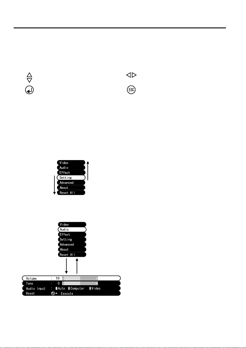
5.1 Learning Basic Operations
This section presents the basic functions available in menus.
For functions in each menu, access the guide available under each menu.
[Explanation of symbols]
: Push the Enter button t o the upper
or lower side.
: Press the Enter button. : Press the Esc button.
: Push the Enter button to the left or
right side.
[Opening and Closing Menus]
Press the Menu button to display the top menu.
To close this menu, press the Menu button again.
When the Menu button is pressed to close the top menu, the status at close
will be maintained.
[Menu Selection]
Push the Enter button to the upper or
Push the
Enter button
to the lower
side.
Push the
Enter button
to the upper
side.
lower side to move the menu up or
down.
[Moving in Hierarchy Structure Sub-menu selection]
Press the Enter button to move to the
sub-menus.
Press the Esc button to return to the
top menu.
Press the Menu button to clear the
Press Enter Press Esc
menu display.
46
Page 49
5.2 Video Menu
Displaying Menus
Press the Menu button, use the Enter button to select "Video" from the top
menu displayed, and press the Enter button to move to a submenu.
Point:
• When there is no video signal from a computer or component video device, the
"Video" menu is not available for settings.
• When there is no video signal from a video device, only the "Mod e" men u is a vailab le
for settings.
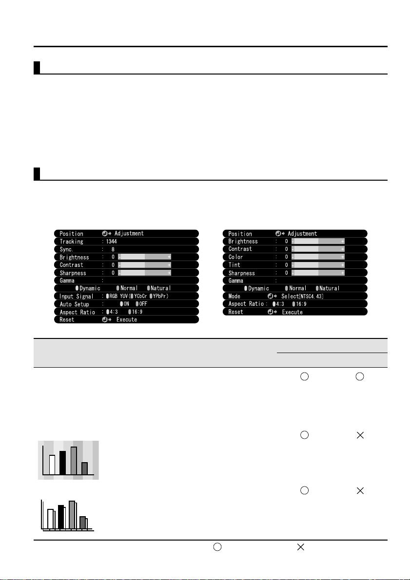
Settings
Video menu elements to be set differ as follows when projecting computer/
component video versus video images.
Computer/Component Video Projection Video Projection
D-Sub15: Computer/Component video Video: Video image
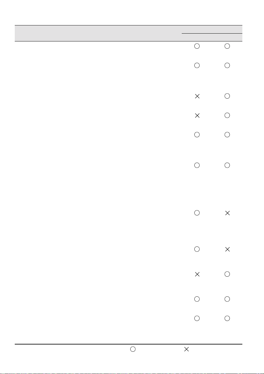
Menu Content
Position Adjust video position vertically and
horizontally.
* After position is adjusted, c hanges in the
video signal from a computer (such as
changes in output mo de or display color)
may change the adjusted value.
Tracking Adjust when broad vertical streaks appea r
in image.
(Available for setting only when input
signal is RGB).
Sync. Adjust when flickering or blurring occurs
(available for setting only when input
signal is RGB).
* When tracking is wrong, adjustment of
sync will not correct flickering. Always
adjust tracking before adjusting sync.
: setting available : setting not available
Video Projection
D-Sub15 Video
47
Page 50
D-Sub15: Computer/Component video Video: Video image
Menu Content
Brightness Adjusts image brightness.
+: Brightens image.
- : Darkens image.
Contrast Adjusts difference in color brightness/darkness.
+: Increas es difference in color brightness/
darkness.
- : Decreases difference in color brightness/
darkness.
Color Adjusts color depth.
+: Deepens color.
- : Lightens color.
Tint Adjusts tint.
+: Strengthens red.
- : Strengthens green.
Sharpness Adjusts image sharpness.
+: Strengthens sharpness and defines image.
- : Weakens sharpness and softens image.
* If keystone correction makes unevenness
distinctive, reduce the sharpness.
Gamma Adjusts color of projected image.
Dynamic: Increases contrast. (Used when
projecting images c on t ai nin g t ext and
graphics)
Normal : Sets normal contrast.
Natural : Weakens contrast to natural colors.
(Used to give projected images a
more natural look)
Input Signal Select the input signal of the computer/
component video in use.
RGB:Computer images
YUV:Color difference images
YCbCr:DVD images
YPbPr:HDTV images
Auto Setup Optimizes computer input image.
(Can only be set when the input signal is RGB)
ON : Auto Setup active
OFF: Auto Setup not active
Mode Select the video mode to use.
* Selection of Au to provides automatic v ideo
signal identifica tion , but for PAL (60Hz) mode ,
set to Manual.
Aspect Ratio Select the aspect ratio.
(Can only be set when projecting a component
video image (YCbCr, YPbPr).)
Reset Returns Vide o menu setti ngs to factory shipping
values.
* See page 56 for factory shipping values.
To reset all menus to factory shipping values,
use the "Reset All" menu.
: setting available : setting not available
Video Projection
D-Sub15 Video
48
Page 51

5.3 Audio Menu
Displaying Menus
Press the Menu button, use the Enter button to select "Audio" from the top
menu displayed, and press the Enter button to move to a submenu.
Settings
Menu Content
Volume Adjusts the volume of sound output from the projector.
Tone Adjusts the tone of sound output from the projector.
Audio Input Select an audio input destination.
Reset Returns Audio menu settings to factory shipping values.
+: Increases volume.
- : Decreases volume.
+: Increases treble.
- : Decreases treble.
(When the input signal is a component video signal, select Video.)
Auto : Audio input matching that of the displayed video is
selected.
(Example: When computer video is displayed, computer
audio input is selected).
Computer : Audio input from computer is selected.
Video : Audio in put from an A/V device is selected.
* See page 56 for factory shipping values.
To reset all menus to factory shipping values, use the Reset All
menu.
49
Page 52

5.4 Effect Menu
Displaying Menus
Press the Menu button, use the Enter button to select "Effect" from the top
menu displayed, and press the Enter button to move to a submenu.
Settings
Menu Content
Cursor/Stamp Make detailed settings for the cursor/stamp function assigned to the
Horizontal Bar Make detailed settings for the horizontal bar function assigned to the
Cursor Speed Set the cursor speed.
Reset Returns Effect menu settings to their factory shipping values.
remote control Effect1 button.
Shape : Select the shape of the cursor/stamp .
Zoom Rate : Select the display zoom factor for the cursor/stamp.
remote control Effect2 button.
Color : Select the horizontal bar color.
Width : Select the width of the horizontal bar from 2-20 dots (in
2-dot steps).
L:Low
M : Medium
H:High
* See page 56 for factory shipping values.
To reset all menus to factory shipping values, use the Reset All
menu.
50
Page 53

5.5 Setting Menu
Displaying Menus
Press the Menu button, use the Enter button to select "Setting" from the top
menu displayed, and press the Enter button to move to a submenu.
Settings
Menu Content
Keystone If the screen is distorted i n t rapezoidal form, adju st it t o n orm al dis pl ay .
-: Broadens upper screen
* • You can also adjust the screen with the Keystone button on the
projector.
• A keystone correction reduces screen size.
• The keystone correction is stored in memory. You will need to
readjust the image if the projection angl e is chan ge d.
• If a keystone correction makes the image noticeably uneven,
reduce the video sharpness with the menu commands Video >
Sharpness.
No-signal/Msg Set the screen display when there is no video signal.
OFF : No message is displayed. (Screen displays black.)
Black : "No-signal" is displayed on a black background (when the
language is English).
Blue : "No-signal" is displayed on a blue background (when the
language is English).
Prompt Set whether the input source currently selected is displayed/not
displayed on the screen.
ON : After input source switching, the input source is displayed for
approximately 3 seconds.
+: Broadens lower screenNormal screen
OFF: The input source is not displayed.
51
Page 54

Menu Content
A/V Mute*
(See page 74)
Sleep Mode After sleep mode is activ ated, the projector enters s tandby mode when
Reset Returns Setting menu settings to their factory shipping values.
Temporarily eliminates video during a presentation in order to focus
attention on the present er or elsewhe re. Press the A/V Mu te button to
use this function.
Black : A black screen is displayed.
Blue : A blue screen is displayed .
no signal is inpu t from an ex ternal sourc e for a conti nuous perio d of 3 0
minutes.
ON : Sleep Mode active
OFF: Sleep Mode inactive
* See page 56 for factory shipping values.
To reset all menus to factory shipping values, use the Reset All
menu.
52
Page 55

5.6 Advance d Menu
Displaying Menus
Press the Menu button, use the Enter button to select "Advanced" from the top
menu displayed, and press the Enter button to move to a submenu.
Settings
Menu Content
Language Select the menu language.
Color Setting Use color temperature or RGB to create settings for the colors displayed
Rear Proj. This setting is used for projection from the rear of a screen.
Ceiling This setting is used for projection with the projector hanging from a
Reset Returns Advanced menu settings to their factory shipping values.
Select from Japanese, English, German, French, Italian, Spanish,
Portuguese, Chinese and Korean.
on screen.
Color Temp:Adjusts the color temperature of the video.
Select "Color Temp" and press the Enter button to create
settings.
The setting unit is Kelvins (K).
+ : Increases color temperature (strengthens blue).
- : Decreases color temperature (strengthens red).
RGB: Adjusts red, green, and blue intensity.
Select "RGB" and press the Enter button to create settings.
+ : Strengthens color.
- : Weakens color.
ON : Inverts a projected image vertically.
OFF: Restores original .
ceiling.
ON : Inverts a projected image vertically and horizontally.
OFF: Restores original .
* See page 56 for factory shipping values.
To reset all menus to factory shipping values, use the Reset All menu.
53
Page 56
5.7 About Menu
Displaying Menus
Press the Menu button, use the Enter button to select "About" from the top
menu displayed, and press the Enter button to move to a submenu.
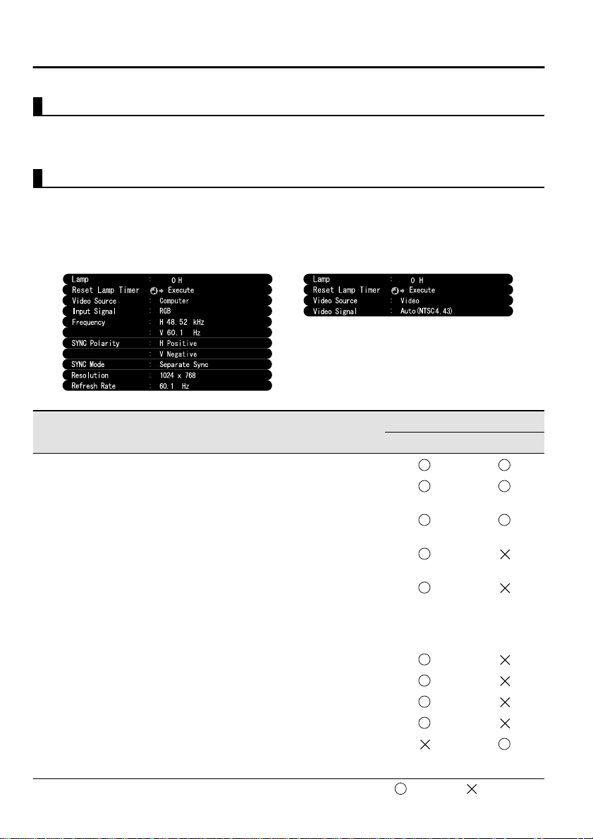
Setting and Display Information
The settings information displayed in the About menu differs as shown below
during video projection from a computer/component versus a video device.
Computer/Component Video Projection Video Projection
D-Sub15: Computer/Component video Video: Video image
Menu Content
Lamp Displays cumulative lamp-on time.
Reset Lamp
Timer
Video Source Displays the source for the video
Input Signal Displays a computer/component video
Frequency Displays frequencies.
SYNC Polarity Displays sync pola rity.
SYNC Mode Displays sync attr ibutes.
Resolution Displays input resolution.
Refresh Rate Displays refresh rate (vertical frequency).
Video Signal Displays an A/V device signal mode.
Sets cumulative lamp-on time to zero.
Use this function when replacing the lamp.
displayed on screen.
input signal.
H: Displays the horizontal scanning
frequency.
V: Displays the vertical scanning
frequency.
(When set to Auto in the menu, "Auto
(NTSC)" is displayed.)
54
Video Projection
D-Sub15 Video
: Display : No display
Page 57

5.8 Reset All Menu
Displaying Menus
Press the Menu button, and use the Enter button to select "Reset All" from the
top-level menu displayed.
Settings
Menu Content
Reset All Returns all menu settings to initial settings.
(Lamp and language settings excluded)
* Note that rear and invert settings will also be cleared by this
operation.
55
Page 58
Initial Settings List
Initial settings at product shipment are shown below.
Main Menu Title Submenu Title Initial Settings
Video (Computer/
Component Video)
Video (Video) Position
Audio Volume
Effect Cursor/Stamp
Position Central value
Tracking Dependent on the connected signal
Sync. 0
Brightness
Central valueContrast
Sharpness
Gamma Normal
Input Signal RGB
Auto Setup ON
Aspect Ratio 4:3
Brightness
Contrast
Color
Tint
Sharpness
Gamma Normal
Mode Auto
Aspect Ratio 4:3
Tone
Audio Inpu t Auto
Shape: Zoom Rate: 100%
Central value
Central value
Horizontal Bar Color: Magenta Width: 2
Cursor Speed M
Setting Keystone Central value
No-Signal Msg Blue
Prompt ON
A/V Mute Black
Sleep Mode OFF
Advanced Language
Color Setting Color Temp, (Computer/Component
Rear Proj.
Ceiling
video: 7500K, Video: 6700K)
OFF
56
Page 59

6
Troubleshooting
6.1 Possible Failures............................................58
6.2 When Indicators Do Not Help.......................60
57
Page 60

6.1 Possible Failures
If you think your projector may have failed, first check the indicators on the
unit.
Your projector includes an "operation display indicator" and a "problem/alarm
display indicator" which provide information on projector status.
Problem/Alarm Display Indicator
Operation Display Indicator
Operation Display Indicator
Indicator
Status
Steady
orange
Flashing
orange
Steady
green
Flashing
green
Not lit No power If the lamp has been replaced, check that the lamp
Cause Remedy or Status
Standby
status
Cool-down
in progress
Projection
in progress
Warm-up in
progress
(Not abnormal)
Press the Power button to begin projection.
(Not abnormal)
Please wait.
Cool-down* time takes about 2 minutes. (see page
74).
You cannot operate the Power button during cool-
down. Press the button again after cool -down ends.
(Not abnormal)
(Not abnormal)
Please wait.
Warm-up time is approximately 30 seconds.
After warm-up is complete, the flashing green
indicator changes to steady green.
and lamp cover are attached securely.
Check the power cord connectio ns. 28
Check power at the outlet. 28
See
Page
28
35
29
29
68
58
Page 61

Problem and Alarm Display Indicator
Indicator
Status
Steady red High
Flashing
red
(1-second
intervals)
Flashing
red
(2-second
intervals)
Flashing
orange
Cause Remedy or Status
internal
temperature
Problem
with lamp
Internal
problem
High-speed
cooling in
progress
See
Page
The usage temperature range of the projector is
5°C–35°C, and the projector should be used in this
range.
Place the projector in a well-ventilated location
where air intake and exhaust vents are not blocked.
Clean the air intake vent. 67
While the indicator is red, turn off the lamp to lower
the internal temperature of the projector.
Replace with new lamp.
Model No: ELPLP13
If the lamp is broken, handle pieces carefully to
avoid injury, and consult an Epson Service Center
for repair (video cannot be projected until the lamp
is replaced).
If the lamp or lamp cover is not attached securely,
follow the replacement instructions to attach it
securely.
Stop using the projector, pull the plug from the
outlet, and consult your vendor or an Epson Service
Center (listed at the end of this manual) for repair.
Not a problem, but projection will be interrupted
automatically to prevent further temperature rise.
The usage temperature range of the projector is
5°C–35°C, and the projector should be used in this
range.
Place the projector in a well-ventilated location
where air intake and exhaust vents are not blocked.
Clean the air intake vent. 67
77
18
68
68
77
18
-
-
-
-
Point:
• If the indicator is normal but you experience problems with video projection, refer to
"When Indicators Do Not Help" on the following page.
• If the indicator display status is not shown in this table, consult your vendor.
59
Page 62

6.2 When Indicators Do Not Help
Video is Not Projected
[Nothing is Displayed]
• Is the lens cover still on? See page 28
Have you turned the power off and then immediately
•
on? See page 35
The Power button cannot be operated immediately after
the projection has been switched off. The Power button
becomes operable after cool-down* is complete (See
No Display
[A Message Appears]
Display shows
"Not Supported".
Display shows "NoSignal".
60
page 74) .
Is Sleep Mode on? See page 52
•
If Sleep Mode is set to on and no vi deo sign al is in put for
30 minutes, the projector lamp shuts off automatically.
• Is video brightness adjusted correctly? See page 48
• Is "A/V Mute" mode active? See page 52
• Is the computer's screen saver on or is the computer
in power save mode?
• Is the resolution of the video signal output from your
computer higher than SXGA (1280x1024)?
See page 23
Check that the frequency of the video signal output
•
from your computer is a compatible mode.
See page 23
Consult your computer instruction manual for any
changes to be made to the resolution or frequency of the
video signal output from your computer.
• Are the cables connected correctly? See pages 24, 25
Have you correctly selected the video input terminal
•
connected? See page 30
Press the Source button on the projector (Computer,
Video, or S-Video on the remote control) to switch the
video source.
• Is power provided to a connected computer or A/V
device? See page 30
• Is a video signal output from a connected computer or
A/V device?
When using a notebook computer or integrated LCD-
•
type computer, a video signal must be output to the
projector. See page 31
A video signal is normally output only to an LCD screen,
not externally. Switch th e video si gnal t o extern al output.
Some computer models do not display video on an LCD
Page 63

Image is Unclear
Blurry image
•
Image only partially
•
focused
Not focused at all
•
screen even when a video signal is output externally.
Carefully review sections such as "Providing External
Output" and "Providing Output to an Externally
Connected Monitor" in the instruction manual of the
connected computer.
•Is the focus adjusted correctly? See page 33
Is the projection distance optimal? See page 20
•
The recommended projection distance is 1.0m
(39.37inches) to 13.1m (515.75inches) . Set up the
projector in this range.
•Is the lens dirty? See page 66
•Is the projection beam facing the screen directly?
See page 18
Is the lens covered with condensation?
•
If you carry the projector from a cold room into a warm
room, the lens may become covered with condensation
and the image may be blurred. After a short period, the
image should return to normal.
•Press the Auto button on the remote control.
See page 34
Have you adjusted Sync.*, Tracking*, and Position?
•
See page 47, 74
Use the menu to adjust.
Are the video signal mode settings correct?
•
See page 48
Use the Menu > Video > Mode menu items to select a
video signal format. Auto detection according to video
signal input is not always possible.
Are the computer/component video signal settings
•
correct? See page 48
Select the correct input signal se tti ngs b y se lecting Menu
> Video > Input Signal.
RGB: Computer images
YUV: Color difference images
YCbCr: DVD images
YPbPr: HDTV images
61
Page 64
Disturbed image
•
Noisy
•
• Are cables connected correctly? See pages 24, 25
Is the correct resolution selected? See page 23
•
Set your computer to provide a signal compatible with
the projector. Consult your comp ut er instruct i on manu al
with regard to modifying the signal.
• Press the Auto button on the remote control.
See page 34
Have you adjusted Sync.*, Tracking*, and Position?
•
See page 47, 74
Use the "Menu" to adjust.
Are the video signal mode settings correct?
•
See page 48
Use the Menu > Video > Mode menu items to select a
video signal format. Auto detection according to video
signal input is not always possible.
Are the computer/component video signal settings
•
correct? See page 48
Select the correct i nput sign al set tings by selecting Menu
> Video > Input Signal.
RGB: Computer images
YUV: Color difference images
YCbCr: DVD images
YPbPr: HDTV images
• Are you using an cable included or one sold
separately? See page 72.
Are cables too long?
•
A commercial video signal amplifier shoul d be used with
computer cables longer than 10m (393.70inches) .
Image Disappears or is Undersized
Have you adjusted "Position"? See page 47
•
Use the Menu > Video > Position menu items to adjust.
Is the correct resolution selected? See page 23
•
Set your computer to provide a signal compatible with
the projector. Consult your comp ut er instruct i on manu al
with regard to modifying the signal.
Change the resolution of your notebook type or
Image Disappears
•
Undersized
•
•
integrated LCD-type computer. See page 31
Change the resolution to provide a full LCD display, or
provide the video signal only to the external output.
62
Page 65

Image Color is Poor
• Is image brightness adjusted correctly? See page 48
•Are cables connected correctly? See pages 24, 25
•Is contrast* adjusted correctly? See pages 48, 74
•Is color adjusted correctly? See page 53
•
•
•
Images Are Dark
•
• Is image brightness adjusted correctly? See page 48
•Is contrast* adjusted correctly? See pages 48, 74
Are color depth and tint adjusted correctly?
See page 48
(Video tint and display to a computer monitor or LCD
may not match, but this is not abnormal.)
Does the lamp need replacement? See page 68
A nearly expired lamp can produce dark images or poor
tint and should be replaced with a fresh lamp.
Are the computer/component video signal settings
correct? See page 48
Select the correct input signal se tti ngs b y se lecting Menu
> Video > Input Signal.
RGB: Computer images
YUV: Color difference images
YCbCr: DVD images
YPbPr: HDTV images
Does the lamp need replacement? See page 68
A nearly expired lamp can produce dark images or poor
tint and should be replaced with a fresh lamp.
There is No Sound
•Are audio inputs connected correctly? See page 24
•Are audio outputs connected correctly? See page 27
•Have you selected the video whose audio you wish to
output? See page 30
s volume adjusted to the minimum level? See page
•I
34
Is the A/V Mute function on? See page 52
•
The A/V Mute mode may also be active.
Press the Volume button to release the A/V Mute.
Is the audio input setup correct? See page 49
•
Select the correct audio signal by selecting Menu >
Audio > Audio Input.
63
Page 66
The Remote Control Does Not Operate
• Is the remote control R/C On Off switch set to On?
See page 29
Are you pointing the remote control in the correct
•
direction for operation? See page 15
The range of operation is approximately 30° left or right
and approximately 15 ° above or below th e remote contro l
sensor on the projector.
Is the remote control too far from the projector?
•
See page 15
The operable distance is approximately 10m
(393.70inches).
• Is the remote control receiver on the projector
blocked?
• Is the remote control receiver in the path of direct
sunlight or strong fluorescent light?
• Are batteries in place? See page 16
• Are the batteries worn? See page 16
• Are the batteries inserted correctly? See page 16
Cannot Switch off (After Pressing the Power Button)
The operation display indicator remains a steady
OFF
•
orange.
The operation display indicator of the projector is
designed to remain lit even after power is switched off.
When the plug is pulled out of the outlet, the operation
display indicator will go out.
The fan does not stop.
•
After the Power button is pressed and power is turned off,
cool-down* begins. See page 74
After cool-down, the operation display indicator lights
orange, and you should pull the plug out of the outlet.
* Cool-down time varies depending on the external
temperature and other factors.
64
Page 67

7
Maintenance
7.1 Projector Cleaning, Lens Replacement,
Air Intake Vent Cleaning ..............................66
7.2 Lamp Replacement........................................68
65
Page 68

7.1 Projector Cleaning, Lens Replacement,
Air Intake Vent Cleaning
Clean your projector when it is dirty or image projection is poor. Clean the air
intake vent every 100 hours in practice.
Warning:
• No one but trained service personnel should open the projector cabinet. The
projector contains several high voltage components which can cause electric shock.
For internal repairs, maintenance, and cleaning, take your projector to your vendor
or an Epson Service Center.
• Use care when handling the power plug and connector. Improper handling may
cause fire or electric shock. When handling the plug, observe the following.
· Do not insert a plug or connector into an outlet or terminal if it is dirty or holds
foreign matter.
· Insert the plug and connector firmly and completely.
· Do not pull out the plug or connector with wet hands.
Caution:
• Never attempt to remove the lamp immediately after use.
· Heat may cause burns or other injury.
· Wait approximately 60 m inutes af ter switc hing of f power and remo ve the la mp after
the projector has cooled completely.
• When performing operations, pull the pow er p lug an d connector out of the outlet and
terminal respectively.
Switch off power to the projector and disconnect the power cord before
cleaning.
Cleaning the Projector Unit
•Wipe dirt from the projector lightly with a soft cloth.
•For heavier dirt, wipe the projector lightly with a cloth soaked in a weak
solution of mild detergent and wrung out thoroughly, t hen dry with a separate
cloth.
Do not use waxes, benzene , thinners, or other volat il e substances. These may
degrade the cabinet or strip the finish.
Cleaning the Lens
Clean the lens with a commercial blo wer or lens cleaning paper. Th e surface of
the lens is easily scratched and should not be rubbed or struck with hard
objects.
66
Page 69
Cleaning the Air Intake Vents
Accumulated dust in the air intake vents degrades ventilation, increases the
interior temperature, and can cause malfunction.
To prevent debris from enter ing the a ir int ake vent s, al ways stand the projector
upright with the lens upward. Then use a vacuum cleane r or other equipment to
suck dust from the vents.
Point:
If it is no longer possible to remove the di rt from the ai r intake ve nt, it is ti me to
replace it. Consult your vendor.
67
Page 70
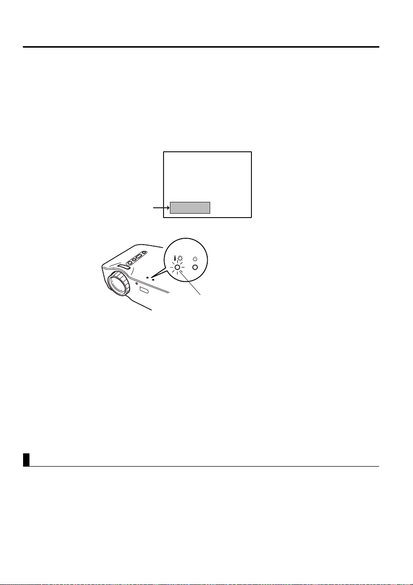
7.2 Lamp Replacement
Replace the lamp with a new lamp in the following instances.
A replacement lamp is an optional part (sold separately).
(Model No: ELPLP13)
[When the following message is displayed for 30 seconds after projection
begins: "Lamp Replace. After the replacement of the lamp, reset the lamp
timer under the direction in the user’s manual."]
A message will be displayed.
[When the problem/alarm display indicator flashes red at 1-second intervals.]
Problem/alarm display indicator
flashes red at 1-second intervals
[When brightness or picture quality is inferior to its original state.]
Point:
• If the lamp does not light, replace it even if the lamp life has not expired.
• To maintain the original brightness and picture quality, replace the lamp as soon as
possible after a replacement message appears.
• To maintain the original brightness and picture quality, replacement messages are set
for approximately 1,400 hours.
• Though a replacement message appears at approximately 1,400 hours, individual
lamp characteristics or usage conditions may cause failure before 1,400 hours, and
we recommend that a replacement lamp be kept on hand.
• A replacement lamp can be purchased from your local Epson product vendor.
Replacement
Point:
• Install the lamp securely. For safety, when the lamp cover is opened, the abnormal
warning display indicator flashes red, and the projector lamp goes out. If the lamp or
lamp cover is installed improperly, the lamp will not light.
68
Page 71
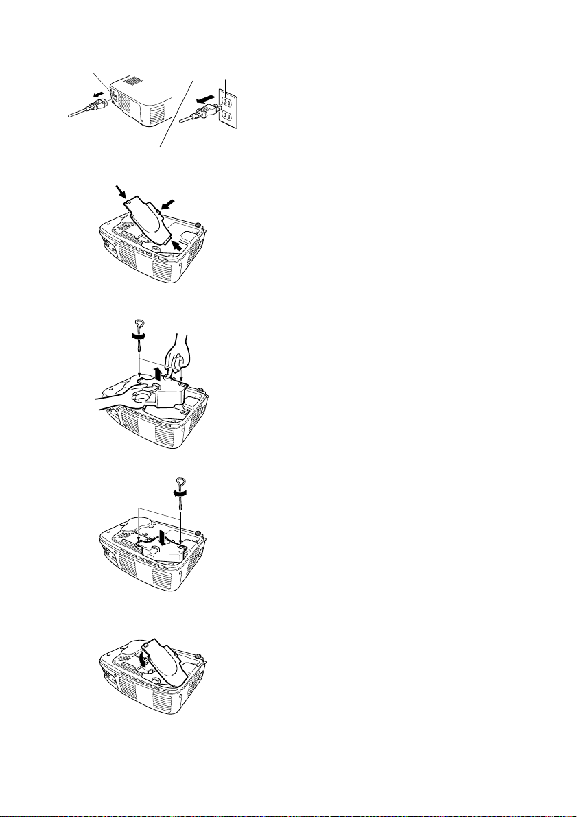
Power terminal
Wall outlet
Power cord
1.
Switch off power to the projector and
disconnect the po wer cor d after cool-down*
ends (see page 74).
Cool-down time varies ac cording to externa l
temperature and other factors.
2.
After the projector has cooled completely,
remove the lamp cover.
•The projector requires approximately 60
minutes to cool completely.
•Press on the 2 catches and pull the cover
out diagonally.
3.
Pull the lamp out.
Use a screwdriver to loosen the two lam p
retaining screws, then grasp the holds and
pull the lamp out.
4.
Install a new lamp.
Align the lamp properly, insert the lamp
until it contacts the rear of the housing, and
use a screwdriver to tighten the two lamp
retaining screws firmly.
5.
Install the lamp cover.
Insert the cover diagonally and press it into
the projector un til you hea r the ca tches click
into place.
Check that the catches ar e securely fastened.
Point:
After lamp replacement, use the About menu to
reset lamp time to its initial value (see page 54).
69
Page 72

70
Page 73

8
General Notes
8.1 Optional Parts................................................72
8.2 Shipping Instructions ....................................73
8.3 Glossary.........................................................74
8.4 Index..............................................................75
8.5 Specifications................................................77
8.6 External Dimensions.....................................78
8.7 International Warranty System .....................79
71
Page 74

8.1 Optional Parts
The accessories shown bel ow are ava ilabl e. Purcha se thes e as your applic ation
requires.
• Replacement Lamp (ELPL P13)
Recommended for purchase before lamp
life expires (screwdriver included).
• Portable screen
50 inch screen: ELPSC06
60 inch screen: ELPSC07
80 inch screen: ELPSC08
• RGB extension cable
ELCCB05: 5m
ELCCB10: 10m
Use if the computer ca ble included is n ot
long enough.
(For mini D-sub 15-pin/mini D-sub 15pin)
• Soft carrying case
(ELPKS16, ELPKS24)
Used for projector transport.
• PC selector (ELPST01)
Use when multiple RGB signal sources
are being used.
• Image Presentation Viewer
(ELPDC01, ELPDC02, ELPDC03)
For use with paper, OHP copy, or in slide
projection.
• Computer Cable
ELPKC02: 1.8m
ELPKC09: 3.0m
ELPKC10: 20m
Use if the computer ca ble in clude d is not
long enough.
(For mini D-sub 15-pin/mini D-sub 15pin)
• Mac Adapter Set (ELPAP01)
For use in connecting the projector to a
Macintosh computer.
• Component Video Cable
(ELPKC19: 3.0m)
(For Mini D-Sub 15-pin/RCA)
• D terminal cable
(ELPKC22: 3.0m)
(For D-sub 15/D terminal)
72
Page 75

8.2 Shipping Instructions
Your projector includes numerous glass and precision components. When
shipping your projector, treat it as follows to prevent malfunction caused by
impacts.
Shipping to the Manufacturer for Repair
• Use the original shipping box.
• If you do not have the original shipping box, protect your projector against
transmitted impacts by wrapping it in a shock-absorbing material and
placing it in a strong cardboard box.
Hand-Carrying
• Use a soft carrying case (Model No: ELPKS16 or ELPKS24).
• During air travel, carry the projector on-board as hand luggage.
* Purchasers should bear in mind that the warranty does not apply to any malfunction
arising during transportation.
73
Page 76

8.3 Glossary
This glossary provides brief explanations of terms which are used in this
manual but are not explained in the text or difficult to understand. For details,
refer to other available publications.
Term Description
A/V Mute Refers to temporary stoppage of audio and video. Your projector
SVGA Refers to a 800-pixel (Pix) horizontal x 600-pixel (Pix) vertical
SXGA Refers to a 1280-pixel (Pix) horizontal x 1024-pixel (Pix) vertical
Sync
(synchronization)
USB An abbreviation for universal serial bus, an interface for connecting
VGA Refers to a 640-pixel (Pix) horizontal x 480-pixel (Pix) vertical
XGA Refers to a 1024-pixel (Pix) horizontal x 768-pixel (Pix) vertical
Cool-Down After the Power button is pressed and the lamp goes out, lamp
Contrast The enhancing or weakening of differences in color lightness and
Tracking Signals output by a computer are out put at a certain pre determi ned
provides this function when the A/V Mute button is pressed. When
the A/V Mute button is pressed again or audio volume is adjusted,
this function is released.
display signal for an IBM PC/AT-compatible (DOS/V) computer.
display signal for an IBM PC/AT-compatible (DOS/V) computer.
Signals output by a computer are output at a certa in predete rmine d
frequency.
If the frequency of your projector cannot match that frequency, a
clear image cannot be obtained. Matching of signal phases (peak
offset) is referred to as synchronization (synch).
If synchronization is not achieved, a projected image displays
jitters, blurring, and horizontal noise.
a personal computer with a relatively low-speed peripheral device.
display signal for an IBM PC/AT-compatible (DOS/V) computer.
display signal for an IBM PC/AT-compatible (DOS/V) computer.
cooling is continued. After the lamp goes out, a cooling fan spins,
and operational buttons become inactive.
Cool-down time takes about 2 minutes.
darkness that provides a sharper or softer view of characters and
images. This adjustment is referred to as contrast adjustment.
frequency.
If the frequency of your projector cannot match that frequency, a
clear image cannot be obtained. Matching of signal frequencies is
referred to as matching tracking. When tracking is not matched, a
projected image displays broad vertical bands.
74
Page 77

8.4 Index
[A]
A/V Device . . . . . . . . . . . . . . 25
A/V Mute . . . . . . . . . . . . . . . . 52
A/V Mute Button . . . . . . . 14, 43
About Menu . . . . . . . . . . . . . . 54
Adjusting . . . . . . . . . . . . . 32, 34
Advanced Menu . . . . . . . . . . . 53
Air Intake Vent . . . . . . . . . . . 12
Aspect Ratio . . . . . . . . . . . . . 48
Audio In Terminal . . . . . . 13, 24
Audio Input . . . . . . . . . . . . . . 49
Audio Menu . . . . . . . . . . . . . . 49
Audio Out Terminal . . . . . 13, 27
Auto Button . . . . . . . . . . . 14, 34
Auto Setup . . . . . . . . . . . . . . . 48
[B]
Battery Cover . . . . . . . . . . 14, 16
Brightness . . . . . . . . . . . . . . . 48
[C]
Ceiling . . . . . . . . . . . . . . . . . . 53
Color . . . . . . . . . . . . . . . . . . . 48
Color Setting . . . . . . . . . . . . . 53
Compatible Mode . . . . . . . . . 23
Computer . . . . . . . . . . . . . . . . 22
Computer Button . . . . . . . 14, 30
Computer Terminal . . . . . 13, 24
Connecting . . . . . . . . . . . . 24, 25
Contrast . . . . . . . . . . . . . . . . . 48
Cursor Speed . . . . . . . . . . . . . 50
Cursor/Stamp . . . . . . . . . . 42, 50
[E]
Effect Button . . . . . . . . . . 14, 42
Effect Menu . . . . . . . . . . . . . . 50
Enter Button . . . . . . . . 14, 38, 46
Esc Button . . . . . . . . . 14, 38, 46
External Audio Device . . . . . .27
External Dimensions. . . . . . . . .78
E-Zoom Button . . . . . . . . .14, 40
[F]
Focus Ring . . . . . . . . . . . . .12, 32
Foot Lever . . . . . . . . . . . . . . . .12
Freeze Button . . . . . . . . . . .14, 43
Frequency . . . . . . . . . . . . . . . .54
Front Foot . . . . . . . . . . . . .12, 32
[G]
Gamma . . . . . . . . . . . . . . . . . . .48
[H]
Help Button . . . . . . . . .13, 14, 44
Help Screens . . . . . . . . . . . . . .44
Horizontal Bar . . . . . . . . . .42, 50
[I]
Indicator . . . . . . . . . . . . . . . . . .14
Initial Settings . . . . . . . . . . . . .56
Input Signal . . . . . . . . . . . .48, 54
Input/Output Terminals . . . . . .12
Inserting Batteries . . . . . . . . . .16
[K]
Keystone . . . . . . . . . . . . . . . . .51
Keystone (Select)
Button . . . . . . . . . . . . . . . .13, 33
[L]
L/R Audio Terminals . . . . .13, 25
Lamp . . . . . . . . . . . . . . . . . . . .54
Lamp Cover . . . . . . . . . . . . . . .12
Lamp Replacement . . . . . . . . .68
Language . . . . . . . . . . . . . . . . .53
Lens Cover . . . . . . . . . . . . . . . .12
75
Page 78

[M]
Mac Mouse Cable . . . . . . . . . 39
Macintosh . . . . . . . . . . . . . . . 39
Menu Button . . . . . . . . . . 14, 46
Mode . . . . . . . . . . . . . . . . 48, 54
Mouse Cable . . . . . . . . . . . . . 39
Mouse/Com Terminal . . . 13, 39
[N]
No-signal . . . . . . . . . . . . . . . . 51
Notebook . . . . . . . . . . . . . . . . 31
[O]
Operating Panel . . . . . . . . . . . 12
Operation Display
Indicator . . . . . 12, 28, 29, 35, 58
Optional Parts . . . . . . . . . . . . 72
[P]
Position . . . . . . . . . . . . . . . . . 47
Power Button . . . . 13, 14, 29, 34
Power Cord . . . . . . . . . . . . . . 28
Power Terminal . . . . . . . . 12, 28
Problem/Alarm Display
Indicator . . . . . . . . . . . 12, 59, 68
Projection Distance . . . . . . . . 20
Prompt . . . . . . . . . . . . . . . . . . 51
PS/2 Mouse Cable . . . . . . . . . 39
[R]
R/C On Off Button . . . 14, 29, 36
Rear Foot . . . . . . . . . . . . . . . . 12
Rear Projection . . . . . . . . . . . 53
Refresh Rate . . . . . . . . . . . . . . 54
Remote Control . . . . . . . . 14, 15
Remote Control Receiver . . . 12
Reset . . . . . . . 48, 49, 50, 52, 53
Reset All Menu . . . . . . . . . . . 55
Reset Lamp Timer . . . . . . . . . 54
Resolution . . . . . . . . . . . . . . . 54
[S]
Screen Size . . . . . . . . . . . . . . . 20
Setting Menu . . . . . . . . . . . . . 51
Setup Instructions . . . . . . . . . 19
Sharpness . . . . . . . . . . . . . . . . 48
Shipping Instructions . . . . . . . 73
Sleep Mode . . . . . . . . . . . . . . 52
Source (Enter) Button . . . 13, 30
Speaker . . . . . . . . . . . . . . . . . 12
Special Notes on Setup . . . . . 18
Specifications . . . . . . . . . . . . . 77
Storage . . . . . . . . . . . . . . . . . . 35
S-Video Button . . . . . . . . 14, 30
S-Video Terminal . . . . . . 13, 25
SYNC Mode . . . . . . . . . . . . . 54
SYNC Polarity . . . . . . . . . . . . 54
Sync. . . . . . . . . . . . . . . . . . . . 47
[T]
Term . . . . . . . . . . . . . . . . . . . . 74
Tint . . . . . . . . . . . . . . . . . . . . . 48
Tone . . . . . . . . . . . . . . . . . . . . 49
Tracking . . . . . . . . . . . . . . . . . 47
[U]
USB Mouse Cable . . . . . . . . . 39
USB Mouse Terminal . . . 13, 39
[V]
Video Button . . . . . . . . . . 14, 30
Video Menu . . . . . . . . . . . . . . 47
Video Source . . . . . . . . . . . . . 54
Video Terminal . . . . . . . . . . . 25
Volume . . . . . . . . . . . . . . . . . 49
Volume Button . . . . . . . . . 14, 34
[W]
Wide/Tele Button . . . . . . . 12, 41
Windows . . . . . . . . . . . . . . . . 39
Wireless Mouse . . . . . . . . . . . 38
76
Page 79

8.5 Specification s
Product Multi-Media Projector
Model EMP-70/50
Model 300(W) x 80(H) x 220(D)mm
Panel Size 0.7
Display Format Polysilicon TFT
Pixel Count
Focus Adjustment Manual
Zoom Adjustment Electronic 0.8 : 1
Lamp (Light Source) UHE lamp, Rated 150W ELPLP13
Maximum Audio Output 1W monaural
Speaker 1
Power Supply 100 – 240VAC 50/60Hz
Power Cons umption 2.4A – 1.2A
Usage Temperature
Range
Storage Temperature
Range
Weight Approx. 3.1kg (6.83lb)
Connection Terminals
(11.81(W) x 3.15(H) x 8.46(D)inches)
(not including protruding parts)
<EMP-70> 786,432 (1,024 (Horizontal) x 768 (Vertical) dots) x 3
<EMP-50> 480,000 (800 (Horizontal) x 600 (Vertical) dots) x 3
+5°C – +35°C (No condensation)
-10°C – +60°C (No condensation)
Computer/Component
Video terminal
Audio In terminal
(for computer)
Mouse/Com terminal 1 system DIN jack, 9-pin
Video terminal 1 system RCA pin jack
S-Video terminal 1 syst em Mini DIN, 4-pin
Audio terminal
(for video)
Audio Out terminal 1 system Stereo mini-jack
USB terminal 1 system USB connector
1 system Mini D-Sub 15-pin
1 system Stereo mini-jack
1 system RCA pin jack
Specifications may change without notice.
(female)
x2 (L, R)
(B-type)
77
Page 80
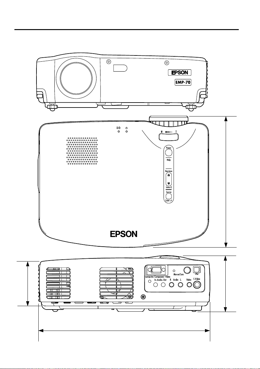
8.6 External Dimensions
The diagram below shows the EMP-70. The EMP-50 has the same external
dimensions.
230 (9.06)
78
99 (3.90)
80 (3.15)
300 (11.81)
Units: mm (inch)
Page 81

8.7 International Warranty System
Your unit is warranted internationally, and you can have it serviced in more than 45
countries outside the country of purchase. Please note that the provisions of the warranty
document pertaining to your product are not those of the international warranty, and that
your warranty applies only when receiving service in a country where the warranty is valid.
The international warranty for your Epson Image Presentation Projector applies
only in the following countries.
<Europe>
• Austria • Belgium • Bulgaria • Croatia • Cyprus
• Czech Republic • Denmark • Finland • France
• Germany • Greece • Hungary • Ireland • Italy
• Luxembourg • Macedonia • Netherlands • Norway • Portugal
• Poland • Ruma nia • S lovakia • Slovenia • Spain
• Sweden • Switzerland • Turkey • United Kingdom • Yugoslavia
<North America / Central America>
• Canada • Costa Rica • Mexico • United States
<South America>
• Argentina • Brazil • Chili • Colombia • Peru
• Venezuela
<Asia / Oceania>
• Australia • Hong Kong • Japan • South Korea • Malaysia
• Singapore • Taiwan • Thailand
The following provisions specify your warranty term and conditions.
1)This warranty is valid on pres entation of a warr anty document or receipt issued in the
country where the product was purchased.
2)This warranty shall be fu lf illed as stipulated by Epson and Epson-des i gnate d serv ice
organizations in the countries listed in this manual.
• The warranty period is 12 months from purchase.
• This warranty extends to the cost of parts and labor as stipulated by the
initial terms of the Epson warranty.
• Loan of a replacement unit will generally not be provided during service.
3)This warranty shall not apply in the following circumstances.
a. Failure of wear items (lamp) or accessories
b. Improper use by the customer, damage due to shipping, or handling not in
accordance with this manual
c. Service or modification by a third party other than Epson or an Epson designated service organization
d. Problems occurring after the use of accessories or wear parts other than
genuine Epson or Epson-quality assured accessories or parts.
Caution
The power cord included is based on the electric power specifications in the country
of purchase. For use in other countries, purchase a genuine Epson power cable
designed for use in the country concerned.
International Warranty Contact List for Epson Image Presentation Projectors
This contact list is current as of December 7, 2000. For the latest contact
information, consult the online home page of the contact in each country, indicated
below. If no information is shown, consult our main home page at www.epson.com.
79
Page 82

EUROPE
AUSTRIA :
EPSON Support Center
Austria
Tech. Help Desk:
00491805 235470
Web Address:
http://www.epson.at
BELGIUM :
EPSON Support Center
BeNeLux
Tech. Help Desk: 032 70222082
Web Address:
http://www.epson.be
BULGARIA :
PROSOFT
6. AI Jendov Str.
BG-1113 Sofia
Tel: 00359.2.730.231
Fax: 00359.2. 9711049
E-mail: Prosoft@internetBG.BG
CROATIA :
Recro d.d.
Trg. Sportova 11
HR-10000 Zagreb
Tel: 00385.1.6350.777
Fax: 00385.1. 6350.716
E-mail: recro@recro.hr
Web Address:
http://www.recro.hr
CYPRUS :
CTC- INFOCOM
6a. lonos Str., Engomi
P. O. Box 1744
2406 Nicosia, Cyprus
Tel: 00357.2.458477
Fax: 00357.2. 668490
CZECH :
EPRINT s.r.o.
Stresovicka 49
CZ-16200 Praha 6
Tel: 00420.2.20180610
Fax: 00420.2. 20180611
E-mail: eprint@mbox.vol.cz
DENMARK :
Tech. Help Desk: 80881127
FINLAND :
Tech. Help Desk: 0800.523010
(note. Some geog raphical
areas excluded)
FRANCE :
EPSON France,
68 bis rue Marjolin, F-92300
Levallois,
Tech. Help Desk:0 1.49.61.33.95
Web Address:
http://www.epson.fr
GERMANY :
EPSON Deutschland
GmbH
Zülpicher Straße 6
40549 Düsseldorf
Tech. Help Desk: 01805 235470
Web Address:
http://www.epson.de
GREECE :
Pouliadis Ass. Corp.
Aristotelous St. 3
GR-19674 Athens
Tel: 0030.1 .9242072
Fax: 0030.1.94410 66
HUNGARY :
R.A. Trade Kft.
Petöfi Sandor u. 64
H-2040 Budaör
Tel: 0036.23.415.317
Fax: 0036.23.417.310
IRELAND :
Tech. Help Desk: 01.6799016
ITALY :
EPSON Italia s.p.a.
Assistenza e Servizio Clienti
Viale F. Lli Casiragi, 427
20099 Sesto
San Giovanni (M I)
Tech. Help Desk: 02.29400341
Web Address:
http://www.epson.it
LUXEMBURG :
EPSON Support Center
BeNeLux
Tech. Help Desk:
0032 70 222082
Web Address:
http://www.epson.be
MACEDONIA :
Rema Kompjuteri d.o.o.
St. Naroden Fro nt 19a lok 16
91000 Skopje/ Macedonia
Tel: 00389.91.118 159
Fax: 00389.91.118159
NETHERLANDS :
EPSON Support Center
BeNeLux
Tech. Help Desk: 043 35 15752
Web Address:
http://www.epson.nl
NORWAY :
Tech. Help Desk: 800.11828
PORTUGAL :
EPSON Portugal, S.A.
Rua do Progresso, 47 1-1
Perafita- Apartado 5132
Tech. Help Desk: 0808 200015
Web Address:
http://www.epson.pt
POLAND :
FOR EVER Sp. z.o.o.
Ul. Frankciska Kawy 44
PL- 01-496 Warszawa
Tel: 0048.22.638.978 2
Fax: 0048.22. 638.9786
E-mail: office@for-ever.com .p l
ROMANIA :
MB Distribution S.R. L.
162, Barbu Vacarescu Blvd.
Sector 2
RO- 71422 Bucharest
Tel: 0040.1.2300314
Fax: 0040.1. 2300313
E-mail: office@mbd-epson.ro
80
Page 83

SLOVAKIA :
Print Trade spol. s.r.o.
Cajkovskeho 8
SK-98401 Lucenec
Tel: 00421.8 63.4331517
Fax: 00421.863 .4325656
E-mail: Prntr d@lc.psg.SK
Web Address:
http://www.printtrade.sk
SLOVENIA :
Repro Ljubljana d.o.o.
Smartinska 106
SLO-1001 Ljubljana
Tel: 00386.6 1 .1853411
Fax: 00386.61.1400126
SPAIN :
EPSON IBERICA, S.A.
Avda. Roma 18-26,
08290 Cerdanyola del Valles,
Barcelona, SPAIN
Centro At. Cliente: 902 404142
E-mail: soporte@epson.es
Web Address:
http://www.epson.es
SWEDEN :
Tech. Help Desk: 08 445 12 58
SWITZERLAND :
EXCOM Service AG
Moosacher Str. 6
CH-8820 Wädenswil
Tel: 01.7822111
Fax: 01.7822349
Web Address:
http://www.excom.ch
UNITED KINGDOM :
EPSON (UK) Ltd.
Campus 100, Maylands Avenue
Hemel Hempstead,
Herts, HP2 7TJ
Tech. Help Desk: 0990 133640
Web Address:
http://www.epson.uk
YUGOSLAVIA :
BS Procesor d.o.o.
Hadzi Nikole Zivkovica 2
11000 Beograd
Tel: 00381.11.639610
Fax: 00381.11.6 39 61 0
NORTH, CENTRAL
AMERICA & CARIBBEANI
ISLANDS
CANADA :
Epson Canada, Ltd.
100 Mural Street, Suite 300
Richmond Hill, Ontario
CANADA L4B IJ3
Tel: 905-709-3839
Web Address:
http://www.epson.com
COSTA RICA :
Epson Costa Rica, S.A.
Embajada Americana,
200 Sur y 300 Oeste
San Jose, Costa Rica
Tel: (50 6) 296-6 222
Web Address:
http://www.epsoncr.com
MEXICO :
Epson Mexico, S.A. de C.V.
AV. Sonora #150
Mexico, 06100, DF
Tel: (52 5) 328-4 008
Web Address:
http://www.epson.com.mx
U. S. A. :
Epson America, Inc.
3840 Kilroy Airport Way
Long Beach, CA 90806
Tel: (562)276-4394
Web Address:
http://www.epson.com
TURKEY :
Romar Pazarlama
Sanayi ve TIC. A.S.
Rihtim Cad. No. 201
Tahir Han
TR-Karaköy-Istanbul
Tel: 0090.212.2520809
Fax: 0090.212.2580804
81
Page 84

SOUTH AMERICA
ARGENTINA :
Epson Argentina S.A.
Avenida Belgrano 964/970
(1192), Buenos Aires
Tel: (54 11) 4346-0300
Web Address:
http://www.epson.com.ar
BRAZIL :
Epson Do Brasil Ltda.
Av. Tucunare, 720
Tambore Barueri,
Sao Paulo, SP 06460-0 2 0
Tel: (55 11) 7295-1757
Web Address:
http://www.epson.com.br
CHILE :
Epson Chile S.A.
La Concepcion 322
Providencia, Santiago
Tel: (562) 236- 2543
Web Address:
http://www.epson.cl
COLOMBIA :
Epson Colombia Ltda.
Diagonal 109, 15-49
Bogota, Colombia
Tel: (57 1) 523-5000
Web Address:
http://www.epson.com.co
PERU :
Epson Peru S.A.
Av. Del Parque Sur #400
San Isidro, Lima, Peru
Tel: (51 1) 224-2336
Web Address:
http://www.epson.com
VENEZUELA :
Epson Venezuela S.A.
Calle 4 con Calle 11-1
La Urbina Sur
Caracas, Venezuela
Tel: (58 2) 241-0433
Web Address:
http://www.epson.com.ve
ASIA & OCEANIA
AUSTRALIA :
EPSON AUSTRALIA PTY
LIMITED
70 Gibbes Street Chatswood
NSW 2067 AUSTRALIA
Tel: 1300 361 054
Web Address:
http://www.epson.com.au
HONGKONG :
EPSON Technical
Support Centre
(Information Centre)
Rooms 4706-4710,
China Resources Building,
26 Harbour Road, Wan Chai,
HONG KONG
Tech. Hot Line: (852) 2585
4399
Fax: (852) 2827 4383
Web Address:
http://www.epson.com.hk
JAPAN :
SEIKO EPSON
CORPORATION
SHIMAUCHI PLANT
VD Customer Support Group:
4897 Shimauchi,
Matsumoto-shi, Nagano-ken,
390-8640 JAPAN
Tel: 0263-48-5438
Fax: 0263-48-5 680
http://www.i-love-epson.co.jp
KOREA :
EPSON KOREA CO., LTD
17F HANSOL Bldg., 736-1,
Yaoksam-dong Kangnam-gu,
Seoul, 135-080, KOREA
Tel: 2-553-3515
Fax: 2-5584271
http://www.epson.co.kr
MALAYSIA :
EPSON TRADING
(MALAYSIA) SDN. BHD.
No. 21 Jalan U 1/19, Seksyen
U1, Hicom-grenmarie Industrial
Park, 40150 Shan Ala m ,
Selangor Darul Ehsan
Tel: 03-5191366
Fax: 03-5191386
SINGAPORE :
EPSON SINGAPORE
PTE. LTD.
401 Commonwealth Drive
#01-01 Haw Par Technocentre
SINGAPORE 149598
Tel: 4722822
Fax: 4726408
TAIWAN :
EPSON Taiwan
Technology & Trading Ltd.
10F, No.287, Nanking East
Road, Section 3, Taipei,
Taiwan,China
Tel: 02-2717-7360 ext. 327
Fax: 02-2713-2155
http://www.epson.com.tw
THAILAND :
EPSON (Thailand) Co.,Ltd.
24th Floor, Empire Tower,
195 South Satho rn Road,
Yannawa, Sathorn, Bangkok
10120, Thailand.
Tel: 6700680 Ext. 309,316,317
Fax: 6700688
http://www.epson.co.th
Epson Technical Center
21st Floor, Payat hai Tower,
128/227 Payath ai Road,
Rachataewee, Bangkok 10400,
Thailand.
Tel: 6120291
Fax: 2165005
http://www.epson-tech.in.th
~
3
82
Page 85

DECLARATION of CONFORMITY
according to ISO/IEC Guide 22 and EN 45014
Manufacturer : SEIKO EPSON CORPORATION
Address : 3-5, Owa 3-chome, Suwa-shi,
Nagano-ken 392-8502 Japan
Representative : EPSON EUROPE B. V.
Address : Entrada 701, 1096 EJ
AMSTERDAM, The Netherlands
Declares that the Product
Kind of Equipment : LCD Projecto r
Model : ELP-70 / EMP-70
ELP-50 / EMP-50
Conforms to the following Directives and Norm(s)
Directive 89/336/EEC
: EN 55022
: EN 55024
Directive 73/23/EEC
: EN 60950
Page 86

DECLARATION of CONFORMITY
According to 47CFR, Part 2 and 15 for
Class B Personal Computers and Peripherals; and/or
CPU Boards and Power Supplies used with Class B
Personal Computers
We : EPSON AMERICA, INC.
Located at : MS: 3-13
3840 Kilroy Airport Way
Long Beach, CA 90806-2469
Telephone: (562) 290- 5254
Declare under sole responsibility tha t the product identified herein,
complies with 47CFR Part 2 and 15 of the FCC rul es as a Class B digit al
device. Each product marketed, is ide n tical to the representative unit
tested and found to be compliant with the standards. Records
maintained continue to reflect the equipment being prod uced can be
expected to be within the var iation acc epted, due to quantit y production
and testing on a statistic al basis as requir ed by 47CFR 2.909. Operation
is subject to the following two conditions : (1) this device may not cause
harmful interference, and (2) this device must accept any interference
received, including interference that may cause undesired operation.
Trade Name : EPSON
Type of Product : LCD Projector
Model : EMP-70/50 / ELP-70/50
Page 87

FCC Compliance Statement
For United States Users
This equipment has been te sted and found to comply wit h the limit s for a
Class B digital device, pursuant to Part 15 of the FCC Rules. These
limits are designed to provide reasonable protection against harmful
interference in a residential installation. This equipment generates,
uses, and can radiate radio frequency energy and, if not installed and
used in accordance with the instructions, may cause harmful
interference to radio or television reception. However, there is no
guarantee that interference wil l not occur in a particular installation. If
this equipment does cause interference to radio and television
reception, which can be determined by turning the equipment of f and
on, the user is encouraged to try to correct the interference by one or
more of the following measures.
• Reorient or relocate the receiving antenna.
• ncrease the separation between the equipment and receiver.
• Connect the equipment into an outlet on a cir cuit diffe rent f rom that t o
which the receiver is connected.
• Consult the dealer or an experienced radio/TV technician for help.
WARNING
The connection of a non-shielded equipment interface cable to this
equipment will invalidate the FCC Certification or Declaration of this
device and may cause interference levels which exceed the limits
established by the FCC for this equipment. It is the responsibility of the
user to obtain and use a shielded equipment interface cable with this
device. If this equipment has more than one interface connector, do not
leave cables connected to unused interface s. Changes or modificati ons
not expressly approved by the manufacturer could void the user ’s
authority to operate the equipment.
For Canadian Users
This digital apparatus does no t exceed t he Cl ass B li mits fo r radi o noise
emissions from digital apparatus as set out in the radio interference
regulations of the Canadian Department of Communic ations.
Le présent appareil numérique n’émet pas de bruits radioélectriques
dépassant les limites applicables au x appareils numériques de Classe B
prescrites dans le règl ement sur le brouillage radioélectrique édicté par
le Ministère des Communications du Canada.
Page 88

 Loading...