

Page 1
Register your instrument!
www.eppendorf.com/myeppendorf
Top Buret
Operating manual
™
Page 2

Copyright
©
2013 Eppendorf AG, Hamburg. No part of this publication may be
reproduced without the prior permission of the copyright owner.
Eppendorf and the Eppendorf logo are a registered trademark of Eppendorf AG.
®
Trademarks are not marked in all cases with ™ or
in this manual.
4965 900.018-03/032013
Page 3

Table of contents
Top Bu ret
English (EN)
Operating manual Top Buret™seeon p.Fig.Tab.p.
English (EN)Operating manual
Table of contents
1 Operating instructions . . . . . . . . . . . . . . . . . . . . . . . . . . . . . . . . . . . . . . . . . 5
1.1 Using this manual . . . . . . . . . . . . . . . . . . . . . . . . . . . . . . . . . . . . . . . . 5
1.2 Danger symbols and danger levels . . . . . . . . . . . . . . . . . . . . . . . . . . . 5
1.2.1 Danger symbols . . . . . . . . . . . . . . . . . . . . . . . . . . . . . . . . . . 5
1.2.2 Danger levels . . . . . . . . . . . . . . . . . . . . . . . . . . . . . . . . . . . . 5
1.3 Symbols used . . . . . . . . . . . . . . . . . . . . . . . . . . . . . . . . . . . . . . . . . . . 6
1.4 Abbreviations used . . . . . . . . . . . . . . . . . . . . . . . . . . . . . . . . . . . . . . .6
2 Product description . . . . . . . . . . . . . . . . . . . . . . . . . . . . . . . . . . . . . . . . . . . 7
2.1 Main illustration . . . . . . . . . . . . . . . . . . . . . . . . . . . . . . . . . . . . . . . . .7
2.2 Delivery package. . . . . . . . . . . . . . . . . . . . . . . . . . . . . . . . . . . . . . . . . 9
2.3 Features . . . . . . . . . . . . . . . . . . . . . . . . . . . . . . . . . . . . . . . . . . . . . . .9
2.4 Materials . . . . . . . . . . . . . . . . . . . . . . . . . . . . . . . . . . . . . . . . . . . . . . 10
3 Safety . . . . . . . . . . . . . . . . . . . . . . . . . . . . . . . . . . . . . . . . . . . . . . . . . . . . .11
3.1 Intended use . . . . . . . . . . . . . . . . . . . . . . . . . . . . . . . . . . . . . . . . . . .11
3.2 User profile . . . . . . . . . . . . . . . . . . . . . . . . . . . . . . . . . . . . . . . . . . . .12
3.3 Warnings for intended use . . . . . . . . . . . . . . . . . . . . . . . . . . . . . . . .13
3.4 Information on product liability . . . . . . . . . . . . . . . . . . . . . . . . . . . . 14
™
3
4 Installation . . . . . . . . . . . . . . . . . . . . . . . . . . . . . . . . . . . . . . . . . . . . . . . . . 15
4.1 Mounting the device . . . . . . . . . . . . . . . . . . . . . . . . . . . . . . . . . . . . .15
4.2 Inserting the batteries. . . . . . . . . . . . . . . . . . . . . . . . . . . . . . . . . . . . 17
4.3 Mounting the telescopic aspirating tube . . . . . . . . . . . . . . . . . . . . . 18
4.3.1 Extending the telescopic aspirating tube . . . . . . . . . . . . . . 18
4.3.2 Shortening the telescopic aspirating tube . . . . . . . . . . . . . 18
4.3.3 Mounting the telescopic aspirating tube . . . . . . . . . . . . . .19
4.4 Mounting the Top Buret on the bottle . . . . . . . . . . . . . . . . . . . . . . . 19
4.5 Connecting the drying tube . . . . . . . . . . . . . . . . . . . . . . . . . . . . . . .21
5 Operation . . . . . . . . . . . . . . . . . . . . . . . . . . . . . . . . . . . . . . . . . . . . . . . . . . 22
5.1 Dispensing settings. . . . . . . . . . . . . . . . . . . . . . . . . . . . . . . . . . . . . . 22
5.2 Deairing the Top Buret . . . . . . . . . . . . . . . . . . . . . . . . . . . . . . . . . . .23
5.3 Titrating liquid . . . . . . . . . . . . . . . . . . . . . . . . . . . . . . . . . . . . . . . . .24
5.4 Changing the supply bottles during titration . . . . . . . . . . . . . . . . . .25
5.5 Removing the bottle . . . . . . . . . . . . . . . . . . . . . . . . . . . . . . . . . . . . .26
5.6 Emptying the device . . . . . . . . . . . . . . . . . . . . . . . . . . . . . . . . . . . . .26
Page 4

Table of contents
4
Top Buret
English (EN)
™
6 Calibration and adjustment . . . . . . . . . . . . . . . . . . . . . . . . . . . . . . . . . . . .27
6.1 Calibrating the Top Buret . . . . . . . . . . . . . . . . . . . . . . . . . . . . . . . . . 27
6.1.1 Measuring the testing volume . . . . . . . . . . . . . . . . . . . . . . 27
6.1.2 Calculating the error . . . . . . . . . . . . . . . . . . . . . . . . . . . . . . 27
6.1.3 Evaluating the calibration . . . . . . . . . . . . . . . . . . . . . . . . . .28
6.2 Adjusting the Top Buret . . . . . . . . . . . . . . . . . . . . . . . . . . . . . . . . . .28
6.2.1 Adjustment to distilled water . . . . . . . . . . . . . . . . . . . . . . .29
6.2.2 Adjustment to a liquid with a different density. . . . . . . . . . 29
6.3 Resetting the Top Buret to the factory settings . . . . . . . . . . . . . . . .30
7 Troubleshooting . . . . . . . . . . . . . . . . . . . . . . . . . . . . . . . . . . . . . . . . . . . . . 31
7.1 Troubleshooting . . . . . . . . . . . . . . . . . . . . . . . . . . . . . . . . . . . . . . . .31
8 Maintenance . . . . . . . . . . . . . . . . . . . . . . . . . . . . . . . . . . . . . . . . . . . . . . . .32
8.1 Cleaning the Top Buret . . . . . . . . . . . . . . . . . . . . . . . . . . . . . . . . . . .32
8.1.1 Standard cleaning . . . . . . . . . . . . . . . . . . . . . . . . . . . . . . . .33
8.1.2 Intensive cleaning . . . . . . . . . . . . . . . . . . . . . . . . . . . . . . . . 33
8.2 Disassembling the Top Buret . . . . . . . . . . . . . . . . . . . . . . . . . . . . . . 34
8.3 Replacing the batteries . . . . . . . . . . . . . . . . . . . . . . . . . . . . . . . . . . . 35
9 Technical data. . . . . . . . . . . . . . . . . . . . . . . . . . . . . . . . . . . . . . . . . . . . . . .36
9.1 Ambient conditions. . . . . . . . . . . . . . . . . . . . . . . . . . . . . . . . . . . . . .36
9.2 Errors . . . . . . . . . . . . . . . . . . . . . . . . . . . . . . . . . . . . . . . . . . . . . . . .36
9.3 Parameters for titratable media . . . . . . . . . . . . . . . . . . . . . . . . . . . . 36
9.4 Conditions for calibration . . . . . . . . . . . . . . . . . . . . . . . . . . . . . . . . .36
10 Ordering Information. . . . . . . . . . . . . . . . . . . . . . . . . . . . . . . . . . . . . . . . . 37
10.1 Devices . . . . . . . . . . . . . . . . . . . . . . . . . . . . . . . . . . . . . . . . . . . . . . .37
10.2 Spare parts . . . . . . . . . . . . . . . . . . . . . . . . . . . . . . . . . . . . . . . . . . . .37
10.3 Threaded adapter . . . . . . . . . . . . . . . . . . . . . . . . . . . . . . . . . . . . . . . 37
11 Transport, storage and disposal . . . . . . . . . . . . . . . . . . . . . . . . . . . . . . . . 38
11.1 Transport. . . . . . . . . . . . . . . . . . . . . . . . . . . . . . . . . . . . . . . . . . . . . .38
11.2 Storage . . . . . . . . . . . . . . . . . . . . . . . . . . . . . . . . . . . . . . . . . . . . . . .38
11.3 Disposal. . . . . . . . . . . . . . . . . . . . . . . . . . . . . . . . . . . . . . . . . . . . . . . 39
12 Measurement report . . . . . . . . . . . . . . . . . . . . . . . . . . . . . . . . . . . . . . . . . 40
Page 5
Operating instructions
Top Bu ret
English (EN)
1 Operating instructions
1.1 Using this manual
Read this operating manual completely before using the device for the first
time. Please also note the operating instructions for the accessories, if
applicable.
This operating manual is part of the product. Thus, it must always be easily
accessible.
Enclose this operating manual when transferring the device to third parties.
1.2 Danger symbols and danger levels
The safety instructions in this manual appear with the following danger symbols
and danger levels:
1.2.1 Danger symbols
Biohazard Explosion
Tox ic subst ances Hazard point
™
5
Material damage
1.2.2 Danger levels
DANGER Will lead to severe injuries or death.
WARN ING May lead to severe injuries or death.
CAUTION May lead to light to moderate injuries.
NOTICE May lead to material damage.
Page 6
Operating instructions
6
Top Buret
English (EN)
™
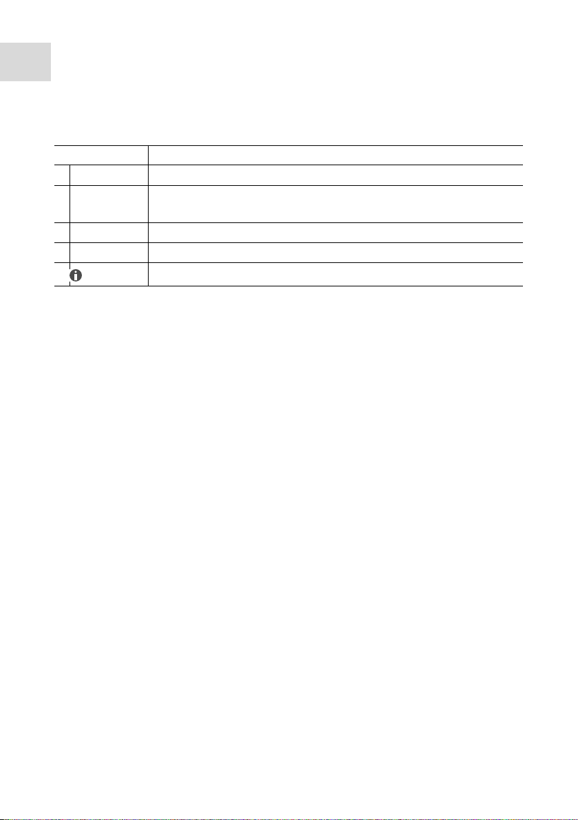
1.3 Symbols used
Symbol Meaning
Handling
1.
Actions in the specified order
2.
• List
Text Name of fields in the software
Useful information
1.4 Abbreviations used
ETFE
Ethylene-tetrafluoroethylene copolymer
FEP
Tetrafluoroethylene-perfluoropropylene copolymer
FKM
Fluororubber
PFA
Perfluoroalkoxy copolymer
PP
Polypropylene
PTFE
Polytetrafluorethylene
PVDF
Polyvinylidene fluoride
Page 7
2 Product description
Start
Pause
ml
Calibrate
Reset
Top Buret M
1
5
4
3
2
8
7
6
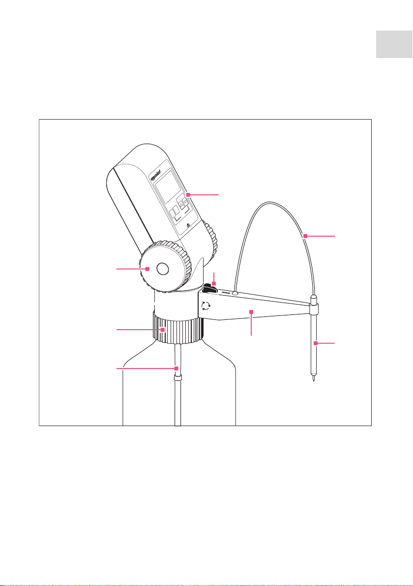
2.1 Main illustration
Abb. 2-1: Top Buret M/H
Product description
Top Bu ret
English (EN)
™
7
Fig. 2-1: Top Buret M/H
1 Control panel
2 Discharge tube
3 Canula holder
4 Canula arm
5 Discharge valve toggle
6 Telescopic aspirating tube
7 Bottle thread
8 Dispensing wheels
Page 8
Product description
Top Buret H
1
2
3
7
8
9
6
5
4
8
Top Buret
English (EN)
Abb. 2-2: Operating controls
™
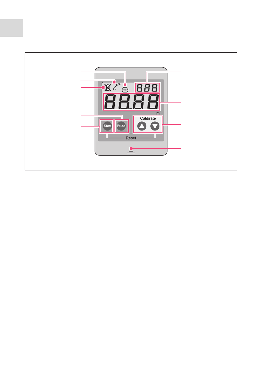
Fig. 2-2: Operating controls
1Calibration mode
2Volume display
3Arrow keys
4 Opening symbol
5Start key
6Pause key
7 Battery flat symbol
8 Titration mode symbol
9 Pause symbol
Page 9

2.2 Delivery package
Number Description
1 Eppendorf Top Buret M 25 mL
or Eppendorf Top Buret H 50 mL
1 Canula arm
1 Discharge tube with knurled nut
1 Canula holder
1 Telescopic aspirating tube
1 Bottle thread adapter
From GL 45 to S 40 (buttress thread), PP
From GL 45 to GL 38, PP
From GL 38 to GL 32, PP
1 Battery
LR03/AAA, 1.5 V, set of 2
1 Eppendorf Top Buret M/H operating manual
2.3 Features
Product description
Top Bu ret
English (EN)
™
9
The Top Buret is a bottle-top buret which features a continuous, pulse-free
dispensing technique. The Top Buret can dispense volumes between 10 μL and
999.9 mL at a maximum concentration of 1 mol/L.
When the dispensing wheels are fully rotated, the following volumes are
dispensed:
• Top Buret M: 2.5 mL
• Top Buret H: 5.0 mL
The Top Buret has two dispensing settings. The dispensing settings are set with
the toggle on the canula arm.
• Titration
Titrate liquid from the bottle to a destination vessel.
• Deairing
Rinse liquid through the discharge valve into the bottle, e.g., to remove air
bubbles.
Page 10

Product description
10
Top Buret
English (EN)
™
2.4 Materials
NOTICE! Aggressive substances may damage the Top Buret and
accessories.
Check the chemical resistance before using organic solvents or
aggressive chemicals.
Follow the cleaning instructions.
The assembly parts of the Top Buret consist of the following materials:
Assembly parts that come into
contact with liquid
• Borosilicate glass 3.3 (Boro 3.3)
• Ethylene-tetrafluoroethylene
copolymer (ETFE)
• Perfluoroalkoxy copolymer (PFA)
• Tetrafluoroethylene-
perfluoropropylene copolymer (FEP)
• Platinum iridium (Pt-Ir)
• Polytetraflourethylene (PTFE)
Assembly parts that do not come into
contact with liquid
• Stainless steel
• Fluororubber (FKM)
•Polyester
•Polypropylene (PP)
• Polyvinylidene fluoride (PVDF)
• Polyamide (PA)
• Polyoxymethylene (POM)
• Polyphenylene sulfide (PPS)
Page 11

Safety
Top Bu ret
English (EN)
3 Safety
3.1 Intended use
The Top Buret is a laboratory device for dispensing aqueous solutions in a
volume range between 10 μL and 999.9 mL. Applications in or on the human
body (in vivo applications) are not permitted.
The device must not be exposed to an aggressive atmosphere, e.g., HCI vapors.
The device must not be autoclaved.
The device is intended for dispensing liquids with the following properties:
• Maximum concentration: 1 mol/L
• Maximum density: 2.2 g/cm
• Maximum vapor pressure: 50 kPa
The following reagents must not be titrated with the device:
• Liquids which attack PFA, ETFE, PTFE, Boro 3.3 or FEP
• Solutions containing hydrofluoric acid, since they attack borosilicate glass
• Unstable substances because they react catalytically with platiniridium, e.g.,
hydrogen peroxide
• Solutions prone to crystallization
• Suspensions containing solid particles
• Fuming acids or highly concentrated alkaline solutions
• Solutions which decompose and form solid particles, e.g., Biuret reagent
• Carbon disulfide, as it is highly flammable
3
™
11
The Top Buret is suitable for dispensing the following titration solutions up
to a concentration of 1 mol/L:
• Ammonium iron(II) sulfate solution
• Ammonium thiocyanate solution
• Barium chloride solution
• Bromid bromate solution
• Cerium(IV) sulfate solution
• EDTA solution
• Iron(II) sulfate solution
• Acetic acid
Page 12

Safety
12
Top Buret
English (EN)
™
• Iodine solution
• Caustic potash solution
• Potassium bromate solution
• Potassium bromide bromate solution
• Potassium dichromate solution
• Potassium iodate solution
• Potassium permanganate solution
• Potassium thiocyanate solution
• Sodium arsenite solution
• Sodium carbonate solution
• Sodium chloride solution
• Sodium nitrite solution
• Sodium thiosulfate solution
• Caustic soda
•Oxalic acid
•Perchloric acid
• Nitric acid
•Hydrochloric acid
•Sulfuric acid
•Silver nitrate solution
• Tetra-n-butylammonium hydroxide solution
• Zinc sulfate solution
Refer to the information provided by the reagent manufacturers. If you have any
questions, contact Eppendorf Service.
3.2 User profile
The device and accessories may only be operated by trained and skilled
personnel.
Before using the device, read the operating manual carefully and familiarize
yourself with the device's mode of operation.
Page 13
3.3 Warnings for intended use
DANGER! Risk of explosion.
Do not operate the device in areas where work is completed with
explosive substances.
Do not use this device to process any explosive or highly reactive
substances.
Do not use this device for processing any substances which could
generate an explosive atmosphere.
WARNING! Damages to health due to infectious liquids and
pathogenic germs.
When handling infectious liquids and pathogenic germs, observe the
national regulations, the biological security level of your laboratory,
the material safety data sheets, and the manufacturer's application
notes.
Wear personal protective equipment.
Consult the "Laboratory Biosafety Manual" (Source: World Health
Organization, Laboratory Biosafety Manual, as amended) for
comprehensive regulations on the handling of risk group II germs or
biological materials).
Safety
Top Bu ret
English (EN)
™
13
WARNING! Damage to health due to toxic, radioactive or aggressive
chemicals.
Wear personal protective equipment.
Observe the national regulations for handling these substances.
Observe the material safety data sheets and manufacturer's
application notes.
Page 14

Safety
14
Top Buret
English (EN)
™
CAUTION! Contamination from biological or chemical substances.
Only initiate dispensing if it is safe to do so.
Do not place people in danger during dispensing.
Turn the dispensing wheels slowly and evenly to prevent spraying.
Never point the opening of the discharge tube toward people.
CAUTION! Poor safety due to incorrect accessories and spare parts.
The use of accessories and spare parts other than those recommended
by Eppendorf may impair the safety, functioning and precision of the
device. Eppendorf cannot be held liable or accept any liability for
damage resulting from the use of incorrect or non-recommended
accessories and spare parts, or from the improper use of such
equipment.
Only use accessories and original spare parts recommended by
Eppendorf.
NOTICE! Damage to the device due to autoclaving.
Do not autoclave the device.
3.4 Information on product liability
In the following cases, the designated protection of the device may be
compromised. Liability for any resulting property damage or personal injury is
then transferred to the operator:
• The device is not used in accordance with the operating manual.
• The device is used outside of its intended use.
• The device is used with accessories or consumables which are not
recommended by Eppendorf.
• The device is maintained or repaired by people not authorized by Eppendorf.
• The user makes unauthorized changes to the device.
Page 15

4 Installation
Top Buret H
2
1
14
13
10
11
12
8
9
7
5
6
3
4
4.1 Mounting the device
Abb. 4-1: Top Buret
Installation
Top Bu ret
English (EN)
™
15
Fig. 4-1: Top Buret
1 Control panel
2 Discharge tube
3 Canula holder
4 Canula arm
5 Knurled nut
6 Discharge valve toggle
7Discharge valve
8 Recirculation tube
9 Telescopic aspirating tube
10 connection opening
11 Bottle thread
12 Valve head
13 Air vent cover
14 Dispensing wheels
Page 16

Installation
16
Top Buret
English (EN)
™
To assemble the device, proceed as follows:
1. Rotate the discharge valve toggle to
the deairing position. Remove the
toggle upwards.
2. The canula holder has gripping nubs
on the inside for the canula at one
end. Insert the canula holder into
the canula arm mount ensuring that
the gripping nubs are below.
3. Guide the free end of the discharge
tube through the hole in the canula
arm from below.
4. Insert the free end of the discharge
tube into the canula holder from
above until it protrudes slightly at
the bottom.
5. Screw the discharge tube with the
knurled nut onto the discharge
valve.
Page 17

Installation
Top Bu ret
English (EN)
6. Slide the canula arm over the
discharge valve from above up to the
stop.
7. Attach the discharge valve toggle.
™
17
4.2 Inserting the batteries
NOTICE! Damage to the battery compartment due to inserting the
batteries incorrectly.
Observe the correct polarity of the batteries.
Do not use force.
The display automatically switches on when the batteries are inserted. If
the device is not used, the display will switch off after about 5 minutes.
Page 18

Installation
18
Top Buret
™
English (EN)
Proceed as follows:
Abb. 4-2: Removing the control panel
1. Press and hold the opening symbol.
2. Slide the control panel upwards and
remove it.
ml
Calibrate
Pause
Start
Reset
Top Buret M
3. Remove the battery compartment lid
at the back of the control panel.
4. Insert the batteries.
5. Replace the battery compartment
lid.
6. Attach the control panel and slide it
downwards until it engages.
Fig. 4-2: Removing the control panel
To remove the batteries, proceed in the reverse order.
4.3 Mounting the telescopic aspirating tube
The Top Buret conveys the liquid through the telescopic aspirating tube from the
supply bottle. Adjust the length of the telescopic aspirating tube to the bottle
height to empty the bottle completely.
4.3.1 Extending the telescopic aspirating tube
Prerequisites
• The device has been mounted (see p. 15)
• The bottle is larger than the collapsed telescopic aspirating tube
Proceed as follows:
Push the inner tube out of the outer tube until the tube length corresponds to
the length of the bottle.
4.3.2 Shortening the telescopic aspirating tube
Prerequisites
• The device has been mounted (see p. 15)
• The bottle is smaller than the collapsed telescopic aspirating tube
Page 19

Proceed as follows:
1. Push the inner tube completely out of the outer tube.
2. Shorten both tubes to the required length using a pair of scissors.
3. Insert the inner tube into the outer tube.
4.3.3 Mounting the telescopic aspirating tube
Installation
Top Bu ret
English (EN)
™
19
Abb. 4-3: Sliding the telescopic aspirating tube onto the connection opening
1. Slide the inner tube onto the
connection opening up to the stop.
2. Pull out the outer tube so that it
stops short of the bottom of the
bottle.
3. Cut the lower end of the outer tube
off at an angle.
Fig. 4-3: Sliding the telescopic
aspirating tube onto the
connection opening
4.4 Mounting the Top Buret on the bottle
CAUTION! Personal injury due to incorrect transportation of buret.
If the mounted buret is not transported properly, reagents may be
released. Contact with reagents may be harmful to eyes or skin.
To transport the mounted buret, grasp the buret with one hand and
the bottle with the other hand.
Do not hold the buret by the housing.
Page 20

Installation
20
Top Buret
English (EN)
™
CAUTION! Personal injury due to contact with reagents.
Contact with reagents may be harmful to eyes or skin.
Wear personal protective equipment.
Make sure that no reagents are leaking from the buret.
The Top Buret can be directly screwed onto bottles with a GL 45 thread. The
adapters from the delivery package (see p. 9) and the accessories available for
ordering (see p. 37) allow the use on bottles with other threads.
Prerequisites
• The device has been mounted (see p. 15)
• The telescopic aspirating tube has been attached (see p. 18)
• The length of the telescopic aspirating tube has been adjusted to the length of
the bottle.
Proceed as follows:
Abb. 4-4: Screwing the Top Buret onto the bottle
Fig. 4-4: Screwing the Top Buret
onto the bottle
1. If the bottle has a different thread to
the Top Buret, use the appropriate
adapter.
2. Rotate the discharge valve toggle to
deairing.
3. Attach the Top Buret onto the bottle
from above.
4. If necessary, correct the length of
the telescopic aspirating tube.
5. Screw the Top Buret onto the bottle.
Page 21

Installation
Top Bu ret
English (EN)
4.5 Connecting the drying tube
For the titration of hygroscopic liquids you need a drying tube. The drying tube
must be filled with suitable liquid absorbers.
The drying tube is not included in the delivery package. You can order the
drying tube as an accessory.
Suitable liquid absorbers:
• Silica gel with a particle size of 1 mm – 3 mm
•CaCO
• NaOH pills (5 mm ø, for the absorption of CO2)
Prerequisites
• The batteries have been inserted (see p. 17)
• The device has been mounted (see p. 15)
• The telescopic aspirating tube has been mounted (see p. 18)
• The device has been screwed onto a bottle (see p. 19)
Proceed as follows:
2
™
21
Abb. 4-5: Removing the air vent cover
Fig. 4-5: Removing the air vent cover
1. Remove the air vent cover.
2. Insert the drying tube into the
opening.
3. Fill the drying tube with moisture
absorber.
Page 22

Operation
22
Top Buret
English (EN)
™
5 Operation
5.1 Dispensing settings
The Top Buret has two dispensing settings. The dispensing settings are set with
the toggle on the canula arm.
1. Titration
Symbol for the toggle setting:
Titrate liquid from the bottle to a
destination vessel.
2. Deairing
Symbol for the toggle setting:
Rinse liquid through the discharge
valve back into the bottle, e.g., to
remove air bubbles.
Page 23

Operation
Top Bu ret
English (EN)
5.2 Deairing the Top Buret
CAUTION! Personal injury due to contact with reagents.
Contact with reagents may be harmful to eyes or skin.
Wear personal protective equipment.
Do not point the discharge tube at people.
Air bubbles in the supply lines and in the feeding mechanics will distort the
measuring results.
Deair the Top Buret in the following situations:
• Prior to initial operation
• After intensive cleaning
• After changing the bottle
• After a long period of inactivity
Proceed as follows:
Prerequisites
• The device has been completely mounted.
™
23
Abb. 5-1: Deairing the int erior system
Fig. 5-1: Deairing the interior system
1. Rotate the discharge valve toggle to
deairing.
2. Remove the control panel.
3. Rotate the dispensing wheels slowly
and evenly forward until there is no
more air left in the system.
Page 24

Operation
24
Top Buret
English (EN)
™
Abb. 5-2: Deairing the discharge tube
Fig. 5-2: Deairing the discharge tube
5.3 Titrating liquid
If you rotate the dispensing wheels backwards, they do not engage. No
dispensing of liquid is performed and no volume is counted.
If the Top Buret is not used, the display will switch off after 5 minutes.
The titrated volume is stored until the next titration.
Proceed as follows:
Abb. 5-3: Titration by rotating the dispensing wheel
Fig. 5-3: Titration by rotating the
dispensing wheel
4. Rotate the discharge valve toggle to
titration.
5. Place a collection vessel below the
canula.
6. Rotate the dispensing wheels
forward until liquid emerges from
the opening of the discharge tube.
7. Attach the control panel.
8. Wipe any chemical residues from
the discharge tube.
1. To switch on the display, press the
Start key.
The display shows either 0.00 or the
volume of the last titration.
2. Press the Start key to set the volume
display to 0.00.
3. Pull out the canula arm to the
desired length.
4. Hold a collection vessel below the
discharge tube.
5. Rotate the discharge valve toggle to
titration.
Page 25

Operation
Top Bu ret
English (EN)
6. Press the Start key to set the volume display to 0.00.
7. Pull out the canula arm to the desired length.
8. Hold a collection vessel below the discharge tube.
9. Rotate the discharge valve toggle to titration.
10.Rotate the dispensing wheels forward to dispense liquid.
11.To end titration, rotate the discharge valve toggle to deairing.
12.To avoid the dispensing of liquid from the discharge tube, set the valve toggle
to recirculation.
5.4 Changing the supply bottles during titration
You can change the supply bottles during a titration sequence without changing
the displayed volume.
Proceed as follows:
1. Press the Pause key.
On the display, the Stop symbol appears. The titrated value is stored.
2. Remove the bottle (see p. 26).
3. Mount the new bottle (see p. 19).
4. Deair the device (see p. 23).
5. Press the Pause key again.
The display is enabled. The display shows the stored value and the titration
symbol .
6. Continue titration.
™
25
Page 26

Operation
26
Top Buret
English (EN)
™
5.5 Removing the bottle
Abb. 5-4: Emptying the telescopic aspirating tube
Fig. 5-4: Emptying the telescopic
aspirating tube
5.6 Emptying the device
1. Rotate the discharge valve toggle to
deairing.
2. Place the Top Buret with bottle into
a suitable collecting vessel.
3. Unscrew the device from the bottle
in a counterclockwise direction.
4. Lift the Top Buret until the
telescopic aspirating tube is no
longer immersed in the liquid.
5. Gently tap the telescopic aspirating
tube against the inside of the bottle.
The residual liquid from the
telescopic aspirating tube runs into
the bottle.
Before changing the liquid and before cleaning, the Top Buret must be emptied.
Proceed as follows:
Prerequisites
• The bottle has been unscrewed (see p. 26)
1. Mount the Top Buret onto an empty bottle.
2. Place a collection vessel below the canula.
3. Rotate the discharge valve toggle to titration.
4. Rotate the dispensing wheels forward until no more liquid runs out of the
discharge tube.
5. Rotate the discharge valve toggle to deairing.
6. Rotate the dispensing wheels forward until no more liquid runs out of the
recirculation tube.
To remove the reagents completely, clean the device.
Page 27

Calibration and adjustment
V = 1/n Vi
∑
n
i = 1
Top Bu ret
English (EN)
6 Calibration and adjustment
6.1 Calibrating the Top Buret
The Top Buret has been calibrated with distilled or deionized water. You can
carry out a gravimetric test of the Top Buret error. The procedure is described in
detail in DIN EN ISO 8655.6.
You need the following auxiliary equipment:
• Distilled water
• Calibrated analytical balance
• Beaker
6.1.1 Measuring the testing volume
Prerequisites
• The device and auxiliary equipment must have the same temperature (20 °C –
25 °C, ±0.5 °C).
Proceed as follows:
1. Set up the calibrated analytical balance at a vibration and draft-free location.
2. Place a beaker on the balance.
3. With the Top Buret M, titrate 25 mL of distilled water into the beaker and
record the weight.
4. Repeat step 3 10 times.
5. With the Top Buret H, titrate 50 mL of distilled water into the beaker and
record the weight.
6. Repeat step 5 10 times.
™
27
6.1.2 Calculating the error
1. Calculate the volume of the water.
2. Calculate the average value of the volumes.
Density of water (ρ) at 16 °C – 21 °C = 0.998 g/mL
Density of water (ρ) at 22 °C – 25 °C = 0.997 g/mL
V =
m
ρ
Page 28

Calibration and adjustment
V
V
(Vi – V)
∑
n
i = 1
n – 1
sr =
V
100 × s
r
CV =
28
Top Buret
English (EN)
™
3. Calculate the inaccuracy (e
(Vs).
) using the nominal volume
s
V – V
es = × 100 %
s
V
s
• = actual volume (average value of the weighings)
= nominal volume (Top Buret M = 25 mL, Top Buret H
•V
s
= 50 mL)
4. Calculate the standard deviation (s
).
r
•sr = standard deviation
• n = number of dispensing steps
= measured value (weight of the sample)
•V
i
• = actual volume (average value of the weighings)
5. Calculate the imprecision (CV).
6.1.3 Evaluating the calibration
1. Compare the results for inaccuracy and imprecision with table (see p. 36).
2. If the errors are within the tolerance range specified in the table, no
adjustment is necessary.
3. If the errors are outside the tolerance range, adjust the device or contact a
service technician.
6.2 Adjusting the Top Buret
The Top Buret has been calibrated and adjusted before delivery. Adjust the Top
Buret in the following situations:
• The calibration error with distilled water is outside the tolerance range
• The density of the titrated liquid differs from the density of distilled water
Calibration is only possible with a testing volume between 10 mL – 90 mL.
Page 29

Calibration and adjustment
Top Bu ret
English (EN)
™
29
If the testing volume is < 10 mL,
the display shows:
If the testing volume is > 90 mL, the display
shows:
To display the set adjustment value, either press the or arrow key
in titration mode. After you release the key, the display automatically
returns to the last volume display.
6.2.1 Adjustment to distilled water
Proceed as follows:
1. Carry out the measurement of the testing volumes and calculate the average
value of the volumes (see Calibrating the Top Buret on p. 27).
2. Use the average value of the volumes that you have obtained from the
calibration.
3. Press the Pause key.
The volume is saved.
4. Press and hold the and arrow keys at the same time for 3 seconds.
The display shows CAL at the top right
5. Set the calculated average value of the volumes using the and arrow
keys.
6. Press the Start key.
• The set value is accepted
• The display is reset to zero
• The adjustment is ended
• The display shows C at the top right. The display indicates that the factory
settings have been changed.
6.2.2 Adjustment to a liquid with a different density
1. Set up the calibrated analytical balance at a vibration and draft-free location.
2. Place a beaker on the balance.
Page 30

Calibration and adjustment
V =
ρ
m
V = 1/n Vi
∑
n
i = 1
30
Top Buret
English (EN)
™
3. With the Top Buret M, titrate 25 mL of the test liquid into the beaker and
record the weight.
4. Repeat step 3 10 times.
5. With the Top Buret H, titrate 50 mL of the test liquid into the beaker and
record the weight.
6. Repeat step 5 10 times.
7. Calculate the volume of the standard solution.
8. Calculate the average value of the volumes.
9. Press the Pause key.
The volume is saved.
10.Press and hold the and arrow keys at the same time for 3 seconds.
The display shows CAL at the top right
11.Set the calculated average value of the volumes using the and arrow
keys.
12.Press the Start key.
• The set value is accepted
• The display is reset to zero
• The adjustment is ended
• The display shows C at the top right. The display indicates that the factory
settings have been changed.
6.3 Resetting the Top Buret to the factory settings
The reset function is used to restore the factory settings. If you have adjusted the
device, the display will show a C. When you restore the factory settings again,
the C will disappear.
1. Press the Start key to switch on the Top Buret.
2. Press and hold the Start and keys at the same time for 3 seconds to activate
•The display C disappears.
• The factory settings have been restored.
the reset function.
Page 31

7 Troubleshooting
7.1 Troubleshooting
Symptom/message Cause Remedy
• Air is aspirated.
•The titrated liquid
contains air bubbles.
Liquid is not aspirated. • The connection
The titration volume is
too small.
The display shows the
symbol.
• The device was not
sufficiently deaired.
•The telescopic
aspirating tube has
not been mounted
completely.
•The telescopic
aspirating tube is
damaged.
•The telescopic
aspirating tube does
not immerse into the
liquid.
•The connection
opening is damaged.
opening is clogged.
•The telescopic
aspirating tube has
not been mounted
completely.
•The telescopic
aspirating tube is
damaged.
• The device is
incorrectly adjusted.
•The connection
opening is damaged.
• The batteries are flat.
Deair the device
(see p. 23).
Slide the telescopic
aspirating tube firmly onto
the connection opening
(see p. 18).
Shorten the telescopic
aspirating tube or replace
it.(see p. 18).
Lengthen the telescopic
aspirating tube until it is
immersed in the liquid
(see p. 18).
Send in the device for repair.
Clean the device
(see p. 32).
Slide the telescopic
aspirating tube firmly onto
the connection opening (see
p. 18).
Shorten the telescopic
aspirating tube or replace it
(see p. 18).
Set the device to the factory
adjustment (see p. 30).
Send in the device for repair.
Replace the batteries.
Troubleshooting
Top Bu ret
English (EN)
™
31
Page 32

Maintenance
32
Top Buret
English (EN)
™
8 Maintenance
8.1 Cleaning the Top Buret
CAUTION! Personal injury due to contact with reagents during
cleaning.
The feeding mechanics, valves, telescopic aspirating tube and discharge
tube are filled with reagents. Reagents enter the bottle with the cleaning
solution.
Wear personal protective equipment.
Discard the cleaning solution after cleaning.
The feeding mechanics consists of tubing and the valves inside the
housing. These parts may become heavily contaminated. These parts
may only be cleaned by authorized personnel. If the feeding mechanics
need to be cleaned, contact Eppendorf Service.
Replace the discharge tube when it is heavily contaminated or damaged.
To disinfect the Top Buret, clean the buret with a suitable disinfectant,
e.g., 70% ethanol.
Clean the Top Buret in the following situations:
• Prior to changing the reagent
• Prior to storage
• Prior to maintenance and repair work
• Daily after use with solutions prone to crystallization or highly concentrated
alkaline solutions
• The dispensing wheels are hard to turn
• The device is heavily contaminated.
Page 33

Maintenance
Top Bu ret
English (EN)
8.1.1 Standard cleaning
Prerequisites
• The Top Buret has been emptied (see p. 26).
Proceed as follows:
1. Mount the Top Buret onto a bottle filled with a neutral cleaning solution.
2. Place a collection vessel below the discharge tube.
3. Switch the toggle to titration.
4. Rotate the dispensing wheels at least 10 times slowly and evenly forward.
5. Switch the toggle to deairing.
6. Rotate the dispensing wheels at least 10 times slowly and evenly forward.
7. Remove the device from the bottle.
8. To evacuate the Top Buret, rotate the dispensing wheels.
9. Screw the Top Buret onto a bottle filled with distilled water.
10.Repeat steps 2 to 6.
11.Remove the Top Buret from the bottle.
12.Rotate the dispensing wheels until the Top Buret is completely emptied.
8.1.2 Intensive cleaning
™
33
We recommend performing intensive cleaning in the following situations:
• The device is heavily contaminated.
• The dispensing wheels are hard to turn.
• After titration of highly crystalline liquid.
Prerequisites
• The device has been cleaned according to the standard procedure (see p. 33).
• The device has been disassembled (see p. 34).
Proceed as follows:
1. Clean the telescopic aspirating tube with a soft bottle brush.
2. Clean all parts with a soft brush and a mild cleaning agent.
3. Wipe the housing without the control panel with a damp cloth and a mild
cleaning agent.
4. Rinse all parts with distilled water.
Page 34

Maintenance
34
Top Buret
English (EN)
™
5. Allow all assembly parts to dry.
6. Reassemble the Top Buret.
Carry out assembly in the reverse order to disassembly (see p. 34).
7. Using distilled water, check that the device is not leaking and that the device
is functioning correctly.
8. Calibrate the Top Buret. (see p. 27).
8.2 Disassembling the Top Buret
When disassembling the canula arm, be careful not to bend the
discharge tube.
Prerequisites
• The Top Buret has been cleaned according to the standard procedure (see
p. 33).
Proceed as follows:
Abb. 8-1: Removing the recirculation tube from the valve head
1. Unscrew the Top Buret from the
bottle in a counterclockwise
direction.
2. Remove the telescopic aspirating
tube from the connection opening.
3. Remove the recirculation tube from
the front hole in the valve head.
4. Rotate the discharge valve toggle to
deairing and remove it upwards.
5. Remove the canula arm from the
grooves of the discharge valve from
above.
6. Unscrew the discharge tube knurled
Fig. 8-1: Removing the recirculation
tube from the valve head
nut from the discharge valve thread.
7. Remove the discharge tube from the
discharge valve.
8. Remove the discharge tube from the canula holder and canula arm.
9. Remove the canula holder from the canula arm.
10.Pull the discharge valve out of the valve head.
Page 35

Maintenance
Top Bu ret
English (EN)
8.3 Replacing the batteries
If the batteries are flat, the display will show the symbol .
Replace the batteries (see p. 17).
Dispose of the old batteries in an environmentally friendly manner (Tab. on
p. 39).
™
35
Page 36

Technical data
36
Top Buret
English (EN)
™
9 Technical data
9.1 Ambient conditions
Ambience Only for use in indoors.
Ambient temperature 15 °C – 40°C
Relative humidity 0 % – 90 %, non-condensing.
Atmospheric pressure Use up to a height of 2000 m
above sea level.
9.2 Errors
Model Testing volume Inaccuracy Imprecision
Top Buret M 25 mL ±0.2% ≤ 0.1 %
Top Buret H 50 mL ±0.2% ≤ 0.1 %
9.3 Parameters for titratable media
Medium temperature 15 °C – 40°C
Maximum density
Maximum vapor pressure 50 kPa
2.2 g/cm
3
9.4 Conditions for calibration
Test conditions and test evaluation in accordance with ISO 8655, part 6. Test
with analytical balance with evaporation protection, approved by the board of
weights and measures.
The errors were determined under the following conditions:
Liquid Water according to ISO 3696
Number of determinations 10
Ambient temperature 20 °C – 25°C ± 0.5 °C
Dispensing liquid Dispensing on the tube inner wall
Page 37

Ordering Information
10 Ordering Information
10.1 Devices
Order no. (International) Description
4965 000.017 Eppendorf Top Buret M 25 mL
4965 000.025 Eppendorf Top Buret H 50 mL
10.2 Spare parts
Order no. (International) Description
4965 612.004 Discharge tube with knurled nut
4965 611.008 Cannula holder
4965 616.000 Discharge valve with toggle
4960 805.009 Telescopic aspirating tube
4960 851.000 Drying tube without drying agent
4965 620.007 Air vent cover/filter connection
4965 625.009 Battery LR03/AAA, 1.5 V, 2 pieces
Top Bu ret
English (EN)
™
37
10.3 Threaded adapter
Order no. (International) Description
Bottle thread adapter
4960 800.040
4960 800.139
4960 800.058
4960 800.163
4960 800.155
4960 800.147
4960 800.082
4960 800.090
4960 800.104
4960 832.006
From GL 32 to GL 25, PP
From GL 32 to GL 27, PP
From GL 32 to GL 28, PP
From GL 38 to GL 32, PP
From GL 45 to GL 38, PP
From GL 45 to S 40 (Buttress thread), PP
From GL 32 to NS 19/26, PP
From GL 32 to NS 24/29, PP
From GL 32 to NS 29/32, PP
Thread adapter
for 5 L-jerrycan from 45 mm to 17/8" thread
Page 38

Transport, storage and disposal
38
Top Buret
English (EN)
™
11 Transport, storage and disposal
11.1 Transport
Decontamination before shipment
If you are shipping the device to the authorized Technical Service for repairs or
to your authorized dealer for disposal please note the following:
WARNING! Risk to health from contaminated device
Observe the notes on the decontamination certificate. You find it as a
PDF file on our website (www.eppendorf.com/decontamination
Decontaminate all the parts you would like to dispatch.
Include the fully completed decontamination certificate in the
package.
NOTICE! Damage as a result of incorrect packing.
Eppendorf AG is not liable for damage caused by improper packing.
The device may only be stored and transported in its original
packaging.
).
Tab. 11-1: Transport conditions
Air temperature Relative humidity Atmospheric pressure
General
transport
Air freight -20°C – 50°C 0 % – 90 %,
15 °C – 40°C 0 % – 90 %,
non-condensing.
non-condensing.
11.2 Storage
Air temperature Relative humidity Atmospheric pressure
Storage 15 °C – 40°C 0 % – 90 %,
non-condensing.
Up to a height of 2000 m
above sea level.
Up to a height of 12200 m
above sea level.
Up to a height of 2000 m
above sea level.
Page 39

Transport, storage and disposal
Top Bu ret
English (EN)
11.3 Disposal
In case the product is to be disposed of, the relevant legal regulations are to be
observed.
Information on the disposal of electrical and electronic devices in the
European Community:
Within the European Community, the disposal of electrical devices is regulated
by national regulations based on EU Directive 2002/96/EC pertaining to waste
electrical and electronic equipment (WEEE).
According to these regulations, any devices supplied after August 13, 2005, in
the business-to-business sphere, to which this product is assigned, may no
longer be disposed of in municipal or domestic waste. They are marked with the
following symbol to indicate this:
As disposal regulations may differ from country to country
within the EU, please contact your supplier if necessary.
™
39
WARNING! Risk of explosion and fire due to overheated
accumulators and batteries.
Do not heat accumulators and batteries to over 80 °C and do not
throw them into fires.
Disposing of accumulators and batteries
Do not dispose of accumulators and batteries as household
waste. Dispose of accumulators and batteries according to the
locally applicable legal regulations.
Page 40

Measurement report
40
Top Buret
English (EN)
™
12 Measurement report
Page 41

Page 42

Evaluate your manual
Give us your feedback.
www.eppendorf.com/manualfeedback
Your local distributor: www.eppendorf.com/worldwide
Eppendorf AG · Hamburg · Germany · Phone: +49 40 538 01-0
www.eppendorf.com
 Loading...