

Page 1
Register your instrument!
www.eppendorf.com/myeppendorf
Centrifuge 5427 R
Operating manual
Page 2

Copyright © 2013 Eppendorf AG, Hamburg. No part of this publication may be reproduced without the
prior permission of the copyright owner.
Trademarks
Eppendorf and the Eppendorf logo are registered trademarks of Eppendorf AG, Hamburg, Germany.
Microtainer is a registered trademark of Becton Dickinson, Franklin Lakes, NJ, USA.
Trademarks are not marked in all cases with ™ or
Operating manual. . . . . . . . . . . . . . . . . . . . . . . . . . . . . . . . . . . . . . . . . . . . . . . . . . . . . . . . . . . . . . . . . . . . . . 3
Declarations and Certificates . . . . . . . . . . . . . . . . . . . . . . . . . . . . . . . . . . . . . . . . . . . . . . . . . . . . . . . . . . . . 55
®
in this manual.
5409 900.021-02/072013
Page 3

Table of contents
Centrifuge 5427 R
English (EN)
Operating manual Centrifuge 5427 Rseeon p.Fig.Tab.p.
English (EN)Operating manual
Table of contents
1 Operating instructions . . . . . . . . . . . . . . . . . . . . . . . . . . . . . . . . . . . . . . . . . . . . . . . . . . . . . . . . . . . . . . 5
1.1 Using this manual . . . . . . . . . . . . . . . . . . . . . . . . . . . . . . . . . . . . . . . . . . . . . . . . . . . . . . . . . . . . . 5
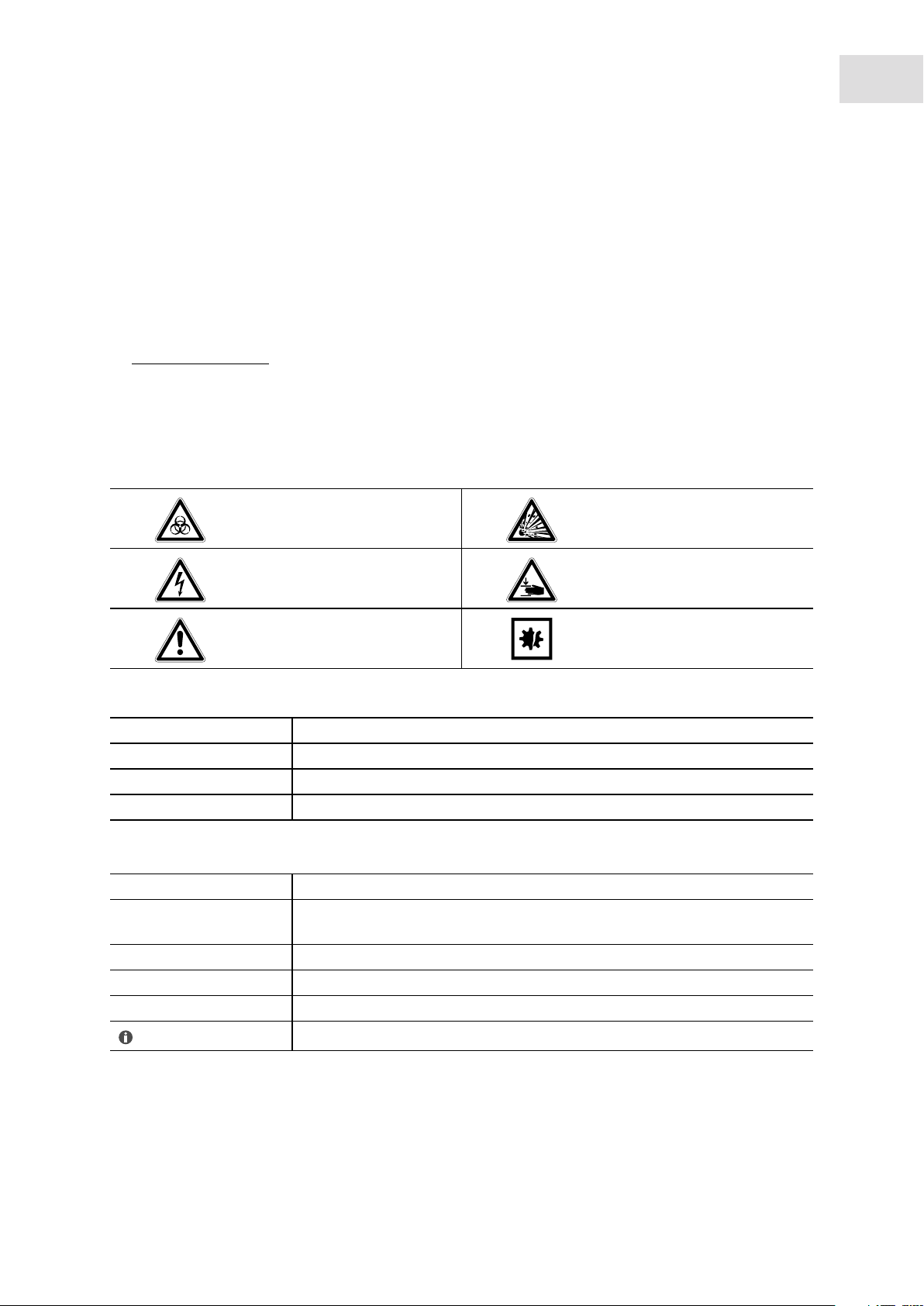
1.2 Danger symbols and danger levels . . . . . . . . . . . . . . . . . . . . . . . . . . . . . . . . . . . . . . . . . . . . . . . . 5
1.2.1 Danger symbols. . . . . . . . . . . . . . . . . . . . . . . . . . . . . . . . . . . . . . . . . . . . . . . . . . . . . . . . 5
1.2.2 Danger levels. . . . . . . . . . . . . . . . . . . . . . . . . . . . . . . . . . . . . . . . . . . . . . . . . . . . . . . . . . 5
1.3 Symbols used . . . . . . . . . . . . . . . . . . . . . . . . . . . . . . . . . . . . . . . . . . . . . . . . . . . . . . . . . . . . . . . . 5
1.4 Abbreviations used . . . . . . . . . . . . . . . . . . . . . . . . . . . . . . . . . . . . . . . . . . . . . . . . . . . . . . . . . . . . 6
2 Product description . . . . . . . . . . . . . . . . . . . . . . . . . . . . . . . . . . . . . . . . . . . . . . . . . . . . . . . . . . . . . . . . 7
2.1 Main illustration . . . . . . . . . . . . . . . . . . . . . . . . . . . . . . . . . . . . . . . . . . . . . . . . . . . . . . . . . . . . . . 7
2.2 Delivery package. . . . . . . . . . . . . . . . . . . . . . . . . . . . . . . . . . . . . . . . . . . . . . . . . . . . . . . . . . . . . . 8
2.3 Features. . . . . . . . . . . . . . . . . . . . . . . . . . . . . . . . . . . . . . . . . . . . . . . . . . . . . . . . . . . . . . . . . . . . . 8
2.4 Rotors . . . . . . . . . . . . . . . . . . . . . . . . . . . . . . . . . . . . . . . . . . . . . . . . . . . . . . . . . . . . . . . . . . . . . . 9
2.4.1 Rotor FA-45-12-17. . . . . . . . . . . . . . . . . . . . . . . . . . . . . . . . . . . . . . . . . . . . . . . . . . . . . . 9
2.4.2 Rotor FA-45-24-11. . . . . . . . . . . . . . . . . . . . . . . . . . . . . . . . . . . . . . . . . . . . . . . . . . . . . 10
2.4.3 Rotor FA-45-24-11-Kit. . . . . . . . . . . . . . . . . . . . . . . . . . . . . . . . . . . . . . . . . . . . . . . . . . 11
2.4.4 Rotors FA-45-30-11 and F-45-30-11 . . . . . . . . . . . . . . . . . . . . . . . . . . . . . . . . . . . . . . . 12
2.4.5 Rotors FA-45-48-11 and F-45-48-11 . . . . . . . . . . . . . . . . . . . . . . . . . . . . . . . . . . . . . . . 13
2.4.6 Rotor F-45-48-5-PCR. . . . . . . . . . . . . . . . . . . . . . . . . . . . . . . . . . . . . . . . . . . . . . . . . . . 14
2.4.7 Rotor S-24-11-AT . . . . . . . . . . . . . . . . . . . . . . . . . . . . . . . . . . . . . . . . . . . . . . . . . . . . . 14
3
3 Safety. . . . . . . . . . . . . . . . . . . . . . . . . . . . . . . . . . . . . . . . . . . . . . . . . . . . . . . . . . . . . . . . . . . . . . . . . . . 15
3.1 Intended use . . . . . . . . . . . . . . . . . . . . . . . . . . . . . . . . . . . . . . . . . . . . . . . . . . . . . . . . . . . . . . . . 15
3.2 User profile . . . . . . . . . . . . . . . . . . . . . . . . . . . . . . . . . . . . . . . . . . . . . . . . . . . . . . . . . . . . . . . . . 15
3.3 Application limits . . . . . . . . . . . . . . . . . . . . . . . . . . . . . . . . . . . . . . . . . . . . . . . . . . . . . . . . . . . . 15
3.3.1 Declaration concerning the ATEX directive (94/9/EC) . . . . . . . . . . . . . . . . . . . . . . . . . 15
3.3.2 Maximum service life for accessories . . . . . . . . . . . . . . . . . . . . . . . . . . . . . . . . . . . . . . 15
3.4 Information on product liability . . . . . . . . . . . . . . . . . . . . . . . . . . . . . . . . . . . . . . . . . . . . . . . . . 16
3.5 Warnings for intended use . . . . . . . . . . . . . . . . . . . . . . . . . . . . . . . . . . . . . . . . . . . . . . . . . . . . . 17
3.5.1 Personal injury or damage to the equipment . . . . . . . . . . . . . . . . . . . . . . . . . . . . . . . . 17
3.5.2 Incorrect handling of the centrifuge . . . . . . . . . . . . . . . . . . . . . . . . . . . . . . . . . . . . . . . 18
3.5.3 Incorrect handling of the rotors . . . . . . . . . . . . . . . . . . . . . . . . . . . . . . . . . . . . . . . . . . 18
3.5.4 Extreme strain on the centrifuging tubes . . . . . . . . . . . . . . . . . . . . . . . . . . . . . . . . . . . 19
3.5.5 Aerosol-tight centrifugation . . . . . . . . . . . . . . . . . . . . . . . . . . . . . . . . . . . . . . . . . . . . . 20
3.6 Safety instructions located on the device . . . . . . . . . . . . . . . . . . . . . . . . . . . . . . . . . . . . . . . . . . 20
4 Installation . . . . . . . . . . . . . . . . . . . . . . . . . . . . . . . . . . . . . . . . . . . . . . . . . . . . . . . . . . . . . . . . . . . . . . 21
4.1 Selecting the location . . . . . . . . . . . . . . . . . . . . . . . . . . . . . . . . . . . . . . . . . . . . . . . . . . . . . . . . . 21
4.2 Preparing installation . . . . . . . . . . . . . . . . . . . . . . . . . . . . . . . . . . . . . . . . . . . . . . . . . . . . . . . . . 21
4.3 Installing the instrument . . . . . . . . . . . . . . . . . . . . . . . . . . . . . . . . . . . . . . . . . . . . . . . . . . . . . . . 22
5 Operation. . . . . . . . . . . . . . . . . . . . . . . . . . . . . . . . . . . . . . . . . . . . . . . . . . . . . . . . . . . . . . . . . . . . . . . . 23
5.1 Overview of operating controls . . . . . . . . . . . . . . . . . . . . . . . . . . . . . . . . . . . . . . . . . . . . . . . . . . 23
5.2 Menu navigation . . . . . . . . . . . . . . . . . . . . . . . . . . . . . . . . . . . . . . . . . . . . . . . . . . . . . . . . . . . . . 25
5.3 Menu . . . . . . . . . . . . . . . . . . . . . . . . . . . . . . . . . . . . . . . . . . . . . . . . . . . . . . . . . . . . . . . . . . . . . . 25
5.4 Preparing for centrifugation . . . . . . . . . . . . . . . . . . . . . . . . . . . . . . . . . . . . . . . . . . . . . . . . . . . . 27
5.4.1 Switching on the centrifuge . . . . . . . . . . . . . . . . . . . . . . . . . . . . . . . . . . . . . . . . . . . . . 27
5.4.2 Inserting the rotor . . . . . . . . . . . . . . . . . . . . . . . . . . . . . . . . . . . . . . . . . . . . . . . . . . . . . 27
5.4.3 Automatic rotor detection . . . . . . . . . . . . . . . . . . . . . . . . . . . . . . . . . . . . . . . . . . . . . . . 27
5.4.4 Replacing the rotor . . . . . . . . . . . . . . . . . . . . . . . . . . . . . . . . . . . . . . . . . . . . . . . . . . . . 27
5.4.5 Loading the rotor . . . . . . . . . . . . . . . . . . . . . . . . . . . . . . . . . . . . . . . . . . . . . . . . . . . . . 28
5.4.6 Closing the rotor lid . . . . . . . . . . . . . . . . . . . . . . . . . . . . . . . . . . . . . . . . . . . . . . . . . . . 30
5.4.7 Closing the centrifuge lid . . . . . . . . . . . . . . . . . . . . . . . . . . . . . . . . . . . . . . . . . . . . . . . 30
Page 4

Table of contents
Centrifuge 5427 R
4
English (EN)
5.5 Cooling . . . . . . . . . . . . . . . . . . . . . . . . . . . . . . . . . . . . . . . . . . . . . . . . . . . . . . . . . . . . . . . . . . . . 30
5.5.1 Set the temperature. . . . . . . . . . . . . . . . . . . . . . . . . . . . . . . . . . . . . . . . . . . . . . . . . . . . 30
5.5.2 Temperature display . . . . . . . . . . . . . . . . . . . . . . . . . . . . . . . . . . . . . . . . . . . . . . . . . . . 30
5.5.3 Temperature monitoring . . . . . . . . . . . . . . . . . . . . . . . . . . . . . . . . . . . . . . . . . . . . . . . . 31
5.5.4 Start FastTemp . . . . . . . . . . . . . . . . . . . . . . . . . . . . . . . . . . . . . . . . . . . . . . . . . . . . . . . 31
5.5.5 Continuous cooling . . . . . . . . . . . . . . . . . . . . . . . . . . . . . . . . . . . . . . . . . . . . . . . . . . . . 32
5.5.6 Endless operation of continuous cooling . . . . . . . . . . . . . . . . . . . . . . . . . . . . . . . . . . . 32
5.6 Centrifuging . . . . . . . . . . . . . . . . . . . . . . . . . . . . . . . . . . . . . . . . . . . . . . . . . . . . . . . . . . . . . . . . 33
5.6.1 Centrifuging with preset time . . . . . . . . . . . . . . . . . . . . . . . . . . . . . . . . . . . . . . . . . . . . 33
5.6.2 Centrifuging in continuous operation . . . . . . . . . . . . . . . . . . . . . . . . . . . . . . . . . . . . . . 34
5.6.3 Short spin centrifugation . . . . . . . . . . . . . . . . . . . . . . . . . . . . . . . . . . . . . . . . . . . . . . . 34
5.6.4 Setting the centrifugation radius . . . . . . . . . . . . . . . . . . . . . . . . . . . . . . . . . . . . . . . . . 35
5.6.5 After centrifugation . . . . . . . . . . . . . . . . . . . . . . . . . . . . . . . . . . . . . . . . . . . . . . . . . . . . 35
5.7 Standby mode . . . . . . . . . . . . . . . . . . . . . . . . . . . . . . . . . . . . . . . . . . . . . . . . . . . . . . . . . . . . . . . 35
6 Maintenance . . . . . . . . . . . . . . . . . . . . . . . . . . . . . . . . . . . . . . . . . . . . . . . . . . . . . . . . . . . . . . . . . . . . . 37
6.1 Prepare cleaning/disinfection . . . . . . . . . . . . . . . . . . . . . . . . . . . . . . . . . . . . . . . . . . . . . . . . . . . 37
6.2 Cleaning/disinfection . . . . . . . . . . . . . . . . . . . . . . . . . . . . . . . . . . . . . . . . . . . . . . . . . . . . . . . . . 37
6.2.1 Cleaning and disinfecting the device . . . . . . . . . . . . . . . . . . . . . . . . . . . . . . . . . . . . . . 38
6.2.2 Cleaning and disinfecting the rotor. . . . . . . . . . . . . . . . . . . . . . . . . . . . . . . . . . . . . . . . 38
6.3 Additional service instructions for Centrifuge 5427 R . . . . . . . . . . . . . . . . . . . . . . . . . . . . . . . . 39
6.4 Glass breakage . . . . . . . . . . . . . . . . . . . . . . . . . . . . . . . . . . . . . . . . . . . . . . . . . . . . . . . . . . . . . . 39
6.5 Replacing fuses . . . . . . . . . . . . . . . . . . . . . . . . . . . . . . . . . . . . . . . . . . . . . . . . . . . . . . . . . . . . . . 40
6.6 Decontamination before shipment . . . . . . . . . . . . . . . . . . . . . . . . . . . . . . . . . . . . . . . . . . . . . . . 40
7 Troubleshooting . . . . . . . . . . . . . . . . . . . . . . . . . . . . . . . . . . . . . . . . . . . . . . . . . . . . . . . . . . . . . . . . . . 41
7.1 General errors . . . . . . . . . . . . . . . . . . . . . . . . . . . . . . . . . . . . . . . . . . . . . . . . . . . . . . . . . . . . . . . 41
7.2 Error messages . . . . . . . . . . . . . . . . . . . . . . . . . . . . . . . . . . . . . . . . . . . . . . . . . . . . . . . . . . . . . . 42
7.3 Emergency release . . . . . . . . . . . . . . . . . . . . . . . . . . . . . . . . . . . . . . . . . . . . . . . . . . . . . . . . . . . 44
8 Transport, storage and disposal . . . . . . . . . . . . . . . . . . . . . . . . . . . . . . . . . . . . . . . . . . . . . . . . . . . . . 45
8.1 Transport. . . . . . . . . . . . . . . . . . . . . . . . . . . . . . . . . . . . . . . . . . . . . . . . . . . . . . . . . . . . . . . . . . . 45
8.2 Storage . . . . . . . . . . . . . . . . . . . . . . . . . . . . . . . . . . . . . . . . . . . . . . . . . . . . . . . . . . . . . . . . . . . . 45
8.3 Disposal. . . . . . . . . . . . . . . . . . . . . . . . . . . . . . . . . . . . . . . . . . . . . . . . . . . . . . . . . . . . . . . . . . . . 45
9 Technical data. . . . . . . . . . . . . . . . . . . . . . . . . . . . . . . . . . . . . . . . . . . . . . . . . . . . . . . . . . . . . . . . . . . . 47
9.1 Power supply. . . . . . . . . . . . . . . . . . . . . . . . . . . . . . . . . . . . . . . . . . . . . . . . . . . . . . . . . . . . . . . . 47
9.2 Ambient conditions . . . . . . . . . . . . . . . . . . . . . . . . . . . . . . . . . . . . . . . . . . . . . . . . . . . . . . . . . . . 47
9.3 Weight/dimensions . . . . . . . . . . . . . . . . . . . . . . . . . . . . . . . . . . . . . . . . . . . . . . . . . . . . . . . . . . . 47
9.4 Application parameters . . . . . . . . . . . . . . . . . . . . . . . . . . . . . . . . . . . . . . . . . . . . . . . . . . . . . . . . 48
9.5 Acceleration times and deceleration times for the Centrifuge 5427 R (according to DIN 58 970)
49
10 Ordering Information . . . . . . . . . . . . . . . . . . . . . . . . . . . . . . . . . . . . . . . . . . . . . . . . . . . . . . . . . . . . . . 51
10.1 Centrifuge 5427 R . . . . . . . . . . . . . . . . . . . . . . . . . . . . . . . . . . . . . . . . . . . . . . . . . . . . . . . . . . . . 51
10.2 Accessories . . . . . . . . . . . . . . . . . . . . . . . . . . . . . . . . . . . . . . . . . . . . . . . . . . . . . . . . . . . . . . . . . 51
10.2.1 Rotors and rotor lids . . . . . . . . . . . . . . . . . . . . . . . . . . . . . . . . . . . . . . . . . . . . . . . . . . . 51
10.2.2 Adapters . . . . . . . . . . . . . . . . . . . . . . . . . . . . . . . . . . . . . . . . . . . . . . . . . . . . . . . . . . . . 52
10.2.3 Other accessories . . . . . . . . . . . . . . . . . . . . . . . . . . . . . . . . . . . . . . . . . . . . . . . . . . . . . 53
10.3 Safety. . . . . . . . . . . . . . . . . . . . . . . . . . . . . . . . . . . . . . . . . . . . . . . . . . . . . . . . . . . . . . . . . . . . . . 53
Page 5
Operating instructions
Centrifuge 5427 R
English (EN)
1 Operating instructions
1.1 Using this manual
Read this operating manual completely before using the device for the first time. Please also note the
operating instructions for the accessories, if applicable.
This operating manual is part of the product. Thus, it must always be easily accessible.
Enclose this operating manual when transferring the device to third parties.
If this manual is lost, please request another one. You will find the current version on our webpage
www.eppendorf.com.
1.2 Danger symbols and danger levels
The safety instructions in this manual appear with the following danger symbols and danger levels:
1.2.1 Danger symbols
Biohazard Explosion
5
Electric shock Crushing
Hazard point Material damage
1.2.2 Danger levels
DANGER Will lead to severe injuries or death.
WARNING Can lead to severe injuries or death.
CAUTION Can lead to light to moderate injuries.
ATTENTION May lead to material damage./Paragraph
1.3 Symbols used
Depiction Meaning
1.
2.
Actions without a specified order
• List:
Text Display or software texts
Actions in the specified order
Additional information
Page 6

Operating instructions
Centrifuge 5427 R
6
English (EN)
1.4 Abbreviations used
NN
Mean sea level (MSL)
PCR
Polymerase chain reaction
RZB/rcf
Relative centrifugal force – g-force in m/s
rpm
Revolutions per minute – in rpm
UV
Ultraviolet radiation
2
Page 7
2 Product description
2.1 Main illustration
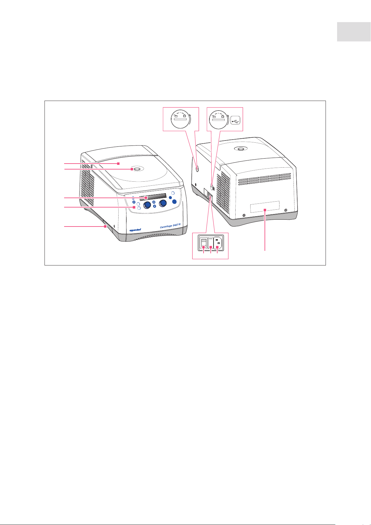
Abb. 2-1: Front and rear view of the Centrifuge 5427 R
1
2
menu
3
4
enter
Product description
Centrifuge 5427 R
7
English (EN)
USB
67
open
t
shor
t
star
op
t
rpm
rcf
ast
f
temp
s
5
8
9 10
11
Fig. 2-1: Front and rear view of the Centrifuge 5427 R
1 Centrifuge lid
2 Monitoring glass
Visual control for rotor stop or speed control
option using stroboscope
3 Display
Display of centrifugation parameters and device
settings (see Fig. 5-2 on p. 24)
4 Control panel
Keys and dials for operating centrifuge (see
Fig. 5-1 on p. 23)
7 USB port
Only for Technical Service: interfaces for error
analyses and software updates
8 Mains/power switch
Switch for switching the device on (I) and off (0)
9 Fuse holder
10 Power connection socket
Connection for supplied power cable
11 Name plate
5 Condensation water tray (only)
6 Emergency release
(see p. 44)
Page 8

Product description
Centrifuge 5427 R
8
English (EN)
2.2 Delivery package
Quant
ity
1 - - See chapter Ordering Information for corresponding device
1 5301 850.249 022654403 4.0 A (230 V), 2 pieces
or 5427 850.341 022654381 8.0 AT UL (120 V/100 V), 2 pieces
or 5811 352.006 022664107 10.0 AT UL (100 V), 2 pieces
1 5416 301.001 022634305 Standard
1- - Mains power cable
1 5409 850.083 Tray for condensation water
1 5409 900.021 5409900021 Languages: EN, DE, FR, ES, IT, PT
1 5409 900.030 5409900030 Languages: DA, FI, EL, NL, SV (only 230 V devices)
Order no.
(International)
Order no.
(North America)
Description
Centrifuge 5427 R
version, equipment and order number
Fuse
Rotor key
Operating Manual Centrifuge 5427 R
2.3 Features
The high-performance Centrifuge 5427 R has a capacity of 48 × 2 mL and maximally reaches 25 001 × g
resp. maximally 16 220 rpm. You can select from 9 different rotors to centrifuge the following tubes for
your various applications:
• Tubes (0.2 mL to 5.0 mL)
• PCR strips
• Microtainers (0.6 ml)
• Spin columns (1.5 mL, 2.0 mL)
The Centrifuge 5427 R has a temperature function for centrifugation at temperatures of-11 °C to 40 °C. The
FastTemp function is used to start a temperature control run without samples in order to quickly bring the
rotor chamber to the set temperature.
Page 9
2.4 Rotors
Eppendorf centrifuges may only be operated with rotors that are intended for use with the
corresponding centrifuge.
Only use rotors which are marked with the name of the centrifuge (e.g., 5427 R).
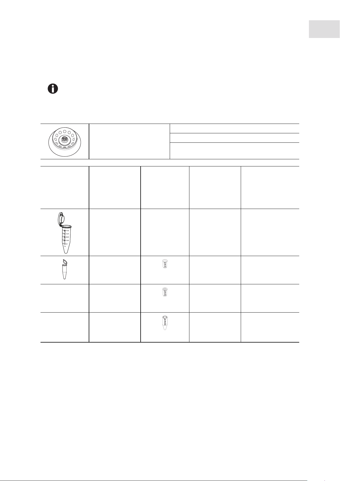
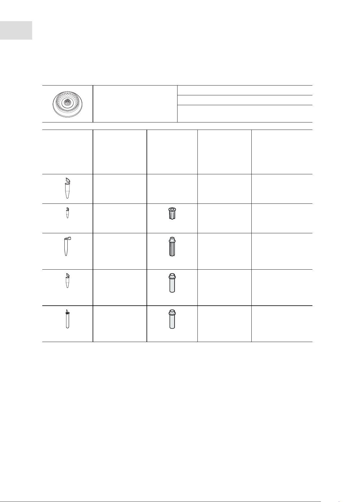
2.4.1 Rotor FA-45-12-17
Max. g-force: 20 598 × g
Rotor FA-45-12-17
Aerosol-tight fixed-angle rotor
for 12 reaction tubes
Vessels Vessel Adapters Adapter base Max. g-force:
Capacity Order no.
(international)
Vessels per
adapter/rotor
Vessel – – 20 598 × g
5 mL Ø 17 mm 14 000 rpm
-/12 9.4 cm
Max. speed: 14 000 rpm
Max. load (adapter, tube
and contents):
Tube diameter Max. speed
Product description
Centrifuge 5427 R
English (EN)
12 × 9.5 g
Centrifugation radius
9
Vessel
1.5 mL/2.0 mL Ø 11 mm 14 000 rpm
1/12 8.0 cm
HPLC vessel
1/12 7.4 cm
Cryo tube
1.0 mL – 2.0 mL Ø 13 mm 14 000 rpm
1/12 8.3 cm
5820 768.002
5820 770.007
5820 769.009
open 17 530 × g
flat 16 215 × g
Ø 11 mm 14 000 rpm
flat 18 188 × g
Page 10
10
Product description
Centrifuge 5427 R
English (EN)
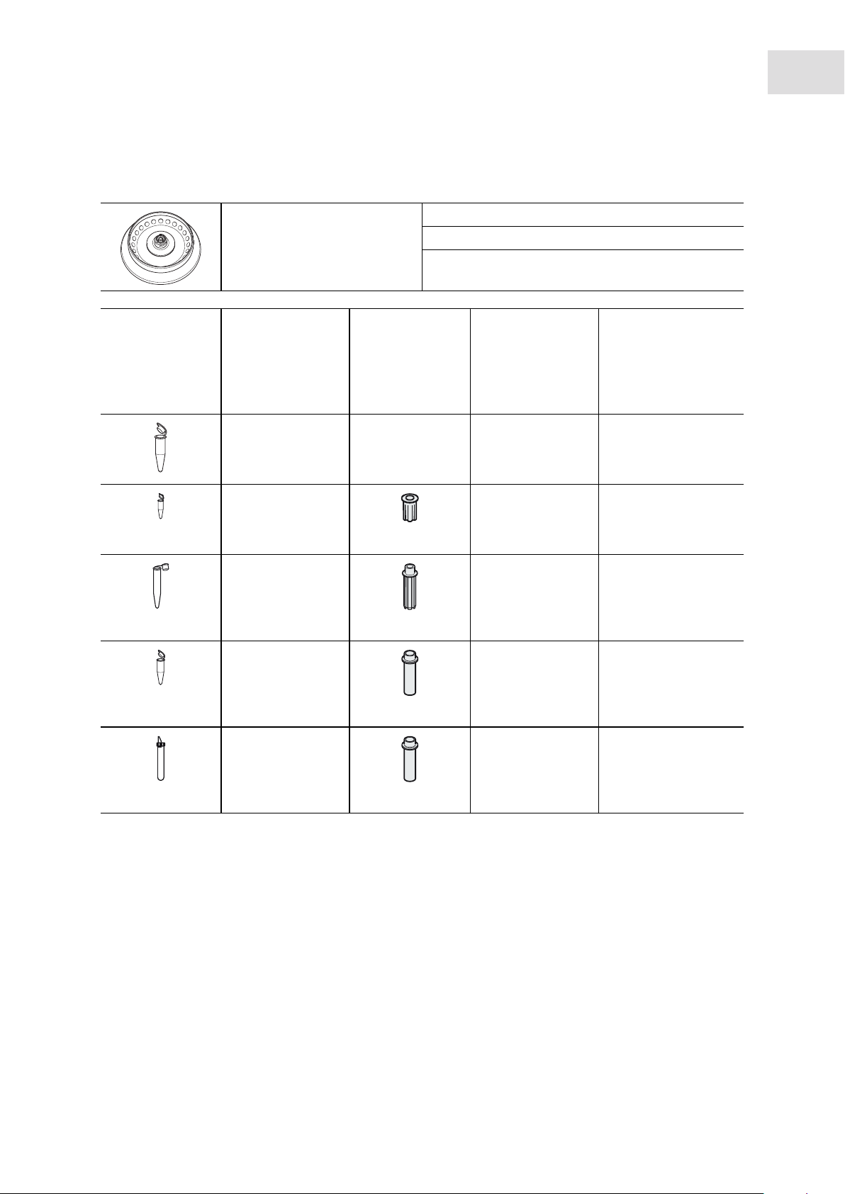
2.4.2 Rotor FA-45-24-11
Max. g-force: 25 001 × g
Rotor FA-45-24-11
Aerosol-tight fixed-angle rotor
for 24 tubes
Vessels Vessel Adapters Adapter base Max. g-force:
Capacity Order no.
(international)
Vessels per
adapter/rotor
Vessel – – 25 001 × g
1.5 mL/2.0 mL Ø 11 mm 16 220 rpm
-/24 8.5 cm
PCR tube
0.2 mL Ø 6 mm 16 220 rpm
1/24 6.4 cm
Vessel
0.4 mL Ø 6 mm 16 220 rpm
1/24 8.5 cm
Vessel
0.5 mL Ø 8 mm 16 220 rpm
1/24 7.4 cm
Microtainers
0.6 mL Ø 8 mm 16 220 rpm
1/24 8.5 cm
5425 715.005
5425 717.008
5425 716.001
5425 716.001
Max. speed: 16 220 rpm
Max. load (adapter, tube
and contents):
Tube diameter Max. speed
conical 18 825 × g
conical 25 001 × g
open 21 766 × g
open 25 001 × g
24 × 3.75 g
Centrifugation radius
Page 11
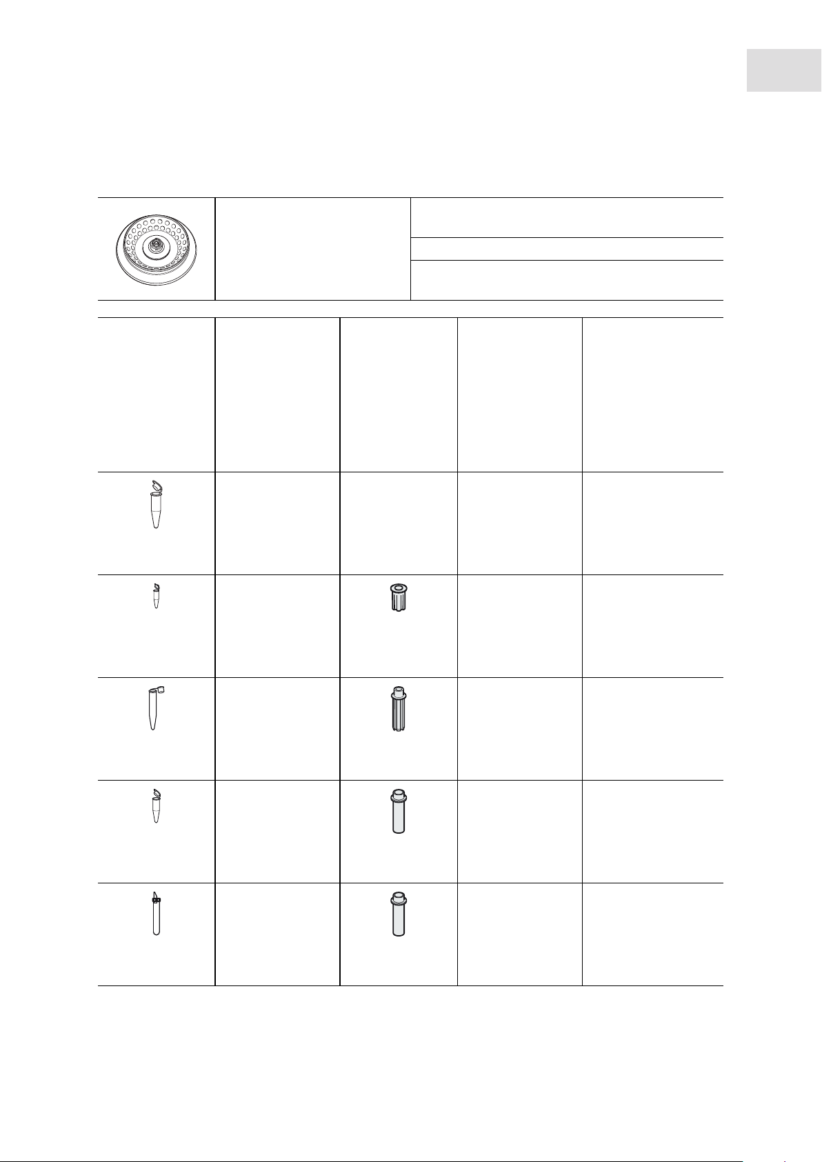
2.4.3 Rotor FA-45-24-11-Kit
Max. g-force: 19 090 × g
Rotor FA-45-24-11-Kit
Aerosol-tight fixed-angle rotor
for 24 tubes
Vessels Vessel Adapters Adapter base Max. g-force:
Capacity Order no.
(international)
Vessels per
adapter/rotor
Vessel – – 19 090 × g
1.5 mL/2.0 mL Ø 11 mm 13 200 rpm
-/24 9.8 cm
PCR tube
0.2 mL Ø 6 mm 13 200 rpm
1/24 7.7 cm
Vessel
0.4 mL Ø 6 mm 13 200 rpm
1/24 9.8 cm
Vessel
0.5 mL Ø 8 mm 13 200 rpm
1/24 8.7 cm
Microtainers
0.6 mL Ø 8 mm 13 200 rpm
1/24 9.8 cm
5425 715.005
5425 717.008
5425 716.001
5425 716.001
Max. speed: 13 200 rpm
Max. load (adapter, tube
and contents):
Tube diameter Max. speed
conical 15 000 × g
conical 19 090 × g
open 16 948 × g
open 19 090 × g
Product description
Centrifuge 5427 R
English (EN)
24 × 3.75 g
Centrifugation radius
11
Page 12

12
Product description
Centrifuge 5427 R
English (EN)
2.4.4 Rotors FA-45-30-11 and F-45-30-11
Rotor FA-45-30-11
Aerosol-tight fixed-angle rotor
for 30 tubes
Rotor F-45-30-11
Fixed-angle rotor for 30 tubes
Vessels Vessel Adapters Adapter base Max. g-force:
Capacity Order no.
(international)
Vessels per
adapter/rotor
Vessel – – 20 817 × g
1.5 mL/2.0 mL Ø 11 mm 14 000 rpm
-/30 9.5 cm
PCR tube
0.2 mL Ø 6 mm 14 000 rpm
1/30 7.4 cm
Vessel
0.4 mL Ø 6 mm 14 000 rpm
1/30 9.5 cm
Vessel
0.5 mL Ø 8 mm 14 000 rpm
1/30 8.4 cm
Microtainers
0.6 mL Ø 8 mm 14 000 rpm
1/30 9.5 cm
5425 715.005
5425 717.008
5425 716.001
5425 716.001
Max. g-force: 20 817 × g
Max. speed: 14 000 rpm
Max. load (adapter, tube
and contents):
Tube diameter Max. speed
conical 16 215 × g
conical 20 817 × g
open 18 407 × g
open 20 817 × g
30 × 3.75 g
Centrifugation radius
Page 13
2.4.5 Rotors FA-45-48-11 and F-45-48-11
Product description
Centrifuge 5427 R
English (EN)
13
FA-45-48-11 rotor
Aerosol-tight fixed-angle rotor
for 48 tubes
Rotor F-45-48-11
Fixed-angle rotor for 48 tubes
Vessels Vessel Adapters Adapter base Max. g-force:
Capacity Order no.
(international)
Vessels per
adapter/rotor
Vessel – – 18 213 × g
1.5 mL/2.0 mL Ø 11 mm 12 700 rpm
-/48 10.1 cm
PCR tube
0.2 mL Ø 6 mm 12 700 rpm
1/48 8 cm
Vessel
0.4 mL Ø 6 mm 12 700 rpm
1/48 10.1 cm
essel
V
0.5 mL Ø
1/48 9 cm
Microtainers
0.6 mL Ø 8 mm 12 700 rpm
1/48 10.1 cm
5425 715.005
5425 717.008
5425 716.001
5425 716.001
Max. g-force: 18 213 × g (outer ring)
16 049 × g (inner ring)
Max. speed: 12 700 rpm
Max. load (adapter, tube
and contents):
Tube diameter Max. speed
conical 14 426 × g
conical 18 213 × g
open 16 229 × g
8 mm 12 700 rpm
open 18 213 × g
48 × 3.75 g
Outer ring
Inner ring
Centrifugation radius
Outer ring
Inner ring
16 049 × g
8.9 cm
12 262 × g
6.8 cm
16 049 × g
8.9 cm
14 065 × g
7.8 cm
16 049 × g
8.9 cm
Page 14
14
Product description
Centrifuge 5427 R
English (EN)
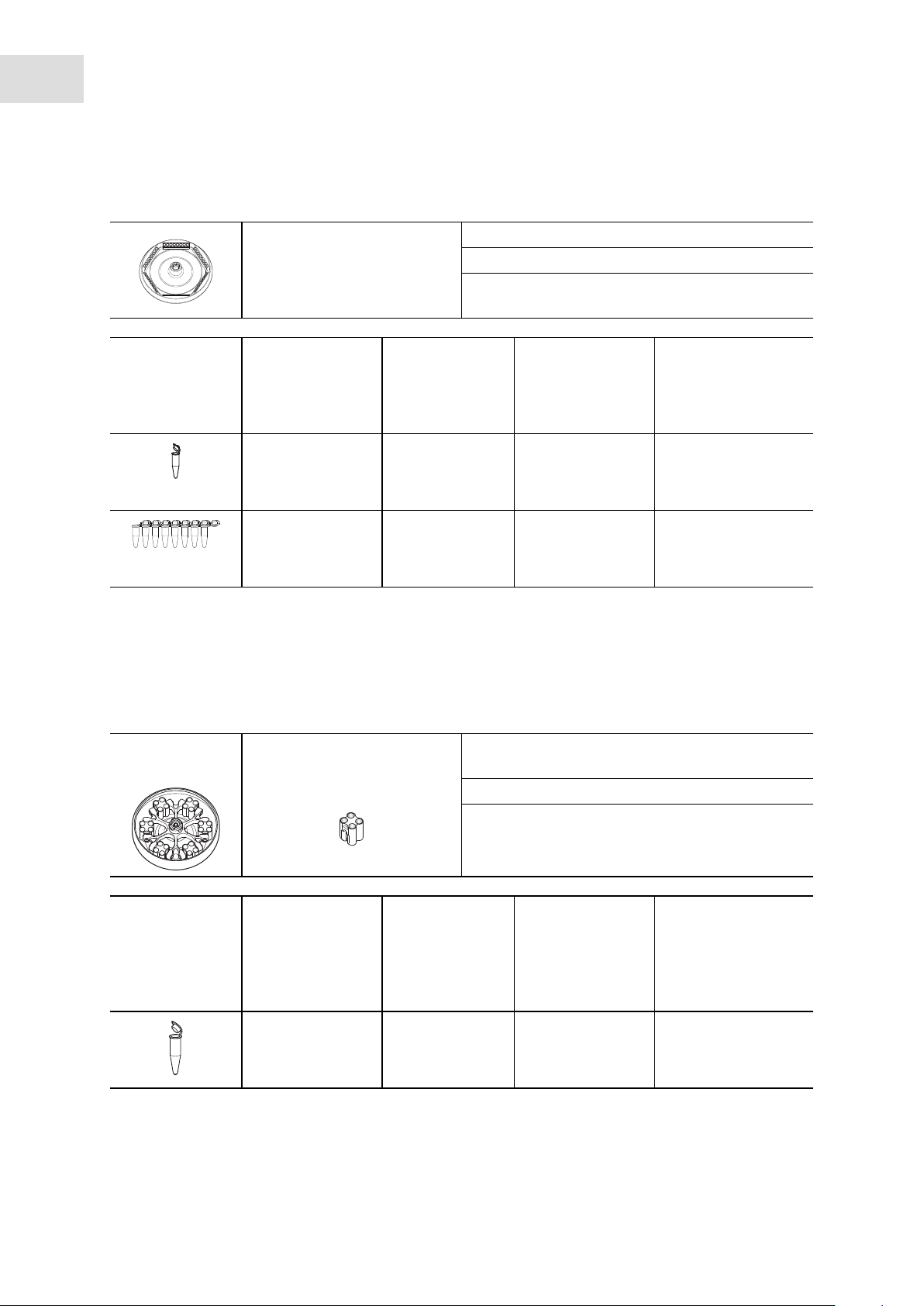
2.4.6 Rotor F-45-48-5-PCR
Rotor F-45-48-5-PCR
Fixed-angle rotor for 48 PCR
tubes
Tubes Tube Adapter Adapter base Max. g-force:
Capacity Tube diameter Max. speed
Tubes per adapter/
rotor
0.2 mL Ø 6 mm 10 500 rpm
–/48 9.5 cm
PCR strips – conical 11 710 × g
0.2 mL Ø 6 mm 10 500 rpm
–/6 × 8 9.5 cm
Max. g-force: 11 710 × g
Max. speed: 10 500 rpm
Max. load (tube and
contents):
– conical 11 710 × g
2.4.7 Rotor S-24-11-AT
This rotor is only intended for use with 1.5 mL/2.0 mL tubes.
The following tubes must not be used in this rotor:
• Adapters for 0.2 mL, 0.4 mL, 0.5 mL and 0.6 mL tubes and the corresponding tubes.
• Spin columns
48 × 0.43 g
Centrifugation radius
Rotor S-24-11-AT Bucket for tubes:
4 × 1.5 mL/2.0 mL
Vessels Vessel Adapters Adapter base Max. g-force:
Capacity Order no.
(international)
Vessels per
adapter/rotor
Vessel – – 16 049 × g
1.5 mL/2.0 mL Ø 11 mm 12 700 rpm
-/24 8.9 cm
Max. g-force: 16 049 × g
Max. speed: 12 700 rpm
Max. load per bucket (tube
and contents):
Tube diameter Max. speed
4 × 3.75 g
Centrifugation radius
Page 15

Safety
Centrifuge 5427 R
English (EN)
3 Safety
3.1 Intended use
The Centrifuge 5427 R is intended exclusively for indoor use and for separating aqueous solutions and
suspensions of various densities in approved test tubes.
3.2 User profile
This device may only be operated by trained specialist staff. They must have carefully read the operating
manual and be familiar with the function of the device.
3.3 Application limits
3.3.1 Declaration concerning the ATEX directive (94/9/EC)
DANGER! Risk of explosion.
Do not operate the device in areas where work is completed with explosive substances.
Do not use this device to process any explosive or highly reactive substances.
Do not use this device to process any substances which may generate an explosive
atmosphere.
15
Due to its design and the environmental conditions inside the device, the Centrifuge 5427 R is not suitable
for use in a potentially explosive atmosphere.
The device only must be used in a safe environment, such as the open environment of a ventilated
laboratory or fume hood. The use of substances which could create a potentially explosive atmosphere is
not permitted. The final decision on the risks associated with the use of these types of substances is the
responsibility of the user.
3.3.2 Maximum service life for accessories
WARNING! Risk of injury from chemically or mechanically damaged accessories.
Even minor scratches and cracks can lead to serious internal material damage.
Protect all accessory parts from mechanical damage.
Inspect the accessories for damage before each use. Replace any damaged accessories.
Do not use rotors, rotor lids or buckets with signs of corrosion or mechanical damage (e.g.,
deformations).
Do not use any accessories whose maximum service life has been exceeded.
CAUTION! Risk of injury due to chemically damaged rotor lids or caps.
Transparent rotor lids or caps made from PC, PP or PEI may lose their strength under the
impact of organic solvents (e.g., phenol, chloroform).
If rotor lids or caps have come into contact with organic solvents, they should be cleaned
immediately.
Regularly check the rotor lids and caps for damages and cracks.
Immediately replace rotor lids or caps that have cracks or milky stains.
Page 16

16
Safety
Centrifuge 5427 R
English (EN)
Beginning with the first commissioning, the following rotors including the corresponding buckets, carriers
and rotor lids have a maximum service life of 7 years or of the number of cycles specified in the table
(depending on what occurs first).
Rotor/accessories Maximum service from commissioning onward
S-24-11-AT (5427 R/5430/5430 R) 75,000 cycles 7 years
FA-45-48-11
(5427 R/5430/5430 R/5804/5804 R/5810/5810 R)
FA-45-12-17 (Centrifuge 5427 R) 75,000 cycles 7 years
QuickLock rotor lid 3 years
Seals of the QuickLock rotor lid 50 autoclaving cycles –
Rotor lid or caps made of polycarbonate ( PC),
polypropylene (PP) or polyetherimide (PEI)
Adapter – 1 year
75,000 cycles 7 years
50 autoclaving cycles 3 years
For all other rotors and rotor lids of this centrifuge there is no service life limit as long as the following
requirements are met:
• Proper use,
• Recommended maintenance
• Undamaged condition
The date of manufacture is stamped on the rotors in the format 03/10 (= March 2010) or on the inside of the
plastic rotor lids in the form of a clock .
To ensure aerosol tightness, the following applies:
• Replace aerosol-tight rotor lids and caps after 50 autoclaving cycles.
• Replace the seal of QuickLock rotor lids after 50 autoclaving cycles.
3.4 Information on product liability
In the following cases, the designated protection of the device may be compromised. Liability for any
resulting property damage or personal injury is then transferred to the operator:
• The device is not used in accordance with the operating manual.
• The device is used outside of its intended use.
• The device is used with accessories or consumables which are not recommended by Eppendorf.
• The device is maintained or repaired by people not authorized by Eppendorf.
• The user makes unauthorized changes to the device.
Page 17

Centrifuge 5427 R
English (EN)
3.5 Warnings for intended use
Read the operating manual and observe the following general safety instructions before using the
Centrifuge 5427 R.
3.5.1 Personal injury or damage to the equipment
WARNING! Electric shock due to damage to device or mains cable.
Only switch on the device if the device and mains cable are undamaged.
Only use devices that have been properly installed or repaired.
In case of danger, disconnect the device from the mains supply by pulling the power plug
from the device or the mains socket or, by using the isolating device intended for this
purpose (e.g. emergency stop switch in the laboratory).
WARNING! Lethal voltages inside the device.
Ensure that the housing is always closed and undamaged so that no parts inside the device
can be contacted by accident.
Do not remove the housing of the device.
Do not allow any liquids to penetrate the inside of the housing.
Do not allow the device to be opened by anyone except service personnel who have been
specifically authorized by Eppendorf.
Safety
17
WARNING! Risk from incorrect supply voltage
Only connect the device to voltage sources which correspond to the electrical
requirements on the name plate.
Only use sockets with a protective earth (PE) conductor and suitable power cable.
WARNING! Damage to health due to infectious liquids and pathogenic germs.
When handling infectious liquids and pathogenic germs, observe the national regulations,
the biological security level of your laboratory, the material safety data sheets, and the
manufacturer's application notes.
Use aerosol tight sealing systems for the centrifugation of these substances.
When working with pathogenic germs belonging to a higher risk group, more than one
aerosol-tight bioseal must be used.
Wear personal protective equipment.
For full instructions regarding the handling of germs or biological material of risk group II
or higher, please refer to the "Laboratory Biosafety Manual" (Source: World Health
Organization, current edition of the Laboratory Biosafety Manual).
WARNING! Risk of injury when opening or closing the centrifuge lid.
There is a risk of crushing your fingers when opening or closing the centrifuge lid.
When opening or closing the centrifuge lid, do not reach between the lid and device or into
the latching mechanism of the lid.
Always open the centrifuge lid completely to prevent it from falling.
Page 18
18
Safety
Centrifuge 5427 R
English (EN)
CAUTION! Poor safety due to incorrect accessories and spare parts.
The use of accessories and spare parts other than those recommended by Eppendorf may
impair the safety, functioning and precision of the device. Eppendorf cannot be held liable or
accept any liability for damage resulting from the use of incorrect or non-recommended
accessories and spare parts, or from the improper use of such equipment.
Only use accessories and original spare parts recommended by Eppendorf.
NOTICE! Damage to device due to spilled liquids.
1. Switch off the device.
2. Disconnect the device from the power supply.
3. Carefully clean the device and the accessories in accordance with the cleaning and
disinfection instructions in the operating manual.
4. If a different cleaning and disinfecting method is to be used, contact Eppendorf AG to
ensure that the intended method will not damage the device.
NOTICE! Damage to electronic components due to condensation.
Condensate can form in the device after it has been moved from a cool environment to a
warmer environment.
After installing the device, wait for at least 4 h. Only then connect the device to the mains
power supply.
3.5.2 Incorrect handling of the centrifuge
NOTICE! Damage from knocking against or moving the device during operation.
If the rotor bangs against the rotor chamber wall, it will cause considerable damage to the
device and rotor.
Do not move or knock against the device during operation.
3.5.3 Incorrect handling of the rotors
WARNING! Risk of injury from improperly attached rotors and rotor lids.
Only centrifuge with rotor and rotor lid firmly tightened.
If unusual noises occur when the centrifuge starts, the rotor or the rotor lid may not be
properly secured. Immediately press the start/stop key to stop centrifuging.
CAUTION! Risk of injury due to asymmetric loading of a rotor.
Load rotors symmetrically with identical tubes.
Only load adapters with suitable tubes.
Always use the same type of tubes (weight, material/density and volume).
Check symmetric loading by balancing the adapters and tubes used with scales.
Page 19

Safety
Centrifuge 5427 R
English (EN)
CAUTION! Risk of injury from overloaded rotor.
The Centrifuge 5427 R is designed for the centrifugation of material with a max. density of 1.2
g/mL at maximum speed and filling volume and/or load.
Do not exceed the maximum load of the rotor.
NOTICE! Damage to rotors from aggressive chemicals.
Rotors are high-quality components which withstand extreme stresses. This stability can be
impaired by aggressive chemicals.
Avoid using aggressive chemicals, including strong and weak alkalis, strong acids,
solutions with mercury, copper and other heavy metal ions, halogenated hydrocarbons,
concentrated saline solutions and phenol.
Due to the manufacturing process, color variations may occur on rotors marked "coated".
These color variations do not effect service life or resistance to chemicals.
NOTICE! If handled incorrectly, the rotor can fall over.
The rotor can fall over if the buckets are used as a handle.
Remove the buckets before inserting and/or removing a swing-bucket rotor.
Always use both hands to carry the rotor cross.
19
3.5.4 Extreme strain on the centrifuging tubes
CAUTION! Risk of injury from overloaded tubes.
Note the loading limits specified by the tube manufacturer.
Only use tubes which are approved by the manufacturer for the required rcf.
NOTICE! Risk from damaged tubes.
Damaged tubes must not be used, as this could cause further damage to the device and the
accessories and loss of the samples.
Before use, visually check all of the tubes for damage.
NOTICE! Risk from open tube lids.
Open tube lids can brake off during centrifugation and damage the rotor and the centrifuge.
Carefully seal all tube lids before centrifuging.
Exception: Note the information on the centrifugation of spin columns in the rotor
FA-45-24-11-Kit (see Preparing for centrifugation on p. 27).
NOTICE! Hazard to plastic tubes from organic solvents.
The density of plastic tubes is reduced when organic solvents (e.g., phenol, chloroform) are
used, i.e. the tubes could become damaged.
Observe the manufacturer's specifications for chemical resistance of the tubes.
Page 20
20
Safety
Centrifuge 5427 R
English (EN)
3.5.5 Aerosol-tight centrifugation
WARNING! Risk to health due to limited aerosol tightness with incorrect rotor/rotor lid
combination.
Aerosol-tight centrifugation is guaranteed only if the rotors and rotor lids intended for this
purpose are used. The designation of aerosol-tight fixed-angle rotors always starts with
FA.The aerosol-tight rotors and rotor lids of this centrifuge are additionally marked with a red
ring on the rotor and a red rotor lid screw.
Aerosol-tight swing-bucket rotors are marked with AT (aerosol-tight).
For aerosol-tight centrifugation, always simultaneously use rotors and rotor lids which are
marked as aerosol-tight in the centrifuge intended for the corresponding purpose. The
details specifying in which centrifuge you may use the aerosol-tight rotors and rotor lids
can be found on the rotor and, beginning from production date of October 2003, on the
upper side of the rotor lid.
Only use aerosol-tight rotor lids in combination with rotors which are marked on the rotor
lid.
WARNING! Damage to health as a result of limited aerosol tightness and incorrect usage.
Autoclaving, mechanical stresses and contamination by chemicals or other aggressive
solvents can impair the aerosol-tightness of the rotors and rotor lids.
Check the integrity of the seals of the aerosol-tight rotor lids or caps before each use.
Only use aerosol-tight rotor lids or caps if the seals are undamaged and clean.
Lightly grease the threads of the rotor lid screw with pivot grease after every proper
autoclaving (121 °C, 20 min.) (int. order no. Int. 5810 350.050, North America
022634330).
Replace aerosol-tight rotor lids and caps after 50autoclaving cycles.
For QuickLock rotor lids, the seal must be replaced after 50 autoclaving cycles.
Never store aerosol-tight rotors or buckets closed.
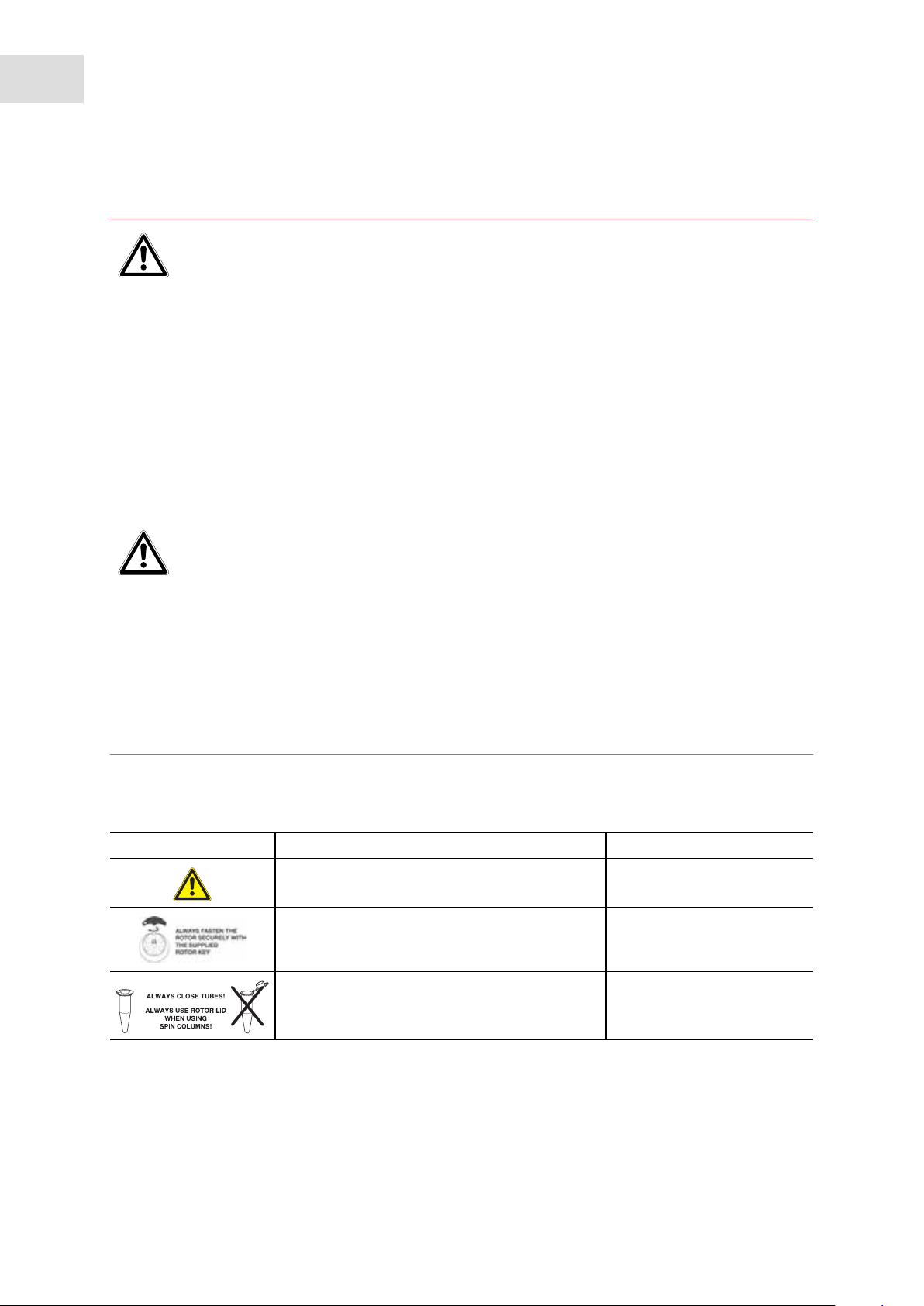
3.6 Safety instructions located on the device
Display Meaning Location
Hazard point Right side of the device
CAUTION
Always tighten the rotor using the supplied rotor
key.
CAUTION
Close all tubes and use a rotor lid.
Top of device, below the
centrifuge lid
Top of device, below the
centrifuge lid
Page 21

4 Installation
4.1 Selecting the location
NOTICE! If an error occurs, the objects in the immediate proximity of the device will be
damaged.
In accordance with recommendations in EN 61010-2-020, leave a safety clearance of
30 cm around the device during operation.
Please remove all materials and objects from this area.
NOTICE! Damage from overheating.
Do not install the device near heat sources (e.g. heating, drying cabinet).
Do not expose the device to direct sunlight.
Ensure unobstructed air circulation. Maintain a clearance of at least 30 cm (11.8 in)
around all ventilation grilles.
Installation
Centrifuge 5427 R
English (EN)
21
Select the location for the device according to the following criteria:
• Suitable power connection as per the name plate (230 V/120 V/100 V).
• Stable, horizontal and resonance-free lab bench.
• A well ventilated environment which is protected from direct sunlight to prevent the device from heating
up more.
4.2 Preparing installation
Prerequisites
The weight of the centrifuge is 30.0 kg (66.14 lb). For unpacking and installation the assistance of another
person is required.
Perform the following steps in the sequence described.
1. Open the box.
2. Remove the accessories.
3. The centrifuge must be lifted from the box by two people.
4. Remove the transport securing device from the sides.
5. Place the device on a suitable lab bench.
Do not use the opening for the condensation water tray as a handle.
6. Remove the plastic sleeve.
Page 22

22
Installation
Centrifuge 5427 R
English (EN)
4.3 Installing the instrument
Prerequisites
The device is on a suitable lab bench.
NOTICE! Damage to electronic components due to condensation.
Condensate can form in the device after it has been moved from a cool environment to a
warmer environment.
After installing the device, wait for at least 4 h. Only then connect the device to the mains
power supply.
NOTICE! Centrifuge 5427 R: compressor damage after improper transport.
Only switch on the centrifuge 4 h after installation.
Perform the following steps in the sequence described.
1. Let the device warm up to ambient temperature.
2. Check that the mains voltage and frequency match the requirements on the device type plate.
3. Connect the centrifuge to the mains and switch it on using the mains/power switch.
• Display is active.
• Lid opens automatically
4. Remove the transport securing device of the lid latch.
5. Remove the transport securing device of the motor shaft.
6. Use the details included in the scope of delivery to check that the delivery is complete.
7. Check all parts for any transport damage. Contact your dealer if any damage is found.
8. Insert the condensation water tray into the holder provided (see Fig. 2-1 on p. 7).
Retain the packaging material and the transport protection device for subsequent transport or
storage. See also the instructions relating to transport (see p. 45).
Page 23

Centrifuge 5427 R
5 Operation
5.1 Overview of operating controls
Before using the Centrifuge 5427 R, familiarize yourself with the display and operating controls.
Abb. 5-1: Operator panel of the Centrifuge 5427 R
1 2
3 5
4
Operation
23
English (EN)
time
temp
speed
Fig. 5-1: Operator panel of the Centrifuge 5427 R
1 Call and select the menu parameters
(see Menu navigation on p. 25)
2 Switch display of centrifugation speed (rpm or
rcf)
3 Display
4 Short spin centrifugation
(see Short spin centrifugation on p. 34)
7 Set speed of centrifugation
8 Set temperature
9 Set centrifugation time
10 Start FastTemp temperature control run
(see Start FastTemp on p. 31)
11 Select menu item
(see Menu navigation on p. 25)
5 Release lid
6791010 8
6 Start and stop centrifugation
Please also read the precise description of the individual menu functions (see p. 25).
Page 24

24
Operation
Centrifuge 5427 R
English (EN)
Abb. 5-2: Display of the Centrifuge 5427 R.
314 5
2
9
Fig. 5-2: Display of the Centrifuge 5427 R.
1 Centrifugation time
2 Key lock
Key lock. Centrifugation parameters cannot be
accidentally changed.
No key lock. Centrifugation parameters can
be changed.
6
6 g-force (rcf) or speed (rpm)
(see Rotors on p. 9)
7 Status of centrifuge
: Centrifuge lid unlocked.
: Centrifuge lid locked.
(Flashing): Centrifuging in progress.
7
8
3 Start of run time: ATSET function
Start of run time after reaching 95 % of the
specified g-force (rcf) or speed (rpm).
Immediate start of run time.
4 Temperature
5 Soft ramp
Rotor accelerates and brakes slowly.
No symbol: fast acceleration and braking of rotor.
8 Display of centrifugation speed
rcf g-force (relative centrifugal acceleration).
rpm speed (revolutions per minute).
9 Status of speaker
Speaker switched on.
Speaker switched off.
Page 25

5.2 Menu navigation
Proceed as follows to change settings in the device menu:
1. Open the menu.
2. Select the desired menu item.
3. Confirm your selection.
4. Select the setting of the corresponding parameters.
Operation
Centrifuge 5427 R
English (EN)
25
5.
6. Exit the menu.
Confirm the changed setting.
The BACK menu item belonging to the first menu level appears.
To exit the second menu level without changing a parameter, select the BACK menu item and
confirm with menu/enter.
5.3 Menu
Tab. 5-1: Menu structure of the Centrifuge 5427 R.
Menu level 1 (M 1) Menu level 2 (M 2) Display
SOFT
Soft ramp: decreases acceleration speed
and braking speed
Disabled with short spin centrifugation
RAD
For the internal conversion of speed (rpm)
to g-force (rcf), the radius is dependent on
the adapter used.
LOCK
Key lock: centrifugation parameters
(temperature, g-force (rcf) or speed (rpm))
cannot be accidentally changed.
On Rotor accelerates and brakes slowly.
OFF Rotor accelerates and brakes rapidly.
0_2ML
0_4ML
0_5ML
0_6ML
MAX Largest radius of the used rotor.
On Set the centrifugation parameters
OFF
Select the radius according to the adapter
used.
Only rotor FA-45-12-17:
MAX
1_5/2
HPLC
CRYO
permanently. SAFE appears in the display
when the time, temp or speed keys are
pressed.
ATSET
Set start of centrifuging run time.
On The set run time will be counted down
after 95 % of the specified g-force (rcf) or
speed (rpm) has been reached.
OFF The set time is counted down immediately.
Page 26

26
Operation
Centrifuge 5427 R
English (EN)
Menu level 1 (M 1) Menu level 2 (M 2) Display
SHORT
Set the speed of the short spin
centrifugation.
No SOFT function with short spin
centrifugation.
Temp
Set the time limit for continuous cooling
("ECO shut-off") (see p. 30).
Alarm
Switch the loudspeaker on or off.
MAX Short spin centrifugation at the maximum
speed of the inserted rotor
Set Short spin centrifugation with set speed
(g-force (rcf) or speed (rpm)).
8 h Default setting: Continuous cooling ends
after 8 h.
1 h
2 h
4 h
oo Endless operation of continuous cooling.
On Switch on loudspeaker.
OFF Switch off loudspeaker.
To limit continuous cooling after a run to
1 h, 2 h, or 4 h, the centrifuge lid must be
opened and closed again after the run.
VOL
Set the volume.
SLEEP
Switch the standby mode on or off.
If the centrifuge has not been used for
15 min, it will switch to standby. EP then
appears in the display.
Press a key or close the centrifuge lid to
exit the standby mode.
The Back menu item can also be found in both menu levels.
Back in menu level 2: return to menu level 1.
Back in menu level 1: exit menu.
VOL1
…
VOL5
On Standby mode activated.
OFF Standby mode deactivated.
The volume of the loudspeaker can be set
to 5 levels (VOL1 to VOL5). The
loudspeaker must be switched on for the
adjustment to be audible.
Page 27

Operation
Centrifuge 5427 R
English (EN)
5.4 Preparing for centrifugation
5.4.1 Switching on the centrifuge
Switch the centrifuge on using the mains/power switch.
The centrifuge lid opens automatically after switching on using the mains/power switch.
The parameter settings of the last run are displayed.
5.4.2 Inserting the rotor
1. Fit the rotor vertically on the motor shaft.
2. Insert the supplied rotor key into the rotor nut.
3. Turn rotor key clockwise until the rotor nut is firmly tightened.
5.4.3 Automatic rotor detection
The centrifuge has automatic rotor detection. It detects a newly inserted rotor and displays the
name of the rotor for 2 s. g-force (rcf) and speed (rpm) are automatically limited to the
maximum permitted value for the rotor.
Manually turn the rotor counterclockwise to trigger rotor detection.
• The name of the rotor appears in the display.
• The g-force (rcf) and speed (rpm) are automatically limited to the maximum permissible value for the
rotor.
27
5.4.4 Replacing the rotor
1. Turn the rotor nut counterclockwise using the supplied rotor key.
2. Remove the rotor by lifting it vertically.
3. Vertically place another rotor on the motor shaft.
4. Insert the supplied rotor key into the rotor nut.
5. Turn rotor key clockwise until the rotor nut is firmly tightened.
6. In order to trigger the rotor detection, turn the rotor counterclockwise by hand.
• The name of the rotor appears in the display.
• The g-force (rcf) and speed (rpm) are automatically limited to the maximum permissible value for the
rotor.
Rotor detection can also be triggered by short spin centrifugation:
Press the short key until the name of the rotor appears in the display.
Error message after rotor change
• If you start centrifuging immediately after a rotor change, the centrifuge has not carried
out an automatic rotor detection yet. The speed set for the previous rotor may exceed the
maximum permitted speed for the new rotor. In this case, the centrifuge stops after the
automatic rotor detection and displays SPEED. The new maximum permitted speed
appears in the display. You can then restart the centrifuging with this setting or adjust the
speed as necessary.
After each rotor change, check whether the new rotor is detected by the device. Check the
set g-force (rcf) or speed (rpm) and adjust it if necessary.
Page 28

28
Operation
Centrifuge 5427 R
English (EN)
5.4.5 Loading the rotor
5.4.5.1 Loading a fixed-angle rotor
CAUTION! Risk of injury due to asymmetric loading of a rotor.
Load rotors symmetrically with identical tubes.
Only load adapters with suitable tubes.
Always use the same type of tubes (weight, material/density and volume).
Check symmetric loading by balancing the adapters and tubes used with scales.
CAUTION! Risk from damaged or overloaded tubes.
When loading the rotor, observe the safety precautions on dangers as a result of
overloaded or damaged tubes (see Warnings for intended use on p. 17).
Use matching rotor lids
• Fixed-angle rotors may only be operated with the appropriate rotor lid in each case. The
rotor name on the rotor must be the same as the name on the rotor lid.
• To carry out an aerosol-tight centrifugation, an aerosol-tight rotor (label: red ring) and the
corresponding aerosol-tight rotor lid (label: aerosol-tight and red lid screw) must be used.
The device automatically detects imbalances during operation and stops the run immediately
with an error message and a signal tone.
Check the load, balance the tubes and restart the run.
To load the rotor, proceed as follows:
1. Check the maximum payload (adapter, tube and contents) for each rotor bore.
The information about this can be found on every rotor and in this operating manual (see Rotors on p. 9).
2. Load rotors and adapters only with the tubes intended for them.
3. Insert sets of two tubes in the opposite bores of the rotor. To ensure symmetric loading, tubes that are
arranged opposite each other must be of the same type and contain the same filling quantity.
To minimize weight differences between filled sample tubes, we recommend taring with a scale. This
will reduce wear on the drive and reduce running noise.
Page 29

Operation
Centrifuge 5427 R
English (EN)
Spin columns
For centrifuging spin columns in the rotor FA-45-24-11-Kit, you can leave the tube lids open.
However, this can only be done using the tubes provided by kit manufacturers for this
purpose. For reliable centrifugation, you must lean the open tube lids against the edge of the
rotor. Ensure that the lids do not protrude past the edge of the rotor in the process, then attach
the matching rotor lid.
5.4.5.2 Loading a swing-bucket rotor
Prerequisites
• Use a rotor, bucket and adapter combination that is approved by Eppendorf.
• The carriers are sorted by weight category. Carriers located opposite each other must belong to the
same weight category. This is laterally engraved in the groove: e.g., 68 (the last two digits in grams). For
repeat orders, please specify the weight class.
• Matched and checked tubes
29
To load the rotor, proceed as follows:
1. Check the bucket grooves for cleanliness and lightly lubricate them with pivot grease (int. order
no.: 5810 350.050 / North America: 022634330).
Contaminated grooves and pegs prevent a uniform swinging of the bucket.
2. Hang the buckets into the rotor.
All rotor positions must be loaded with carriers.
3. Check that all carriers are hanging properly and can swing freely.
4. Check the maximum payload (adapter, tube and contents) for each bucket.
The details on the maximum payload can be found on the rotor and in this operating manual (see Rotors
on p. 9).
5. Load the buckets symmetrically.
Abb. 5-3: Incomplete, but symmetric loading of the buckets. The pegs of each bucket must be uniformly loaded.
Fig. 5-3: Incomplete, but symmetric loading of the buckets. The pegs of each bucket must be uniformly
loaded.
The supply shown on the right side is incorrect because it does not allow the bucket to properly swing
out.
Page 30

30
Operation
Centrifuge 5427 R
English (EN)
5.4.6 Closing the rotor lid
1. Only QuickLock rotor lid: check that the external sealing ring correctly fits in the groove.
2. Vertically fit the rotor lid on the rotor.
3. Turn the rotor lid screw clockwise to seal the rotor.
Only QuickLock rotor lid:
Turn the rotor lid screw clockwise as far as it will go, until an audible "click" can be heard. The rotor is
not properly closed until an audible click is heard!
5.4.7 Closing the centrifuge lid
WARNING! Risk of injury when opening or closing the centrifuge lid.
There is a risk of crushing your fingers when opening or closing the centrifuge lid.
When opening or closing the centrifuge lid, do not reach between the lid and device or into
the latching mechanism of the lid.
Always open the centrifuge lid completely to prevent it from falling.
1. Check the correct attachment of the rotor and rotor lid.
2. Press the centrifuge lid down until it is gripped by the lid latch.
The lid will be automatically closed and the locking mechanism can be clearly heard.
The open key lights up blue. The display shows the symbol.
5.5 Cooling
The centrifuge cools or maintains the set temperature is the following requirements are met:
• The centrifuge is switched on.
• The centrifuge lid is closed.
• Only with continuous cooling: The set temperature is lower than the ambient temperature.
If the rotor stops (continuous cooling), cooling is slower than during centrifugation or a
temperature control run.
5.5.1 Set the temperature
1. To set the temperature, use the temp arrow keys to select a temperature between -11 °C and 40 °C.
2. Set the run time and g-force (rcf) or speed (rpm). Press the start/stop key to start the centrifugation.
The temperature can be changed during centrifugation.
5.5.2 Temperature display
Temperature display if the rotor stops Set temperature
Temperature display during centrifugation Actual temperature
Page 31

Operation
Centrifuge 5427 R
English (EN)
5.5.3 Temperature monitoring
After the set temperature has been reached, the centrifuge reacts to temperature deviations during
centrifugation as follows:
Deviation from target temperature Action
±3 °C Temperature display flashes.
±5 °C Display shows Err 18. Centrifugation is stopped automatically.
5.5.4 Start FastTemp
With the FastTemp function, you can immediately start a temperature run without samples, at rotor-specific
or temperature-specific speeds. This will quickly bring the rotor chamber, including rotor and adapter, up
to the set target temperature.
Prerequisites
• The centrifuge is switched on.
• Rotor and rotor lid are correctly mounted.
• The centrifuge lid is closed.
• The temperature and g-force (rcf) or speed (rpm) have been set for the upcoming centrifugation (see
Centrifuging on p. 33).
31
1. Press the fast temp key.
The display shows
• FT
• Actual temperature in the rotor chamber
• g-force (rcf) or speed (rpm)
The temperature control run FastTemp automatically ends when the target temperature has been
reached. A periodic signal tone sounds.
2. Press the start/stop key to end the temperature control run early.
• The centrifuge only stops the run once the rotor has reached the set temperature.
Therefore, there may be a delay of approx. 15 min (rotor S-24-11-AT: 30 min) between the
display indicating the set temperature has been reached and the automatic end of the
temperature control run.
Page 32

32
Operation
Centrifuge 5427 R
English (EN)
5.5.5 Continuous cooling
Continuous cooling
Continuous cooling maintains the rotor chamber at the set temperature if the rotor stops.
• During continuous cooling the display shows the set temperature.
• To prevent the rotor chamber from freezing or condensation from forming, the temperature does not go
below 4 °C , irrespective of the set temperature.
• If the rotor stops, temperature control is slower than during centrifugation or a temperature control run.
ECO shut-off
Continuous cooling is switched off if the centrifuge is not used for longer than the preset time. The
centrifuge switches to standby mode.
• Default setting: Continuous cooling ends after 8 h.
• Continuous cooling can be limited to 1 h, 2 h or 4 h.
• ECO shut-off can be switched off (continuous cooling set to endless operation).
Limit continuous cooling to 1 h (2 h, 4 h).
1. Press the menu/enter key.
2. Select TEMP using the arrow key. Confirm with the menu/enter key.
3. Select 1 h (2 h, 4 h) using the arrow key. Confirm with the menu/enter key.
4. To activate ECO shut-off after 1 h, 2 h or 4 h, open and close again the centrifuge lid after the end of the
run.
The device switches to standby mode after 1 h, 2 h or 4 h. The display shows EP.
• If the centrifuge lid is not opened and closed again after the run, ECO shut-off engages
after 8 h (default setting).
• Open the centrifuge lid to end continuous cooling early.
5.5.6 Endless operation of continuous cooling
The ECO shut-off function can be switched off. Continuous cooling is changed to endless operation.
• Endless operation can shorten the service life of the compressor.
• The rotor chamber may freeze.
1. Press the menu/enter key.
2. Select TEMP using the arrow key. Confirm with the menu/enter key.
3. Select oo using the arrow key. Confirm with the menu/enter key.
Ending continuous cooling
4. Open the centrifuge lid to end continuous cooling.
Page 33

Operation
Centrifuge 5427 R
English (EN)
5.6 Centrifuging
CAUTION! Risk from incorrectly-loaded rotors and damaged/overloaded tubes!
Before commencing centrifugation, follow the safety instructions relating to risks from
asymmetrically loaded and/or overloaded rotors and from overloaded, damaged and/or
open tubes (see Warnings for intended use on p. 17).
WARNING! Risk of injury from improperly attached rotors and rotor lids.
Only centrifuge with rotor and rotor lid firmly tightened.
If unusual noises occur when the centrifuge starts, the rotor or the rotor lid may not be
properly secured. Immediately press the start/stop key to stop centrifuging.
Before using the Centrifuge 5427 R for the first time, familiarize yourself with the operating controls and
the display (see Overview of operating controls on p. 23).
Each of the centrifuging variants described here must be preceded by the preparation described above (see
Preparing for centrifugation on p. 27).
Please also note the instructions on cooling (see p. 30).
33
5.6.1 Centrifuging with preset time
Perform the following steps in the sequence described.
1. Use time to set the run time.
2. Use temp to set the temperature.
3. Use speed to set the g-force (rcf) or speed (rpm).
4. Press start/stop to start the centrifugation.
During centrifugation
• blinks in the display when the rotor is running.
• The current actual temperature will be displayed.
• The current g-force (rcf) resp. speed (rpm) of the rotor is displayed.
• The fast temp, open, short keys and the device menu are blocked during centrifugation.
• The total run time, temperature and speed (rpm) can be changed during the run. The display can be
switched between g-force (rcf) and speed (rpm).
• You can also terminate the centrifugation before the set run time has elapsed by pressing the start/
stop key.
End of centrifugation
• After completion of the set time, the centrifuge stops automatically. During braking the elapsed
centrifugation time is displayed flashing. When the rotor stops a signal tone is heard.
• The centrifuge lid remains closed to maintain the sample temperature. You can open it by pressing
the open key.
During the run you can modify the total run time, the temperature and the g-force (rcf)/
speed (rpm).
The values on the display blink while changes are being made. The new parameters are
adopted immediately. If the time is changed during a run, the elapsed time will be subtracted
from this value. Please note that the shortest new total run time that can be set must be 2 min
longer than the elapsed time.
When using adapters, you can adjust the radius.
Page 34

34
Operation
Centrifuge 5427 R
English (EN)
5.6.2 Centrifuging in continuous operation
Perform the following steps in the sequence described.
1. Use time to set the continuous run.
The continuous run function can be set above 9:59 h or below 10 s. The timer shows oo to indicate
continuous operation.
2. Use temp to set the temperature.
3. With speed, set the g-force (rcf) or speed (rpm).
4. Press the start/stop key to start the centrifugation.
The symbol blinks in the display when the rotor is running.
5. Press the start/stop key to end the centrifugation.
• During the braking process, centrifugation time flashes in the display.
• When the rotor stops a signal tone is heard.
• The centrifuge lid remains closed to maintain the sample temperature. You can open it by pressing
the open key.
5.6.3 Short spin centrifugation
Prerequisites
In the SHORT menu, the user sets whether the short spin centrifugation runs with the maximum
g-force (rcf) or speed (rpm) of the inserted rotor (MAX) or with a freely selected speed (SET).
The short spin centrifugation runs as long as the short key is pressed.
1. Only with short spin centrifugation with a set speed: set the g-force (rcf) or speed (rpm) using the speed
arrow keys.
2. Use the temp arrow keys to adjust the temperature.
3. Start short spin centrifugation: hold the short key pressed down.
• The symbol blinks in the display when the rotor is running.
• All other keys are disabled during short spin centrifugation.
4. End short spin centrifugation: release the short key.
• During the braking process, centrifugation time flashes in the display.
• The centrifuge lid remains closed to maintain the sample temperature. Press the open key to open
the lid.
During the braking process, the short spin centrifugation can be restarted up to two times by
pressing the short key again.
The soft ramp is disabled during short spin centrifugation.
Page 35

Operation
Centrifuge 5427 R
English (EN)
5.6.4 Setting the centrifugation radius
If an adapter for tubes is used in a rotor, this changes the centrifugation radius. In the RAD menu item, the
parameter for the tube/adapter combination has to be set.
Prerequisites
• Rotor is inserted.
• The centrifuge has detected the rotor (see Automatic rotor detection on p. 27).
1. Press the menu/enter key.
2. Select the RAD menu item using the arrow key. Confirm with the menu/enter key.
In the RAD menu item, the parameters for the rotor-specific tube/adapter combination are available.
3. Select the parameters for the tube/adapter combination using the arrow key. Confirm with the menu/
enter key.
The display shows the g-force for the rotor/adapter combination used in the rotor.
35
Default setting: If the centrifugation speed is only controlled using the g-force (rcf), the
centrifuge calculates the g-force for the largest radius of the rotor used.
5.6.5 After centrifugation
If start centrifuging immediately has not been used for 15 min, it switches to standby. EP
appears in the display.
If the centrifuge is temporarily not used, carry out the following steps. Please also observe the care
instructions (see p. 39).
Turn the rotor nut counterclockwise using the supplied rotor key.
Remove the rotor by lifting it vertically.
Empty the condensation water tray.
Leave the centrifuge lid open.
5.7 Standby mode
The centrifuge switches to the standby mode when the following prerequisites are met:
• Centrifuge lid is open: centrifuge has not been used for 15 min.
• The centrifuge lid is closed: continuous cooling was stopped (see Continuous cooling on p. 32).
In the Standby mode, the following applies :
• The display shows EP.
• The rotor chamber is not cooled .
Press any key to end the standby mode.
Page 36

36
Operation
Centrifuge 5427 R
English (EN)
Page 37

Maintenance
Centrifuge 5427 R
English (EN)
6 Maintenance
6.1 Prepare cleaning/disinfection
Clean all accessible surfaces of the device and the accessories at least weekly and when contaminated.
Clean the rotor regularly. This way the rotor is protected and the durability is prolonged.
Furthermore, observe the notes on decontamination (see Decontamination before shipment on p. 40)
when the device is sent to the authorized Technical Service for repairs.
The procedure described in the following chapter applies to the cleaning as well as to the disinfection or
decontamination. The table below describes the steps required on top of this:
Cleaning Disinfecting/decontamination
1. Use a mild cleaning fluid to clean the
accessible surfaces of the device and the
accessories.
2. Carry out the cleaning as described in the
following chapter.
1. Choose the disinfection method which corresponds to
the legal regulations and guidelines in place for your
range of application. For example, use alcohol (ethanol,
isopropanol) or alcohol-based disinfectants.
2. Carry out the disinfection or decontamination as
described in the following chapter.
3. Then clean the device and the accessories.
37
If you have any further questions regarding the cleaning and disinfection or decontamination
or regarding the cleaning fluid to be used, contact the Eppendorf AG Application Support. The
contact details are provided on the back of this manual.
6.2 Cleaning/disinfection
DANGER! Electric shock as a result of penetration of liquid.
Switch off the device and disconnect the power plug before starting cleaning or
disinfection work.
Do not allow any liquids to penetrate the inside of the housing.
Do not spray clean/spray disinfect the housing.
Only plug the device back in if it is completely dry, both inside and outside.
NOTICE! Damage from the use of aggressive chemicals.
Do not use any aggressive chemicals on the device or its accessories, such as strong and
weak bases, strong acids, acetone, formaldehyde, halogenated hydrocarbons or phenol.
If the device has been contaminated by aggressive chemicals, clean it immediately using a
mild cleaning agent.
NOTICE! Corrosion due to aggressive cleaning agents and disinfectants.
Do not use corrosive cleaning agents, aggressive solvents or abrasive polishes.
Do not incubate the accessories in aggressive cleaning agents or disinfectants for longer
periods.
NOTICE! Damage from UV and other high-energy radiation.
Do not use UV, beta, gamma, or any other high-energy radiation for disinfecting.
Avoid storage in areas with strong UV radiation
Page 38

38
Maintenance
Centrifuge 5427 R
English (EN)
Autoclaving
All rotors, rotor lids and adapters can be autoclaved (121 °C, 20 min).
Aerosol tightness
Check that the seals are intact before use.
Only QuickLock rotor lid: Replace the sealing ring in the lid groove when it becomes worn.
The sealing rings require regular care to protect the rotors.
Aerosol-tight rotors should never be stored with lids screwed on!
In order to prevent damage, lightly lubricate the lid thread of the aerosol-tight rotors with
pivot grease (order no. Int.: 5810 350.050/North America: 022634330).
6.2.1 Cleaning and disinfecting the device
1. Open the lid. Switch off the device with the mains/power switch. Disconnect the power plug from the
power supply.
2. Loosen the rotor nut by turning the rotor key counterclockwise.
3. Remove the rotor.
4. Clean and disinfect all accessible surfaces of the device, including the power cable, using a damp cloth
and the recommended cleaning agents.
5. Thoroughly clean the rubber seals of the rotor chamber with water.
6. Rub the dry rubber seals with glycerine or talcum powder to prevent them from becoming brittle. Other
components of the device, such as the lid latch, motor shaft and rotor cone, must not be lubricated.
7. Clean the motor shaft with a soft, dry and lint-free cloth. Do not lubricate the motor shaft.
8. Check the motor shaft for damage.
9. Inspect the device for corrosion and damage.
10.Leave the centrifuge lid open when the device is not being used.
11.Only connect the device to the power supply if it is fully dry inside and out.
6.2.2 Cleaning and disinfecting the rotor
1. Inspect the rotor and accessories for damage and corrosion. Do not use any damaged rotors or
accessories.
2. Clean and disinfect the rotors and accessories with the recommended cleaning agents.
3. Clean and disinfect the rotor lids. ONLY QuickLock: It is imperative that the sealing ring be removed
during this process so that the groove below it can be thoroughly cleaned.
Page 39

Maintenance
Centrifuge 5427 R
English (EN)
4. Rinse the rotors and accessories thoroughly with distilled water. Rinse the rotor bores of fixed-angle
rotors particularly thoroughly.
Do not immerse the rotor in liquid as liquid can get trapped inside the cavities.
5. Place rotors and accessories on a cloth to dry. Place fixed-angle rotors with the rotor bores facing
downwards to allow the bores to also dry.
6. Correctly reinsert the rotor lid sealing ring in the clean and dry groove.
7. Clean the rotor cone with a soft, dry and lint-free cloth. Do not lubricate the rotor cone.
8. Inspect the rotor cone for damage.
9. Place the dry rotor onto the motor shaft.
10.Tighten the rotor nut firmly by turning it clockwise with the rotor key.
11.Leave the rotor lid open when the rotor is not being used.
39
6.3 Additional service instructions for Centrifuge 5427 R
Empty and clean the condensation water tray regularly and especially after liquid spillage in the rotor
chamber.
Regularly free the rotor chamber ice formations via thawing, by leaving the centrifuge lid open or
carrying out a short temperature control run at approx. 30 °C.
Leave the centrifuge lid open when not in use for a long period.
Residual moisture can escape. The lid spring is relieved.
Wipe up condensate in the rotor chamber using a soft, absorbent cloth.
Remove dust deposits from the ventilation slits of the centrifuge using a brush or swab at the latest
every six months. First switch off the device and remove the power plug.
6.4 Glass breakage
When using glass tubes there is a risk of glass breakage in the rotor chamber. The resulting glass splinters
are swirled around in the rotor chamber during centrifugation and have a sandblasting effect on the rotor
and accessories. The smallest glass particles become lodged in the rubber parts (e.g., the motor guide, the
rotor chamber seal, and the rubber mats of adapters).
NOTICE! Glass breakage in the rotor chamber
Glass tubes in the rotor chamber may break if the g-force is too high. Broken glass can
damage the rotor, accessories and samples.
Please note the manufacturer's information on the recommended centrifugation
parameters (load and speed).
Effects of glass breakage in the rotor chamber:
• Fine black metal abrasion in the rotor chamber (in metal rotor chambers)
• The surfaces of the rotor chamber and accessories are scratched.
• The chemical resistance of the rotor chamber is reduced.
• Contamination of samples
• Wear on rubber parts
Page 40

40
Maintenance
Centrifuge 5427 R
English (EN)
How to proceed in case of glass breakage
1. Remove all splinters and glass powder from the rotor chamber and accessories.
2. Thoroughly clean the rotor and rotor chamber. Thoroughly clean the bores of the fixed-angle rotors, in
particular.
3. If required, replace the adapters to prevent any further damage.
4. Regularly check the rotor bores for deposits and damage.
6.5 Replacing fuses
DANGER! Electric shock.
Switch off the device and disconnect the power plug before starting maintenance or
cleaning work.
The fuse holder is located between the mains connection socket and the mains power switch.
1
1. Disconnect the power plug.
2. Press the upper and lower end of the plastic springs 1 together and pull the fuse holder 2 fully out.
3. Replace faulty fuses and reinsert the fuse holder. Make sure that the guiding rail 3 is positioned
correctly.
2
3
6.6 Decontamination before shipment
If you are shipping the device to the authorized Technical Service for repairs or to your authorized dealer
for disposal please note the following:
WARNING! Risk to health from contaminated device
1. Follow the instructions in the decontamination certificate. It is available as a PDF file on
our webpage (
2. Decontaminate all the parts you would like to dispatch.
3. Include the fully completed decontamination certificate in the package.
www.eppendorf.com/decontamination).
Page 41

Troubleshooting
Centrifuge 5427 R
English (EN)
7 Troubleshooting
If you cannot remedy an error with the recommended measures, please contact your local Eppendorf
partner. The contact address can be found online at:
www.eppendorf.com.
7.1 General errors
Symptom/message Cause Remedy
No display. No mains power connection.
No display. Power failure.
Lid of the device
cannot be opened.
Lid of the device
cannot be opened.
Device cannot be
started.
Device shakes
when it starts up.
Centrifuge brakes
during a short run
centrifugation,
although the short
key is pressed.
Temperature
display flashes.
Rotor is still running.
Power failure. 1. Check the mains fuse of the
Lid of the device is not closed.
Rotor is asymmetrically loaded. 1. Stop the device and load
The short key was released briefly more
than twice (protective function for the
drive).
Temperature deviation from the set
value: ±3 °C.
Check the mains power connection.
Check the mains fuse of the
laboratory.
Wait for rotor to stop.
laboratory.
Close the lid of the device.
symmetrically.
2. Reboot device.
Press the short key continuously
during a short run centrifugation.
Check the settings.
Wait until the target temperature has
been reached.
Check unhindered air circulation
through the air slots.
Thaw ice or switch off device and
allow it to cool down.
41
Page 42

42
Troubleshooting
Centrifuge 5427 R
English (EN)
7.2 Error messages
Proceed as follows if the following error messages appear:
1. Remove fault (see remedy).
2. If necessary, repeat centrifugation.
Symptom/message Cause Remedy
ERR 1 Rotor not detected.
Err 2 Electronics fault.
NO RPM (ERR 3) Error in speed measuring system.
Err 5 Prohibited opening of lid or lid switch is
defective during a run.
Err 6 • Error in the drive electronics.
• Drive overheated.
Err 7 Major deviation in the speed control. 1. Wait for rotor to stop.
Err 8 Drive fault. 1. Wait for rotor to stop.
ERR 9 to ERR 14 Electronics error.
IMBAL (ERR 15) Rotor is asymmetrically loaded.
ERR 16 to ERR 17 Electronics error.
Err 18 Temperature deviation from set value in
the rotor chamber: ±5 °C.
Err 19 Condenser overheated.
Err 20 Temperature sensor in rotor chamber is
faulty.
Err 21 Temperature sensor on condenser is
faulty.
Check rotor.
If this error message appears again,
test with a different rotor.
Switch centrifuge off and back on
again after > 20 s.
Leave the device switched on until the
error message disappears (10 s or
6 min).
Wait for rotor to stop.
Repeat the run.
If this error message appears again,
switch centrifuge off and back on
again after > 20 s.
Allow the drive to cool down for at
least 15 min.
2. Tighten the rotor.
2. Repeat the run.
Switch centrifuge off and back on
again after > 20 s.
Load the rotor symmetrically and
balance.
Switch centrifuge off and back on
again after > 20 s.
Check the settings.
Check unhindered air circulation
through the air slots.
Thaw ice or switch off device and
allow it to cool down.
Check unhindered air circulation
through the air slots.
Allow device to cool down.
Switch centrifuge off and back on
again after > 20 s.
Switch centrifuge off and back on
again after > 20 s.
Page 43

Troubleshooting
Centrifuge 5427 R
English (EN)
Symptom/message Cause Remedy
Err 22 Electronics fault. Switch centrifuge off and back on
again after > 20 s.
NO E-FAN (ERR 23) Electronic fan is faulty.
Err 24 Failure at the compressor.
INT (ERR 25) Power failure during a run.
Err 28 Error during speed check.
Err 29 Set g-force/speed too high, e.g. after a
rotor change (see Automatic rotor
detection on p. 27).
LID (ERR 30) • Centrifuge lid cannot be locked.
• Centrifuge lid cannot be released.
Switch centrifuge off and back on
again after > 20 s.
Allow the centrifuge to cool down and
repeat the run.
Check the mains connection.
Switch centrifuge off and back on
again after > 20 s.
Check the g-force/speed.
Repeat the run.
Try again to close centrifuge lid.
Switch the centrifuge off and back on.
Press the open key.
If the error occurs repeatedly:
Switch off centrifuge.
Actuate emergency release(see
Emergency release on p. 44).
OFF • Displayed after power off.
43
Page 44

44
Troubleshooting
Centrifuge 5427 R
English (EN)
7.3 Emergency release
If the centrifuge lid cannot be opened, you can activate the emergency release manually.
WARNING! Risk of injury from rotating rotor.
If the emergency release of the lid is operated, the rotor may continue rotating for several
minutes.
Wait until the rotor stop before operating the emergency release.
Check the monitoring glass in the centrifuge lid.
Use the rotor key delivered with the Centrifuge 5427 R for the emergency release.
1. Pull the mains/power plug.
2. Remove the plastic cover for the emergency release on the right side of the device (see Fig. 1 and
Fig. 2).
Turn the plastic cover 90° counterclockwise using an appropriate tool (e.g., screwdriver) and remove it.
3. Insert the centrifuge rotor key in the rear hexagonal opening until a noticeable resistance is felt.
4. Turn the rotor key counterclockwise.
This will release the centrifuge lid.
5. Open the centrifuge lid.
6. Remove the rotor key or turn the plastic covers back on.
Turn the plastic cover using an appropriate tool (e.g., screwdriver) by 90° in a clockwise direction.
Page 45

Transport, storage and disposal
Centrifuge 5427 R
English (EN)
8 Transport, storage and disposal
8.1 Transport
CAUTION! Risk of injury due to lifting and carrying heavy loads
The device is heavy. Lifting and carrying the device can lead to back injuries.
Transport and lift the device with an adequate number of helpers only.
Use a transport aid to transport the device.
Remove the rotor from the centrifuge before transport.
Use the original packaging and the transport securing devices for transport.
Air temperature Relative humidity Atmospheric pressure
General transport -25 °C – 60 °C 10 % – 75 %30 kPa – 106 kPa
Air freight -20 °C – 55 °C 10 % – 75 %30 kPa – 106 kPa
45
8.2 Storage
Air temperature Relative humidity Atmospheric pressure
In transport packaging -25 °C – 55 °C 10 % – 75 %70 kPa – 106 kPa
Without transport
packaging
-5 °C – 45 °C 10 % – 75 %70 kPa – 106 kPa
8.3 Disposal
In case the product is to be disposed of, the relevant legal regulations are to be observed.
Information on the disposal of electrical and electronic devices in the European Community:
Within the European Community, the disposal of electrical devices is regulated by national regulations
based on EU Directive 2002/96/EC pertaining to waste electrical and electronic equipment (WEEE).
According to these regulations, any devices supplied after August 13, 2005, in the business-to-business
sphere, to which this product is assigned, may no longer be disposed of in municipal or domestic waste. To
document this, they have been marked with the following identification:
Because disposal regulations may differ from one country to another within the EU, please contact your
supplier if necessary.
Page 46

46
Transport, storage and disposal
Centrifuge 5427 R
English (EN)
Page 47

9 Technical data
9.1 Power supply
Centrifuge 5427 R
Mains connection 230 V, 50 Hz – 60 Hz
120 V, 50 Hz – 60 Hz
100 V, 50 Hz – 60 Hz
Current consumption 2.4 A (230 V )
4.6 A (120 V )
5.5 A (100 V )
Power consumption Maximum 550 W
EMC: interference emission (radio
interference)
EMC: noise immunity EN 61326
Overvoltage category II
Fuses 4 A (230 V )
Degree of pollution 2
EN 61326 – Class B (230 V)
FCC15 - Class A (120 V/100 V)
8 A (120 V )
10 A (100 V )
Technical data
Centrifuge 5427 R
English (EN)
47
9.2 Ambient conditions
Ambience Only for use indoors.
Ambient temperature 10 °C – 40 °C
Relative humidity 10 % – 75 %, non-condensing.
Atmospheric pressure 79.5 kPa – 106 kPa
9.3 Weight/dimensions
Dimensions Width: 31.9 cm (12.6 in)
Depth: 54.0 cm (21.3 in)
Height: 25.4 cm (10.2 in)
Weight without rotor 30.0 kg (66.14 lb)
Noise level
*
The noise level was measured head-on, according to DIN EN ISO 3745, in an acoustic chamber with
accuracy class 1, at a distance of 1 m to the device and at the height of the lab bench.
< 56 dB(A)
*
Page 48

48
Technical data
Centrifuge 5427 R
English (EN)
9.4 Application parameters
Run time 10 s – 9:59 h, infinite (∞),
•10 s – 2 min: can be set in increments of 10 s
•2 min – 10 min: can be set in increments of 30 s
•10 min – 9:59 h: can be set in increments of 1 min
Temperature -11 °C – 40 °C
Relative centrifugal force 1 × g – 25 001 × g
can be set in increments of 50 × g
Speed 100 rpm – 16 220 rpm
can be set in increments of 50 rpm
Maximum load 48 tube with 2.0 mL volume
Maximum kinetic energy 9920 Nm
Compulsory test log book (in
Germany)
Permissible density of the material for
centrifuging (at maximum g-force (rcf)
or speed (rpm) and maximum load)
No
1.2 g/mL
Page 49

Technical data
Centrifuge 5427 R
English (EN)
49
9.5 Acceleration times and deceleration times for the Centrifuge 5427 R
(according to DIN 58 970)
Rotor Acceleration time/Deceleration time Mains voltage
230 V 120 V 100 V
FA-45-12-17 Without soft ramp Acceleration time 27 s29 s29 s
Deceleration time 24 s25 s25 s
With soft ramp Acceleration time 39 s39 s39 s
Deceleration time 39 s39 s39 s
FA-45-24-11 Without soft ramp Acceleration time 18 s19 s19 s
Deceleration time 18 s19 s19 s
With soft ramp Acceleration time 29 s29 s29 s
Deceleration time 31 s31 s31 s
FA-45-24-11-Kit Without soft ramp Acceleration time 21 s22 s22 s
Deceleration time 21 s21 s21 s
With soft ramp Acceleration time 32 s32 s32 s
Deceleration time 31 s31 s31 s
FA-45-30-11 Without soft ramp Acceleration time 21 s22 s22 s
Deceleration time 18 s19 s19 s
With soft ramp Acceleration time 32 s32 s32 s
Deceleration time 33 s33 s33 s
F-45-30-11 Without soft ramp Acceleration time 21 s22 s22 s
Deceleration time 18 s19 s19 s
With soft ramp Acceleration time 29 s29 s31 s
Deceleration time 32 s32 s32 s
FA-45-48-11 Without soft ramp Acceleration time 28 s29 s29 s
Deceleration time 22 s23 s23 s
With soft ramp Acceleration time 36 s36 s39 s
Deceleration time 35 s35 s35 s
F-45-48-11 Without soft ramp Acceleration time 28 s2
Deceler
With soft ramp Acceleration time 36 s36 s36 s
Deceleration time 35 s35 s35 s
F-45-48-PCR Without soft ramp Acceleration time 11 s12 s12 s
Deceleration time 12 s13 s13 s
With soft ramp Acceleration time 22 s22 s22 s
Deceleration time 22 s22 s22 s
S-24-11-AT Without soft ramp Acceleration time 18 s18 s18 s
Deceleration time 17 s17 s17 s
With soft ramp Acceleration time 29 s29 s29 s
Deceleration time 30 s30 s30 s
ation time 22 s23 s23 s
9 s29 s
Page 50

50
Technical data
Centrifuge 5427 R
English (EN)
Page 51

10 Ordering Information
10.1 Centrifuge 5427 R
Ordering Information
Centrifuge 5427 R
English (EN)
51
Order no.
(International)
5409 000.012 230 V, 50 Hz – 60 Hz
5409 000.136 5409000136 120 V, 5 0 Hz – 60 Hz
5409 000.039 100 V, 50 Hz – 60 Hz
Order no. (North
America)
Description
Centrifuge 5427 R
without rotor
10.2 Accessories
10.2.1 Rotors and rotor lids
Order no.
(International)
5409 702.009 5409702009 aerosol-tight, aluminum, angle 45°, 24 places, max. tube
5409 703.005 5409703005 aerosol-tight, aluminum
5409 717.006 5409717006 Set of 5 pieces
5409 706.004 5409706004 aerosol-tight, aluminum, angle 45°, 30 places, max. tube
5409 707.000 5409707000 aerosol-tight, aluminum
5820 762.004 5820762004 Set of 5 pieces
5409 708.007 5409708007 aluminum, angle 45°, 30 places, max. tube diameter 11 mm,
5409 709.003 5409709003 Polypropylene
5409 710.001 5409710001 aerosol-tight, aluminum, angle 45°, 48 places, max. tube
5409 711.008 5409711008 aerosol-tight, aluminum
5409 718.002 5409718002 set of 5 pieces
5409 712.004 5409712004 aluminum, angle 45°, 48 places, max. tube diameter 11 mm,
Order no. (North
America)
Description
Rotor FA-45-24-11
diameter 11 mm, incl. rotor lid (aluminum)
Rotor lid for F-45-24-11
Seal for rotor lid
FA-45-24-11 (5427 R), FA-45-16-17 (5430/5430 R)
Rotor FA-45-30-11
diameter 11 mm, incl. rotor lid (aluminum)
Rotor lid for FA-45-30-11
Seal for rotor lid
FA-45-30-11 (5427 R/5430/5430 R)
Rotor F-45-30-11
incl. rotor lid (polypropylene)
Rotor lid for F-45-30-11
Rotor FA-45-48-11
diameter 11 mm, incl. rotor lid (aluminum)
Rotor lid for FA-45-48-11
Seal for rotor lid
FA-45-48-11 (5427 R/5430/5430 R)
Rotor F-45-48-11
incl. rotor lid (polypropylene)
Page 52

52
Ordering Information
Centrifuge 5427 R
English (EN)
Order no.
(International)
5409 713.000 5409713000 Polypropylene
5409 704.001 5409704001 aerosol-tight, aluminum, angle 45°, 24 places, max. tube
5409 705.008 5409705008 aerosol-tight, aluminum
5820 767.006 5820767006 Set of 5 pieces
5409 700.006 5409700006 aerosol-tight, aluminum, 45° angle, 12 places, max. tube
5409 701.002 5409701002 aerosol-tight, aluminum
5409 716.000 5409716000 set of 5 pieces
5409 714.007 5409714007 aluminum, angle 45°, 48 places, max. tube diameter 6 mm
5409 715.003 5409715003 aerosol-tight, steel, angle 90°, 24 places, max. tube diameter
5409 720.007 5409720007 aerosol-tight, aluminum
5409 721.003 5409721003 set of 2 pieces
5409 719.009 5409719009 set of 5 pieces
Order no. (North
America)
Description
Rotor lid for F-45-48-11
Rotor FA-45-24-11-Kit
diameter 11 mm, incl. rotor lid
Rotor lid for FA-45-24-11-Kit
Seal for rotor lid
FA-45-24-11-Kit (5427 R/5430/5430 R), FA-45-48-11,
FA-45-20-17 (5804/5804 R/5810/5810 R)
Rotor FA-45-12-17
diameter 17 mm, incl. rotor lid (aluminum)
Rotor lid for FA-45-12-17
Seal for rotor lid
FA-45-12-17 (5427 R)
Rotor F-45-48-5-PCR
Rotor S-24-11-AT
11 mm, incl. rotor lid (aluminum)
Rotor lid for S-24-11-AT
Tube holder for S-24-11-AT
for 4 × 1,5 mL/2,0 mL Eppendorf tubes
Seal for rotor lid
S-24-11-AT (5427 R/5430/5430 R)
Aerosol impermeability tested and certified by the Centre of Emergency Preparedness and Response,
Health Protection Agency, Porton Down (UK).
10.2.2 Adapters
Order no.
(International)
5425 715.005 022636260 for 1 PCR tube (0.2 mL, max. Ø 6 mm), set of 6
5425 717.008 022636243 for 1 sample tube (0.4 mL, max. Ø 6 mm), set of 6 pieces
5425 716.001 022636227 for 1 sample tube (0.5 mL, max. Ø 6 mm) or 1 Microtainer
Order no. (North
America)
Description
Adapter
used in FA-45-48-11, F-45-48-11, FA-45-30-11, F-45-30-11,
FA-45-24-11, FA-45-24-11-Kit
(0.6 mL, max. Ø 8 mm), set of 6
Page 53

10.2.3 Other accessories
Ordering Information
Centrifuge 5427 R
English (EN)
53
Order no.
(International)
5416 301.001 022634305 Standard
5409 850.083 Tray for condensation water
Order no. (North
America)
Description
Rotor key
10.3 Safety
Order no.
(International)
5301 850.249 022654403 4.0 A (230 V), 2 pieces
5427 850.341 022654381 8.0 AT UL (120 V/100 V), 2 pieces
5811 352.006 022664107 10.0 AT UL (100 V), 2 pieces
Order no. (North
America)
Description
Fuse
Page 54

54
Ordering Information
Centrifuge 5427 R
English (EN)
Page 55

Page 56

Page 57

Page 58

Page 59

Page 60

Page 61

Page 62

Page 63

Page 64

Evaluate your manual
Give us your feedback.
www.eppendorf.com/manualfeedback
Your local distributor: www.eppendorf.com/contact
Eppendorf AG · 22331 Hamburg · Germany
eppendorf@eppendorf.com · www.eppendorf.com
 Loading...