

Page 1
Centrifuge 5424
Page 2

Centrifuge 5424
Inhaltsverzeichnis . . . . . . . . . . . . . . . . . . . . . . . . . . . . . . . . . . . . . . . . . . . . . . . . . . . 5
Instruction Manual. . . . . . . . . . . . . . . . . . . . . . . . . . . . . . . . . . . . . . . . . . . . . . . . . .27
Notice abrégée . . . . . . . . . . . . . . . . . . . . . . . . . . . . . . . . . . . . . . . . . . . . . . . . . . . . 49
Istruzioni in breve . . . . . . . . . . . . . . . . . . . . . . . . . . . . . . . . . . . . . . . . . . . . . . . . . . 58
Instrucciones breves . . . . . . . . . . . . . . . . . . . . . . . . . . . . . . . . . . . . . . . . . . . . . . . .67
Table of contents
Beknopte handleiding . . . . . . . . . . . . . . . . . . . . . . . . . . . . . . . . . . . . . . . . . . . . . . . 76
Kort vejledning. . . . . . . . . . . . . . . . . . . . . . . . . . . . . . . . . . . . . . . . . . . . . . . . . . . . . 85
Kort handledning . . . . . . . . . . . . . . . . . . . . . . . . . . . . . . . . . . . . . . . . . . . . . . . . . . . 94
Pikaohje. . . . . . . . . . . . . . . . . . . . . . . . . . . . . . . . . . . . . . . . . . . . . . . . . . . . . . . . . 103
Manual abreviado . . . . . . . . . . . . . . . . . . . . . . . . . . . . . . . . . . . . . . . . . . . . . . . . . 111
Συνοπτικές οδηγίες
No part of this publication may be reproduced without the prior permission of
the copyright owner.
©
Copyright
2
2005 Eppendorf AG, Hamburg
. . . . . . . . . . . . . . . . . . . . . . . . . . . . . . . . . . . . . . . . . . . . . . . . 120
Page 3

Centrifuge 5424
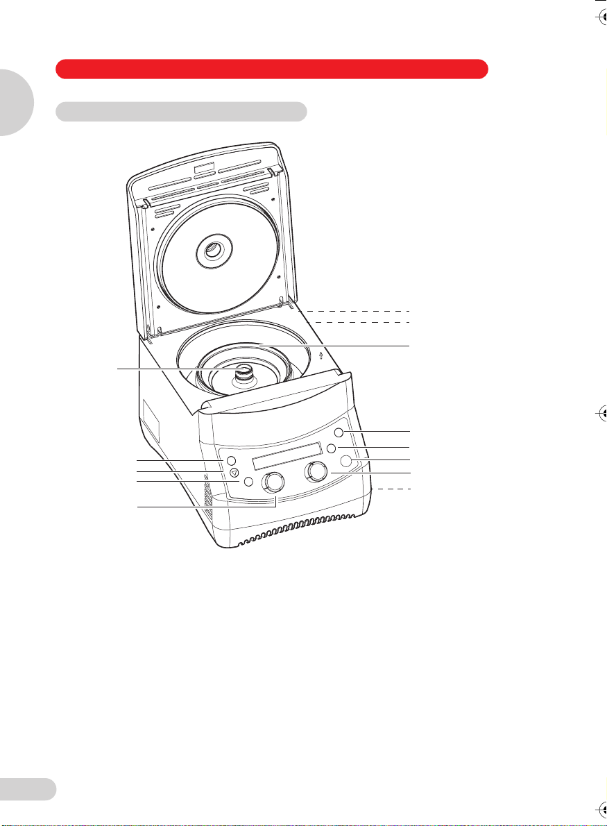
Figure 1 / Abbildung 1
Figure 1 / Abbildung 1
3
menu/enter
Arrow button
rpm/rcf
time
1
2
4
open
short
start/stop
speed
E
menu/enter
Arrow button
rpm/rcf
time
speed
open
short
start/stop
1
2
3
4
E
3
menu/enter button menu/enter-Taste
Arrow button Pfeiltaste
rpm/rcf button rpm/rcf-Taste
Time arrow buttons Zeitwahl-Pfeiltasten
Speed arrow buttons Geschwindigkeits-Pfeiltasten
Lid release button Deckelentriegelungs-Taste
Short run button Kurzzeitlauf-Taste
Start/stop button Start/Stop-Taste
Power plug Netzstecker
Power switch Netzschalter
Rotor nut Rotormutter
Rotor Rotor
Emergency lid release Notentriegelung
Page 4
Centrifuge 5424
Figure 2 / Abbildung 2
Figure 2 / Abbildung 2
3
menu/enter
Arrow button
rpm/rcf
time
1
2
4
open
short
start/stop
speed
E
menu/enter
Arrow button
rpm/rcf
time
speed
open
short
start/stop
1
2
3
4
E
4
menu/enter button menu/enter-Taste
Arrow button Pfeiltaste
rpm/rcf button rpm/rcf-Taste
Time knob Zeitwahl-Drehknopf
Speed selector knob Geschwindigkeits-Drehknopf
Lid release button Deckelentriegelungs-Taste
Short run button Kurzzeitlauf-Taste
Start/stop button Start/Stop-Taste
Power plug Netzstecker
Power switch Netzschalter
Rotor nut Rotormutter
Rotor Rotor
Emergency lid release Notentriegelung
Page 5

Table of contents
1 Introduction................................................................................................................28
1.1 Delivery package .........................................................................................................28
1.2 Installing the device .....................................................................................................28
2 Safety precautions and applicational limitations....................................................30
3 Operation....................................................................................................................33
3.1 Functional and operator control elements...................................................................33
3.2 Menu structure.............................................................................................................34
3.3 Fitting and removing the rotors ...................................................................................34
3.4 Loading the rotors .......................................................................................................34
3.5 Rotors ..........................................................................................................................34
3.6 Centrifugation with timer setting..................................................................................35
3.7 Adjusting centrifuging parameters during centrifugation ............................................35
3.8 Short spin centrifugation .............................................................................................36
3.9 Continuous operation ..................................................................................................36
3.10 rcf display and calculation...........................................................................................37
3.11 Setting startup and braking ramp................................................................................38
3.12 Run start ......................................................................................................................38
3.13 Permanent setting of parameters ................................................................................39
3.14 Activating and deactivating the loudspeaker ..............................................................39
3.15 Volume control.............................................................................................................40
3.16 Standby mode .............................................................................................................40
3.17 Opening the centrifuge in case of power failure..........................................................41
3.18 Fuses ...........................................................................................................................41
4 Maintenance and cleaning........................................................................................42
4.1 Device ..........................................................................................................................42
4.2 Rotors ..........................................................................................................................42
4.3 Glass breakage............................................................................................................43
4.4 Returning devices ........................................................................................................43
5 Troubleshooting ........................................................................................................44
6 Technical data............................................................................................................45
7 Ordering information .................................................................................................46
Table of contents
27
Page 6

The Centrifuge 5424 is a non-refrigerated bench-top centrifuge. It is intended for sample
preparation within the sphere of clinical diagnostics and in the routine, training and research
laboratory in hospitals, science and industry. The devices may only be operated by trained
specialist staff.
1
The various fixed-angle rotors and adapters enable a large number of tubes like micro test
tubes, PCR strips, Microtainers® and Spin Columns to be used. In the context of in vitro
diagnostics, the Centrifuge 5424 is designed among other things for chromosome analysis of
human cells by the FISH technique (Kievits et al. 1990).
Before using the centrifuge 5424 for the first time, please read the manual. The latest
version of the manual and the safety instructions in your language can be found on the
Internet at www.eppendorf.com.
Introduction
1 Centrifuge 5424
1 Rotor FA-45-24-11 incl. rotor lid (only for order no. 5424 000.410, 5424 000.010,
1 power cable
1 manual
1 rotor key
1 Captain Eppi rotor key holder
1 set of fuses
1 Introduction
You will see this symbol on your centrifuge and at a number of points throughout this
manual. The texts it highlights are relevant to safety. Use the centrifuge only when you
have read these safety instructions.
1.1 Delivery package
5424 000.428, 5424 000.029, 022620428, 022620461, 022620401 and 022620444)
1.2 Installing the device
– To disconnect the power supply of the centrifuge from the power supply in the
event of a fault, an emergency switch must be provided away from the centrifuge,
preferably outside the room in which the centrifuge is located or next to the exit
from this room.
– Remove the transport safety device and keep it together with the centrifuge pack-
aging for possible use if the device is subsequently moved.
– Place the centrifuge on a solid, flat, non-resonant lab bench. Check beforehand
whether the lab bench is specified for the weight of the centrifuge.
– The surrounding area must be well-ventilated and protected against direct sunlight.
To ensure that ventilation of the device is not impaired, a minimum fundamental
clearance of at least 30 cm to the side and at least 15 cm to the back wall must be
maintained.
– During centrifugation, according to the recommendations set out in EN 61010-2-020,
a safety clearance of 30 cm must be maintained around the centrifuge within which
there are no objects which may be destroyed and so cause further damage.
– Please ascertain that the power supply and the power frequency are compatible
28
with the information given on the device ID plate.
Page 7

1 Introduction
– Now connect the centrifuge to the power supply and switch it on at the main power
switch (see inside cover page). The centrifuge is now ready for operation and the
display is active.
– Before starting for the first time, check whether the rotor and the rotor lid are
tightened in accordance with specification. To tighten the rotor, place the rotor
key supplied on the rotor nut and turn it clockwise until the rotor nut is firmly tightened up. The rotor lid is then tightened up.
1
Introduction
29
Page 8

2 Safety precautions and applicational limitations
For your personal safety, please be sure to comply with the following regulations
unconditionally.
– The centrifuge 5424 must only be used for the specified applications (see Section 1,
“Introduction”). It must not be operated in explosive atmospheres. Explosive, radioactive
2
Safety precautions and applicational limitations
or highly reactive substances must not be centrifuged.
– When being moved from the cool room to a normal lab environment, the centrifuge must
either run for half an hour in the cool room first to warm up, or it must warm up for at least
3 hours in the lab before being connected to the power supply system, in order to prevent
damage from condensation.
– The centrifuge must not be moved or knocked while in operation.
– Centrifuges which have not been properly installed or repaired may not be operated.
Repairs may only be carried out by Service personnel authorized by Eppendorf. Use only
original Eppendorf spare parts and rotors.
– When handling toxic liquids or pathogenic microorganisms of risk group II (see World Health
Organization: Laboratory Biosafety Manual) comply with the relevant national regulations.
Bioseals are a component of biosafety systems which are not capable, in isolation, of
ensuring that people and the environment are protected when pathogenic microorganisms
are being handled. When working with pathogenic microorganisms of a higher risk group,
more than one aerosol-tight bioseal must be provided for. If the named liquids are spilled in
the rotor or rotor chamber, the centrifuge must be thoroughly and professionally cleaned.
Before using any cleaning or decontamination method other than that set out in Section 4,
"Maintenance and cleaning", please consult Eppendorf to ensure the intended method will
not damage the device.
– Rotors and rotor lids must always be properly secured. The centrifuge may only be
operated with the rotor and rotor lid firmly tightened. To do this, before centrifugation,
place the rotor key supplied for tightening up the rotor on the rotor nut and turn it
clockwise until the rotor nut is firmly tightened up. The rotor lid is then screwed on
tightly (see Section 3.5 "Rotors" with regard to exceptions for rotors FA-45-24-11 and
FA-45-24-11-Special for centrifuging micro test tubes with closed tube lids).
If unusual noises occur when the centrifuge starts, the rotor or the rotor lid are not properly
secure. In this case, stop centrifugation immediately using start/stop.
– The rotor may only be loaded symmetrically. Opposing vessels should be of the same type
and be filled equally. On each rotor you will find information about maximum load (adapter,
tube and contents) per bore - this limit may not be exceeded.
– Rotors showing clear signs of corrosion or mechanical damage must not be used. Check
the accessories regularly.
30
Page 9

2 Safety precautions and applicational limitations
– Rotors are high-grade components which have to withstand extreme stresses and strains.
Aluminum rotors are surface-treated to provide them with a high level of protection from
corrosion by the most common laboratory chemicals, though this protection is not unlimited. Avoid damage from the use of aggressive chemicals such as strong and weak alkalis,
strong acids, solutions of mercury, copper and other heavy metal ions, chlorinated hydrocarbons, concentrated salt solutions and phenol. If the rotor is contaminated by aggressive
substances, clean it immediately with a neutral agent (e.g. Extran® neutral, RBS® neutral or
Teepol® 610 S). This applies to the rotor bores in particular.
Rotors labeled "coated" are particularly resistant to chemicals. However, even on these
rotors, this does not replace regular cleaning as described in Section 4 "Maintenance and
cleaning".
Protect the rotors from mechanical damage. Even minor scratches or cracks can result in
serious internal material damage.
– The material being centrifuged may not exceed a density of 1.2 g/ml at maximum speed.
– If the rotor is run for a lengthy period or more often with short centrifugation runs, the sam-
ple tubes will become hot.
– Keep within the load limits specified for the tubes by the tube manufacturer. Tubes may only
be centrifuged at the preselected g-force (rcf) if they are approved for this application by the
manufacturer.
– Before centrifugation, all the tubes should be subjected to a visual inspection for material
damage. Damaged tubes must not be centrifuged, as if tubes break, there may be further
damage to the centrifuge and its accessories in addition to loss of the sample.
– Tube lids must be sealed down tight before centrifuging. The lids of tubes which are not
sealed may rip off during centrifugation and damage the rotor lid and the centrifuge.
– When using organic solvents (e.g. phenol, chloroform), the durability of plastic tubes may be
impaired with the result that tubes may break during centrifugation.
– When closing the centrifuge lid, do not place your fingers between the lid and the centri-
fuge, otherwise they may be trapped.
– The transparent rotor covers made from polypropylene have a maximum useful life of 3
years. The date of manufacture is impressed on them in the form of a watch .
Rotors and rotor covers which have been damaged chemically or mechanically or
which have passed their maximum useful life must no longer be used.
12
1
11
2
10
3
1
9
4
8
0
5
7
6
2
Safety precautions and applicational limitations
Declaration concerning the ATEX directive (94/9/EC)
The present design and ambient conditions inside Eppendorf centrifuges mean that they are not
suitable for use in a potentially explosive atmosphere. The centrifuges must therefore only be
used in a safe environment such as the open environment of a ventilated laboratory or a fullyextracted fume hood. The use of substances which may contribute to a potentially explosive
atmosphere is not permitted. The final decision on the risks in connection with the use of such
substances is the responsibility of the user of the centrifuge.
31
Page 10

2 Safety precautions and applicational limitations
Transfer
If the device is passed on to someone else, please include the instruction manual.
Disposal
2
In case the product is to be disposed of, the relevant legal regulations are to be observed.
Information on the disposal of electrical and electronic devices in the European
Community
The disposal of electrical devices is regulated within the European Community by national
regulations based on EU Directive 2002/96/EC on waste electrical and electronic equipment
(WEEE).
According to these regulations, any devices supplied after 13.08.05 in the business-to-business
sphere, to which this product is assigned, may no longer be disposed of in municipal or
domestic waste. They are marked with the following symbol to indicate this.
As disposal regulations within the EU may vary from country to country, please contact
your supplier if necessary.
Safety precautions and applicational limitations
32
Page 11

3 Operation
3.1 Functional and operator control elements
See the frontal view (Figure 1 / 2) on the first inside cover page of this manual.
menu/enter Menu/enter button see Section 3.8
Arrow button see Section 3.8
rpm/rcf rpm/rcf button see Section 3.10
time Time knob/arrow buttons see Sections 3.6, 3.7 and 3.9
speed Speed selector knob/arrow
buttons
open Lid release button see Section 3.6
short Short run button see Section 3.8
start/stop Start/stop button see Section 3.6
1 Power plug see Section 3.6
2 Power switch see Section 3.6
3 Rotor nut see Section 3.3
4 Rotor see Sections 3.3 to 3.5
E Emergency lid release see Section 3.17
3.2 Menu structure
In the menu you can
– adjust the startup and braking ramp,
– activate and deactivate the loudspeaker,
– adjust run start,
– vary the speed of short run centrifugation,
– switch standby mode on and off,
– control volume and
– set permanent centrifugation parameters.
menu/enter activates the menu and confirms a selected menu item or adjusted setting.
the arrow button selects a menu item
The menu consists of two levels, M1 and M2. In the first menu level, you can select between the
various menu items. The symbols for the functions light up. In addition, the symbol for each
menu item selected flashes in the activated setting. In the second menu level, the setting for the
selected function can be amended. The relevant symbol always appears when the settings are
selected.
The last inside cover page shows the menu structure with reference to the relevant sections of
this manual.
see Sections 3.6 and 3.7
3
Operation
33
Page 12

3 Operation
3.3 Fitting and removing the rotors
Fit the rotor onto the motor shaft and tighten the rotor nut firmly by turning it clockwise
using the appropriate rotor key provided. Before each start, check that the rotor is firmly
3
tightened.
To release the rotor, turn the rotor nut anticlockwise using the rotor key.
Under no circumstances centrifuge with rotors which already have obvious traces of
corrosion or mechanical damage (see Section 2 "Safety precautions and applicational
limitations").
Operation
3.4 Loading the rotors
The rotors must only be loaded symmetrically. The adapters must be loaded only with
the specified tubes. Minimize differences in weight between the filled sample tubes taring with a scale is recommended. This will reduce wear on the drive and cut running
noise.
The maximum load per bore is indicated on each rotor.
3.5 Rotors
A maximum of 24 x 1.5/2.0 ml micro test tubes can be centrifuged in rotors FA-45-24-11 and
FA-45-24-11-Special. With the appropriate adapters, it is also possible to load it with 0.2 ml
PCR tubes, 0.4 ml micro test tubes, 0.5 ml micro test tubes and 0.6 ml Microtainers
possible to load the rotor with 24 Spin Columns. However, the rotor F-45-18-11-Kit is recommended for centrifuging Spin Columns. The maximum speed of rotors FA-45-24-11 and
FA-45-24-11-Special is 14,680 rpm (120 V: 15,000 rpm) and the maximum g-force (rcf)
20,238 x g (120 V: 21,130 x g). The maximum load (adapter, tube and contents) per bore for the
rotors is 3.75 g.
Rotors FA-45-24-11 and FA-45-24-11-Special can be operated both with and without
a rotor lid. Without a rotor lid, the rotors are not aerosol-tight and are slightly noisier.
Particular attention should be paid to the fact that tube lids are closed in accordance
with specification before centrifugation. Aerosol-tight centrifugation can only be carried
out with the rotor lid in place. Spin Columns must always be centrifuged with the
rotor lid. The rotor lid is not required during standard operation.
With the rotor F-45-18-11-Kit, up to 18 Spin Columns can be centrifuged at a maximum of
14,680 rpm (120 V: 15,000 rpm) or 17,347 x g (120 V: 18,111 x g). This rotor is characterized by
a particularly high edge so that all standard Spin Columns fit under the rotor lid. But it is also
possible to load the rotor with 1.5/2.0 ml micro test tubes, and using the appropriate adapters,
with 0.2 ml PCR tubes, 0.4 ml micro test tubes, 0.5 ml micro test tubes and 0.6 ml Microtainers®. The maximum load (adapter, tube and contents) per bore for this rotor is 3.75 g.
Rotor F-45-18-11-Kit may only be centrifuged with the rotor lid tightened in
accordance with specification.
®
. It is also
34
Page 13

3 Operation
With rotor F-45-32-5-PCR, up to 32 PCR tubes (0.2 ml) or four 5x or 8x rows of 0.2 ml PCR
tubes can be centrifuged at maximum 14,680 rpm (120 V: 15,000 rpm) or 17,829 x g (120 V:
18,615 x g). Maximum load (tubes and contents) per 8x row with this rotor is 3.5 g.
Rotor F-45-32-5-PCR may only be centrifuged with the rotor lid tightened in
accordance with specification.
When loading rotors, make sure that the micro test tubes are inserted in the rotor bores
opposite one another in pairs. To ensure that the rotor is symmetrically loaded,
opposing tubes must contain the same filling volume.
3.6 Centrifugation with timer setting
Switch on the centrifuge with the power switch if necessary and open the lid using the open
button. The specified values of the last run are displayed. Load the rotor symmetrically, fit the
rotor lid and close the centrifuge lid.
time adjusts the run time up to 10 min. in 0.5 min. increments, then in 1 min.
increments up to 09:59 h.
speed adjusts the speed in increments of 50 rpm or the g-force (rcf) in increments of
50 x g.
start/stop starts centrifugation. The symbol ■ flashes while the rotor is running.
During centrifugation, the remaining run time is displayed in minutes. The last minute is counted
down in seconds. In addition, the speed of the rotor/relevant g-force (rcf) is displayed. The timer
setting, speed and rpm/rcf display can be adjusted during centrifugation. The menu, the open
and the short buttons are blocked during centrifugation.
start/stop if the button is pressed again, centrifugation is stopped before expiry of the set
run time.
After expiry of the set run time, the centrifuge will otherwise stop automatically. During braking,
the timer flashes and shows the spin time which has elapsed. When the rotor has come to a
standstill, a signal tone is heard and the centrifuge lid opens automatically. The display then
shows the symbol .
3
Operation
3.7 Adjusting centrifuging parameters during centrifugation
The timer setting and rotation speed can be changed during centrifugation using the two knobs
or the arrow buttons. If these parameters are adjusted, the display begins flashing. The new
centrifuging parameters are accepted after a short time.
The time which has elapsed up to this point is offset against the new actual value. In order that
centrifugation cannot be stopped by changing the timer setting, the shortest time which can be
set is the time which has already elapsed plus 2 minutes. Parameters cannot be adjusted during
the braking process.
35
Page 14

3
Operation
3 Operation
3.8 Short spin centrifugation
Switch on the centrifuge with the power switch if necessary and open the lid using the open
button. The specified values of the last run are displayed. Load the rotor symmetrically, fit the
rotor lid and close the centrifuge lid.
short starts a short run at the specified speed. The short button must be kept
depressed throughout the entire short run. The symbol ■ flashes while the rotor is
running. Time is counted upwards in seconds. Centrifugation is stopped by
releasing the short button during the braking process, centrifugation can be restarted twice by pressing the short button again.
The timer flashes and shows the spin time which has elapsed during braking. When the rotor
has come to a standstill, the centrifuge lid opens automatically. The display then shows the
symbol .
During a short run, all other buttons and knobs are blocked.
Specified speed is set via the menu:
menu/enter activates the menu.
select the item SHORT and confirm with
menu/enter.
in the second menu level, select the item MAX in order to centrifuge at maximum
speed/g-force. To perform short-run centrifugation at the currently-set speed/
g-force, select the item SET with the arrow button.
menu/enter confirms the set speed and you automatically return to the item BACK in the first
menu level. Press the key again to exit the menu.
If the specified speed is not to be changed after all, it is possible to exit the second menu level
by selecting the BACK menu item and then confirming with the menu/enter button.
3.9 Continuous operation
Switch on the centrifuge with the power switch if necessary and open the lid using the open
button. The specified values of the last run are displayed. Load the rotor symmetrically, fit the
rotor lid and close the centrifuge lid.
time the continuous function is set using the time selection knob/arrow buttons to
above 09:59 h or below 30 sec. The timer shows "oo" to indicate continuous running. Time is counted upwards in 30-second increments.
speed adjusts the speed in increments of 50 rpm or the g-force (rcf) in increments of
50 x g.
start/stop starts centrifugation. The symbol ■ flashes while the rotor is running.
start/stop if the button is pressed again, centrifugation will stop.
During braking, the timer flashes and shows the spin time which has elapsed. When the rotor
has come to a standstill, a signal tone is heard and the centrifuge lid opens automatically. The
display then shows the symbol .
36
Page 15

3 Operation
3.10 rcf display and calculation
rpm/rcf Pressing the button toggles the display from rpm (1/min) to rcf and vice versa.
Please note that the g-force (rcf) shown when toggling the display is standardized to rotor
FA-45-24-11/ FA-45-24-11-Special without adapter. At the maximum speed in each case you
can achieve the following maximum g-force (rcf) in the various rotors with the different adapters:
Rotor Adapter
FA-45-24-11,
FA-45-24-11Special
F-45-18-11-Kit without adapter 7,2 17.347 18.111
F-45-32-5-PCR 7,4 17.829 18.615
To calculate the g-force (rcf) for a specific adapter you can apply the following formula according to DIN 58 970:
rcf = 1.118 • 10-5 • n2 • r
n: speed in rpm
r
: max. centrifugal radius in cm
max
Example: in rotor FA-45-24-11, the 0.5 ml adapter has a maximum radius of 7.3 cm.
At 7,000 rpm, a maximum g-force (rcf) of 4,000 x g is achieved.
without adapter 8,4 20.238 21.130
0.2 ml 6,3 15.179 15.848
0.4 ml 8,4 20.238 21.130
0.5 ml 7,3 17.588 18.363
0.6 ml 8,4 20.238 21.130
0.2 ml 5,1 12.288 12.829
0.4 ml 7,2 17.347 18.111
0.5 ml 6,1 14.697 15.345
0.6 ml 7,2 17.347 18.111
max
Max. centrifugal
radius r
max
Max. g-force (rcf)
[cm]
(230 V / 100 V)
Max. g-force (rcf)
(120V)
3
Operation
37
Page 16

3
Operation
3 Operation
3.11 Setting startup and braking ramp
When setting the startup and braking ramp, you can select between two levels. Selection is
made using the menu:
menu/enter activates the menu.
select the item SOFT and confirm with
menu/enter.
in the second menu level, select the item ON for the rotor to start up and brake
more slowly and the item OFF for it to start up and brake more quickly.
menu/enter confirms the amended startup and braking ramp and you automatically return to
the item BACK in the first menu level. Press the key again to exit the menu.
If the startup and braking ramp is not to be changed after all, it is possible to exit the second
menu level by selecting the BACK menu item and then confirming with the menu/enter button.
If the slower startup and braking ramp is switched on, the symbol appears in the display.
3.12 Run start
For centrifugation, time can be counted either immediately from the start or not until attainment
of the preset speed or g-force (rcf). This is specified via the menu:
menu/enter activates the menu.
select the item ATSET and confirm with
menu/enter.
In the second menu level select the item ON for time to the counted only once the
set speed/g-force (rcf) has been reached. Select the item OFF if time is to be
counted from the start of centrifugation.
menu/enter confirms the selected run start and you automatically return to the item BACK in
the first menu level. Press the key again to exit the menu.
If the setting for run start is not to be changed after all, it is possible to exit the second menu
level by selecting the BACK menu item and then confirming with the menu/enter button.
The selected setting is shown in the display. If time is counted from the start, the symbol
appears. If time is only counted from when the specified speed/g-force (rcf) is reached, this is
symbolized by .
soft
38
Page 17

3 Operation
3.13 Permanent setting of parameters
The selected centrifugation parameters can be permanently set via the menu so that neither
time or rotation speed/g-force (rcf) can be altered using the relevant knobs/arrow buttons:
menu/enter activates the menu.
select the item LOCK and confirm with
menu/enter.
In the second menu level, select the item ON if centrifugation parameters are to be
made permanent. To enable centrifugation parameters to be set freely, select the
item OFF using the arrow button.
menu/enter confirms the permanent setting of parameters and you automatically return to the
item BACK in the first menu level. Press the key again to exit the menu.
If the permanent setting of parameters is not to be changed after all, it is possible to exit the
second menu level by selecting the BACK menu item and then confirming with the menu/enter
button.
The selected setting is shown in the display. Once the centrifugation parameters are locked, the
display shows the symbol of a . If the set parameters can be adjusted, this is symbolized by
an .
If the parameters have been permanently set and these are to be changed using the knobs/
arrow buttons, SAFE appears in the display.
3.14 Activating and deactivating the loudspeaker
3
Operation
The loudspeaker is activated and deactivated via the menu:
menu/enter activates the menu.
select the item ALARM and confirm with
menu/enter.
In the second menu level, select the item ON to activate the loudspeaker.
The loudspeaker can be deactivated via the OFF item.
menu/enter confirms that the loudspeaker has been activated/deactivated and you automati-
cally return to the item BACK in the first menu level. Press the key again to exit the
menu.
If the setting for the loudspeaker is not to be changed after all, it is possible to exit the second
menu level by selecting the BACK menu item and then confirming with the menu/enter button.
When the loudspeaker is activated, the symbol appears in the display.
39
Page 18

3
Operation
3 Operation
3.15 Volume control
The volume of the loudspeaker is controlled in the menu. The loudspeaker needs to be activated for you to hear the change in volume (see Section 3.14 "Activating and deactivating the
loudspeaker"):
menu/enter activates the menu.
select the item VOL and confirm with
menu/enter.
In the second menu level, select the item VOL1. A bleep is heard. To increase the
volume of this sound further, use the arrow button to select the other items VOL2
to VOL5. For every change, a signal at the new volume is heard, becoming louder
each time.
menu/enter confirms the selected volume of the loudspeaker and you automatically return to
the item BACK in the first menu level. Press the key again to exit the menu.
If the volume is not to be changed after all, it is possible to exit the second menu level by selecting the BACK menu item and then confirming with the menu/enter button.
3.16 Standby mode
If the centrifuge has not been used for 15 min., it switches to standby mode. The “EP” logo then
appears in the display. When a button (or knob) is used or the centrifuge lid is closed, the centrifuge is reactivated and ready for operation.
Standby mode can be switched on and off via the menu:
menu/enter activates the menu.
select the item SLEEP and confirm with
menu/enter.
In the second menu level, select the item ON to switch on Standby mode.
Standby mode can be switched off via the OFF item.
menu/enter confirms that Standby mode has been switched on/off and you automatically
return to the item BACK in the first menu level. Press the key again to exit the
menu.
If standby mode is not to be changed after all, it is possible to exit the second menu level by
selecting the BACK menu item and then confirming with the menu/enter button.
40
Page 19

3 Operation
3.17 Opening the centrifuge in case of power failure
If the lid release does not function following a power failure, the emergency lid release
can be operated by hand.
To do so, first unplug the power plug. Before activating the emergency release, also
ensure that the rotor has come to a standstill. Check by looking through the window in
the centrifuge lid. It can take up to 6 minutes for the rotor to come to a standstill.
The emergency release is located on the right-hand side of the centrifuge (see “E” in
Figure 1 / 2, first inside cover page).
After a visual check that the rotor has come to a standstill, first remove the plastic cap.
The rotor key supplied then has to be inserted in the nut underneath the cap and turned
anticlockwise. This releases the lid and allows it to be opened.
The rotor key must then be removed immediately and the plastic cap put back on.
3.18 Device fuses
The fuse box is located under the power plug. To replace the fuses, unplug the power plug and
pull the fuse box out towards the rear. The two fuses can then be replaced (see Ordering
information).
3
Operation
41
Page 20

4 Maintenance and cleaning
4.1 Device
The outer surfaces of the centrifuge and the rotor chamber should be cleaned regularly with a
neutral agent (e.g. Extran
4
poses and to prevent adhering impurities causing corrosion.
If material hazardous to health or aggressive material contaminate the device, the owner is
responsible for appropriate cleaning and decontamination.
Before cleaning, unplug the power plug with the lid open, unscrew the rotor using the rotor key
supplied and clean it separately. Use only neutral agents for cleaning (e.g. Extran
®
RBS
neutral, Teepol® 610 S). Bacillol® AF, Meliseptol® und Perform® are recommended for
cleaning and disinfecting the outer surface of the centrifuge and the rotor chamber. Do not allow
any liquid to get into the gap at the motor shaft outlet. For this reason, the rotor chamber should
be cleaned only with a damp cloth.
The outer surface of the centrifuge and the rotor chamber have been tested for resistance to the
cleaning agents and disinfectants mentioned. However, this does not guarantee that the device
is disinfected following application of one of the methods mentioned. You should also consult
your laboratory safety officer with regard to a suitable method of cleaning and disinfecting.
Before any cleaning or disinfecting method other than that recommended by the manufacturer
Maintenance and cleaning
is used, please check with Eppendorf that the intended method will not damage the device or
its accessories. In order to ensure long-term, reliable work with your centrifuge, please note that
aggressive chemicals may damage the rotor and the chamber. Check your device once a month
for corrosion and damage.
The rubber seals in the rotor chamber should be rinsed off thoroughly with water and lubricated
with glycerin or talc after every clean to prevent them becoming brittle.
4.2 Rotors
Rotors need cleaning regularly to prevent residues of the material being centrifuged from
changing their properties. Check the rotors for residues and corrosion at least once a month.
This applies to the rotor bores in particular. Please look after your rotor regularly; this will protect
it and increase its service life.
For thorough cleaning, the rotor is unscrewed using the rotor key supplied and cleaned using a
neutral agent (e.g. Extran
®
Perform
rotor bores are also brushed out with a bottle brush. The rotor and bores are then rinsed out
thoroughly and placed on a cloth with the bores facing downwards to dry. The rotor is then put
back in and the rotor nut tightened up.
The rotors have been tested for resistance to the cleaning agents and disinfectants mentioned.
However, this does not guarantee that the device is disinfected following application of one of
the methods mentioned. You should also consult your laboratory safety officer with regard to a
suitable method of cleaning and disinfecting. However, before any cleaning or disinfecting
method other than that recommended by the manufacturer is used, please check with Eppendorf that the intended method will not damage the rotors or their accessories. In order to ensure
long-term, reliable work with your centrifuge, please note that aggressive chemicals may damage the rotor.
are recommended for cleaning and disinfecting the rotor and the rotor bores. The
®
neutral, RBS® neutral or Teepol® 610 S). This is for hygiene pur-
®
neutral,
®
neutral, RBS® neutral, Teepol® 610 S). Bacillol® AF, Meliseptol® und
42
Page 21

4 Maintenance and cleaning
All the rotors, rotor lids and adapters can be autoclaved (121 ˚C, 20 min.). The lids of aerosoltight rotors FA-45-24-11 and FA-45-24-11-Special should be replaced after no more than
50 autoclaving operations.
On the aerosol-tight rotors, the rotor lids should be replaced if the sealing rings on the lid thread
and in the lid groove become worn. Regular care of the sealing rings is required to protect the
rotors. Check that the seals are undamaged before use.
Aerosol-tight rotors may not be stored with lids done up tightly!
4.3 Glass breakage
When centrifuging glass tubes, be aware that as speed/rcf increases, so does the risk of glass
breaking. Please observe manufacturers’ information about maximum loading of centrifuge
tubes.
In case of glass breakage, carefully remove all splinters and all ground glass from the rotor, the
adapters and the rotor chamber. You may need to replace adapters in order to prevent further
damage.
Otherwise fine glass splinters will scratch the surface of the rotors, reducing their resistance to
chemicals. Air vortices will result in very fine black abraded metal in the rotor chamber; in addition to damaging the rotor chamber, rotor and adapters, this material will also cause samples to
become contaminated.
Check the rotor bores regularly for residues or damage.
4.4 Returning devices
4
Maintenance and cleaning
When returning centrifuges, ensure that these devices are fully decontaminated and do not
present any kind of health risk to our service staff.
For further information and a blank of the decontamination confirmation, please visit
www.eppendorf.com. Do also consult your laboratory safety officer about a suitable decontamination method.
Please fill in the decontamination confirmation and enclose it with the device if it is to be
returned to Eppendorf.
43
Page 22

5 Troubleshooting guide
If the suggested rectification measures repeatedly fail, contact Eppendorf.
Error / Display Cause Remedy
5
Troubleshooting guide
No display No power Check power connection
Lid cannot be opened Power failure See above, activate emergency lid
Centrifuge will not start Lid not closed Press lid shut
Centrifuge shakes when
starting up
Centrifuge brakes during a
short run although the
short button is still
depressed
LID ERROR Lid cannot be locked Close lid again and start
INT Power interruption
NO RPM Error in speed
Err 6 Drive error Repeat run, if error recurs => Service
Err 7 Overspeed or major
Err 8 Rotor loose, drive error Tighten up rotor, repeat run, if error
Err 11 Power interruption
Err 9, 10, 12 - 17 Electronics error Repeat run, if error recurs => Service
Power failure Check power fuses of device and
Rotor still running Wait for rotor to stop
Rotor unevenly loaded Stop centrifugation and load evenly
Button was released
briefly more than 2x
(drive protection
function)
Lid cannot be unlocked Switch device off and back on, press
Lid cannot be unlocked
during a run
during a run
measuring system
control deviation
during a run
laboratory
release
Do not release button during a short
run
the open button, if error recurs:
switch off device, activate emergency
lid release, if error recurs => Service
Wait for centrifuge to come to a
standstill, repeat run, if error recurs
=> Service
Check power plug
Leave device switched on until the
error message disappears (10 s or
6 min.), repeat run, if error recurs =>
Service
Check rotor properly tightened,
repeat run
recurs => Service
Check power plug, repeat run
44
Page 23

6 Technical data
Mains power connection: 230 V / 50 – 60 Hz
120 V / 50 - 60 Hz
100 V / 50 - 60 Hz
Power output 250 W
Max. speed 100 to 14,680 rpm (230 V / 100 V)
100 to 15,000 rpm (120 V)
Max. relative centrifugal force (rcf) 20,238 x g (230 V / 100 V)
21,130 x g (120 V)
Max. load 24 x 2.0 ml micro test tubes
Max. kinetic energy 7500 Nm
Permissible density of material to be centrifuged 1.2 g/ml
Ambient temperature 2 - 40 ˚C
Relative humidity 10 - 75 %
Setup height max. 2000 m above NSL
Dimensions Width: 236 mm
Depth: 320 mm
Height: 227 mm
Weight excluding rotor: 13.4 kg
Startup time (230 V) 15 s
Deceleration time (230 V) 16 s
Startup time (120 V) 15 s
Deceleration time (120 V) 18 s
Startup time (100 V) 20 s
Deceleration time (100 V) 16 s
Fuses 3.15 AT (230 V)
6.3 AT (120 V / 100 V)
Noise level < 56 dB (A)
Overvoltage category II
Degree of contamination: 2
6
Technical data
Technical specifications subject to change!
45
Page 24

7 Ordering information
Centrifuge 5424
7
with knobs, without rotor
230 V / 50 - 60 Hz 5424 000.614 022620436
Centrifuge 5424
with keypad, without rotor
230 V / 50 - 60 Hz 5424 000.215 022620452
Centrifuge 5424
with knobs, with rotor FA-45-24-11
incl. rotor lid, 230 V / 50 - 60 Hz 5424 000.410 022620428
Centrifuge 5424
with keypad, with rotor FA-45-24-11
incl. rotor lid, 230 V / 50 - 60 Hz 5424 000.010 022620461
Ordering information
Centrifuge 5424
with knobs, without rotor
120 V / 50 - 60 Hz 5424 000.622 022620487
Centrifuge 5424
with keypad, without rotor
120 V / 50 - 60 Hz 5424 000.223 022620498
Centrifuge 5424
with knobs, with rotor FA-45-24-11
incl. rotor lid, 120 V / 50 - 60 Hz 5424 000.428 022620401
Centrifuge 5424
with keypad, with rotor FA-45-24-11
incl. rotor lid, 120 V / 50 - 60 Hz 5424 000.029 022620444
Fixed-angle rotors and rotor lids
Fixed-angle rotor FA-45-24-11
with rotor lid, aluminum, aerosol-tight,
angle 45˚, 24 places, max. diameter 11 mm,
designed for 1.5/2.0 ml micro test tubes 5424 702.007 022653008
Spare lid (aluminum) for rotor FA-45-24-11,
aerosol-tight 5424 703.003 022653024
Fixed-angle rotor FA-45-24-11-Special
with rotor lid, aluminum, aerosol-tight, coated
angle 45˚, 24 places, max. diameter 11 mm,
designed for 1.5/2.0 ml micro test tubes 5424 700.004 022653041
Spare lid (aluminum) for rotor
FA-45-24-11-Special, aerosol-tight, coated 5424 701.000 022653067
Order no. Order no.
International North America
46
Page 25

7 Ordering information
Order no. Order no.
International North America
Fixed-angle rotor F-45-18-11-Kit
with rotor lid, aluminum,
angle 45˚, 18 places, max. diameter 11 mm,
designed for 1.5/2.0 ml micro test tubes 5424 706.002 022653083
Spare lid (polypropylene) for rotor F-45-18-11-Kit 5424 707.009 022653105
Fixed-angle rotor F-45-32-5-PCR
with rotor lid, aluminum,
angle 45˚, 32 places, max. diameter 5 mm,
designed for 0.2 ml PCR tubes 5424 704.000 022653121
Spare lid (aluminum) for rotor F-45-32-5-PCR 5424 708.005 022653148
Accessories
Adapter for 0.2 ml PCR tubes,
for FA-45-24-11, FA-45-24-11-Special
and F-45-24-11-Kit, per 6 pcs 5425 715.005 022636260
Adapter for 0.4 ml micro test tubes,
for FA-45-18-11, FA-45-18-11-Special
and F-45-24-11-Kit, per 6 pcs 5425 717.008 022636243
Adapter for 0.5 ml micro test tubes
and 0.6 ml Microtainers
for FA-45-18-11, FA-45-18-11-Special
and F-45-24-11-Kit, per 6 pcs 5425 716.001 022636227
Rotor key 5416 301.001 022634305
Captain Eppi, rotor key holder, 1 pc 5703 350.102 022639609
Set of fuses 2 x 3.15 AT (230 V) 5424 852.122 950004266
®
,
2 x 6.3 AT (120 V / 100 V) 5424 852.130 950004240
7
Ordering information
Rotor code
All Eppendorf rotors are designated according to a simple, logical system which describes the
technical specifications as a uniform series of numbers and letters e.g.:
Fixed-angle Angle of
rotor
adapter bore
Ø Tube/
Adapter Swing-bucket rotor
Ø tube/adapter
bore
F A 45 30 11 A 4 81
Aerosol-tight
version
Max. no. tubes/
adapters
Max. no tubes/
adapters
47
Page 26

7 Ordering information
Important
Use only the original accessories we recommend. The functioning and safety of centrifuges may
be impaired if you use spares or disposables other than those we recommend! Any warranty
and liability for losses thus caused shall be excluded.
7
Bacillol® AF Registered trade mark of Bode Chemie GmbH & Co., Hamburg, Germany
®
Extran
neutral Registered trade mark of Merck KgaA, Darmstadt, Germany
Meliseptol
Microtainer
Perform
RBS
Teepol
Ordering information
®
®
®
®
neutral Registered trade mark of Carl Roth GmbH + Co. KG, Karlsruhe, Germany
®
610 S Registered trade mark of Sigma-Aldrich Corp., St. Louis, USA
Registered trade mark of B. Braun Melsungen AG, Melsungen, Germany
Registered trade mark of Becton Dickinson, Franklin Lakes, USA
Registered trade mark of Schülke & Mayr GmbH, Norderstedt, Germany
48
Page 27

Page 28

Page 29

Page 30

Menu structure / Menüstruktur
M1 M2
BACK
SOFT BACK
ON
OFF
ALARM BACK
ON
OFF
ATSET
SHORT
SLEEP
LOCK
VOL
BACK
ON
OFF
BACK
MAX
SHORT
BACK
ON
OFF
BACK
ON
OFF
BACK
VOL1
VOL2
VOL3
VOL4
VOL5
SOFT
see Section 3.11 /
siehe Kapitel 3.11
see Section 3.14 /
siehe Kapitel 3.14
see Section 3.12 /
siehe Kapitel 3.12
see Section 3.8 /
siehe Kapitel 3.8
see Section 3.16 /
siehe Kapitel 3.16
see Section 3.13 /
siehe Kapitel 3.13
see Section 3.15 /
siehe Kapitel 3.15
132
Page 31

Eppendorf Offices
SPAIN
SWITZERLAND
UNITED KINGDOM
USA
OTHER COUNTRIES
AUSTRALIA / NEW ZEALAND
Eppendorf South Pacific Pty. Ltd.
Tel. +61 2 98 89 50 00
Fax +61 2 98 89 51 11
E-Mail: Info@eppendorf.com.au
Internet: www.eppendorf.com.au
AUSTRIA
Eppendorf Austria
Tel. +43 1 2901756-0
Fax +43 1 2901756-20
E-Mail: office@eppendorf.at
Internet: www.eppendorf.at
BRAZIL
Eppendorf do Brasil Ltda.
Tel. +55 11 3095 9344
Fax +55 11 3095 9340
E-Mail:
eppendorf@eppendorf.com.br
Internet: www.eppendorf.com.br
CANADA
Eppendorf Canada Ltd.
Tel. +1 905 826 5525
Fax +1 905 826 5424
E-Mail: canada@eppendorf.com
Internet: www.eppendorfna.com
GERMANY
Eppendorf Vertrieb
Deutschland GmbH
Tel. +49 2232 418-0
Fax +49 2232 418-155
E-Mail: vertrieb@eppendorf.de
Internet: www.eppendorf.de
INDIA
Eppendorf India Limited
Tel. +91 44 42 11 13 14
Fax +91 44 42 18 74 05
E-Mail: info@eppendorf.co.in
Internet: www.eppendorf.co.in
ITALY
Eppendorf s.r.l.
Tel. +390 2 55 404 1
Fax +390 2 58 013 438
E-Mail: eppendorf@eppendorf.it
Internet: www.eppendorf.it
JAPAN
Eppendorf Co. Ltd.
Tel. +81 3 5825 2363
Fax +81 3 5825 2365
E-Mail: info@eppendorf.jp
Internet: www.eppendorf.jp
Eppendorf Ibérica S.L.U.
Tel. +34 91 651 76 94
Fax +34 91 651 81 44
E-Mail: iberica@eppendorf.es
Internet: www.eppendorf.es
Vaudaux-Eppendorf AG
Tel. +41 61 482 1414
Fax +41 61 482 1419
E-Mail: vaudaux@vaudaux.ch
Internet: www.eppendorf.ch
Eppendorf UK Limited
Tel. +44 1223 200 440
Fax +44 1223 200 441
E-Mail: sales@eppendorf.co.uk
Internet: www.eppendorf.co.uk
Eppendorf North America
Tel. +1 516 334 7500
Fax +1 516 334 7506
E-Mail: info@eppendorf.com
Internet: www.eppendorfna.com
CHINA
Eppendorf China Ltd.
Tel. +86 21 68760880
Fax +86 21 50815371
E-Mail: market.info@eppendorf.cn
Internet: www.eppendorf.cn
FRANCE
EPPENDORF FRANCE S.A.R.L.
Tel. +33 1 30 15 67 40
Fax +33 1 30 15 67 45
E-Mail: eppendorf@eppendorf.fr
Internet: www.eppendorf.fr
NORDIC
Eppendorf Nordic Aps
Tel. +45 70 22 29 70
Fax +45 45 76 73 70
E-Mail: nordic@eppendorf.dk
Internet: www.eppendorf.dk
SOUTH & SOUTHEAST ASIA
Eppendorf Asia Pacific Sdn. Bhd.
Tel. +60 3 8023 2769
Fax +60 3 8023 3720
E-Mail:
asiapacifichq@eppendorf.com.my
Internet: www.eppendorf.com.my
Internet:
www.eppendorf.com/worldwide
Page 32

is a registered trademark.
®
In touch with life
Your local distributor: www.eppendorf.com/worldwide
Eppendorf AG · 22331 Hamburg · Germany · Tel: +49 40 538 01-0 · Fax: +49 40 538 01-556
E-Mail: eppendorf@eppendorf.com
Eppendorf North America, Inc. · One Cantiague Road · P.O. Box 1019 · Westbury, N.Y. 11590-0207 · USA
Tel: +1 516 334 7500 · Toll free phone: +1 800 645 3050 · Fax: +1 516 334 7506 · E-Mail: info@eppendorf.com
Application Support
Europe, International: Tel: +49 1803 666 789 · E-Mail: support@eppendorf.com
North America: Tel: +1 800 645 3050 ext. 2258 · E-Mail: support_na@eppendorf.com
Asia, Pacific: Tel: +60 3 8023 6869 · E-Mail: support_asiapacific@eppendorf.com
eppendorf
B 5424 900.011-04/0408 · Printed in Germany
 Loading...