


Betriebsanleitung
S/W und Farb-Video Quad Splitter Modellreihe: VCQ-6057, VBQ-6045
Operating Instructions
B/W and Colour Video Quad Splitter
Model Series: VCQ-6057, VBQ-6045
Mode d’emploi
Quadravision noir/blanc et couleur Série: VCQ-6057, VBQ-6045
Instrucciones de manejo
Quad Splitter Video en B/N en color Series de modelos: VCQ-6057, VBQ-6045
Inhaltsverzeichnis |
Contents |
1. |
Sicherheitshinweise / Pflege........................................................................ |
3 |
|
2. |
Mitgeliefertes Zubehör................................................................................. |
3 |
|
3. |
Technische Merkmale.................................................................................. |
4 |
|
4. |
Lage und Funktion der Bedienelemente....................................................... |
4 |
|
5. |
Installation................................................................................................... |
7 |
|
|
5.1 |
Grundsätzliches Verkabelungsschema mit Alarm Ein-/Ausgang ............ |
7 |
|
5.2 |
VCR-Wiedergabe.................................................................................. |
8 |
|
5.3 |
Videorekorder-Anschluss für Aufzeichnungsund Start/Stop-Betrieb.... |
8 |
|
5.4 |
Montage der Einschub – Winkelsets .................................................... |
9 |
|
5.5 |
Fernsteuerungs - Anschluss................................................................ |
10 |
6. |
Bedienung................................................................................................. |
10 |
|
|
6.1 |
Bildschirm-Menü................................................................................ |
10 |
|
6.2 |
Quad-Darstellungs-Modus.................................................................. |
13 |
|
6.3 |
Vollbild - Darstellung.......................................................................... |
13 |
|
6.4 |
Standbild-Darstellung der Kamerabilder (FREEZE)............................... |
13 |
|
6.5 |
Alarm Einstellungen............................................................................ |
14 |
|
6.6 |
Sequenzieller Umlauf.......................................................................... |
14 |
|
6.7 |
VCR-Betrieb........................................................................................ |
15 |
7. |
Fernbedienbetrieb...................................................................................... |
15 |
|
|
7.1 |
Belegung der 9-pol. D-Sub-Buchse (Remote/RS-232) ........................ |
15 |
|
7.2 |
ASCII Steuercodes.............................................................................. |
16 |
8. |
Technische Daten....................................................................................... |
17 |
|
Anhang |
............................................................................................................. |
35 |
|
1. |
Safety Instructions / Maintenance................................................................ |
3 |
|
2. |
Supplied Accessories................................................................................... |
3 |
|
3. |
Features....................................................................................................... |
4 |
|
4. |
Operating Control and their Functions.......................................................... |
4 |
|
5. |
Installation Notes......................................................................................... |
7 |
|
|
5.1 |
Basic System Connection With Alarm Inputs and Output....................... |
7 |
|
5.2 |
VCR Connection for Zoom on Playback Operation.................................. |
8 |
|
5.3 |
VCR Connection for Tape Recording Start and Stop Control................... |
8 |
|
5.4 |
Use of Rack Mount Kit.......................................................................... |
9 |
|
5.5 |
Remote Control Connection................................................................ |
10 |
6. |
Operating................................................................................................... |
10 |
|
|
6.1 |
The Setup Menu ................................................................................ |
10 |
|
6.2 |
The Quad Display Mode...................................................................... |
13 |
|
6.3 |
The Full Screen Display Mode............................................................. |
13 |
|
6.4 |
The still frame display mode (FREEZE)................................................ |
13 |
|
6.5 |
Alarm Operations................................................................................ |
14 |
|
6.6 |
The Auto-Sequence Mode................................................................... |
14 |
|
6.7 |
VCR Operations................................................................................... |
15 |
7. |
Remote Control Operations........................................................................ |
15 |
|
|
7.1 |
Pin Assignment of the 9 pin D-Sub Connector..................................... |
15 |
|
7.2 |
ASCII Command codes........................................................................ |
16 |
8. |
Technical Data........................................................................................... |
18 |
|
Annex................................................................................................................ |
|
35 |
|
Sommaire |
Contenido |
1. |
Consignes de sécurité / Maintenance......................................................... |
19 |
|
2. |
Accessoires faisant partie de la fourniture.................................................. |
20 |
|
3. |
Caractéristiques techniques....................................................................... |
20 |
|
4. |
Position et fonctions des éléments de commande...................................... |
20 |
|
5. |
Installation................................................................................................. |
23 |
|
|
5.1 |
Schéma de principe du câblage avec entrée/sortie d’alarme............... |
23 |
|
5.2 |
Raccord magnétoscope...................................................................... |
24 |
|
5.3 |
Raccordement du magnétoscope pour les modes |
|
|
|
enregistrement et Start/Stop............................................................... |
24 |
|
5.4 |
Montage du rack 19” lot d’équerres................................................. |
25 |
|
5.5 |
Raccord de télécommande................................................................. |
26 |
6. |
Utilisation................................................................................................... |
26 |
|
|
6.1 |
Menu écran........................................................................................ |
26 |
|
6.2 |
Affichage quad................................................................................... |
29 |
|
6.3 |
Affichage image plein écran............................................................... |
29 |
|
6.4 |
Représentation en image fixe des images des caméras (FREEZE)....... |
29 |
|
6.5 |
Réglages de l’alarme.......................................................................... |
29 |
|
6.6 |
Cycle séquentiel................................................................................. |
30 |
|
6.7 |
Mode VCR........................................................................................... |
30 |
7. |
Mode télécommande................................................................................. |
31 |
|
|
7.1 |
Affectation de la prise D-Sub à 9 pôles (remote/RS-232) ................... |
31 |
|
7.2 |
Codes de commande ASCII................................................................. |
31 |
8. |
Caractéristiques techniques....................................................................... |
33 |
|
Annexe.............................................................................................................. |
|
35 |
|
1. |
Instrucciones de seguridad / Mantenimiento.............................................. |
19 |
|
2. |
Accesorio suministrado.............................................................................. |
20 |
|
3. |
Especificaciones técnicas.......................................................................... |
20 |
|
4. |
Posición y función de los elementos de manejo.......................................... |
20 |
|
5. |
Instalación................................................................................................. |
23 |
|
|
5.1 |
Esquema básico de cableado con entrada/salida de alarma................ |
23 |
|
5.2 |
Conexión del vídeo-recorder............................................................... |
24 |
|
5.3 |
Conexión del vídeo-recorder para el servicio de grabación |
|
|
|
y de Start/Stop................................................................................... |
24 |
|
5.4 |
Montaje del chasis intercambiable de 19".......................................... |
25 |
|
5.5 |
Conexión del telecontrol..................................................................... |
26 |
6. |
Manejo....................................................................................................... |
26 |
|
|
6.1 |
Menú de pantalla................................................................................ |
26 |
|
6.2 |
Modo de representación Quad............................................................ |
29 |
|
6.3 |
Representación de imagen completa.................................................. |
29 |
|
6.4 |
Representación de imagen fija (FREEZE)............................................. |
29 |
|
6.5 |
Ajustes de alarma............................................................................... |
29 |
|
6.6 |
Modo secuencial................................................................................ |
30 |
|
6.7 |
Servicio VCR....................................................................................... |
30 |
7. |
Servicio de telecontrol................................................................................ |
31 |
|
|
7.1 |
Ocupación del subconector D de 9 polos (Remote/RS-232) ................ |
31 |
|
7.2 |
Códigos de control ASCII .................................................................... |
31 |
8. |
Datos técnicos........................................................................................... |
34 |
|
Anexo................................................................................................................ |
|
35 |
|
Betriebsanleitung |
|
|
|
Installation and Operating Instructions |
|
www.videor.com |
|
Mode d’emploi |
|||
|
|
||
Instrucciones de manejo |
|
|
1. Sicherheitshinweise / Pflege
•Bevor Sie das System anschließen und in Betrieb nehmen, lesen Sie zuerst diese Sicherheitshinweise und die Betriebsanleitung.
•Bewahren Sie die Betriebsanleitung sorgfältig zur späteren Verwendung auf.
•Inbetriebnahme und Wartung des Systems darf nur durch dafür autorisierte Personen vorgenommen und entsprechend den Installationsanweisungen
- unter Beachtung aller mitgeltenden Normen und Richtlinien - durchgeführt werden.
•Um Wärmestaus zu verhindern, Lüftungsschlitze niemals abdecken.
•Niemals metallische oder andere Gegenstände durch die Lüftungsschlitze stecken, dies könnte das Gerät dauerhaft schädigen.
•Das Gerät gegen Eindringen von Wasser und Feuchtigkeit schützen, dies kann zu dauerhaften Schäden führen. Sollte dennoch Feuchtigkeit eingedrungen sein, das Gerät nie unter diesen Bedingungen einschalten und zur Überprüfung an eine qualifizierte Servicestelle geben.
•Das System darf nie außerhalb der technischen Daten benutzt werden, da es zerstört werden kann.
•Das Gerät nur in einem Temperaturbereich von 0 bis +50°C und einer Luftfeuchtigkeit bis max. 80% betreiben.
•Das Gerät ist vor großer Hitze, Staub, Feuchtigkeit und Vibrationseinwirkung zu schützen.
•Stellen Sie keine schweren Gegenstände auf dem Gerät ab.
•Um das System von der Versorgungsspannung zu trennen, ziehen Sie das Kabel nur am Stecker heraus. Ziehen Sie nie direkt am Kabel.
•Verlegen Sie die Verbindungskabel sorgfältig und stellen Sie sicher, dass die Kabel nicht mechanisch beansprucht, geknickt oder beschädigt werden und keine Feuchtigkeit eindringen kann.
•Falls Funktionsstörungen auftreten, benachrichtigen Sie bitte Ihren Lieferanten.
•Das Anschlusskabel sollte nur durch Videor E. Hartig GmbH ausgetauscht werden.
•Das Gerät darf nur von qualifiziertem Servicepersonal geöffnet werden. Fremdeingriffe beenden jeden Garantieanspruch.
•Montage, Wartung und Reparaturen dürfen nur von autorisiertem Fachpersonal ausgeführt werden.
Vor Öffnen des Gehäuses ist eine Netztrennung erforderlich.
•Verwenden Sie nur Originalersatzteile und Original-Zubehör von Videor E. Hartig GmbH.
•Zur Reinigung der Gehäuse immer nur ein mildes Haushaltsmittel verwenden. Niemals Verdünner oder Benzin benutzen, dies kann die Oberfläche dauerhaft schädigen.
HINWEIS: Dies ist ein Gerät der Klasse A.
Dieses Gerät kann im Wohnbereich Funktionsstörungen verursachen; in diesem Fall kann vom Betreiber verlangt werden, angemessene Maßnahmen durchzuführen und dafür aufzukommen.
1. Safety Instructions / Maintenance
•Read these safety instructions and the operation manual first before you install and commission the unit.
•Keep the manual in a safe place for later reference.
•The system may only be commissioned and maintained by personnel authorized to do this and it must only be carried out in accordance with relevant standards and guidelines.
•Never cover the ventilation slots to avoid overheating.
•Never insert metal objects or any other items into the vents. This may permanently damage the unit.
•Protect your unit from contamination with water and humidity to prevent it from permanent damage. Never switch the unit on when it gets wet. Have it checked at an authorized service center in this case.
•Never operate the units outside of the specifications as this may prevent their functioning.
•Do not operate the unit beyond their specified temperature, humidity or power ratings. Operate the unit only at a temperature range of 0°C to +50°C and at a humidity of max. 80%.
•The unit should be protected against excessive heat, dust, damp and vibration.
•Do not place any heavy objects on the unit.
•To disconnect the power cord of the unit, pull it out by the plug. Never pull the cord itself.
•Pay attention when laying the connection cable and observe that the cable is not subject to heavy loads, kinks, or damage and no moisture can get in.
Do not attempt to disassemble the camera board from the dome.
•Contact your local dealer in case of malfunction.
•The connection cable should only be changed by Videor E. Hartig GmbH.
•The warranty becomes void if repairs are undertaken by unauthorized persons. Do not open the housing.
•Installation, maintenance and repair have to be carried out only by authorized service centers.
Before opening the cover disconnect the unit from mains input.
•Only use original parts and original accessories from Videor E. Hartig GmbH.
•Do not use strong or abrasive detergents when cleaning the dome. Use a dry cloth to clean the dome surface. In case the dirt is hard to remove, use a mild detergent and wipe gently.
NOTE: This is a class A digital device.
This digital device can cause harmful interference in a residential area; in this case the user may be required to take appropriate corrective action at his/her own expense.
2. Mitgeliefertes Zubehör |
2. Supplied Accessories |
||
• |
Netzadapter 230VAC / 12VDC |
• |
230VAC / 12VDC Adapter |
• |
Betriebsanleitung |
• |
Operating instruction manual |
3. Technische Merkmale |
3. Features |
•Hochauflösende Quadbild-Kombination von vier S/W- oder Farbkamerasignalen zur Wiedergabe und Aufzeichnung im Real-Time Modus.
•Manuelle oder sequenzielle Vollbild-Darstellung aller Kamerasignale, oder des Quadbildes, auf dem Monitorschirm.
•Uhrzeit-/Datums- und Kameratitel-Anzeige für jeden Kanal sowie BildschirmProgrammierung
•Einfache Tasten-Bedienung
•Alarm-Auslösung durch externe Kontakte, bzw. bei der Unterbrechung eines Kamerasignal-Einganges
•Vollbilddarstellung der alarmierten Kamera und Einschaltung eines externen Aufzeichnungs-Gerätes, (z.B. VCR). Einstellbare Alarm-Haltedauer
•Eingebauter akustischer Alarmgeber (abschaltbar)
•Der Ausfall einer Videosignalquelle, durch einen Kameradefekt oder eine Kabelunterbrechung, bewirkt das „Einfrieren” des letzten an diesem Eingang angekommenen Bildes.
•Keine synchronisierten Kameras erforderlich
•Fernsteuerung mittels Fernbedienung oder PC, über eine RS-232-Schnittstelle
•Four B/W or colour camera outputs can be combined into one video signal for simultaneous display and recording.
•User selected video display mode including quad display mode (cameras 1-4) and full screen sequential switching.
•On-screen time/date, title display for each channel, and on-screen set-up menu
•Simple push-button operation
•Alarm detection for sensor contact closure and video loss in camera inputs
•Alarm called full screen display with VCR start/stop and external alarm duration control
•Built-in buzzer for alarm detection acknowledgement
•Freeze of last picture before video loss
•Does not require special cameras or synchronization.
•Remote control/RS-232 control through keypad or PC
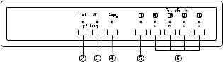
4. Lage und Funktion der Bedienelemente |
4. Operating Control and their Functions |
||||||
A Frontseite |
A Front Panel |
||||||
VCQ-6057 Farbe (Colour) |
|
|
|
|
|
|
|
VBQ-6045 S/W (B/W) |
|
|
|
|
|
|
|
|
|
|
|
|
|
|
|
(2) Verriegelung (Lock)
Durch Drücken der Taste Lock, für die Dauer von mind. 2Sek., wird die frontseitige Bedienung gesperrt. Eine erneute Betätigung der Taste für 2Sek. hebt die Sperrung wieder auf.
(3) VCR-Wiedergabe/Zoom-Funktion (VCR)
Zur VCR-Wiedergabe ist diese Taste zu betätigen. Bei gedrückter Taste sind „Sequenz, Quadbild und Kanalauswahl” unwirksam.
(2) und (3) Bildschirm-Menü
Durch gleichzeitiges Betätigen der Tasten (2) und (3) gelangt man zur Seite 1 des Bildschirm-Menüs. Die Betätigung der Taste (2) lässt die Seite 2 erscheinen.
Auf Seite 1 werden die Funktionen: Uhrzeit/Datum, Verweildauer und Kameratitel eingegeben, Seite 2 dient zur Konfiguration der Alarmverarbeitung.
Über die Tasten (6) wird der Cursor bewegt (s. Symbole über den Tasten) und die einzugebenden Textzeichen ausgewählt. Eine weitere Betätigung beider Tasten speichert die programmierten Daten, nach einer erneuten Betätigung gelangt man in die normale Betriebsart zurück.
(4) Sequenzschaltung, Vollbild-/Halbbildschaltung
Durch Betätigung der Taste Sequence wird in den automatischen Umlauf geschaltet, d.h. die Bilder aller angeschlossenen Kameras werden sequenziell im Vollbild-Modus gezeigt.
(5) Quadbild-Wiedergabe
Die Betätigung dieser Taste bewirkt die Umschaltung zwischen Quadbildund Vollbild-Wiedergabe.
(2) Lock
Security lock-out button. Push this button for 2 seconds to enable control panel lock-out function. Push this button again for 2 seconds to disable the function.
(3) VCR
Press this button for VCR-play back. In this mode, the output video is displaying the video signal from VCR.
(2) and (3) Menu
Push these two buttons simultaneously to get into menu setup mode and display page 1 of system setup menu. Push button (2) to display page 2 of the setup menu. Use page 1 to program time/date, dwell time and camera title and page 2 to configure alarm operations. Under menu setup mode, channel select buttons
(6) are used for cursor control and text selection to program the setup menu. Push the setup buttons simultaneously again to save the setting.
Push the setup buttons to save the setting and push the buttons to get back to ordinary operation mode.
(4) Sequence
Push this button to enable full page auto sequencing mode. Push this button again to disable it.
(5) Quad Display
Push this button to switch between quad/full screen display mode.

(6) Standbild- / Kameraanwahl-Tasten, FREEZE
Im Vollbild-Modus bewirkt das Betätigen der Tasten die Anwahl des entsprechenden Kameraeinganges.
Ausgehend vom Quadbild-Modus werden, durch Betätigung dieser Tasten, in den jeweiligen Quadranten Standbilder erzeugt (Einfrieren).
Video |
Quad |
Kanal-An- |
Funktion |
Freeze |
Taste (5) |
wahltaste (6) |
|
EIN |
EIN |
EIN |
Das Quadrantenbild wird eingefroren. |
EIN |
AUS |
EIN |
Darstellung des eingefrorenen Bildes im |
|
|
|
Vollbild-Modus |
AUS |
EIN/AUS |
EIN |
Darstellung des Kameraeinganges im |
|
|
|
Vollbild-oder Quad-Modus |
Die v.g.Tasten dienen auch zur Cursor-Bewegung sowie Text-Zeichenauswahl im Bildschirm-Menü.
(6) Channel Select Buttons, FREEZE
When operated in full screen display mode, these buttons are used to select specific camera to be displayed in full screen.
When operated in quad mode, these buttons are used to freeze any specific camera by pushing the corresponding button.
Video |
Quad |
Channel select |
Function |
Freeze |
button (5) |
buttons (6) |
|
ON |
ON |
ON |
Freeze specific camera video in quad |
|
|
|
screen mode |
ON |
OFF |
ON |
Call up specific camera input in |
|
|
|
Freeze mode |
OFF |
ON/OFF |
ON |
Call up specific camera input in Full |
|
|
|
screen mode |
These buttons are also used as cursor control and text select keys under setup menu mode.
B Rückseite |
|
|
|
B Rear Panel |
|
|
9 |
7 7 |
5 |
|
|
|
|
|
|
|
in |
|
RS- 3 |
|
|
hi-z |
|
|
|
|
|
3 4 |
out |
|
|
|
|
|
|
DC V amp |
ALARM I/O |
monitor |
vcr |
|
|
8 |
0 |
|
6 |
|
3 |
(7) Erdungs - Anschluss
Vorgesehen zum Anschluss der Betriebserde.
(8) Spannungsversorgung
Anschluss des mitgelieferten Netzadapters (12VDC)
(9) Fernbedienungs-/RS-232 - Anschluss
Anschluss für die jeweils vorgesehene Fernbedienung (s. Abschnitt 8/Zubehör), bzw. zur Geräte-Konfiguration über einen PC (s. Abschnitt 7).
(10) Alarm-Eingang (Alarm in)
9-pol. D-Sub-Buchse für den Anschluss der Alarm Ein-/Ausgangs-Kontakte. Als Alarm-Ausgang ist ein Relais-Umschaltkontakt vorhanden.
Pin - Belegung des Alarmanschlusses |
|
|
|||
Pin-Nr. |
Pin-Nr. |
Pin-Nr. |
|||
1 |
Eingang 1 |
4 |
Eingang 4 |
7 |
Schliess-Kontakt |
2 |
Eingang 2 |
5 |
Reset |
8 |
Gemeinsam |
3 |
Eingang 3 |
6 |
Masse |
9 |
Öffner-Kontakt |
(11) Eingangs-Abschluss
Impedanz-Schalter für jeden Kamera-Eingang, schaltet zwischen 75Ohm und HI-Z Impedanz. Ein falscher Abschluss setzt die Qualität des Videosignals herunter. Der Abschluss ist werkseitig auf 75Ohm gesetzt.
(12) Videoeingänge
BNC-Eingänge zum Anschluss der Kameras 1-4.
Im Quad-Modus werden die vier Eingänge wie folgt dargestellt:
(7) Chassis GND
This contact is provided to ground the chassis to the Earth Ground to prevent interference and electrical shock.
(8) Power Input
Power input connector. Use DC 12VDC
(9) Remote/RS-232 Connector
This 9 pin D-sub connector is used to provide remote control operation via the appropriate remote keypad (see section 8/Accessories) or a PC.
Please refer to section 7 for more details.
(10) Alarm In
This 9 pin D-sub connector is used for alarm sensor input and alarm output control connections. It provides Normally open and Normally closed contacts for alarm out control.
Pin assignment for alarm connector |
|
|
|||
Pin # |
Pin # |
Pin # |
|||
1 |
Sensor 1 |
4 |
Sensor 4 |
7 |
Normally open contact |
2 |
Sensor 2 |
5 |
Reset |
8 |
Common contact |
3 |
Sensor 3 |
6 |
GND |
9 |
Normally closed contact |
(11) Terminations
These impedance switches are used to provide proper termination for each camera input. These switches toggle between 75ohms and Hi-Z impedance. Incorrect termination will degrade the quality of the video signal. All video inputs not „looped through” to another device, the corresponding switches need to be set to 75ohms termination position. If another device is connected to video out loop through connector, set the corresponding termination switch to Hi-Z position. Any device connected to the video out loop through connectors needs to be configure to 75ohms. video termination. The factory default termination setting is 75ohms.

|
(12) Video IN Connectors |
|
|
These BNC connectors are used to connect to the video out from camera. Total |
|
|
four cameras can be connected to form a quad screen in the following mapping |
|
|
position. It is very important that each camera be correctly terminated. Please |
|
|
refer to Termination (#12) for proper impedance setting for each video in |
|
|
connector. |
|
1 |
|
|
2 |
|
|
|
|
|
3 |
4 |
|
|
|
|
(13) Videoausgang
BNC-Ausgangs-Buchsen zum Duchschleifen der Kamerasignale zu anderen Geräten.
(15) VCR-Eingang (VCR IN)
BNC-Buchse für den Anschluss des Videorecorder-Ausganges. Dies ermöglicht das Anzeigen und Programmieren des Menüs eines angeschlossenen Videorekorders.
Durch Betätigen der Taste (3) auf der Frontseite, schaltet man die Geräte auf die Betriebsart „VCR-Wiedergabe” um.
(16) VCR-Ausgang (VCR OUT)
BNC-Buchse für den Anschluss des Videorekorder-Einganges. Es werden immer alle 4 Kameras aufgezeichnet. Die Aufzeichnung wird von der Bildwahl über die Fronttastatur nicht beeinflusst.
(17) Monitor-Ausgang (LIVE)
BNC-Buchse für den Anschluss an einen Monitor-Eingang zur Wiedergabe von Live-Bildern. Die Live-Bilder können als Quadbild, Vollbild oder in sequenzieller Darstellung erfolgen.
(13) Video Out
Video out loop through connectors: These connectors are used to loop video signals from each camera out to other devices.
(15) VCR In
This BNC connector is to be connected to the „video out” from your VCR.
A pre-recorded quad screen video can be played back from the VCR and pass through to be displayed on the Monitor out (17) from this unit. This connector also allows user to display and program the on screen menu of the connected VCR without reconnecting the cables.
(16) VCR Out
This BNC connector is to be connected to the „video in” from your VCR. It will only provide a quad screen video to ensure an un-interrupted video
recording for all four cameras. The display video is not affected by the control panel and alarm status of the unit.
(17) Monitor Out
This BNC connector is to be connected to the „video in” of your monitor. It displays live video from camera inputs under live mode and playback video from VCR under VCR mode. The live video displayed here can be in quad screen, full screen, and auto sequencing mode depending on the operation.

5. Installation |
5. Installation Notes |
Vor der Installation Ihrer Anlage lesen Sie bitte auch die Betriebsanleitungen der anderen, für das System vorgesehenen Geräte. Der Quad-Splitter sollte, erst nach der Verkabelung aller Einheiten, an die Spannungsversorgung angeschlossen werden.
It is essential that your system be properly hooked up for proper results. Use the following diagram to install your system. Please power-off the unit before installation.
5.1 Grundsätzliches Verkabelungsschema mit Alarm |
5.1 Basic System Connection With Alarm Inputs and Output |
||||||
Ein-/Ausgang |
|
|
|
|
|
|
|
|
|
|
|
|
|
|
Camera 1 |
|
|
|
|
|
|
|
Camera 2 |
|
|
|
|
|
|
|
Camera 3 |
Quad |
Monitorto |
|
|
|
|
Monitor |
Camera 4 |
|
|
|
|
|
|
|
|
|
|
|
|
in |
|
|
|
Remote or RS- 3 |
|
Hi-Z |
|
|
|
|
|
|
|
|
3 4 |
out |
|
|
|
|
|
|
|
|
|
|
|
DC V amp |
ALARM monitor |
vcr |
|
ch ch ch3 ch4 |
|
|
|
|
to VCR |
|
VCR in |
|
|
|
VCR |
|
|
|
|
|
|
|
|
|
|
|
|
out |
VCR |
Quad-Darstellung |
|
|
|
|
|
|
|
||
AC Adapter |
|
|
|
Video |
|
Monitor |
|
|
|
|
|
Quad display monitoring |
|||
|
|
|
|
|
|
|
|
|
|
|
|
|
|
|
Processor |
|
|
|
|
Alarm reset |
|
|
|
sen. 1
sen. 2
sen. 3
|
sen. 4 |
|
|
6 |
COM NC |
NO |
. |
|
NO: Normaly open (Schliesser)
COM: Common (gemeinsam)
NC: Normaly closed (Öffner)

5.2 VCR-Wiedergabe
VCR-Wiedergabebetrieb, zur Darstellung und Vergrößerung aufgezeichneter Quad-Bilder (Zoom-Funktion). Durch Betätigung der VCR-Taste (3) auf der Frontseite der Geräte gelangt man in diesen Modus.
5.2 VCR Connection for Zoom on Playback Operation
VCR playback mode is designed to play pre-recorded quad screen video and display in either quad screen or expand any quadrant to full screen. Push VCR button (3) in the front panel to switch to VCR playback mode.
|
Quad-Bild / Quad display |
2fache Vergrößerung für jeden Quadranten / |
|
|
2x expansion for any quadrant |
|
|
in |
RS- 3 |
hi-z |
|
|
3 4 |
out |
|
|
|
DC V amp ALARM I/O |
monitor vcr |
|
AC Adapter
out Video
in Video
Video out |
|
Video in |
VCR |
|
5.3Videorekorder-Anschluss für Aufzeichnungsund Start/Stop-Betrieb
Für den automatischen Aufzeichnungsbetrieb auf einen VCR sind die Fernsteue- rungs-Funktionen „Aufzeichnung” und „Stop” des VCR mit den Ausgangskontakten des Quad-Splitters zu verkabeln. Die Aktivierung eines Alarm-Kontaktes löst die VCR-Aufzeichnung für die Dauer des Alarmzustandes aus.
•Stehen mehrere Alarme gleichzeitig an, wird das Bild der zuletzt aktivierten Kamera aufgezeichnet.
•Sollen ausschließlich Vollbilder aufgezeichnet werden, ist der RekorderEingang mit dem Anschluss LIVE zu verbinden. Es wird jeweils das Bild der zuletzt aktivierten Kamera aufgezeichnet.
5.3VCR Connection for Tape Recording Start and Stop Control
Connecting the contacts of VCR’s RECORD and STOP switch to the alarm output NC and NO contacts will allow you to use an ordinary VCR to record for longer period of time. Combined with alarm sensor detection, the VCR will record only when an alarm sensor is activated.
•If more than one sensor have been trigged, VCR will start to record after the last trigged event.
•In order to make use of the alarm called full screen display function the VIDEO IN connector from the VCR has to be connected to LIVE monitor connector of the device. If more than one sensor are trigged, VCR will then record all the events in full screen mode accordingly.
|
|
|
|
|
|
in |
Remote or RS- 3 |
|
Hi-Z |
|
|
|
|
|
|
|
3 4 |
|
|
out |
|
|
|
|
|
|
|
DC V amp |
ALARM |
monitor vcr |
ch |
ch |
ch3 |
ch4 |
Recorder SW
COM.
Stop SW
VCR
6 NC COM NO
Alarm trigged |
|
start recording |
|
NO ––> NC |
Recording stop |
Recorder |
Stop |
SW |
SW |
COM. (GND or VCC)
 t
t

5.4 Montage der Einschub – Winkelsets |
5.4 Use of Rack Mount Kit |
Siehe auch Abschnitt 8 / Zubehör |
See also chapter 8 / Optional Accessories |
1/2 19" Winkelset für den Einbau eines Einzelgerätes |
1/2 19" Rack mount kit for one unit |
x
x
4x
1/2 19" Winkelset für den Einbau von zwei Geräten |
1/2 19" Rack mount kit for two units |
x
x
4x 

5.5 Fernsteuerungs - Anschluss |
5.5 Remote Control Connection |
|
Rückfront |
Rear panel |
|
|
|
in |
RS- 3 |
hi-z |
|
|
3 4 |
out |
|
|
|
DC V amp ALARM I/O |
monitor vcr |
|
Fernbedienung /
Remote keypad
6. Bedienung |
6. Operating |
|
|
|
|
|
|
|
6.1 Bildschirm-Menü |
6.1 The Setup Menu |
|
|
|
|
|
|
|
Nach dem Einschalten des Gerätes zeigt der Monitor (Anschluss 17) die aktuellen Einstellungen. Der Monitor zeigt die Bilder der vier angeschlossenen Kameras im Quad-Modus.
Right after the unit is turned on, monitor connector 17 on the rear panel will display the last setting on the setup menu. The Monitor always displays
4 cameras in quad screen mode as follows:
1 |
2 |
3 |
4 |
6.1.1Seite 1 des Bildschirm-Menüs (Anzeige-Programmierung)
Es können zwei Menü-Seiten angewählt werden.
Seite 1 ist für die Programmierung von Verweildauer, Uhrzeit/Datum und Kameratitel vorgesehen, Seite 2 für die Konfiguration der Alarmverarbeitung. Mittels der Anwahltasten (6) wird der Cursor bewegt und die Selektion der Textzeichen vorgenommen. Zum Bewegen des Cursors werden die mit den Zeichen < und > gekennzeichneten Tasten benutzt, für die Auswahl der Textzeichen die Tasten
„ ” und „
 ”.
”.
6.1.1 Page 1 of the Setup Menu (Display Setting)
There are two pages in the Setup Menu.
Page 1 is used to program DWELL TIME, TIME, DATE, camera TITLE, and other display settings. Page 2 is used to program Alarm Operations.
Under this mode, channel selection buttons (6) on the front panel are used for cursor control and text selection. Use the cursor control buttons „<” and „>” to move the cursor to the entry in the menu desired to program, and use the text
select buttons „ ” and „
 ” to choose the right alphanumeric character to program.
10
Seite 1: |
Page 1: |
Programmierung von Zeit/Datum/Kameratitel und Bild-Intervallzeit |
Programming of time/date/camera title and picture dwell time |
CH |
TITLE |
DWELL TIME |
|
QUAD |
03 S |
1 |
__CH _1_ |
03 S |
2 |
__CH _1_ |
03 S |
3 |
__CH _1_ |
03 S |
4 |
__CH _1_ |
03 S |
VIDEO FREEZE |
|
ON |
VIDEO OUT: LIVE/MONITOR |
QUAD/VCR |
|
TITLE: |
ON |
ON |
TIME: 08 : 10 : 10 |
ON |
ON |
DATE: 04 –01 - 2000 |
ON |
ON |
6.1.1.1 Einstellung des Kameratitels (TITLE)
Für jeden Kamera-Kanal kann eine bis zu 8-stellige Bezeichnung eingegeben werden. Die verfügbaren Zeichen sind in der folgenden Tabelle gezeigt:
0, 1, 2, 3, 4, 5, 6, 7, 8, 9, ...
A, B, C, D, ... X, Y, Z a, b, c, d, ... x, y, z
:, <, >, -, x, /, ?, space.
6.1.1.1 TITLE Setup
The title menu permits the setup of separate titles for each video channel. Eight characters may be entered for each video channel. The available alphanumeric characters are:
0, 1, 2, 3, 4, 5, 6, 7, 8, 9, ...
A, B, C, D, ... X, Y, Z a, b, c, d, ... x, y, z
:, <, >, -, x, /, ?, space.
6.1.1.2 Einstellung der Bild-Intervallzeit (DWELL TIME)
Einstellung der Bild-Intervallzeit (Verweildauer) für jeden Kamera-Kanal sowie des Quadbildes im automatischen Umlauf, für den Monitor-Ausgang. Das Bildschirm-Menü zeigt die Nummern aller Kamera-Kanäle und die dazugehörige Verweil-dauer, die zwischen 00 bis 99 sek. eingegeben werden kann.
Einstellungen:
•-01 bis 99: Kamera-Kanal ist im automatischen Umlauf enthalten, das Bild wird für die angezeigte Dauer (in Sek.) wiedergegeben.
•-00: Kamera-Kanal wird im automatischen Umlauf nicht berücksichtigt (übersprungen).
6.1.1.3 Einfrieren (FREEZE)
Bei Stellung EIN kann das aktuelle Bild im Vollbildoder Quad-Betrieb eingefroren werden. Bei Stellung OFF ist die Funktion „Einfrieren“ deaktiviert.
6.1.1.4 Einstellung von Uhrzeit und Datum (TIME/DATE)
Die Anzeige von Uhrzeit und Datum kann sowohl auf dem Monitor eingeblendet werden. Der untere Bereich des Bildschirm-Menüs ist für die Eingabe der Zeit/ Datums-Information sowie auf welchem Monitor die Wiedergabe erfolgen soll, vorgesehen. Die Anzeige erfolgt im Format: Stunden : Minuten : Sekunden (HH:MM:SS) für die Uhrzeit und Monat-Tag-Jahr (MM-DD-JJ) für das Datum.
6.1.1.5 Anzeige von Uhrzeit/Datum/Kameratitel Ja/Nein
Ob und auf welchem Ausgang die einzelnen Anzeigen eingeblendet werden sollen, wird durch das Setzen von ON, bzw. OFF für jeden Ausgangs-Kanal bestimmt.
6.1.1.2 DWELL Time Setup
The Dwell time menu permits setting the dwell time for all cameras and the quad screen on the Live output channel. The menu shows a table of all cameras and associated dwell time. Dwell time can be programmed by setting a number between 00 to 99 for each channel in the menu.
•-01 through 99: Adds the camera input to the auto switching sequence, with the corresponding dwelll time in seconds
•-00: Skips the camera input in the auto switching sequence.
6.1.1.3 FREEZE
This entry is used to enable or disable the video freeze operation.
1.If this entry is set to ON, user can freeze the specific camera video under live quad display mode by pressing corresponding channel buttons on the front panel. However, user can only call up specific camera if the unit is operated under full screen display mode.
2.If this entry is set to OFF, there will be no video freeze function. Under this mode, the unit will only call up specific camera in live full screen display by pressing corresponding channel buttons regardless the original display mode of the unit.
6.1.1.4 TIME/DATE Setup
Time and date information can be displayed on the video output channel through both Live and Quad connector. Bottom of page 1 is used to set the values of time and date and also to enable or disable the display at each output channel.
The time will display in the HH:MM:SS format and the date will display in the
MM-DD-JJ-Format.
6.1.2Seite 2 des Bildschirm-Menüs (Konfiguration der Alarmverarbeitung)
Um auf die Seite 2 des Bildschirm-Menüs zu gelangen die Taste (2) betätigen. Diese Seite ist für das Konfigurieren der Alarmverarbeitung, wie Kontakt-Typ, Ansprech-Empfindlichkeit, Alarmdauer, akustische Alarmgabe, Videoverlustalarm und Videoverlustrelais vorgesehen.
6.1.1.5TITLE/TIME/DATE Disable and Enable in Live and Quad Video Output Channel
The title/time/date display on each output channel can be enabled or disabled by setting ON or OFF in the corresponding entry.
6.1.2 Page 2 of the Setup Menu (Alarm Setting)
Push setup buttons (2) simultaneously again to display page 2 of the setup menu on the screen. This alarm setting menu is used to set the desired alarm configuration like sensor type, sensor sensitivity, alarm hold duration and buzzer.
11
 Loading...