


User Manual
1.3/2.0/3.0 Mega-Pixel IP Camera |
|
|
GXC-1605M |
GXD-1610M/IR |
GXC-1606M/IR |
GXC-1710M |
GXD-1710M/IR |
GXB-1710M/IR |
GXC-1720M |
GXD-1720M/IR |
GXB-1720M/IR |
1
Betriebsanleitung |
|
Installation and Operating Instructions |
www.videor.com |
Mode d’emploi |
www.eneo-security.com |
Instrukcja instalacji i obsługi |
|
2
Table Of Contents |
|
SAFETY PRECAUTIONS ............................................................................. |
5 |
1. PRODUCT FEATURES............................................................................. |
6 |
1.1 PRODUCT INSTRUCTIONS ..................................................................... |
6 |
1.2 PRODUCT FEATURES ........................................................................... |
8 |
2. DESCRIPTION OF THE SURFACE ......................................................... |
9 |
2.1 THE IP BOX CAMERA (POE)................................................................. |
9 |
2.2 THE FIXED IP INDOOR/ OUTDOOR MINI-DOME (POE).......................... |
11 |
2.3 THE BULLET IP CAMERA INDOOR/ OUTDOOR (POE)............................ |
12 |
2.4 THE RESET BUTTON .......................................................................... |
14 |
2.5 THE ALARM WIRING DIAGRAMS ........................................................... |
15 |
2.6 THE USB FUNCTION .......................................................................... |
18 |
3. INSTALLATION ...................................................................................... |
19 |
3.1 HARDWARE INSTALLATION .................................................................. |
19 |
3.2 THE INSTALLATION OF THE FIXED IP INDOOR MINI-DOME (POE)........... |
20 |
3.3 THE INSTALLATION OF THE FIXED IP OUTDOOR MINI-DOME (POE) ....... |
21 |
3.4 PLACING A DESICCANT PACK INSIDE THE CAMERA ............................... |
22 |
3.5 UPDATING SYSTEM SOFTWARE .......................................................... |
23 |
4. Network Configuration.......................................................................... |
24 |
4.1 CABLE CONNECTIONS........................................................................ |
24 |
4.1.1 Connect to a computer ...................................................................................................................... |
24 |
4.1.2 Connect to a LAN Hub (INTRANET) ............................................................................................. |
24 |
4.2 CONFIGURE YOUR IP CAMERA NETWORK SETTINGS ........................... |
25 |
4.2.1 Enable DHCP Function..................................................................................................................... |
25 |
4.2.2 Set IP Address ................................................................................................................................... |
25 |
4.3 TCP/IP COMMUNICATION SOFTWARE ................................................. |
26 |
3
|
4.4 TCP/IP INSTALLATION ....................................................................... |
28 |
|
4.5 TCP/IP CONFIGURATION SETTING ...................................................... |
29 |
|
4.6 CONNECTION TESTING....................................................................... |
30 |
5. Operating Instructions for Image Software and Network.................. |
32 |
|
|
5.1 MICROSOFT INTERNET EXPLORER ...................................................... |
33 |
5.1.1 |
Connecting the IP camera ................................................................................................................ |
33 |
5.1.2 |
Live Video ........................................................................................................................................ |
34 |
5.1.3 |
Setup................................................................................................................................................. |
38 |
6. ADVANCED OPERATION...................................................................... |
91 |
|
7. SPECIFICATIONS................................................................................... |
94 |
|
8. Functions of client PC......................................................................... |
100 |
|
APPENDIX 1. –How to run IP Camera UPnP ......................................... |
101 |
|
APPENDIX 2. –Register as a DDNS member ........................................ |
111 |
|
4

SAFETY PRECAUTIONS
All the following safety and operational instructions to prevent harm or injury to the operator(s) or other persons should be read carefully before the unit is activated.
WARNING
To prevent fire or shock hazard, avoid exposing this unit to rain or moisture. Do not block ventilation openings.
Do not place anything on top of the unit that might spill or fall into it.
Do not attempt to service this unit yourself, as opening or removing covers may expose you to dangerous voltage or other hazards. Please refer all servicing to your distributor/ retailer.
Do not use liquid cleaners or aerosols for cleaning.
To prevent fire or electric shock, do not overload wall outlets or extension cords. PoE warning : If the PoE injector is used instead of the supplied power adaptor, all of the wiring to and from the injector must be routed/ installed inside a building/ plant and never routed/ installed outside of the building/ plant.
Please only select a power adapter or power certified by UL and marked at 24Vac / 60 Hz, minimum 1A, class 2 or LPS.
The IP Box Camera and the Indoor Mini-dome are for Indoor use only.
CAUTION
RISK OF EXPLOSION IF BATTERY IS REPLACED BY AN INCORRECT TYPE. DISPOSE OF USED BATTERIES ACCORDING TO THE INSTRUCTIONS.
5
1.PRODUCT FEATURES
1.1Product Instructions
The 1.3 mega-pixel IP camera series is a high performance mega-pixel network camera which is equipped with a high resolutions SONY 1.3M CMOS sensor and a resolution of up to 1280 x 1024 (SXGA). This powerful new series enables you to see fresh images in fine detail aided by a spectrum of high resolutions plus WDR technology that combats problems like capturing images against backgrounds of bright light. In addition the series is equipped with the dynamic H.264 video compression format, the compression codec which ensures top image quality at a low bit rate. The 3GPP installed mobile phone helps you see live scenes via the Internet as well. And this series provides you with freshly designed, simultaneous video codec streams of H.264, MPEG4 and MJPEG. This function, the multi-profile function, can simultaneously use different rates of resolutions while allowing maximum 3 video codecs to connect with computers at the same time. This IP camera not only offers the highest resolutions in images in the field, but also day and night, preand post-alarm, and ePTZ functions.
This 2.0 mega-pixel IP camera series is a high performance mega-pixel network camera which is equipped with a high resolutions OV 2M CMOS sensor and a resolution of up to 1920x1080 (FULL HD). This powerful new series enables you to see fresh images in fine detail aided by a spectrum of high resolutions. In addition the series is equipped with the dynamic H.264 video compression format, the compression codec which ensures top image quality at a low bit rate. The 3GPP installed mobile phone helps you see live scenes via the Internet as well. And this series provides you with freshly designed, simultaneous video codec streams of H.264, MPEG4 and MJPEG. This function, the multi-profile function, can simultaneously use different rates of resolutions while allowing maximum 3 video codecs to connect with computers at the same time. This IP camera not only offers the highest resolutions in images in the field, but also day and night, preand post-alarm, and ePTZ functions.
6
The 3.0 mega-pixel IP camera series is a high performance mega-pixel network camera which is equipped with a high resolutions SONY 3M CMOS sensor and a resolution of up to 2048 x 1536. This powerful new series enables you to see fresh images in fine detail aided by a spectrum of high resolutions. In addition the series is equipped with the dynamic H.264 video compression format, the compression codec which ensures top image quality at a low bit rate. The 3GPP installed mobile phone helps you see live scenes via the Internet as well. And this series provides you with freshly designed, simultaneous video codec streams of H.264, MPEG4 and MJPEG. This function, the multi-profile function, can simultaneously use different rates of resolutions while allowing maximum 3 video codecs to connect with computers at the same time. This IP camera not only offers the highest resolutions in images in the field, but also day and night, preand post-alarm, and ePTZ functions.
Following are the special powers featured in this series.
SXGA / 1280x1024 pixels (1.3 mega-pixel)
The series lets you view the video feed with a large field of high resolutions at SXGA / 1280x1024 pixels that provide you with clear images in great detail.
FULL HD / 1920x1080 pixels (2.0 mega-pixel)
The series lets you view the video feed with a large field of high resolutions at FULL HD / 1920x1080 pixels that provide you with clear images in great detail.
2048 x 1536 pixels (3.0 mega-pixel)
The series lets you view the video feed with a large field of high resolutions at 2048 x 1536 pixels that provide you with clear images in great detail.
WDR (Wide Dynamic Range)
Besides, the series provides WDR technology which is aimed at coping with problems like poor quality images shot against a strong backlight. WDR uses two shutter speeds in alternative video fields, high and normal, and combines these two fields into one frame. It allows every detail to be captured accurately, even if one portion is bright while other portions are dark. As a result, combined fields yield a frame of high quality images.
7
H.264 compression
Currently, the H.264 is the most common and dynamic video compression format and a powerful compression codec which delivers superior image quality at a low bit rate.
3GPP
Users can view a live scene via the Internet with a 3GPP installed mobile phone.
(Note: The 3G network bandwidth is limited; you can't use too large video size on your cell phone.) Video Settings:
Video Profile 1
Maximum frame rate: 3 fps
Intra Frame Period: 1 S
Constant bit rate: 64 Kbps
In short, the series provides quality images and professional surveillance functions for comprehensive security applications.
1.2 Product Features
Adopts TI TMS320DM365/TMS320DM368 digital media processor.
SONY 1.3M CMOS sensor/ OmniVision 2M CMOS sensor/ SONY 3M CMOS sensor. Simultaneous H.264, MPEG4 and MJPEG video compression.
Three multi-profile applications: Selectable resolutions, frame rates, qualities, and image chopping.
Supports WDR.
Built-in IR-cut filter provides high quality images in low light conditions.
Two-way audio.
3GPP mobile surveillance.
Advanced motion detection ( 512 zones. Sensitivity: 0 -100 % ).
Built-in SD / SDHC card for schedule and alarm recording.
Supports ONVIF.
Full range of power options: DC12V / AC24V / PoE ( IEEE 802.3af ).
8

2.DESCRIPTION OF THE SURFACE
2.1The IP Box Camera (PoE)
Front Panel and Rear Panel: |
|
|||||||||
|
|
|
|
-- Front Panel -- |
-- Rear Panel -- |
|||||
1 2 |
|
1/4 -20UNC |
|
|||||||
|
|
|
|
|
|
|
|
|
|
|
|
|
|
|
|
|
|
|
|
|
|
|
|
|
|
|
|
|
|
|
|
|
|
|
|
|
|
|
|
|
|
|
|
|
|
|
|
|
|
|
|
|
|
|
|
|
|
|
|
|
|
|
|
|
|
|
|
|
|
|
|
|
|
|
|
|
|
|
|
|
|
|
|
|
|
|
|
|
|
|
|
|
|
|
|
|
|
|
|
|
|
|
|
|
|
|
|
|
|
|
|
|
|
|
|
|
|
|
|
|
3
1.Light Sensor: Registers the quality of light in the camera’s environment, and controls the iris shuttle to provide better information concerning the light.
2.MICROPHONE: The IP Camera has an additional audio function. The device has a microphone built into its front panel which records sound.
3.POWER indicator: Indicates the power status of the unit.
4.Plug Inlet: A DC 12V inlet that connects to an external power supply.
5.Plug Inlet: An AC 24V inlet that connects to an external power supply.
6.ETHERNET 10/100 Connector: This is a standard RJ-45 connector for 10/100 Mbps Ethernet networks. PoE (Power over Ethernet) function: Provides power to the device via the same cable as used for the network connection.
7.RESET: Recover to factory default. (Refer to section 2.4 The Reset Button.)
8.VIDEO OUT Connector: The connector provides the unit’s composite video signals to a monitor. (This connector adjusts and improves the images.)
9.USB port: The user can use a USB device cable to connect the IP camera to the USB port on the PC.
10.LED indicator: The green light indicates the unit is activating and the SD card cannot be removed.
11.AUDIO IN: The connector is used to connect the audio output from other devices to the camera.
12.SD/ SDHC CARD slot: This is used for updating system software and archiving / accessing critical images.
13.GPIO: This is a 6-PIN connector including the ALARM IN/OUT, RS-485, DC OUTPUT and GROUND items for connecting with external devices.
14.AUDIO OUT: Provides the camera’s audio signal to a speaker or stereo.
9

Flank Panel:
|
|
IRIS |
|
|
1.ALM-OUT A |
7.RS-485:D+ |
1. AES |
1 |
3 |
2.ALM-OUT B |
8.RS-485:D- |
2. DC IRIS |
|
|
3.ALM-IN + |
9.DC-OUT(5V) |
|
|
|
|
2 |
4 |
||
4.ALM-IN - |
10.GND |
3. DHCP |
||
5.ALM-RST + |
11.AUDIO-IN |
4. STATIC IP |
|
|
6.ALM-RST - |
12.AUDIO-OUT |
|
||
|
|
|
||
|
1 |
|
|
2 |
1. IRIS: Auto iris connector.
This camera works with a DC drive auto iris lens. Please refer to the pin assignment marked on the camera when connecting the auto iris lens
2. DIP Switch:
1.AES: Auto electric shutter.
2.DC IRIS: Use an auto iris (DC drive)
3.DHCP: Turn On / Turn Off to use the DHCP protocol. If the switch points upwards, the device can obtain an IP address from the DHCP server via the network.
4.STATIC IP: If the switch points down, the device can’t obtain an IP
address from the DHCP server. This option is needed to configure the network communication settings.
(*In the default factory configuration, this DIP Switch is in the Down position.)
10
2.2 The Fixed IP Indoor/ Outdoor Mini-Dome (PoE)
|
|
|
|
|
|
|
8 |
|
|
|
|
|
8 |
|
|
|
|
|
|
|
|
|
|
|
|
9 |
|
|
|
|
|
|
|
|
9 |
|
|
|
|
|
|
|
|
|
|
|
|
|
|
|
|
|
|
10 |
|
|
|
|
|
|
|
|
10 |
|
|
|
|
|
|
|
|
|
|
|
|
|
|
|
|
|
|
|
|
1 |
2 |
3 |
4 |
5 |
6 |
7 |
1 |
2 |
3 |
4 |
5 |
6 |
7 |
1.Power Input: DC 12V input connects to an external power supply.
2.Power Input: AC 24V input connects to an external power supply.
3.ETHERNET 10/100 Connector: This is a standard RJ-45 connector for 10/100 Mbps Ethernet networks. PoE (Power over Ethernet) function: Provides power to the device via the same cable as used for the network connection.
4.AUDIO IN: Connector is used to connect the audio output from other devices to the IP camera.
5.VIDEO OUT Connector: Connector provides Composite video output.
6.AUDIO OUT: Provides IP camera audio signal to an external device.
7.GPIO: 6-PIN connector for digital I/O, DC output and GROUND for connecting with external devices.
8.USB port: Connects IP camera to USB port on a PC.
9.SD/ SDHC CARD slot: Used for updating system software and archiving video.
10.RESET: Recover to factory default. (Refer to section 1.4 The Reset Button.)
11

2.3 The Bullet IP Camera Indoor/ Outdoor (PoE)
The component parts ( the internal view ).
Dismantle the bullet IP camera to see its different parts. The picture here shows you the internal component items making up the product.
SCREWS
SUN SHIELD
SD PCB 


LENS FAN
REAR CASE
MIDDLE CASE
SENSOR PCB POWER PCB WATERPROOF RUBBER
PCB PLATE
IR PCB
FRONT CASE
Camera with bracket ( the external view ).
The picture here shows the camera's exterior, with the bracket screwed in and fixed to it. The bracket enables you to easily mount the camera on a wall, turned at the angle you want.
NOTE: Use the 2 screws to screw the sun shield (above) into the 2 extreme holes indicated in the bullet camera (below) to get an unobstructed viewing angle.
Please don’t use the middle hole in the camera, as that will block the view.
12

The PCB board:
6 |
7 |
8 |
9 |
10 |
1 |
2 |
3 |
4 |
5 |
1.Plug Inlet: An AC 24V inlet that connects to an external power supply.
2.ETHERNET 10/100 Connector: This is a standard RJ-45 connector for 10/100 Mbps Ethernet networks. PoE (Power over Ethernet) function: Provides power to the device via the same cable as used for the network connection.
3.Plug Inlet: A DC 12V inlet that connects to an external power supply.
4.GPIO: This is a 6-PIN connector including the Digital output/input, DC output and
GROUND items for connecting with external devices.
5.VIDEO OUT Connector: The connector provides the unit’s composite video signals to a monitor. (This connector adjusts and improves the images.)
6.AUDIO IN: The connector is used to connect the audio output from other devices to the camera.
7.USB port: The user can use a USB device cable to connect the IP camera to the USB port on the PC.
8.AUDIO OUT: Provides the camera’s audio signal to a speaker or stereo.
9.SD/ SDHC CARD slot: This is used for updating system software and archiving / accessing critical images.
10.RESET: Recover to factory default. (Refer to section 2.4 The Reset Button.)
13
2.4 The Reset Button
The Reset Button will bring the IP camera back to its factory default settings. Press the Reset Button for about 10 seconds. A Blue screen will be displayed and a text that says “RESETTING…” will appear. The device will then auto reboot. All settings will then be back to default. The following items will return back to default.
[SETUP]
Network Setup
a.LAN Settings (You can manually reset this function by yourself.)
b.PPPOE Settings (You can manually reset this function by yourself.)
Dynamic DNS
a.DYNAMIC DNS SETTING (You can manually reset this function by yourself.)
IMAGE SETUP
a.Privacy Mask Setting
b.IMAGE SETTINGS
AUDIO AND VIDEO
a.VIDEO PROFILE 1
b.VIDEO PROFILE 2
c.AUDIO SETTINGS
MOTION DECTION
a.Video Motion setting
TIME AND DATE
a.TIME CONFIGURATION
b.AUTOMATIC TIME CONFIGURATION
c.SET DATE AND TIME MANUALLY
Event Setup
a.Server
b.Media
c.Event
d.Recording
[ADVANCED]
DI and DO
a.DI and DO
b.LED
c.VIDEO OUTPUT
RS-485 (for the IP Box Camera only)
a.RS-485
ICR
a.ICR
HTTPS
a.HTTPS
Access List
a.Allow List
b.Deny List
14
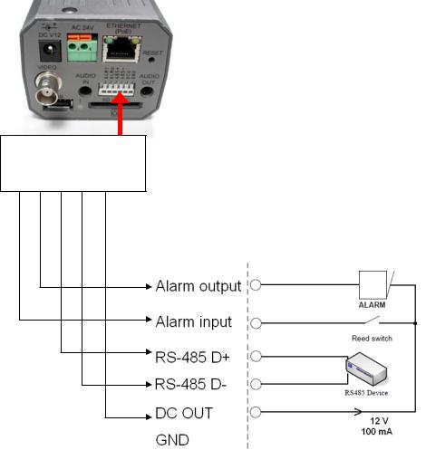
2.5 The Alarm wiring diagrams
The IP Box Camera (PoE)
ALM i ALM o 485 + 485 - DC o GND
+12V
+12V
15

The Fixed IP Indoor/ Outdoor Mini-Dome (PoE)
GND 12V+ Di - Di + Do - Do +
+12V
+12V
16
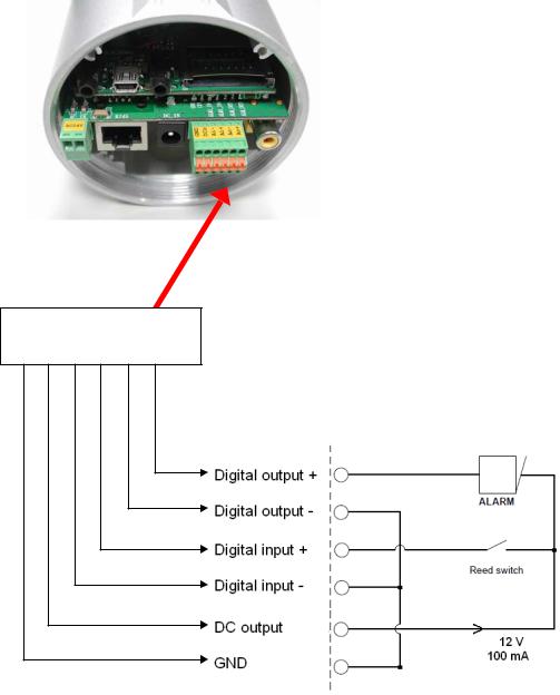
The Bullet IP Camera Indoor/ Outdoor (PoE)
GND 12V+ Di - Di + Do - Do +
+12V
+12V
17

2.6 The USB function
The IP camera can provide two separate functions by connecting the IP camera with a PC via the USB connector.
1.Using an SD card as a card reader.
Insert an SD card into the IP camera and then connect to the PC. You may then transfer files between the SD card and the PC. Once you've connected your IP camera to your computer Windows will detect the connection and ask you what you want to do with the SD card.
2.Using an SD card as a configuration tool.
Before using the USB configuration setting page, please remember to remove the SD card or your PC will read the SD card and won’t show this window.
DHCP ON
DHCP OFF
(default)
Network
Setting
NOTE: After changing the settings, please click the “Apply” button. All of the options will be effective after removing the USB connector.
NOTE: After the IP address has been changed and/ or reset, please unplug the network cable, then plug it once again to make sure the network connection is in normal mode.
18
3. INSTALLATION
Please follow the instructions and the diagram below to set up the system.
NOTE: The IP camera is linked by its Video Out connection via a BNC connector to a monitor's Video In connection. If this connection is there, you can see some information on the monitor screen, such as the IP camera factory default Static IP address (192.168.1.10). But the IP camera Static IP address can only appear if there is a connection between the IP camera and another device. If there is no such connection, the IP camera factory default Static IP address will not appear on the monitor screen.
3.1Hardware Installation
1.Plug in the power connection to the IP camera.
2.Plug in the IP camera cable.
3.Confirm the correct network connection status (PC/ HUB/ IP camera).
4.In the PC IE Browser, key in the camera’s IP online to link up to the live first page.
NOTE: Red light power indicator of the IP Box Camera: it flashes when the power supply is on.
Two-color network indicator:
1.It is off when the network is disconnected.
2.The green light goes on when the network is connected; the orange light flashes indicate the network connection status.
19

3.2 The Installation of the Fixed IP Indoor Mini-Dome (PoE)
Attaching the dome via the flank.
Step 1. Fix the iron base to the ceiling with the nails and the nylon nails.
Step 2. Detach the top iron base from the dome camera. Put the flat metal strip atop the dome, and screw it in with the two screws. Attach the iron base atop the dome and screw it in place.
Step 3. Insert the cable in the flank port.
Step 4. Attach the flank panel cover on top of the port. Screw the cover in over the flat metal strip.
Step 5. The dome is now attached to the ceiling.
NOTE: The dome camera is available from us. The other component parts are also available, but optional for the buyer.
20

3.3 The Installation of the Fixed IP Outdoor Mini-Dome (PoE)
Attaching the dome via the flank.
Step 1. Fix the iron base to the ceiling with the nails and the nylon nails.
4*25mm(L)_
 SELF TAPPING SCREWS
Step 2. Unscrew the flank panel cover and take it off.

 M3*5(L)_SCREW
Step 3. Detach the top iron base from the dome camera. Put the flat metal strip atop the dome, and screw it in with the two screws. Attach the iron base atop the dome and screw it in place.

 M3*5mm(L)_SCREW
Step 4. Insert the cable in the flank port.
Step 5. Attach the flank panel cover on top of the port. Screw the cover in over the flat metal strip.
M4*17mm(L)_SCREW |
NOTE: |
Wrong |
Right |
Step 6. The dome is now attached to the ceiling.
NOTE: The dome camera is available from us. The other component parts are also available, but optional for the buyer.
21

3.4 Placing a Desiccant Pack Inside the Camera
The outdoor mini-dome/ bullet camera comes with a desiccant pack which is placed inside the camera using a two-sided adhesive tape. The desiccant pack is for reducing the moisture and humidity content inside the camera and prevents moisture from condensing on the lens or its cover.
If the user decides to remove the camera cover after more than a few months of camera use, remove the used desiccant pack as well and place the replacement pack inside the camera.
1.Stick the piece of desiccant pack to the inner side of the camera.
2.Then use a two-sided adhesive tape to fix the desiccant pack.
3.Reattach the cover of the camera.
The Outdoor Mini-dome Camera: |
|
The Bullet Camera: |
|||||||
|
|
|
|
|
|
|
|
|
|
|
|
|
|
|
|
|
|
|
|
|
|
|
|
|
|
|
|
|
|
|
|
|
|
|
|
|
|
|
|
|
|
|
|
|
|
|
|
|
|
|
|
|
|
|
|
|
|
|
|
|
|
|
|
|
|
|
|
|
|
|
|
|
|
|
|
|
|
|
|
|
|
|
|
|
|
|
|
|
|
22
3.5 Updating System Software
If the system software of the IP Camera needs to be upgraded, please take the following steps to safely process it.
Important: Before carrying out the following procedures, please ensure the SD card is working and the file of the system firmware is intact
1.Create a directory named UPGRADE (upper-case or lower-case letters are no difference) in the SD card if it does not exist.
2.Copy the file of UPDATE.BIN to the UPGRADE -directory.
3.If the IP Camera is running, please power it off first.
4.Insert the SD CARD into the IP Camera.
5.Remove the Ethernet cable from the RJ-45 port and then power on the IP Camera.
6.In 5 to 10 seconds, a message reading "UPDATE PROCESSING" will show up on the screen on a blue background; if not, please check out steps 1 to 6 carefully or else inform your technical support while ignoring the following steps.
7.DO NOT power off the IP Camera while this update process is running until the message "UPDATE OK RESET PLEASE" appears on the screen; it might take 15 to 30 seconds to appear.
8.If the message "UPDATE NG RESET PLEASE" appears rather than "UPDATE OK RESET PLEASE", please write down the error messages shown on the screen and inform your technical support, while ignoring the following steps.
9.Power off the IP Camera when this update process is finished, then remove the SD card from the IP Camera.
10.Reconnect the Ethernet cable to the RJ-45 port if necessary.
11.Power ON the IP Camera and it will work normally if the entire update procedure goes correctly.
12.Verify the version of the system software.
WARNING:
Steps 1 to 2 have to be done on a PC.
Make sure the file of UPDATE.BIN is a correct one in step 2, or the IP Camera will not work normally after being updated.
If the power of the IP Camera is suddenly lost in step 7, please remove the SD card first and turn on the IP Camera next to test its operation. If the IP Camera remains working normally, please go back to step 3; otherwise, please inform your technical support.
In step 9, if the SD card is not removed and the IP Camera does not get online as well, the updating process must be repeated again after rebooting the IP Camera.
Make sure that the SD card is inserted in a correct position in step 4, or the IP Camera will suffer permanent physical damage.
If the message "CSUM ERROR" appears in step 7, it implies a problem in the file of UPDATE.BIN.
Don’t interrupt the process while the unit is updating itself; proceed with an SD card not including any system software of the unit, or else the unit will crash.
23

4.Network Configuration
4.1Cable Connections
Please follow the instructions below to connect your IP camera to a computer or a network and to choose a proper RJ-45 cable configuration for connections.
Physical specifications of the RJ-45 cable for Ethernet
Wire Type |
Cat. 5 |
Connector Type |
RJ-45 |
|
|
Max. Cable Length |
100 m |
|
|
Hub Wiring Configuration |
Straight Through |
|
|
PC Wiring Configuration |
Straight Through |
|
|
4.1.1 Connect to a computer
Use a straight LAN cable to connect directly to a computer.
LAN CAMERA
CROSSOVER CABLE
RJ-45
TO PC LAN CARD
CROSSOVER CABLE PIN CONFIGURATION
4.1.2 Connect to a LAN Hub (INTRANET)
The RJ-45 PIN configuration for connecting with a LAN Hub is shown below.
TO PC NETWORK CARD
LAN CAMERA
RJ-45
uplink |
24
4.2 Configure Your IP Camera Network Settings
Upon connecting with the network hardware, you need to activate the network function and configure the proper network settings of the IP camera.
4.2.1 Enable DHCP Function
Note: The IP Camera default setting is DHCP ON. Users can obtain an IP address automatically from the DHCP server.
The IP box camera:
This function can only work if the LAN, which the unit is connected to, has a DHCP server. If the DHCP server is working, please move the dip switch points up to 3 on the flank panel; now the IP camera will obtain an IP address automatically from the DHCP server. In this instance, please skip section 4.2.2 (Set IP address) and follow section 4.3 (TCP/IP Communication Software).
The IP indoor/ outdoor mini-dome & the IP bullet camera:
This function can only work if the LAN, which the unit is connected to, has a DHCP server. If the DHCP server is working in the LAN, please plug the USB connector into your PC’s USB socket and the other end of the connector in the camera. A window pops up asking if you want to "Run the program", "Open folder to view files", or "Take no action". Choose "Run the program" and click "OK", and the "USB configuration" window will pop up. Set the Network setting and turn on the DHCP setting to use the DHCP protocol. The IP Camera will obtain an IP address automatically from the DHCP server.
4.2.2 Set IP Address
You need to set an IP address for the unit if the LAN unit isn’t connected to a DHCP server. Otherwise, please follow the instructions given below:
Note: The default static IP is 192.168.1.10.
Set the IP, MASK and GATEWAY. The following is a sample setting.
IP: |
192.168.1.X |
MASK: |
255.255.255.0 |
GATEWAY: |
0.0.0.0 |
NOTE: When only one unit of the IP camera is connected to a computer or LAN, you can freely assign an IP address for the IP camera. For example, there is a range of IP camera IP addresses from 192.168.1.1 to 192.168.1.255. You can pick one for use from the range of the IP. It’s not necessary to set MASK and GATEWAY; leave the settings as default.
When an IP camera is connected to a WAN, you must acquire a unique, permanent IP address and correctly configure the MASK and GATEWAY settings according to your network architecture. If you have any questions regarding those settings, please consult a qualified MIS professional or your ISP.
NOTE: When connecting to a network, each connected IP camera must be assigned a unique IP, which must be in the same class type as your network address. IP addresses are written as four sets of numbers separated by periods; for example, 192.168.1.1 Therefore, if the connected network is identified as Class C, for example, the first three sets of numbers of the IP camera IP address must be the same as the network address. If the connected network is identified as Class B, the first two sets of numbers of the IP camera IP address must be the same as the network address. If you have any questions regarding these settings, please consult a qualified MIS professional or your ISP.
25
4.3 TCP/IP Communication Software
Follow the procedure below to install the TCP/IP communication program in your computer.
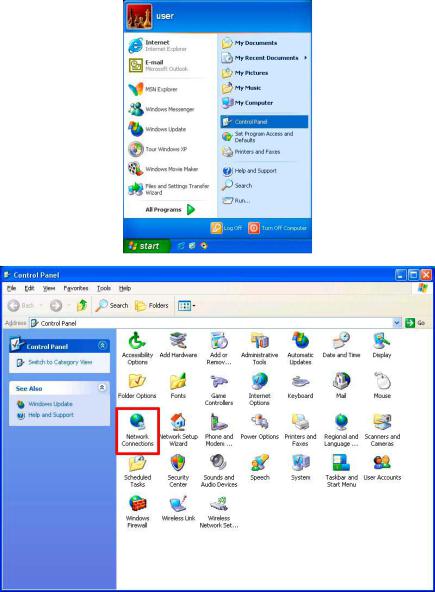
1.Click Start, and then click Control Panel.
2.Double click the Network Connections icon to enter the windows.
4.Right-click your network connection and then click Properties.
26
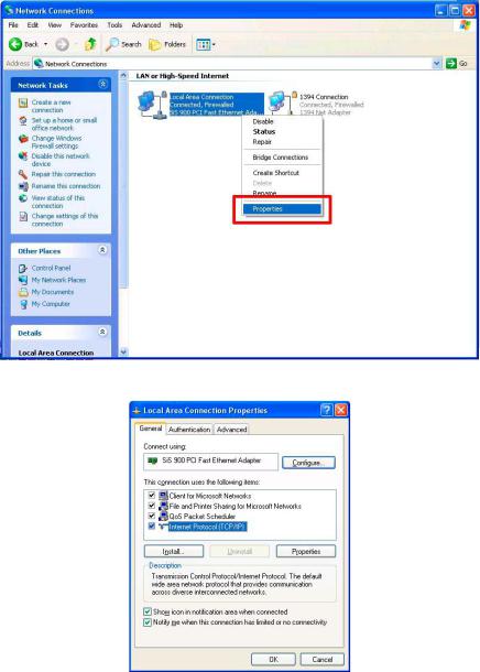
5.On the General tab, check if the Internet Protocol (TCP/IP) is included in the list. If the TCP/IP is included, please process section 4.5. If it is not included, please follow section 4.4 to install the TCP/IP.
27

4.4 TCP/IP Installation
On the General tab of the Connection Properties, under “This connection uses the following items”, click Internet Protocol (TCP/IP). Then click Install. Select Protocol from the network component type then click Add. Select Microsoft TCP/IP from the network protocol then click OK. Click Close to return to the Network Connections window.
28

4.5 TCP/IP configuration setting
Click Start > Control Panel > Network Connections.
Select Internet Protocol (TCP/IP), and then click Properties.
Before processing the IP camera installation in a WAN, please make sure the Internet connection works properly. If not, please contact your ISP provider.
If you are using a DHCP server, please select Obtain an IP address automatically. Any assigned IP address for the connected IP cameras must be in the same class type as the server. If there is no DHCP server, please select specify an IP address enter the IP address, subnet mask and default gateway of your choosing of your PC. This IP address must be different from other network IP devices but in the same class type.
NOTE: The IP address of an IP camera in a network must be unique to itself as opposed to those of the other chosen PCs, but in the same class type.
29
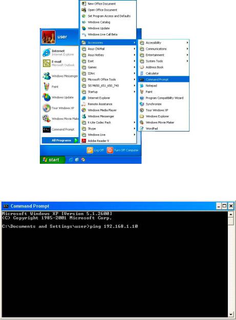
4.6 Connection Testing
With the previous settings, follow the instructions below to ensure whether you have established
the connection successfully.
1.Click Start > All Programs > Command Prompt.
2.Enter ping XXX.XXX.XXX.XXX (the camera’s IP address), then enter. (See the sample screen below).
**This is the IP address for an IP camera that is assigned for the connected IP camera.
30
 Loading...