


INSTALLATION AND OPERATION MANUAL
for
PXC-2080&6
Table of contents
1.Safety Instructions and Notes…....................................................................................................... 3
2.General Descriptions............................................................................……………………………... 3
3.Supplied Items......................................................................................……………………………... 4
4.Part names…………………………….…...................................................…………………………... 5
5.Installation Instructions......................................................................................……………………... 7
6.Setup Menu ……………............................................................................…………………………... 9
7.Specifications ……………………………………………….................................................................. 27
8.Dimensional Drawings ……………………………………………............................................................29
1

WARNING To prevent fire or shock hazard, do not expose the unit to rain or moisture.
The symbol is intended to alert the user to the presence of important operating and maintenance(servicing) instructions in the literature accompanying the unit.
The symbol is intended to alert the user to the presence of uninsulated "dangerous voltage" within the product's enclosure that may be of sufficient magnitude to constitute a risk of electric shock to persons.
Caution
To prevent electric shocks and risk of fire hazards, do NOT use other than specific power source.
Warning(NTSC version) -- This equipment has been tested and found to comply with the limits for a Class A digital device, pursuant to part 15 of the FCC Rules. These limits are designed to provide reasonable protection against harmful interference when the equipment is operated in a commercial environment. This equipment generates, uses, and can radiate radio frequency energy and, if not installed and used in accordance with the instruction manual, may cause harmful interference to radio communications. Operation of this equipment in a residential area is likely to cause harmful interference in which case the user will be required to correct the interference at his own expense.
Caution -- Any changes or modifications in construction of this device which are not expressly approved by the party responsible for compliance could void the user's authority to operate the equipment.
Mains power quality should be that of a typical commercial environment. If the user of the model requires continued operation during power mains interruptions, it is recommended that the model be powered from an uninterruptible power supply (UPS) or a battery.”
Notice -- The images used in manual are processed to help comprehension and may differ from actual video of the camera.
WARNING
NEVER USE THIS CAMERA
1.IN AREA WHERE HAS SHOCK OR VIBRATION WHICH RESULTS IN THE PROBLEM.
2
1. Safety Instructions and Notes
•Please read this safety and operating instructions before putting the camera into operation.
•Keep the manual in a safe place for later reference.
•Pay attention to safety when laying the connection cable and observe that the cable is not subjected to heavy loads, kinks or damage and no moisture can get in.
•Never open the device such as boards or lens.
The warranty becomes void if repairs are undertaken by unauthorized persons.
•Maintenance and repair have to be carried out only by authorized service centers.
•Use only a mild detergent to clean the housing.
•The camera should never be operated beyond the technical specifications. This can lead to destruction.
•The camera should never be operated in the water.
2. General Descriptions
FULL HD WDR NETWORK CAMERA, 1920 x 1080/30p(25p)
Highly detailed pictures can be achieved and color reproducibility deserves attention.
With ICR mechanism,
-Enhances its sensitivity about 10x at night time
-Can accepts the infrared light
With PoE as well as 24VAC/12VDC dual power design,
-Offers the flexibility of installation
-Ensures the reliability
With Intelligent Focus Indicator and FOCUS ADJUST menu,
-Offers easy adjustment of Focus
-Eliminates the mistake of the erratic focus adjustment
Main features are;
•Full HD, 1920 x 1080/30p(25p)
•True Wide Dynamic Range
•Improved Noise figure with the enhanced 3D-NR
•Motion Detect, Privacy Mask, Anti-Fog, Sense-up(x8), BLC/HLC, Digital Zoom
•Pointing Zoom which enables the flexible zooming at any area.
•Smart Motion Zoom in combining with Pointing Zoom.
•Intelligent Focus Indicator on Screen which helps to get the sharpest focus.
•DUAL Filter Switcher – No Focus Shift at Night.
3
•Day & Night Simulation
•Top performance at low light sensitivity(Sense-up On)
•LSC(Lens Shade Compensation)
•Onvif S & PSIA Compatibility
•H.264 / MJPEG dual streaming
•Slot for Standard SD memory card up to 32GB
•Audio & Alarm input /output
•Menu Control via either Local Joystick or WEB
•Easy & Stable Back Focus adjustment.
•CVBS Video output BNC for Easy installation and Maintenance
•PoE(IEEE Std. 802.3af)
•24VAC/12VDC Local power(Polarity free, Higher priority than PoE)
•Circuit protection against faulty connection
•Isolated power supply against ground loop problem.
3.Supplied Items
•1x FULL HD Network Camera
•1x Installation and Operating Instructions
•1x Dust protection cap
•1x 3mm Hex L-wrench for Back Focus Adjustment
4
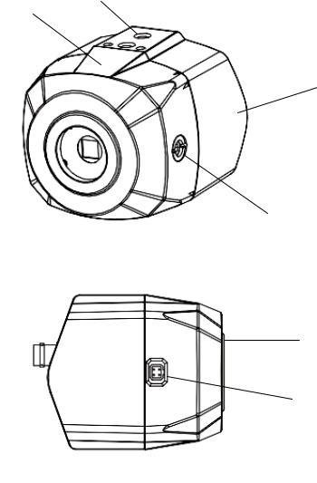
4. Part Names
Front view
Front Body
Mount Hole (Top and Bottom)
Rear Body
Back Focus Adjustment
Lens connector for auto iris lens
Dust Protection Cap
5

- Lens Connector for Auto-iris lens (DC Drive)
PIN 4 |
PIN 2 |
PIN No |
DC Iris |
1 |
Damp(-) |
2 |
Damp(+) |
3 |
Drive(+) |
4 |
GND |
PIN 3 |
PIN 1 |
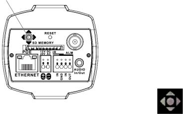
4.1Rear side view
|
|
|
|
IP Reset button
OSD menu Joystick Navigator
SD Memory Card Slot
RJ-45 Ethernet Port
Power Input Terminal
Alarm Input / Output Terminal
Audio Input / Output(3.5mm jack)Video Output Connector (BNC)
6
5.Installation and commissioning Instructions
•Make sure the power is removed before the installation.
•After all connections are finished properly, follow the order for applying power.
a)Plug the network cable into RJ-45 Ethernet Port at the rear panel.
If PoE is the unique power, there will be no need to connect Power terminal.
b)When DC12V or AC24V Local power is necessary, first connect the low voltage (DC12V or AC24V),
then plug the AC adapter to AC outlets to avoid an improper reset from power jitter and a damage from the surge voltage when no load.
When PoE and Local power are connected, Local power has priority.
5.1. Attaching the lens
•Remove the Dust Protection cap from the lens mount
•Screw the lens onto the camera firmly.
•Plug the lens plug into the lens connector
5.2. Setting the back focus
The proper back focus adjustment is essential for the motorized zoom lens to get the all time sharp focus when zooming in and out by the remote control.
For easier and better adjustment, this camera provides FOCUS ADJUST menu which prevents from the mistake of the focus adjustment.
With enabling FOCUS ADJUST menu, follow the procedure to get the best back focus adjustment.
1.Set the lens for the zoom position to WIDE and the focus position to INFINITE(∞)
2.Shoot the object departing from about 10Meters.
3.Adjust Back focus Adjustment with 3mm Hex L-wrench until the optimum focus is achieved.
4.Set the lens for zoom position to TELE and adjust the lens focus for best focus.
5.Set the lens for zoom position to WIDE again, check if the focus adjustment was the best. If not, re-adjust Back focus Adjustment slightly.
5.3. Installation
The camera has a 1/4” thread insert on its top and bottom side for mounting the camera to a tripod or the wall or ceiling with a corresponding mount.
7

5.4 Commissioning
•Connect PoE(IEEE Std. 802.3af) or the power supply to the power terminal on the rear panel of camera firstly
•Plug the power adaptor to the mains supply secondly
•Power indicator LED will be lit
•The camera is ready for operation
5.5Power Supply Connections
Camera can work with PoE(IEEE Std. 802.3af) and either 24VAC or 12VDC, dual voltage power. It does NOT require the polarity-matched connection for 12VDC supply. Primary and secondary grounds are completely isolated to avoid the possible ground-loop problems. Its excellently wide operating voltage range of 10.5V-30V for DC and 12-28.8V for AC gives an extra flexibility at the installation.
8
6. Setup Menu
6.1.1 Quick Network Setup
The network camera‘s default IP address is: 192.168.1.10.
Therefore, to access the camera for the first time, set the PC‘s address as
192.168.1.XX; for example: IP Address: 192.168.1.20 Subnet Mask: 255.255.255.0
•Enter the camera’s IP address in the URL bar of the Web browser window and hit “Enter.”
•Enter the default user name (root) and password (root) in the prompt request dialogue.
It is also possible to reset IP parameters to the original factory default settings by pressing the IP reset
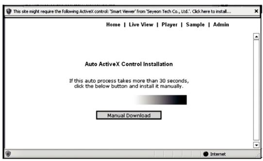
If the Information message doesn‘t come out due to the problems like network failure, you can start the manual installation.
9

Click the Install ActiveX Control, and the pop-up window will be displayed.
After the installation is successfully completed, Smart Viewer window will be displayed.
- Assigning an IP address
To assign an IP address to the camera proceeded as follows:
Click Network Configuration on the Network Configuration menu.
10
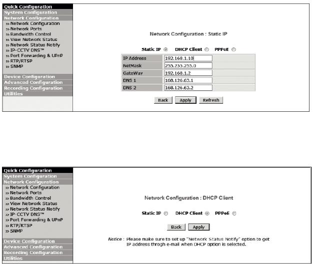
Depending on the service type, the network configuration can be in any of Static IP, DHCP Client, or PPPoE. You need to set up the network camera according to your network type.
For static IP, select static IP and input values for IP address, NetMask, Gateway,
DNS1, DNS2 and click apply for saving settings. After apply, program will ask closing web browser for updates, which will take 20~30 seconds.
11
For DHCP, DHCP server must exist in the network environment. Select DHCP Client from Network Configuration, click Apply.
PPPoE is used to connect IP products to PPPoE modem provided by ISP.
Since PPPoE needs verification, ID and password are necessary to access network. Type in ID and password.
12

- Administrator password
To change the password for the administrator, click Admin Password on System Configuration menu.
Default ID for admin account is fixed as “root” and not allowed to change.
In Old Password field, enter the current password. In both New Password and Confirm
Password fields, enter the same new password.
The password must be between 4 and 23 alphanumeric letters. Click Apply button to put it into effect.
Because you have replaced the password with a new one, the existing network connection made with old password now is lost.
You will have to reconnect using the new password.
13
- Accessing the setup menu
The setup menu can be accessed and controlled either by using the OSD control joy stick on the side of the camera and a service monitor or by entering the Admin menu in your web browser.
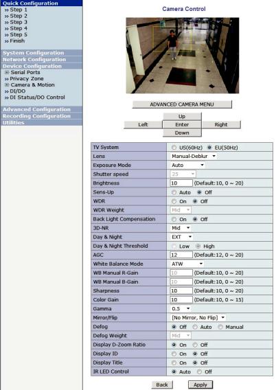
To control the menu, access to WEB> Device Configuration> Camera & Motion> Camera Control.
And for more detailed control for PRIVACY, MOTION, TITLE SET and POINTING ZOOM, please click ‘ADVANCED CAMERA MENU”.
14
6.1.2 Camera setup in the menu
Setup menu can be accessed and controlled by OSD control joy stick at the back of camera. Five commands are available with the joy stick.
Picture of OSD may differ by the models.
Joy stick
In the menu, use
SYMBOL descriptions for joystick operation;
-▲,▼, , denotes the directions of Joystick lever operation.
- denotes the long press down straightly for about 1.5 seconds.
D-Zoom Adjustment
(Only works when OSD Menu is not operating &
IP is not connected)
▲ D-Zoom In
▼ D-Zoom Out
▲,▼ to move menu, , to change the settings and press to select or enter.
The actual value of FACTORY DEFAULT may differ from this manual due to further technical improvements.
15
6.2 MAIN menu
Press ● to enter the setup menu for about 1 second.
|
MENU |
V3.01 |
|
|
|
|||
|
1. EXPOSURE |
|
|
DC |
|
|
||
|
2. LENS |
|
|
|
|
|||
|
3. FOCUS ADJ. |
|
|
|
|
|||
|
4. SCENE ENHANCE |
NORMAL |
|
|||||
|
|
|
|
|
||||
|
5. 3D-NR |
|
|
MID |
|
|||
|
6. DAY/NIGHT |
|
|
AUTO |
|
|||
|
7. PICT ADJUST |
|
|
|
|
|||
|
8. SPECIAL |
|
|
|
|
|
|
|
|
9. SYSTEM |
|
|
|
|
|
|
|
|
A. EXIT |
|
|
SAVE&EXIT |
|
|||
|
|
|
|
|
|
|
|
|
|
|
|
|
|
|
|
|
|
|
MAIN |
|
Default |
|
|
|
Descriptions |
|
|
|
|
|
|
|
|||
|
EXPOSURE |
|
|
|
Sets EXPOSURE MODE, BRIGHTNESS, SENS-UP and AGC. |
|||
|
|
|
|
See ‘6.3 EXPOSURE’ for detail. |
||||
|
|
|
|
|
||||
|
|
|
|
|
|
|||
|
LENS |
|
|
DC |
Sets Lens type and See ‘6.4 LENS’ for detail. |
|||
|
|
|
|
|
|
|||
|
FOCUS ADJ |
|
|
|
See ‘6.5 ZOOM/FOCUS’ for detail. |
|||
|
|
|
|
|
|
|||
|
|
|
|
|
NORMAL – Optimized for the normal indoor and outdoor in the good |
|||
|
|
|
|
|
lighting condition. |
|||
|
|
|
|
|
WDR – Improves the visibility for the high bright area and the dark area |
|||
|
|
|
|
|
by the double captures of image with LONG and SHORT exposures. |
|||
|
|
|
|
|
With WDR ON, the frame rate becomes half by the double captures. |
|||
|
|
|
|
|
WDR level can be selected from LOW, MID and HIGH. |
|||
|
SCENE |
|
|
|
Care should be taken to select this mode because video may lose its |
|||
|
|
NORMAL |
quality in some environments by the over compensation. |
|||||
|
ENHANCE |
|
D-WDR – Improves the visibility by compensating the video gain for the |
|||||
|
|
|
|
|||||
|
|
|
|
|
dark area. Noise can increase in the dark area accordingly. |
|||
|
|
|
|
|
BLC – Improves the visibility for the dark object by the bright back light. |
|||
|
|
|
|
|
Outside area of BLC window can over saturate. |
|||
|
|
|
|
|
BLC has a target window for compensation and its size and position |
|||
|
|
|
|
|
can be set by H-POS, V-POS, H-SIZE and V-SIZE. |
|||
|
|
|
|
|
HLC – Cuts out the highlight area with black mask and excludes it from |
|||
|
|
|
|
|
compensation. Lower HLC LEVEL cut out video from the lower level. |
|||
|
|
|
|
|
|
|||
|
|
|
|
|
Enables to set OFF, LOW, MID and HIGH. |
|||
|
|
|
|
|
3D-NR is a very sophisticated and powerful time-based noise reduction |
|||
|
3D-NR |
|
|
MID |
technology by monitoring the noise for the several video frames and defining |
|||
|
|
|
and eliminating them consecutively at low light. |
|||||
|
|
|
|
|
Higher setting reduces noise much more but results in losing the sharpness |
|||
|
|
|
|
|
and the tail effect or the motion blur for the fast moving target at low light. |
|||
16
|
|
Sets DAY / NIGHT to EXT, AUTO, COLOR and B/W. |
|
|
|
SMART IR can be set to reduce the saturation by the strong IR illumination |
|
|
|
in the night in any menu of EXT, AUTO and B/W(NIGHT) |
|
|
|
Setting SMART IR in any menu is identically applied to other menu. |
|
|
|
Zero(0) turns off SMART IR and High setting avoids the saturation strongly |
|
|
EXT |
but the corners will be darker accordingly. |
|
|
|
||
|
for |
EXT – DAY or NIGHT is determined by the built-in light photo sensor. |
|
|
IR LED |
||
|
Camera with IR LED must be set to EXT. |
||
|
|
||
DAY/NIGHT |
|
AUTO – Used when DAY or NIGHT is determined by light level through |
|
AUTO |
the lens and DAY from/to NIGHT is switched automatically by the |
||
|
|||
|
scene brightness. |
||
|
for |
||
|
D<-->N THRESHOLD, D<->N GAP, D<->N DELY and SMART IR can be |
||
|
No IR |
||
|
set in the menu.(See ‘6.7.2 DAY/NIGHT AUTO’ for detail.) |
||
|
LED |
||
|
When EXPOSURE>AGC is less than 10, DAY/NIGHT AUTO is disabled |
||
|
|
||
|
|
and forcibly switches to ___(DAY) to avoid the malfunction. |
|
|
|
EXT, B/W(NIGHT) and COLOR(DAY) is independent on AGC level. |
|
|
|
B/W(NIGHT) – Forcibly removes IR cut filter and switches to B/W |
|
|
|
regardless of light level. |
|
|
|
COLOR(DAY) – Forcibly DAY/NIGHT is disabled and outputs color video. |
|
PICT ADJUST |
|
Sets WHITE BAL, SHARPNESS, COLOR GAIN, GAMMA, SHADING. |
|
|
See ‘6.8 PICT ADJUST’ for detail. |
||
|
|
||
|
|
|
|
|
|
Sets MIRROR/FLIP, PRIVACY, MOTION, MOTION ZOOM, PIXEL DEFECT, |
|
SPECIAL |
|
TITLE SET, DISPLAY, DEFOG, POINTING ZOOM |
|
|
|
TV SYSTEM. See ‘6.8 SPECIAL’ for detail. |
|
SYSTEM |
|
Sets TV SYSTEM, RESOLUTION, COMM.SETUP, LANGUAGE and |
|
|
FACTORY DEFAULT. |
||
|
|
||
|
|
|
|
EXIT |
|
SAVE & EXIT – Exits the menu after saving the parameters. |
|
|
EXIT – Exits the menu without saving the menu. |
||
|
|
||
|
|
|
17
6.3 EXPOSURE
|
|
EXPOSURE |
|
|
|
SHUTTER |
|
AUTO |
|
|
BRIGHTNESS |
|:::::::|::::::| 10 |
|
|
|
SENS-UP |
|
OFF |
|
|
AGC |
|
|::::::::|:::::| 12 |
|
|
RETURN |
|
RET |
|
|
|
|
|
|
|
|
|
|
|
|
EXPOSURE |
Default |
|
Descriptions |
|
|
|
|
|
|
|
|
Can set EXPOSURE MODE to AUTO, MANUAL and Flickerless. |
|
|
|
|
AUTO – Optimizes the video level by controlling the iris and the shutter speed |
|
|
|
|
automatically. |
|
|
SHUTTER |
AUTO |
MANUAL – Iris and Shutter can be set to fix. |
|
|
Flickerless – Reduces the flicker in video when US(60Hz)/EU(50Hz) |
|||
|
|
|
||
|
|
|
mode is used in 50Hz/60Hz fluorescent lighting respectively. |
|
|
|
|
MANUAL and Flickerless modes disable SENS-UP and MOTION BLUR |
|
|
|
|
functions. |
|
|
|
|
|
|
|
BRIGHTNESS |
10 |
Adjusts the brightness of video(0~20). |
|
|
|
|
|
|
|
|
|
The brighter video can be obtained by increasing the exposure time in the |
|
|
|
|
night with SENS-UP. |
|
|
|
|
SENS-UP is the maximum integrations of frame by DSS(Digital Slow Shutter) |
|
|
SENS-UP |
AUTO |
in the low light. |
|
|
AUTO – SENS-UP(x2~x8) is enabled or disabled automatically by the scene |
|||
|
|
|
||
|
|
|
brightness. Higher SENS-UP can get the brighter video but the |
|
|
|
|
slower frame rates with motion blur and more white pixels. |
|
|
|
|
OFF – Disables SENS-UP. |
|
|
|
|
|
|
|
|
|
AGC(0~20) amplifies the video gain for brighter video but noise and white |
|
|
AGC |
12 |
pixel accordingly. |
|
|
|
|
AGC level less than 10 disables AUTO in DAY/NIGHT. |
|
|
|
|
|
|
18

6.4 LENS
|
DC |
MODE |
OUTDOOR |
RETURN |
RET |
|
MANUAL |
MODE |
DEBLUR |
RETURN |
RET |
Lens |
Default |
Descriptions |
|
|
|
|
|
|
|
Lens can be selected either DC or MANUAL lens. |
|
|
OURDOOR |
Lens MUST be set to DC for the best image when DC iris lens is installed. |
|
|
|
||
DC |
for |
DC or MANUALOUTDOOR, INDOOR, DEBLUR |
|
IR LED type |
|||
Select lens mode according to installation place. |
|||
|
|
||
or |
|
Select INDOOR or DEBLUR for indoor installation according to |
|
DEBLUR |
environment. |
||
|
|||
MANUAL |
DEBLUR enables to reduce the blur in a certain indoor environment. |
||
for |
|||
Noise or color rolling can increase. |
|||
|
No IR |
||
|
|
||
|
LED type |
Horizontal wave or bar may be seen when MANUAL is selected and the |
|
|
|
||
|
|
camera is working under florescent or similar lights. |
|
|
|
|
19
6.5 FOCUS ADJ.
FOCUS ADJ.
DN DWELL |
5s |
|||
POP ON FOCUS |
||||
OFF |
||||
RETURN |
||||
RET |
||||
|
|
|||
|
FOCUSING STATUS |
|
||
|
|
|
|
|
Usually cameras are installed in the day time and they often become OUT OF FOCUS at night time and IN FOCUS again at next day time.
This problem can occur at any cameras regardless of types or manufacturers.
FOCUS ADJ. menu is the unique and patented feature that prevents from the wrong focus and helps the EXACT NEEDLE focus by simulating DAY & NIGHT conditions.
Set zoom first and adjust focus to get NEEDLE FOCUS while switching AT DAY AND NIGHT
FOCUS ADJ. |
Default |
Descriptions |
|
|
ICR switcher switches DAY & NIGHT at the interval of D/N DWELL |
|
DN DWELL |
5s |
to help the EXACT NIDDLE focus at DAY and NIGHT mode. |
|
|
|
Further simulations are performed internally during switching. |
|
|
|
|
|
POP ON FOCUS |
OFF |
ON zooms in the center of picture at 2X for better focusing. |
|
|
|
|
|
FOCUSING |
|
Shows how exactly focus is set. |
|
ON |
When blue bar doesn’t show up, try the lens focus to NEAR and FAR. |
||
STATUS |
|||
|
|
The maximum blue bar indicates the best focusing position. |
20

6.7 PICT ADJUST
PICTURE
WHITE BAL |
ATW |
SHARPNESS |
|:::::::|::::::| 10 |
COLOR GAIN |
|:::::::|::::::| 10 |
GAMMA |
0.50 |
SHADING |
OFF |
RETURN |
RET |
PICTURE |
Default |
Descriptions |
|
|
|
|
|
|
|
ATW, ATWext, ONE PUSH and MANUAL are available for the white balance |
|
|
|
modes. |
|
|
|
ATW – White balance is continuously working along with the color |
|
|
|
temperature changes in the range of 2,000K~8,500K. |
|
WHITE BAL |
ATW |
ATWext – White balance is continuously working along with the color |
|
temperature changes in the range of 1,800K~11,000K. |
|||
|
|
||
|
|
ONE PUSH- White balance works only during ● is pressed. |
|
|
|
MANUAL – White balance is fixed to the settings by R_GAIN and |
|
|
|
B-GAIN. This mode can be used only when the color temperature |
|
|
|
does not vary. |
|
|
|
|
|
SHARPNESS |
10 |
Adjusts the sharpness of video(0~20). |
|
|
|
|
|
COLOR GAIN |
10 |
Adjusts the color level of video(0~20). |
|
|
|
|
|
GAMMA |
0.50 |
Adjusts the gamma of video. |
|
|
|
|
|
SHADING |
OFF |
ON enables to compensate the shade caused by wide lens setting |
|
|
|
|
21
6.8 SPECIAL
|
|
PICTURE |
|
|
|
|
MIRROR/FLIP |
OFF |
|
||
|
PRIVACY |
|
|
OFF |
|
|
MOTION |
|
|
OFF |
|
|
PIXEL DEFECT |
OFF |
|
||
|
TITLE SET |
|
|
|
|
|
DISPLAY |
|
|
|
|
|
DEFOG |
|
|
OFF |
|
|
POINTING ZOOM |
OFF |
|
||
|
RETURN |
|
|
RET |
|
|
|
|
|
|
|
|
|
|
|
|
|
|
SPECIAL |
Default |
|
|
Descriptions |
|
|
|
|
|
|
|
|
|
|
Reverses the video left and right and/or up and down by MIRROR/FLIP. |
|
|
|
|
|
OFF - Normal display without mirroring or flipping |
|
|
|
|
|
Hor. – Video is reversed left and right. |
|
|
MIRROR/FLIP |
OFF |
|
Ver. – Video is reversed upside down. |
|
|
|
HV – Video is reversed left and right and upside down. |
|||
|
|
|
|
||
|
|
|
|
When the video is reversed by Ver. or HV, then the joystick directions are |
|
|
|
|
|
reversed accordingly. This feature is very useful when a camera in installed in |
|
|
|
|
|
upside dawn. |
|
|
|
|
|
10 Privacy zones which can be enabled individually by ZON DISP are available |
|
|
|
|
|
to mask the video. |
|
|
|
|
|
ZONE NUMBER – Set a number to select a privacy zone from 1~10. |
|
|
PRIVACY |
OFF |
|
ZONE DISP – ON enables a relevant privacy zone. |
|
|
|
|
|
H-POS, V-POS, H-SIZE and V-SIZE – Adjust the size and position of zone. |
|
|
|
|
|
COLOR – Select the color used for masking the zone form eight colors(1~8). |
|
|
|
|
|
TRANSPARENCY – Enables to set OFF, 50%, 75%, 100%. |
|
|
|
|
|
Defines the transparency for the mask zone. |
|
|
|
|
|
MOTION can detect the changes in the motion window and displays the results |
|
|
|
|
|
in blocks and/or a text message. |
|
|
|
|
|
SENSITIVITY – Adjusts the detection sensitivity for motion. |
|
|
|
|
|
High value increases the sensitivity to detect the small motion easily. |
|
|
|
|
|
Too low sensitivity will cause the erratic detection by the tree leaves |
|
|
|
|
|
or the light level changes. |
|
|
|
|
|
H-POS,V-POS, H-SIZE and V-SIZE - Adjust the size and position of |
|
|
|
|
|
the detection window. |
|
|
MOTION |
OFF |
|
BLOCK DISP – ON enables to display the blocks for the detected area. |
|
|
|
|
|
MOTION OSD – ON enables to display a text message, ‘MOTION’, |
|
|
|
|
|
SMART MOTION ZOOM – ON activates Automatic Zoom IN/OUT when motion |
|
|
|
|
|
is detected. |
|
|
|
|
|
Area to be zoomed in by SMART MOTION ZOOM can be set at SPECIAL> |
|
|
|
|
|
MOTION> SMART MOTION ZOOM. |
|
|
|
|
|
Adjusting , (Joystick) varies the viewing angle to be zoomed when the |
|
|
|
|
|
motion occurs. See ‘6.8.1 SMART MOTION ZOOM’ for detail. |
|
|
|
|
|
STAY ZOOMING – Sets the duration time for zooming by Motion. |
|
22
|
|
Detects and compensates the white pixels which becomes defective. |
|
|
|
Once CALIBRATE is selected, the pixel calibration is initiated with lens closed |
|
|
|
and can’t cancel. |
|
|
|
THRESHOLD – Defines the level of detection and low value detects more |
|
PIXEL DEFECT |
OFF |
pixels. Be sure to set the value so that the pixels are uniformly blinking |
|
|
|
over the entire screen. Too low value will get the bad results because |
|
|
|
too many pixels are detected as the bad pixels and the maximum |
|
|
|
number of pixels for compensation will be filled by the upper area. |
|
|
|
EXECUTE - Long pressing will execute the pixel calibration for the |
|
|
|
detected pixels. Menu will exit automatically after compensation. |
|
|
|
|
|
|
|
Camera title(name) can be set and edited up to 15 alpha numeric and symbolic |
|
|
|
characters from ASCII codes(ENGLISH only). |
|
|
|
▲,▼, , moves the cursor to choose a character and |
|
|
|
● selects it. |
|
TITLE SET |
- |
The selected characters are added and displayed on the top left |
|
Corner and the cursor moves right automatically for next input. |
|||
|
|
||
|
|
SP - Space is inserted when pressed ●. |
|
|
|
BS – Cursor moves back when pressed ●. |
|
|
|
CLR – Clears all the characters on input line when pressed ●. |
|
|
|
POS – To be able to set the title position by ▲,▼, , and ●. |
|
|
|
|
|
|
|
Enables or disables to display the OSD. |
|
|
|
ID – ON enables to display the camera ID defined by SYSTEM>COMM. |
|
|
|
SETUP>CAM ID. |
|
DISPLAY |
- |
TITLE – ON enables to display the camera title(name) set by SPECIAL> |
|
|
|
TITLE SET. |
|
|
|
D-ZOOM RATIO – ON enables to display the zoom ratio on the bottom right |
|
|
|
corner. DZx.x will display by multiplying the actual digital zoom ratio. |
|
|
|
|
|
|
|
AUTO – Enhance the foggy video automatically according to |
|
|
|
status of scene |
|
DEFOG |
OFF |
MANUAL – Sets to enhance the foggy video manually regardless of |
|
status of scene |
|||
|
|
||
|
|
LEVEL – LOW, MID, HIGH |
|
|
|
Video quality can be less in normal environments. |
|
|
|
|
|
|
|
ON enables to set off-centered location to be the center of zoom |
|
POINTING |
OFF |
H-POINTER, V-POINTER- Able to set the location of zoom center |
|
ZOOM |
D-Zoom is available DZ X1.0~ X8.0. |
||
|
|||
|
|
See ‘6.8.2 POINTING ZOOM’ for detail. |
23

6.8.1 SMART MOTION ZOOM
SMART MOTION ZOOM crops and enlarges the certain area defined by a yellow window to the full sized image when the motion is detected in the black window.
SMART MOTION ZOOM window can be re-sized by adjusting D-ZOOM RATIO and moved by H-POINTER and V-POINTER.
UNLIKE the conventional zoom which can zoom in/out the center area of image only, by the flexible zoom location and area, SMART MOTION ZOOM differentiate its usefulness from others.
That is, a conventional camera installed on the corner of ceiling can zoom the center of the floor in a room and result in losing the image of door on the side wall.
However, SMART MOTION ZOOM can be set to see the door side and zoom in that area without missing the IMPORTANT security point.
SMART MOTION ZOOM
|
H-POINTER |
10 |
|
|
V-POINTER |
10 |
|
|
D-ZOOM RATIO |
MZ2.0 |
|
|
RETURN |
RET |
|
|
|
|
|
|
|
|
|
SMART |
Default |
Descriptions |
|
MOTION ZOOM |
|||
|
|
||
|
|
|
|
H-POINTER |
10 |
Moves MOTION ZOOM area(Yellow window) horizontally. |
|
|
|
|
|
V-POINTER |
10 |
Moves MOTION ZOOM area(Yellow window) vertically. |
|
|
|
|
|
D-ZOOM |
MZ2.0 |
Sets the area size to be zoomed when the motion occurs in the black window. |
|
RATIO |
|||
|
|
||
|
|
|
24

6.8.2 POINTING ZOOM
This camera has a very useful and powerful feature, POINTING ZOOM, which can zoom in/out any area.
UNLIKE the conventional zoom which can zoom in/out the center area of image only, by the flexible zoom location and area, POINTING ZOOM differentiate its usefulness from others.
That is, a conventional camera installed on the corner of ceiling can zoom the center of the floor in a room and result in losing the image of door on the side wall.
However, POINTING ZOOM can be set to see the door side and zoom in that area without missing the IMPORTANT security point.
POINTING ZOOM can be activated by the joystick operations of ▲ for zoom in and▼ for zoom out, while SMART MOTION ZOOM is activated by the result of motion detection in the defined area.
POINTING ZOOM
H-POINTER |
10 |
|
V-POINTER |
10 |
|
RETURN |
|
RET |
|
|
|
POINTING |
Default |
Descriptions |
|
ZOOM |
|||
|
|
||
|
|
|
|
H-POINTER |
10 |
Sets the horizontal location of area to be zoomed by POINTING ZOOM. |
|
|
|
|
|
V-POINTER |
10 |
Sets the vertical location of area to be zoomed by POINTING ZOOM. |
|
|
|
|
25

6.9 SYSTEM
SYSTEM
TV SYSTEM |
US(NTSC) |
|
RESOLUTION |
1080P |
|
COMM. SETUP |
ENG |
|
LANGUAGE |
||
|
||
FACTORY DEFAULT |
NO |
|
RETURN |
RET |
|
|
SYSTEM |
Default |
Descriptions |
|
|
|
|
|
|
US |
Selects HDTV standards for US(NTSC) or EU(PAL). |
|
TV SYSTEM |
or |
||
By this selection, 2nd analog video output switches to NTSC or PAL accordingly. |
|||
|
EU |
|
|
|
|
1080P and 720P are available. |
|
RESOLUTION |
1080P |
1080P outputs the frame rate at 30P/25P. 720P outputs the frame rate at |
|
60P/50P but the image refresh rate is 30P/25P. |
|||
|
|
||
|
|
720P video is scaled down from 1080P and the field of view has no loss. |
|
|
|
|
|
|
|
COMM. SETUP defines the CAM ID, BAUD RATE and PROTOCOL. |
|
COMM. |
|
Data length, stop bit and parity are fixed to 8bit, 1stop bit and no parity bit. |
|
- |
CAM ID – Assigns the camera ID from 1~255 for the comm. address. |
||
SET UP |
|||
|
BAUD RATE – Selects the baud rate from 2400~115200. |
||
|
|
||
|
|
PROTOCOL – Selects the comm. Protocolfrom PELCO-D/P or VISCA. |
|
|
|
|
|
|
|
Seven languages are available for ENGLISH, JAPANESE, GERMAN, |
|
LANGUAGE |
ENG |
FRENCH, ITALIAN, SPANISH and POLISH. |
|
|
|
When changing LANGUAGE, select language and press to load. |
|
|
|
|
|
FACTORY |
NO |
RECALL roads and saves the factory defaults |
|
DEFAULT |
|||
|
|
26
7. Specifications
|
PXC-2080CS |
|
|
Imaging Sensor |
Sony Exmor 1/2.9" Progressive Scan CMOS Sensor |
|
|
Effective Pixels |
1,936(H) x 1,097(V) |
|
|
Min. Illumination |
0.0005 Lux @ (AGC MAX, DSS x2) |
|
|
Output Video Resolution |
1,920x1,080 30p/25p |
|
|
TV system |
EU(50Hz)(switchable to US(60Hz)) |
|
|
Sync. System |
Internal |
|
|
Format |
16:9 Video format for most popular commercial HDTV monitors |
|
|
Video Output |
Ethernet thru LAN Port for RJ45 & CVBS thru BNC |
|
|
Video Sub-out |
NTSC/PAL standard, 1Vpp @75Ω terminated |
|
|
S/N Ratio |
More than 50dB (AGC OFF) |
|
|
Lens Type |
CS Mount Lens Support ( C-Mount adaptor option) |
|
|
LEDs |
NON IR LEDs |
|
|
Day & Night |
TDN by dual filter switcher, AUTO, COLOR, B/W, EXT |
|
|
Exposure |
AUTO / MANUAL / Flickerless |
|
|
Flip |
OFF/ H/ V/ HV FLIP |
|
|
White balance |
ATW, One Push, MANUAL |
|
|
WDR |
True WDR by dual scan images in two frames at 15fps. |
|
|
Special Features |
Intelligent Focus Indicator on Screen, |
SMART MOTION ZOOM(Digital Zoom IN/OUT when motion is detected), |
|
|
POINTING ZOOM(Enables the flexible zooming at any area) |
|
|
Functions |
NORMAL, WDR, D-WDR, 3DNR, SMART IR, MOTION DETECT, |
PRIVACY MASK, BLC/HLC, Digital ZOOM, Anti Fog, Sense-up(x8) |
|
|
|
Language |
English, German, French, Italian, Spanish, Polish, Japanese |
|
|
IR Input |
Low active TTL input from External IR illuminator to avoid the undesirable |
ICR switch |
|
Operating Temperature |
-10ºC ~ +50 ºC (Humidity : 30%RH ~ 80%RH) |
|
|
Housing |
Solid Aluminum Cast |
|
|
27

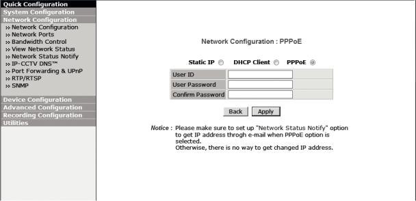
External Dimension |
74mm x 72mm x 89mm, 300g |
|
|
Power Source |
PoE(IEEE Std. 802.3af ), 24VAC/12VDC DUAL POWER, 500mA |
|
|
|
Circuit protection against faulty connection |
|
|
|
Isolated power supply against ground loop problem |
|
|
IP SPECIFICATION |
|
|
|
Video Encoding |
H.264 / MJPEG dual streaming |
|
|
Protocol |
HTTP, TCP/UDP/IP, ARP, ICMP, RTP/RTSP, multicast, Telnet, ftp, PPPoE, |
SMTP(e-mail), DHCP, NTP, uPNP, etc, ONVIF, PSIA support |
|
Transmission Control |
VBR, CBR ( 32K ~ 12M bps ) |
|
|
CMS |
Bundled with Full featured 16 channels PC NVR. |
|
32/64 channels available(Option) |
IP Installation & |
Configuration: installation wizard, HTTP, telnet and console, Upgrade |
maintenance |
firmware: HTTP, telnet+ftp |
|
|
Connectivity |
Max. 16 simultaneous user connection |
|
|
SD memory card |
Slot for Standard SD memory card up to 32GB |
|
|
Audio & Alarm |
Audio & Alarm input /output |
|
|
PoE |
IEEE Std. 802.3af |
● Design and specifications are subject to change for product improvements without prior notice.
28
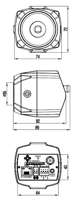
8. Dimensional Drawings
(Unit: mm)
29
 Loading...