

Endress+Hauser Proline Promass 80A, Proline Promass 83A Technical Information
Technical Information
Proline Promass 80A, 83A
Coriolis Mass Flow Measuring System
The single-tube system for highly accurate measurement of
very small flows
Application
The Coriolis measuring principle operates independently
of the physical fluid properties, such as viscosity and
density.
• Suitable for continuous measurement, filling and
dosing of very small flows.
• Extremely accurate measurement of liquids and
gases such as emulsions, additives, flavouring,
insulin, gases for high pressure and low pressure
• Fluid temperatures up to +200 °C (+392 °F)
• Process pressures up to 400 bar (5800 psi)
Approvals for hazardous area:
• ATEX, FM, CSA, TIIS, IECEx, NEPSI
Approvals in the food industry/hygiene sector:
• 3A, FDA, EHEDG
Connection to process control system:
• HART, PROFIBUS DP/PA, FOUNDATION Fieldbus,
MODBUS
Relevant safety aspects:
• Pressure Equipment Directive, SIL-2
• Purge connection or rupture disk (optional)
Your benefits
The Promass measuring devices make it possible to
simultaneously record several process variables (mass/
density/temperature) for various process conditions
during measuring operation.
The Proline transmitter concept comprises:
• Modular device and operating concept resulting in a
higher degree of efficiency
• Software options for batching and concentration
measurement for extended range of application
• Diagnostic ability and data back-up for increased
process quality
The Promass sensors, tried and tested in over
100000 applications, offer:
• Multivariable flow measurement in compact design
• Insensitivity to vibrations thanks to balanced singletube measuring system
• Immune from external piping forces due to robust
design
• Easy installation without taking inlet and outlet runs
into consideration
TI054D/06/en/10.09
71104043

Table of contents
Proline Promass 80A, 83A
Function and system design. . . . . . . . . . . . . . . . . . . . . 3
Measuring principle . . . . . . . . . . . . . . . . . . . . . . . . . . . . . . . . . . . 3
Measuring system . . . . . . . . . . . . . . . . . . . . . . . . . . . . . . . . . . . . . 4
Input . . . . . . . . . . . . . . . . . . . . . . . . . . . . . . . . . . . . . . 6
Measured variable . . . . . . . . . . . . . . . . . . . . . . . . . . . . . . . . . . . . 6
Measuring range . . . . . . . . . . . . . . . . . . . . . . . . . . . . . . . . . . . . . . 6
Operable flow range . . . . . . . . . . . . . . . . . . . . . . . . . . . . . . . . . . . 6
Input signal . . . . . . . . . . . . . . . . . . . . . . . . . . . . . . . . . . . . . . . . . 6
Output . . . . . . . . . . . . . . . . . . . . . . . . . . . . . . . . . . . . . 7
Output signal . . . . . . . . . . . . . . . . . . . . . . . . . . . . . . . . . . . . . . . . 7
Signal on alarm . . . . . . . . . . . . . . . . . . . . . . . . . . . . . . . . . . . . . . 9
Load . . . . . . . . . . . . . . . . . . . . . . . . . . . . . . . . . . . . . . . . . . . . . . 9
Low flow cutoff . . . . . . . . . . . . . . . . . . . . . . . . . . . . . . . . . . . . . . 9
Galvanic isolation . . . . . . . . . . . . . . . . . . . . . . . . . . . . . . . . . . . . . 9
Switching output . . . . . . . . . . . . . . . . . . . . . . . . . . . . . . . . . . . . . 9
Power supply . . . . . . . . . . . . . . . . . . . . . . . . . . . . . . . 10
Electrical connection Measuring unit . . . . . . . . . . . . . . . . . . . . . 10
Electrical connection, terminal assignment . . . . . . . . . . . . . . . . . 11
Electrical connection Remote version . . . . . . . . . . . . . . . . . . . . . 12
Supply voltage . . . . . . . . . . . . . . . . . . . . . . . . . . . . . . . . . . . . . . 12
Cable entries . . . . . . . . . . . . . . . . . . . . . . . . . . . . . . . . . . . . . . . 13
Remote version cable specifications . . . . . . . . . . . . . . . . . . . . . . . 13
Power consumption . . . . . . . . . . . . . . . . . . . . . . . . . . . . . . . . . . 13
Power supply failure . . . . . . . . . . . . . . . . . . . . . . . . . . . . . . . . . . 13
Potential equalisation . . . . . . . . . . . . . . . . . . . . . . . . . . . . . . . . . 13
Performance characteristics. . . . . . . . . . . . . . . . . . . . 14
Reference operating conditions . . . . . . . . . . . . . . . . . . . . . . . . . . 14
Maximum measured error . . . . . . . . . . . . . . . . . . . . . . . . . . . . . 14
Repeatability . . . . . . . . . . . . . . . . . . . . . . . . . . . . . . . . . . . . . . . . 15
Influence of medium temperature . . . . . . . . . . . . . . . . . . . . . . . . 16
Influence of medium pressure . . . . . . . . . . . . . . . . . . . . . . . . . . . 16
Design fundamentals . . . . . . . . . . . . . . . . . . . . . . . . . . . . . . . . . 16
Operating conditions: Process . . . . . . . . . . . . . . . . . . 20
Medium temperature range . . . . . . . . . . . . . . . . . . . . . . . . . . . . 20
Medium pressure range (nominal pressure) . . . . . . . . . . . . . . . . 20
Rupture disk (optional) . . . . . . . . . . . . . . . . . . . . . . . . . . . . . . . . 21
Limiting flow . . . . . . . . . . . . . . . . . . . . . . . . . . . . . . . . . . . . . . . 21
Pressure loss in SI units . . . . . . . . . . . . . . . . . . . . . . . . . . . . . . . 22
Mechanical construction . . . . . . . . . . . . . . . . . . . . . . 23
Design / dimensions . . . . . . . . . . . . . . . . . . . . . . . . . . . . . . . . . 23
Weight . . . . . . . . . . . . . . . . . . . . . . . . . . . . . . . . . . . . . . . . . . . 36
Material . . . . . . . . . . . . . . . . . . . . . . . . . . . . . . . . . . . . . . . . . . . 37
Material load curves . . . . . . . . . . . . . . . . . . . . . . . . . . . . . . . . . . 38
Process connections . . . . . . . . . . . . . . . . . . . . . . . . . . . . . . . . . . 39
Human interface . . . . . . . . . . . . . . . . . . . . . . . . . . . . 40
Display elements . . . . . . . . . . . . . . . . . . . . . . . . . . . . . . . . . . . . 40
Operating elements . . . . . . . . . . . . . . . . . . . . . . . . . . . . . . . . . . 40
Language group . . . . . . . . . . . . . . . . . . . . . . . . . . . . . . . . . . . . . 40
Remote operation . . . . . . . . . . . . . . . . . . . . . . . . . . . . . . . . . . . . 40
Certificates and approvals . . . . . . . . . . . . . . . . . . . . . 41
CE mark . . . . . . . . . . . . . . . . . . . . . . . . . . . . . . . . . . . . . . . . . . 41
C-Tick mark . . . . . . . . . . . . . . . . . . . . . . . . . . . . . . . . . . . . . . . 41
Ex approval . . . . . . . . . . . . . . . . . . . . . . . . . . . . . . . . . . . . . . . . 41
Sanitary compatibility . . . . . . . . . . . . . . . . . . . . . . . . . . . . . . . . . 41
FOUNDATION Fieldbus certification . . . . . . . . . . . . . . . . . . . . . 41
PROFIBUS DP/PA certification . . . . . . . . . . . . . . . . . . . . . . . . . 41
MODBUS certification . . . . . . . . . . . . . . . . . . . . . . . . . . . . . . . . 41
Other standards and guidelines . . . . . . . . . . . . . . . . . . . . . . . . . . 41
Pressure measuring device approval . . . . . . . . . . . . . . . . . . . . . . 41
Functional safety . . . . . . . . . . . . . . . . . . . . . . . . . . . . . . . . . . . . 42
Ordering Information. . . . . . . . . . . . . . . . . . . . . . . . . 42
Accessories . . . . . . . . . . . . . . . . . . . . . . . . . . . . . . . . 42
Operating conditions: Installation . . . . . . . . . . . . . . . 17
Installation instructions . . . . . . . . . . . . . . . . . . . . . . . . . . . . . . . . 17
Inlet and outlet run . . . . . . . . . . . . . . . . . . . . . . . . . . . . . . . . . . 19
Length of connecting cable . . . . . . . . . . . . . . . . . . . . . . . . . . . . . 19
System pressure . . . . . . . . . . . . . . . . . . . . . . . . . . . . . . . . . . . . . 19
Documentation . . . . . . . . . . . . . . . . . . . . . . . . . . . . . 42
Registered trademarks . . . . . . . . . . . . . . . . . . . . . . . . 43
Operating conditions: Environment. . . . . . . . . . . . . . 20
Ambient temperature range . . . . . . . . . . . . . . . . . . . . . . . . . . . . 20
Storage temperature . . . . . . . . . . . . . . . . . . . . . . . . . . . . . . . . . . 20
Ambient class . . . . . . . . . . . . . . . . . . . . . . . . . . . . . . . . . . . . . . . 20
Degree of protection . . . . . . . . . . . . . . . . . . . . . . . . . . . . . . . . . . 20
Shock resistance . . . . . . . . . . . . . . . . . . . . . . . . . . . . . . . . . . . . . 20
Vibration resistance . . . . . . . . . . . . . . . . . . . . . . . . . . . . . . . . . . 20
CIP cleaning . . . . . . . . . . . . . . . . . . . . . . . . . . . . . . . . . . . . . . . . 20
SIP cleaning . . . . . . . . . . . . . . . . . . . . . . . . . . . . . . . . . . . . . . . . 20
Electromagnetic compatibility (EMC) . . . . . . . . . . . . . . . . . . . . . 20
2 Endress+Hauser
Proline Promass 80A, 83A
Function and system design
Measuring principle The measuring principle is based on the controlled generation of Coriolis forces.
These forces are always present when both translational and rotational movements are superimposed.
FC = 2 · Δm (v · ω)
= Coriolis force
F
C
Δm = moving mass
ω = rotational velocity
v = radial velocity in rotating or oscillating system
The amplitude of the Coriolis force depends on the moving mass Δm, its velocity v in the system,
and thus on the mass flow. Instead of a constant angular velocity ω, the Promass sensor uses oscillation.
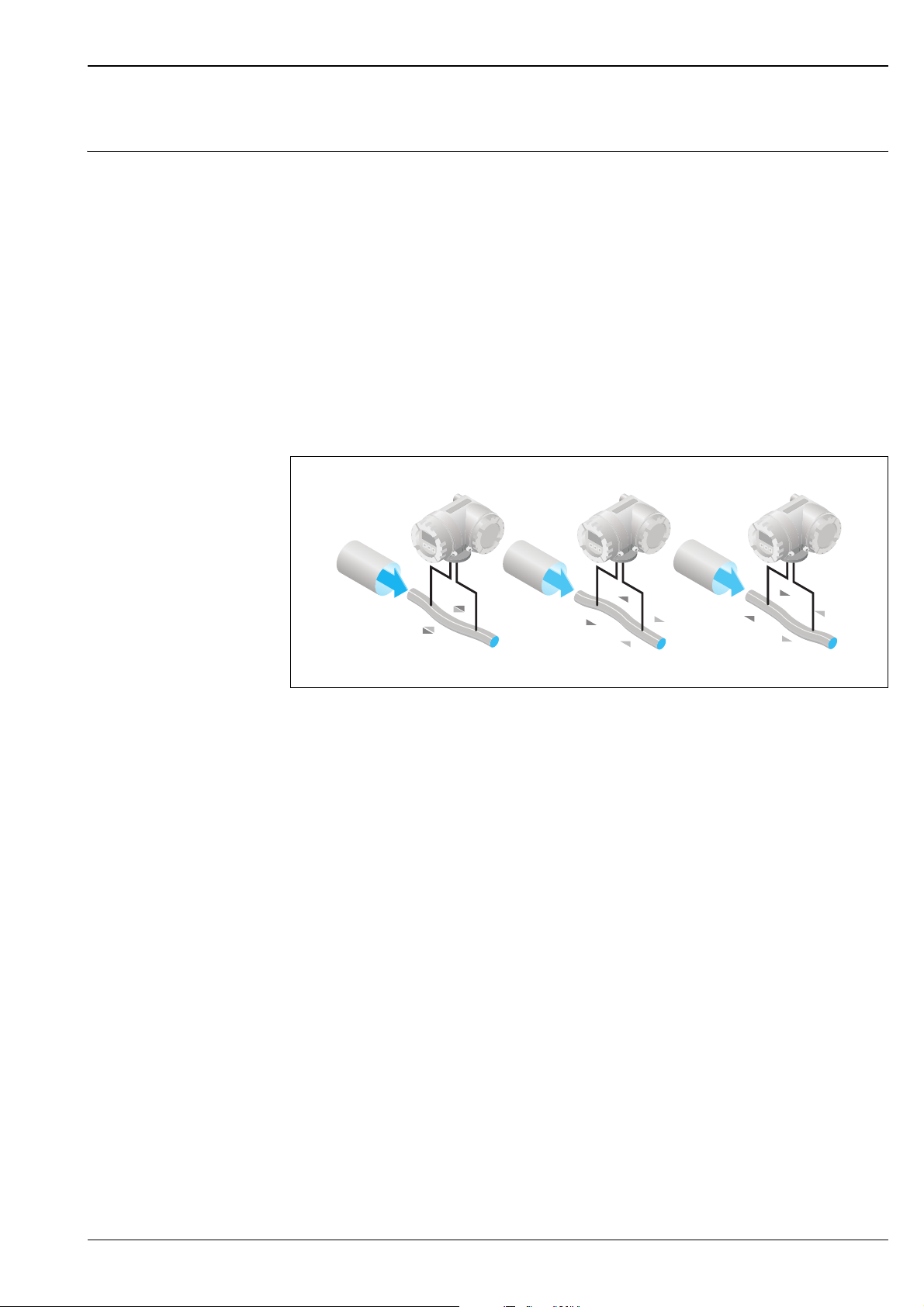
The measuring tube, through which the medium flows, oscillates. The Coriolis forces produced at the
measuring tube cause a phase shift in the tube oscillations (see illustration):
• At zero flow, i.e. when the fluid is at a standstill, the oscillation registered at points A and B is in phase,
i.e. there is no phase difference (1).
• Mass flow causes deceleration of the oscillation at the inlet of the tubes (2) and acceleration at the outlet (3).
A
B
A
B
A
B
12 3
a0003383
The phase difference (A-B) increases with increasing mass flow. Electrodynamic sensors register the tube
oscillations at the inlet and outlet.
Compared to two-tube systems, other constructive solutions are required for the system balance for single-tube
systems. For this purpose, Promass A has an internal reference mass.
The measuring principle operates independently of temperature, pressure, viscosity, conductivity and flow
profile.
Density measurement
The measuring tube is continuously excited at its resonance frequency. A change in the mass and thus the
density of the oscillating system (comprising measuring tube and fluid) results in a corresponding, automatic
adjustment in the oscillation frequency. Resonance frequency is thus a function of fluid density.
The microprocessor utilises this relationship to obtain a density signal.
Temperature measurement
The temperature of the measuring tube is determined in order to calculate the compensation factor due to
temperature effects. This signal corresponds to the process temperature and is also available as an output.
Endress+Hauser 3
Proline Promass 80A, 83A
Esc
E
-
+
Measuring system The measuring system consists of a transmitter and a sensor. Two versions are available:
• Compact version: transmitter and sensor form a mechanical unit.
• Remote version: transmitter and sensor are mounted physically separate from one another.
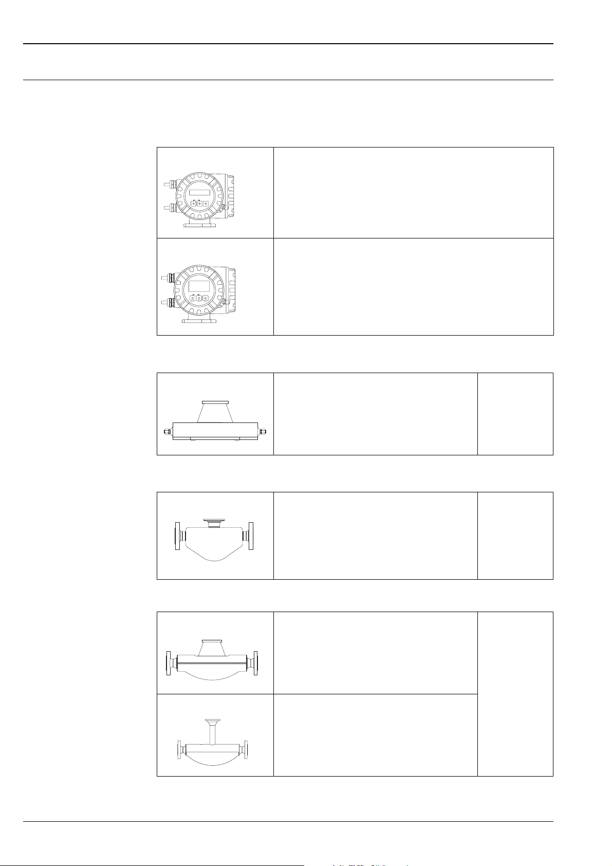
Transmitter
Promass 80
Promass 83
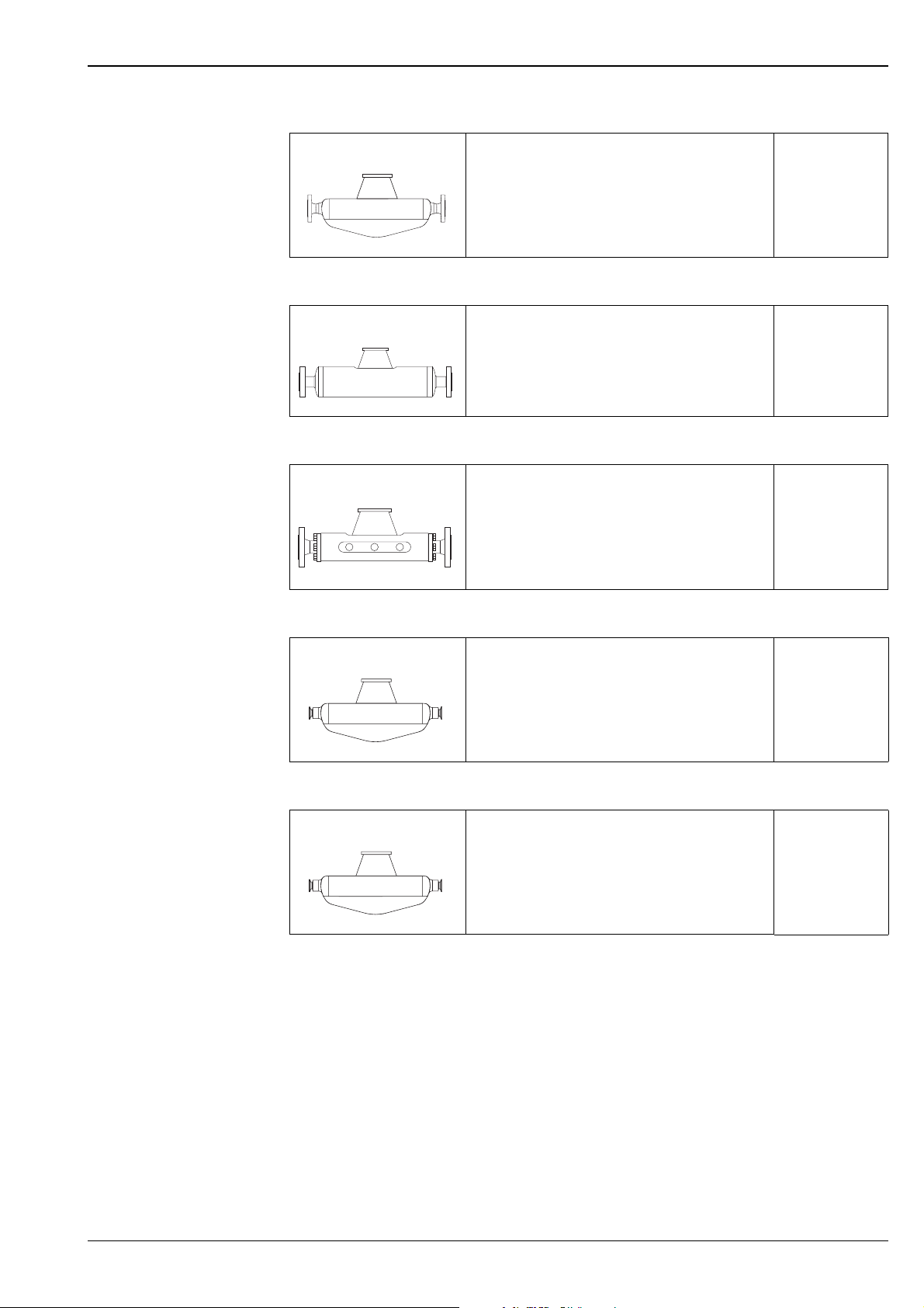
Sensor
A
• Two-line liquid-crystal display
• Configuration also using key operation
a0003671
• Four-line liquid-crystal display
• Operation with "Touch control"
• Application-specific Quick Setup
• Mass flow, volume flow, density and temperature measurement as well as
Esc
–
+
E
a0003672
calculated variables (e.g. fluid concentrations)
• Single-tube system for highly accurate measurement of
very small flows
Documentation
No. TI054D
• Nominal diameters DN 1 to 4 (1/24" to 1/8")
• Material: Stainless steel EN 1.4539/ASTM 904L,
EN 1.4404/ASTM 316L (process connection),
Alloy C-22 DIN 2.4602
a0003679
Other sensors can be found in the separate documentation
E
F
F (High-temperature)
• General purpose sensor, ideal replacement for volumetric
flowmeters.
• Nominal diameters DN DN 8 to 50 (3/8" to 2")
• Material: Stainless steel EN 1.4539/ASTM 904L,
EN 1.4404/ASTM 316L
a0002271
• Universal sensor for fluid temperatures
up to +200 °C (+392 °F).
• Nominal diameters DN 8 to 250 (3/8" to 10").
• Material: Stainless steel EN 1.4539/ASTM 904L,
EN 1.4404/ASTM 316L, Alloy C-22 DIN 2.4602
a0003673
• Universal high-temperature sensor for fluid temperatures
up to +350 °C (+662 °F).
• Nominal diameters DN 25, 50, 80 (1", 2", 3")
• Material: Alloy C-22, DIN 2.4602,
EN 1.4404/ASTM 316L
a0003675
Documentation No.
TI061D
Documentation No.
TI101D
4 Endress+Hauser
Proline Promass 80A, 83A
H
• Single bent tube. Low pressure loss and chemically
resistant material
Documentation No.
TI074D
• Nominal diameters DN 8 to 50 (3/8" to 2")
• Material: Zirconium 702/R 60702, Tantalium 2.5W
a0003677
I
• Straight single-tube instrument. Minimal shear stress on
fluid, hygienic design, low pressure loss
Documentation No.
TI075D
• Nominal diameters DN 8 to 80 (3/8" to 3")
• Material: Titanium, Ti Grade 2, Ti Grade 9
a0003678
M
• Robust sensor for extreme process pressures, high
requirements for the secondary containment and fluid
Documentation No.
TI102D
temperatures up to +150 °C (+302 °F)
• Nominal diameters DN 8 to 80 (3/8" to 3")
• Material: Titanium, Ti Grade 2, Ti Grade 9
a0003676
P
• Single bent tube, minimal shear stress on fluid.
Hygienic design with documents for Life Science
Documentation No.
TI078D
Industries applications, low pressure loss, for fluid
temperatures up to +200 °C (+392 °F).
• Nominal diameters DN 8 to 50 (3/8" to 2")
• Material: Stainless steel EN 1.4435/ASTM 316L
a0006828
S
• Single bent tube.
Hygienic design, low pressure loss, for fluid temperatures
Documentation No.
TI076D
up to +150 °C (+302 °F)
• Nominal diameters DN 8 to 50 (3/8" to 2")
• Material: Stainless steel, EN 1.4539/ASTM 904L,
EN 1.4435/ASTM 316L
a0006828
Endress+Hauser 5

Proline Promass 80A, 83A
Input
Measured variable • Mass flow (proportional to the phase difference between two sensors mounted on the measuring tube to
register a phase shift in the oscillation)
• Fluid density (proportional to resonance frequency of the measuring tube)
• Fluid temperature (measured with temperature sensors)
Measuring range Measuring ranges for liquids
Nominal Diameter Range for full scale values (liquids), g
[mm] [inch] [kg/h] [lb/min]
1 1/24" 0 to 20 0 to 0.73
2 1/12" 0 to 100 0 to 3.7
4 1/8" 0 to 450 0 to 16.5
min(F)
to g
Measuring ranges for gases
The full scale values depend on the density of the gas.
Use the formula below to calculate the full scale values:
g
= g
max(G)
g
= max. full scale value for gas [kg/h]
max(G)
= max. full scale value for liquid [kg/h]
g
max(F)
= gas density in [kg/m³] at process conditions
ρ
(G)
Here, g
max(G)
· ρ
max(F)
/ 32 [kg/m³]
(G)
can never be greater than g
max(F)
Calculation example for gas:
• Measuring device: Promass A, DN 2
• Gas: air with a density of 11.9 kg/m³ (at +20 °C and 10 bar)
• Measuring range: 100 kg/h
Max. possible full scale value:
g
max(G)
= g
max(F)
· ρ
÷ 32 [kg/m³] = 100 kg/h · 11.9 kg/m³ ÷ 32 kg/m³ = 37.2 kg/h
(G)
max(F)
Recommended full scale values:
See information in the "Limiting flow" Section → ä 21
Operable flow range Greater than 1000 :1.
Flow rates above the preset full scale value do not overload the amplifier,
i.e. the totalizer values are registered correctly.
Input signal Status input (auxiliary input):
U = 3 to 30 V DC, R
= 5 kΩ, galvanically isolated.
i
Configurable for:
totalizer reset, positive zero return, error message reset, zero point adjustment start,
batching start stop (optional), totalizer reset for batching (optional).
Status input (auxiliary input) with PROFIBUS DP
U = 3 to 30 V DC, R
= 3 kΩ, galvanically isolated.
i
Switch level: ±3 to ±30 V DC, independent of polarity.
Configurable for: positive zero return, error message reset, zero point adjustment start, batching start/stop
(optional), totalizer reset for batching (optional).
Status input (auxiliary input) with MODBUS RS485
U = 3 to 30 V DC, R
= 3 kΩ, galvanically isolated.
i
Switch level: ±3 to ±30 V DC, independent of polarity.
Configurable for: totalizer reset, positive zero return, error message reset, zero point adjustment start.
6 Endress+Hauser

Proline Promass 80A, 83A
Current input (only Promass 83)
Active/passive selectable, galvanically isolated, resolution: 2 μA
• Active: 4 to 20 mA, Ri ≤ 700 Ω, U
• Passive: 0/4 to 20 mA, R
Output
Output signal Promass 80
Current output:
Active/passive selectable, galvanically isolated, time constant selectable (0.05 to 100 s), full scale value
adjustable, Temperature coefficient: typ. 0.005% o.f.s/°C, resolution: 0.5 μA
• Active: 0/4 to 20 mA, R
• Passive: 4 to 20 mA; supply voltage U
Pulse/frequency output:
Passive, open collector, 30 V DC, 250 mA, galvanically isolated.
• Frequency output: full scale frequency 2 to 1000 Hz (f
• Pulse output: pulse value and pulse polarity can be selected, pulse width adjustable (0.5 to 2000 ms).
= 24 V DC, short-circuit proof
≤ 150 Ω, U
i
< 700 Ω (at HART: RL ≥ 250 Ω)
L
out
= 30 V DC
max
18 to 30 V DC; Ri ≥ 150 Ω
S
max
= 1250 Hz), on/off ratio 1:1, pulse width max. 2 s
PROFIBUS PA interface:
• PROFIBUS PA in accordance with EN 50170 Volume 2, IEC 61158-2 (MBP), galvanically isolated
• Profile Version 3.0
• Current consumption: 11 mA
• Permissible supply voltage: 9 to 32 V
• Bus connection with integrated reverse polarity protection
• Error current FDE (Fault Disconnection Electronic) = 0 mA
• Data transmission rate: 31.25 kBit/s
• Signal encoding: Manchester II
• Function blocks: 4 × Analog Input, 2 × Totalizer
• Output data: Mass flow, Volume flow, Density, Temperature, Totalizer
• Input data: Positive zero return (ON/OFF), Zero point adjustment, Measuring mode,
Totalizer control
• Bus address can be set at the measuring device via miniature switches or the on-site display (optional)
Endress+Hauser 7

Proline Promass 80A, 83A
Promass 83
Current output:
Active/passive selectable, galvanically isolated, time constant selectable (0.05 to 100 s), full scale value
adjustable, Temperature coefficient: typ. 0.005% o.f.s/°C, resolution: 0.5 μA
• Active: 0/4 to 20 mA, R
• Passive: 4 to 20 mA; supply voltage U
Pulse/frequency output:
active/passive selectable, galvanically isolated
• Active: 24 V DC, 25 mA (max. 250 mA during 20 ms), R
• Passive: open collector, 30 V DC, 250 mA
• Frequency output: full scale frequency 2 to 10000 Hz (f
pulse width max. 2 s
• Pulse output: pulse value and pulse polarity selectable, pulse width adjustable (0.05 to 2000 ms);
the on/off ratio is 1:1 as of a frequency of 1 / (2 × pulse width)
PROFIBUS DP interface:
• PROFIBUS DP in accordance with EN 50170 Volume 2
• Profile Version 3.0
• Data transmission rate: 9.6 kBaud to 12 MBaud
• Automatic data transmission rate recognition
• Signal encoding: NRZ-Code
• Function blocks: 6 × Analog Input, 3 × Totalizer
• Output data: Mass flow, Volume flow, Corrected volume flow, Density, Reference density, Temperature,
Totalizer 1 to 3
• Input data: Positive zero return (ON/OFF), Zero point adjustment, Measuring mode, Totalizer control
• Bus address can be set at the measuring device via miniature switches or the on-site display (optional)
• Available output combination → ä 11
< 700 Ω (at HART: RL ≥ 250 Ω)
L
18 to 30 V DC; Ri ≥ 150 Ω
S
> 100 Ω
L
= 12500 Hz), on/off ration 1:1,
max
PROFIBUS PA interface:
• PROFIBUS PA in accordance with EN 50170 Volume 2, IEC 61158-2 (MBP), galvanically isolated
• Data transmission rate: 31.25 kBit/s
• Current consumption: 11 mA
• Permissible supply voltage: 9 to 32 V
• Bus connection with integrated reverse polarity protection
• Error current FDE (Fault Disconnection Electronic): 0 mA
• Signal encoding: Manchester II
• Function blocks: 6 × Analog Input, 3 × Totalizer
• Output data: Mass flow, Volume flow, Corrected volume flow, Density, Reference density, Temperature,
Totalizer 1 to 3
• Input data: Positive zero return (ON/OFF), Zero point adjustment, Measuring mode, Totalizer control
• Bus address can be set at the measuring device via miniature switches or the on-site display (optional)
• Available output combination → ä 11
MODBUS interface:
• MODBUS device type: slave
• Address range: 1 to 247
• Supported function codes: 03, 04, 06, 08, 16, 23
• Broadcast: supported with the function codes 06, 16, 23
• Physical interface: RS485 in accordance with EIA/TIA-485 standard
• Supported baudrate: 1200, 2400, 4800, 9600, 19200, 38400, 57600, 115200 Baud
• Transmission mode: RTU or ASCII
• Response times:
Direct data access = typically 25 to 50 ms
Auto-scan buffer (data range) = typically 3 to 5 ms
• Available output combination → ä 11
8 Endress+Hauser

Proline Promass 80A, 83A
FOUNDATION Fieldbus interface:
• FOUNDATION Fieldbus H1, IEC 61158-2, galvanically isolated
• Data transmission rate: 31.25 kBit/s
• Current consumption: 12 mA
• Permissible supply voltage: 9 to 32 V
• Error current FDE (Fault Disconnection Electronic): 0 mA
• Bus connection with integrated reverse polarity protection
• Signal encoding: Manchester II
• ITK Version 5.01
• Function blocks:
– 8 × Analog Input (Execution time: each 18 ms)
– 1 × Digital Output (18 ms)
– 1 × PID (25 ms)
– 1 × Arithmetic (20 ms)
– 1 × Input Selector (20 ms)
– 1 × Signal Characterizer (20 ms)
– 1 × Integrator (18 ms)
• Number of VCRs: 38
• Number of link objects in VFD: 40
• Output data: Mass flow, Volume flow, Corrected volume flow, Density, Reference density,
Temperature, Totalizer 1 to 3
• Input data: Positive zero return (ON/OFF), Zero point adjustment, Measuring mode, Totalizer reset
• Link Master function (LM) is supported
Signal on alarm Current output
Failsafe mode selectable (e.g. in accordance with NAMUR Recommendation NE 43)
Pulse/frequency output
Failsafe mode selectable
Status output
"Non-conductive" in the event of a fault or if the power supply fails
Relay output (Promass 83)
"Dead" in the event of a fault or if the power supply fails
Load see "Output signal"
Low flow cutoff Switch points for low flow freely selectable.
Galvanic isolation All circuits for inputs, outputs, and power supply are galvanically isolated from each other.
Switching output Status output
• Open collector
• max. 30 V DC / 250 mA
• galvanically isolated
• Configurable for: error messages, Empty Pipe Detection (EPD), flow direction, limit values
Relay output (Promass 83)
• Normally closed (NC or break) or normally open (NO or make) contacts available
(factory setting: relay 1 = NO, relay 2 = NC)
• max. 30 V / 0.5 A AC; 60 V / 0.1 A DC
• galvanically isolated
• Configurable for: Error messages, Empty Pipe Detection (EPD), flow direction, limit values,
filler valve 1 + 2 (optional)
Endress+Hauser 9
Power supply
Proline Promass 80A, 83A
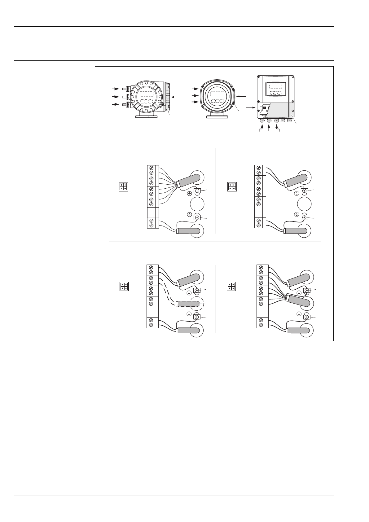
Electrical connection Measuring unit
AB
d
g
b
d
g
b
a
HART*
–27
+26
–25
f f
+24
–23
+22
–21
+20
N (L-) 2
L1 (L+)1
d
e
c
b
a
PA(–)/FF(–)
PA(+)/FF(+)
N (L-)
L1 (L+)
C
d/(g)
b
(d)
PROFIBUS PA*
FOUNDATION Fieldbus*
27
26
–
25
+
24
–
23
+
22
–
21
+
20
2
1
a
d
e
c
b
PROFIBUS DP*
PROFIBUS DP**
MODBUS RS485**
N (L-)
L1 (L+)
27
26
–
25
+
24
–
23
+
22
–
21
+
20
2
1
A (RxD/TxD-N)
B (RxD/TxD-P)
d
e
g
c
–
+
–
+
–
+
N (L-)
L1 (L+)
27
26
25
24
23
22
21
20
2
1
A (RxD/TxD-N)
B (RxD/TxD-P)
f f
b
Connecting the transmitter, cable cross-section: max. 2.5 mm²
A View A (field housing)
B View B (stainless steel field housing)
C View C (wall-mount housing)
*) Fixed communication board
**) Flexible communication board
a Cover of the connection compartment
b Cable for power supply: 85 to 260 V AC, 20 to 55 V AC, 16 to 62 V DC
Terminal No. 1: L1 for AC, L+ for DC
Terminal No. 2: N for AC, L- for DC
c Ground terminal for protective conductor
d Signal cable: see terminal assignment → ä 11
Fieldbus cable:
Terminal No. 26: DP (B) / PA (+) / FF (+) / MODBUS RS485 (B) / (PA, FF: with reverse polarity protection)
Terminal No. 27: DP (A) / PA (-) / FF (-) / MODBUS RS485 (A) / (PA, FF: with reverse polarity protection)
e Earth terminal, signal cable screen / fieldbus cable / RS485 line
f Service connector for connecting service interface FXA 193 (Fieldcheck, FieldCare)
g Signal cable: see terminal assignment → ä 11
Cable for external termination (only for PROFIBUS DP with fixed communication board):
Terminal No. 24: +5 V
Terminal No. 25: DGND
d
e
g
c
b
a0002441
10 Endress+Hauser

Proline Promass 80A, 83A
Electrical connection, terminal assignment
Promass 80
Terminal No. (inputs/outputs)
Order variant 20 (+) / 21 (–) 22 (+) / 23 (–) 24 (+) / 25 (–) 26 (+) / 27 (–)
80***-***********A - - Frequency output Current output, HART
80***-***********D Status input Status output Frequency output Current output, HART
80***-***********H - - - PROFIBUS PA
80***-***********S - -
80***-***********T - -
80***-***********8 Status input Frequency output Current output 2 Current output 1,
Frequency output
Ex i, passive
Frequency output
Ex i, passive
Current output Ex i
Active, HART
Current output Ex i
Passive, HART
HART
Promass 83
The inputs and outputs on the communication board can be either permanently assigned (fixed) or variable
(flexible), depending on the version ordered (see table). Replacements for modules which are defective or
which have to be replaced can be ordered as accessories.
Terminal No. (inputs/outputs)
Order variant 20 (+) / 21 (–) 22 (+) / 23 (–) 24 (+) / 25 (–) 26 (+) / 27 (–)
Fixed communication boards (permanent assignment)
83***-***********A - - Frequency output
83***-***********B Relay output Relay output Frequency output
83***-***********F - - - PROFIBUS PA, Ex i
83***-***********G - - -
83***-***********H - - - PROFIBUS PA
83***-***********J - - +5V (ext. termination) PROFIBUS DP
83***-***********K - -
83***-***********Q - - Status input MODBUS RS485
83***-***********R - - Current output 2
83***-***********S - -
83***-***********T - -
83***-***********U - - Current output 2
Flexible communication boards
83***-***********C Relay output 2 Relay output 1 Frequency output
83***-***********D Status input Relay output Frequency output
83***-***********E Status input Relay output Current output 2
83***-***********L Status input Relay output 2 Relay output 1
- FOUNDATION
Ex i, active
Frequency output
Ex i, passive
Frequency output
Ex i, passive
Ex i, passive
Current output
HART
Current output
HART
FOUNDATION
Fieldbus Ex i
Fieldbus
Current output 1
Ex i active, HART
Current output Ex i
Active, HART
Current output Ex i
Passive, HART
Current output 1
Ex i passive, HART
Current output
HART
Current output
HART
Current output 1
HART
Current output
HART
Endress+Hauser 11
Proline Promass 80A, 83A
Terminal No. (inputs/outputs)
Order variant 20 (+) / 21 (–) 22 (+) / 23 (–) 24 (+) / 25 (–) 26 (+) / 27 (–)
83***-***********M Status input Frequency output 2 Frequency output 1
83***-***********N Current output Frequency output Status input MODBUS RS485
83***-***********P Current output Frequency output Status input PROFIBUS DP
83***-***********V Relay output 2 Relay output 1 Status input PROFIBUS DP
83***-***********W Relay output Current output 3 Current output 2
83***-***********0 Status input Current output 3 Current output 2
83***-***********2 Relay output Current output 2 Frequency output
83***-***********3 Current input Relay output Current output 2 Current output 1
83***-***********4 Current input Relay output Frequency output Current output
83***-***********5 Status input Current input Frequency output Current output
83***-***********6 Status input Current input Current output 2 Current output
83***-***********7 Relay output 2 Relay output 1 Status input MODBUS RS485
Current output
HART
Current output 1
HART
Current output 1
HART
Current output 1
HART
HART
HART
HART
HART
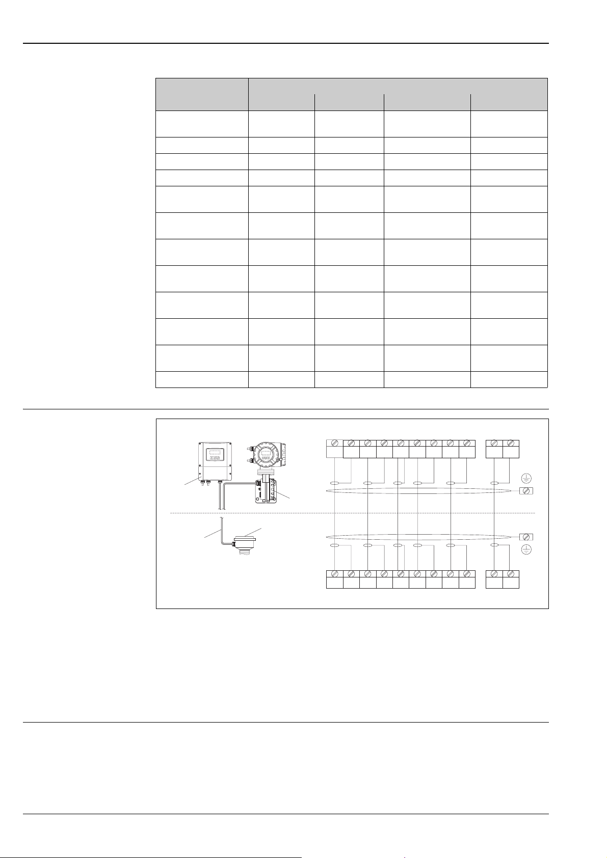
Electrical connection
Remote version
a
b
S1 S1 S2 S2 GND TM TM TT TT
++ ++
4 5 6 7 8 9 10 11 12 41 42
d
d
d
e
c
4 5 6 7 8 9 10 11 12 41 42
++ ++
S1 S1 S2 S2 GND TM TM TT TT
Connection of the remote connection
a Wall-mount housing: non-hazardous area and ATEX II3G / zone 2 → see separate "Ex documentation"
b Wall-mount housing: ATEX II2G / Zone 1 /FM/CSA → see separate "Ex documentation"
c Remote version, flanged version
d Cover for connection compartment or connection housing
e Connecting cable
Terminal No.: 4/5 = grey; 6/7 = green; 8 = yellow; 9/10 = pink; 11/12 = white; 41/42 = brown
a0003681
Supply voltage 85 to 260 V AC, 45 to 65 Hz
20 to 55 V AC, 45 to 65 Hz
16 to 62 V DC
12 Endress+Hauser

Proline Promass 80A, 83A
Cable entries Power-supply and signal cables (inputs/outputs):
• Cable entry M20 × 1.5 (8 to 12 mm)
• Thread for cable entries, 1/2" NPT, G 1/2"
Connecting cable for remote version:
• Cable entry M20 × 1.5 (8 to 12 mm)
• Thread for cable entries, 1/2" NPT, G 1/2"
2
Remote version cable specifications
• 6 × 0.38 mm
• Conductor resistance: ≤50 Ω/km
• Capacitance: core/shield: ≤420 pF/m
• Cable length: max. 20 m (65 ft)
• Operating temperature: max. +105 °C (+221 °F)
Operation in zones of severe electrical interference:
The measuring device complies with the general safety requirements in accordance with EN 61010,
the EMC requirements of IEC/EN 61326, and NAMUR recommendation NE 21/43.
Power consumption AC: <15 VA (including sensor)
DC: <15 W (including sensor)
Switch-on current
• Max. 13.5 A (< 50 ms) at 24 V DC
• Max. 3 A (< 5 ms) at 260 V AC
PVC cable with common shield and individually shielded cores
Power supply failure Promass 80
Lasting min. 1 power cycle
• EEPROM saves measuring system data if the power supply fails
• HistoROM/S-DAT: exchangeable data storage chip with sensor specific data
(nominal diameter, serial number, calibration factor, zero point, etc.)
Promass 83
Lasting min. 1 power cycle:
• EEPROM and T-DAT save measuring system data if the power supply fails
• Histo-ROM/S-DAT: exchangeable data storage chip with sensor specific data
(nominal diameter, serial number, calibration factor, zero point, etc.)
Potential equalisation No special measures for potential equalization are required. For instruments for use in hazardous areas, observe
the corresponding guidelines in the specific Ex documentation.
Endress+Hauser 13
Performance characteristics
Proline Promass 80A, 83A
Reference operating conditions
Maximum measured error The following values refer to the pulse/frequency output. The additional measured error at the current output
• Error limits following ISO/DIS 11631
• Water, typically +20 to +30 °C (+68 to +86 °F); 2 to 4 bar (30 to 60 psi)
• Data according to calibration protocol ±5 °C (±9 °F) and ±2 bar (±30 psi)
• Accuracy based on accredited calibration rigs according to ISO 17025
is typically ±5 μA. Design fundamentals → ä 16.
o.r. = of reading
Mass flow and volume flow (liquid)
• Promass 83A: ±0.10% o.r.
• Promass 80A: ±0.15% o.r.
Mass flow (gas)
Promass 83A, 80A: ±0.50% o.r.
Density (liquid)
• ±0.0005 g/cc (under reference conditions)
• ±0.0005 g/cc (after field density calibration under process conditions)
• ±0.002 g/cc (after special density calibration)
• ±0.02 g/cc (over the entire measuring range of the sensor)
1 g/cc = 1 kg/l
Special density calibration (optional):
• Calibration range: 0.8 to 1.8 g/cc, +5 to +80 °C (+41 to +176 °F)
• Operation range: 0.0 to 5.0 g/cc, –50 to +200 °C (–58 to +392 °F)
Temperature
±0.5 °C ± 0.005 · T °C
(±1 °F ± 0.003 · (T - 32) °F)
T = medium temperature
Zero point stability
DN Max. full scale value Zero point stability
[mm] [inch] [kg/h] or [l/h] [lb/min] [kg/h] or [l/h] [lb/min]
1 1/24" 20 0.73 0.0010 0.000036
2 1/12" 100 3.7 0.0050 0.00018
4 1/8" 450 16.5 0.0225 0.0008
14 Endress+Hauser
 Loading...