

Endress+Hauser Proline Promag W 400, Proline Promag W 400 EtherNet/IP Operating Instructions Manual
BA01214D/06/EN/03.15
71280372
Valid as of version
01.00.zz (Device firmware)
Products Solutions Services
Operating Instructions
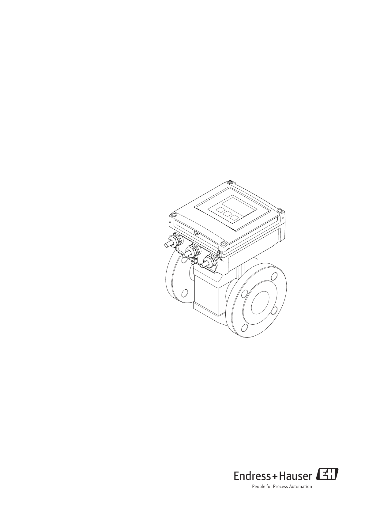
Proline Promag W 400
EtherNet/IP
Electromagnetic flowmeter
AUTHORIZED DISTRIBUTOR:
InstrumentsAndControl.com
Houston, Texas USA
sales@InstrumentsAndControl.com
832-615-3588

Proline Promag W 400 EtherNet/IP
• Make sure the document is stored in a safe place such that it is always available when
working on or with the device.
• To avoid danger to individuals or the facility, read the "Basic safety instructions" section
carefully, as well as all other safety instructions in the document that are specific to
working procedures.
• The manufacturer reserves the right to modify technical data without prior notice. Your
Endress+Hauser Sales Center will supply you with current information and updates to
these Instructions.
2 Endress+Hauser

Proline Promag W 400 EtherNet/IP Table of contents
Table of contents
1 Document information .............. 6
1.1 Document function ..................... 6
1.2 Symbols used .......................... 6
1.2.1 Safety symbols .................. 6
1.2.2 Electrical symbols ................ 6
1.2.3 Tool symbols .................... 6
1.2.4 Symbols for certain types of
information .................... 7
1.2.5 Symbols in graphics ............... 7
1.3 Documentation ........................ 7
1.3.1 Standard documentation ........... 8
1.3.2 Supplementary device-dependent
documentation .................. 8
1.4 Registered trademarks ................... 8
2 Basic safety instructions ............ 9
2.1 Requirements for the personnel ............ 9
2.2 Designated use ........................ 9
2.3 Workplace safety ...................... 10
2.4 Operational safety ..................... 10
2.5 Product safety ........................ 11
2.6 IT security ........................... 11
3 Product description ................ 12
3.1 Product design ........................ 12
4 Incoming acceptance and product
identification ..................... 13
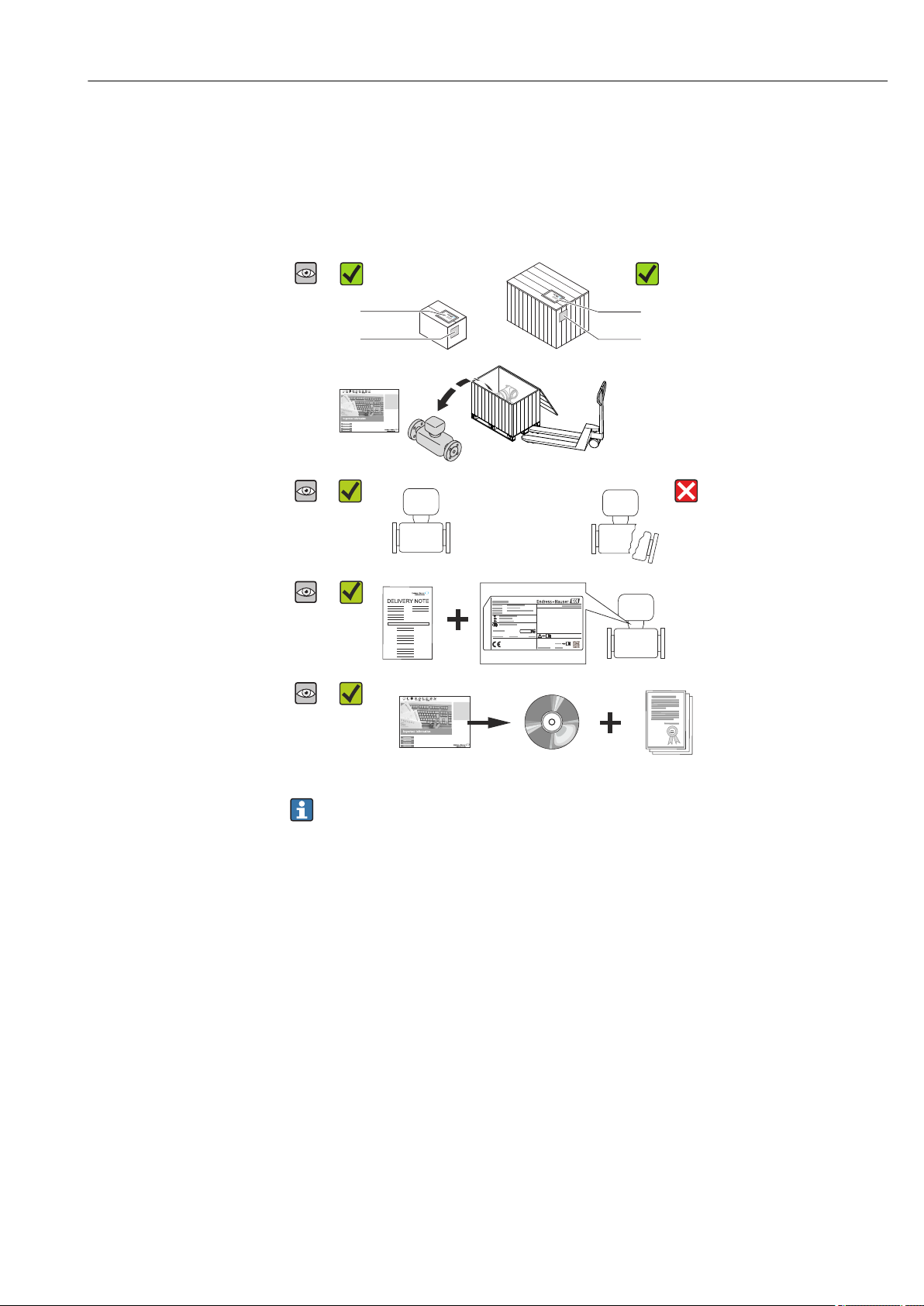
4.1 Incoming acceptance ................... 13
4.2 Product identification ................... 13
4.2.1 Transmitter nameplate ........... 14
4.2.2 Sensor nameplate ............... 15
4.2.3 Symbols on measuring device ...... 16
5 Storage and transport ............. 17
5.1 Storage conditions ..................... 17
5.2 Transporting the product ................ 17
5.2.1 Measuring devices without lifting
lugs ......................... 17
5.2.2 Measuring devices with lifting lugs .. 18
5.2.3 Transporting with a fork lift ........ 18
5.3 Packaging disposal ..................... 18
6 Installation ....................... 19
6.1 Installation conditions .................. 19
6.1.1 Mounting position ............... 19
6.1.2 Requirements from environment and
process ....................... 21
6.1.3 Special mounting instructions ...... 23
6.2 Mounting the measuring device ........... 24
6.2.1 Required tools .................. 24
6.2.2 Preparing the measuring device ..... 24
6.2.3 Mounting the sensor ............. 24
6.2.4 Mounting the transmitter of the
remote version ................. 30
6.2.5 Turning the transmitter housing .... 32
6.2.6 Turning the display module ........ 34
6.3 Post-installation check .................. 35
7 Electrical connection .............. 36
7.1 Connection conditions .................. 36
7.1.1 Required tools .................. 36
7.1.2 Requirements for connecting cable ... 36
7.1.3 Terminal assignment ............. 38
7.1.4 Pin assignment, device plug ........ 39
7.1.5 Shielding and grounding .......... 40
7.1.6 Requirements for the supply unit .... 40
7.1.7 Preparing the measuring device ..... 40
7.1.8 Preparing the connecting cable for
the remote version .............. 40
7.2 Connecting the measuring device .......... 41
7.2.1 Connecting the remote version ..... 41
7.2.2 Connecting the transmitter ........ 43
7.2.3 Ensuring potential equalization ..... 44
7.3 Special connection instructions ............ 46
7.4 Hardware settings ..................... 46
7.4.1 Setting the device address ......... 46
7.5 Ensuring the degree of protection .......... 47
7.5.1 Degree of protection IP66/67, Type
4X enclosure ................... 47
7.5.2 Degree of protection IP68, Type 6P
enclosure, with "Cust-potted" option .. 47
7.6 Post-connection check .................. 47
8 Operation options ................. 49
8.1 Overview of operation options ............ 49
8.2 Structure and function of the operating
menu .............................. 50
8.2.1 Structure of the operating menu .... 50
8.2.2 Operating philosophy ............ 51
8.3 Access to the operating menu via the local
display ............................. 52
8.3.1 Operational display .............. 52
8.3.2 Navigation view ................ 53
8.3.3 Editing view ................... 55
8.3.4 Operating elements .............. 57
8.3.5 Opening the context menu ......... 57
8.3.6 Navigating and selecting from list ... 59
8.3.7 Calling the parameter directly ...... 59
8.3.8 Calling up help text .............. 60
8.3.9 Changing the parameters ......... 61
8.3.10 User roles and related access
authorization .................. 62
8.3.11 Disabling write protection via access
code ......................... 62
Endress+Hauser 3

Table of contents Proline Promag W 400 EtherNet/IP
8.3.12 Enabling and disabling the keypad
lock ......................... 62
8.4 Access to the operating menu via the Web
browser ............................. 63
8.4.1 Function range ................. 63
8.4.2 Prerequisites ................... 63
8.4.3 Establishing a connection ......... 64
8.4.4 Logging on .................... 65
8.4.5 User interface .................. 66
8.4.6 Disabling the Web server .......... 67
8.4.7 Logging out .................... 67
8.5 Access to the operating menu via the
operating tool ........................ 67
8.5.1 Connecting the operating tool ...... 68
8.5.2 FieldCare ..................... 68
9 System integration ................ 70
9.1 Overview of device description files ......... 70
9.1.1 Current version data for the device ... 70
9.1.2 Operating tools ................. 70
9.2 Overview of system files ................. 70
9.3 Integrating the measuring device in the
system ............................. 70
9.4 Cyclic data transmission ................ 71
9.4.1 Block model ................... 71
9.4.2 Input and output groups .......... 71
10 Commissioning .................... 75
10.1 Function check ....................... 75
10.2 Switching on the measuring device ......... 75
10.3 Establishing a connection via FieldCare ...... 75
10.4 Configuring the device address via software .. 75
10.4.1 Ethernet network and Web server ... 75
10.5 Setting the operating language ............ 75
10.6 Configuring the measuring device .......... 76
10.6.1 Defining the tag name ............ 80
10.6.2 Setting the system units .......... 80
10.6.3 Configuring the communication
interface ...................... 82
10.6.4 Configuring the local display ....... 83
10.6.5 Configuring the low flow cut off ..... 84
10.6.6 Configuring empty pipe detection ... 86
10.7 Advanced settings ..................... 87
10.7.1 Carrying out a sensor adjustment .... 89
10.7.2 Configuring the totalizer .......... 89
10.7.3 Carrying out additional display
configurations .................. 91
10.7.4 Performing electrode cleaning ...... 93
10.7.5 Administration configuration ...... 94
10.8 Configuration management .............. 94
10.8.1 Function range of "Configuration
management" parameter .......... 95
10.9 Simulation ........................... 96
10.10 Protecting settings from unauthorized
access .............................. 97
10.10.1 Write protection via access code ..... 97
10.10.2 Write protection via write protection
switch ........................ 98
11 Operation ....................... 100
11.1 Read out and modify current Ethernet
settings ............................ 100
11.2 Reading the device locking status ......... 100
11.3 Adjusting the operating language ......... 101
11.4 Configuring the display ................ 101
11.5 Reading measured values ............... 101
11.5.1 Process variables ............... 101
11.5.2 Totalizer ..................... 102
11.6 Adapting the measuring device to the process
conditions .......................... 102
11.7 Performing a totalizer reset ............. 102
11.8 Showing data logging ................. 103
12 Diagnostics and troubleshooting .. 105
12.1 General troubleshooting ................ 105
12.2 Diagnostic information via light emitting
diodes ............................. 107
12.2.1 Transmitter ................... 107
12.3 Diagnostic information on local display ..... 108
12.3.1 Diagnostic message ............. 108
12.3.2 Calling up remedial measures ..... 110
12.4 Diagnostic information in the Web browser . 111
12.4.1 Diagnostic options .............. 111
12.4.2 Calling up remedy information .... 111
12.5 Diagnostic information in FieldCare ....... 112
12.5.1 Diagnostic options .............. 112
12.5.2 Calling up remedy information .... 113
12.6 Diagnostic information via communication
interface ........................... 113
12.6.1 Reading out diagnostic information 113
12.7 Adapting the diagnostic information ...... 113
12.7.1 Adapting the diagnostic behavior ... 113
12.8 Overview of diagnostic information ....... 114
12.9 Pending diagnostic events .............. 116
12.10 Diagnostic list ....................... 117
12.11 Event logbook ....................... 117
12.11.1 Event history .................. 117
12.11.2 Filtering the event logbook ....... 118
12.11.3 Overview of information events .... 118
12.12 Resetting the measuring device .......... 119
12.12.1 Function scope of "Device reset"
parameter .................... 120
12.13 Device information ................... 120
12.14 Firmware history ..................... 122
13 Maintenance .................... 123
13.1 Maintenance tasks .................... 123
13.1.1 Exterior cleaning ............... 123
13.1.2 Interior cleaning ............... 123
13.1.3 Replacing seals ................ 123
13.2 Measuring and test equipment ........... 123
13.3 Endress+Hauser services ............... 123
14 Repair ........................... 124
14.1 General notes ....................... 124
4 Endress+Hauser

Proline Promag W 400 EtherNet/IP Table of contents
14.2 Spare parts ......................... 124
14.3 Endress+Hauser services ............... 124
14.4 Return ............................. 124
14.5 Disposal ........................... 124
14.5.1 Removing the measuring device .... 124
14.5.2 Disposing of the measuring device .. 125
15 Accessories ...................... 126
15.1 Device-specific accessories .............. 126
15.1.1 For the transmitter ............. 126
15.1.2 For the sensor ................. 126
15.2 Service-specific accessories .............. 126
15.3 System components ................... 127
16 Technical data ................... 128
16.1 Application ......................... 128
16.2 Function and system design ............. 128
16.3 Input .............................. 128
16.4 Output ............................ 131
16.5 Power supply ........................ 134
16.6 Performance characteristics ............. 135
16.7 Installation ......................... 137
16.8 Environment ........................ 137
16.9 Process ............................ 138
16.10 Mechanical construction ............... 139
16.11 Operability ......................... 156
16.12 Certificates and approvals .............. 158
16.13 Application packages .................. 159
16.14 Accessories ......................... 160
16.15 Documentation ...................... 160
17 Appendix ........................ 162
17.1 Overview of the operating menu .......... 162
17.1.1 "Operation" menu ............... 162
17.1.2 "Setup" menu .................. 163
17.1.3 "Diagnostics" menu .............. 166
17.1.4 "Expert" menu ................. 170
Index ................................. 181
Endress+Hauser 5
Document information Proline Promag W 400 EtherNet/IP
DANGER
WARNING
CAUTION
NOTICE
1 Document information
1.1 Document function
These Operating Instructions contain all the information that is required in various phases
of the life cycle of the device: from product identification, incoming acceptance and
storage, to mounting, connection, operation and commissioning through to
troubleshooting, maintenance and disposal.
1.2 Symbols used
1.2.1 Safety symbols
Symbol Meaning
DANGER!
This symbol alerts you to a dangerous situation. Failure to avoid this situation will result in
serious or fatal injury.
WARNING!
This symbol alerts you to a dangerous situation. Failure to avoid this situation can result in
serious or fatal injury.
CAUTION!
This symbol alerts you to a dangerous situation. Failure to avoid this situation can result in
minor or medium injury.
NOTE!
This symbol contains information on procedures and other facts which do not result in
personal injury.
1.2.2 Electrical symbols
Symbol Meaning Symbol Meaning
Direct current Alternating current
Direct current and alternating current Ground connection
Protective ground connection
A terminal which must be connected
to ground prior to establishing any
other connections.
1.2.3 Tool symbols
Symbol Meaning
Torx screwdriver
Phillips head screwdriver
A grounded terminal which, as far as
the operator is concerned, is
grounded via a grounding system.
Equipotential connection
A connection that has to be connected
to the plant grounding system: This
may be a potential equalization line
or a star grounding system depending
on national or company codes of
practice.
Open-ended wrench
6 Endress+Hauser
Proline Promag W 400 EtherNet/IP Document information
,…,
,…,
-
.
1.2.4 Symbols for certain types of information
Symbol Meaning
Permitted
Procedures, processes or actions that are permitted.
Preferred
Procedures, processes or actions that are preferred.
Forbidden
Procedures, processes or actions that are forbidden.
Tip
Indicates additional information.
Reference to documentation
Reference to page
Reference to graphic
Series of steps
Result of a sequence of actions
Help in the event of a problem
Visual inspection
1.2.5 Symbols in graphics
Symbol Meaning Symbol Meaning
1, 2, 3,... Item numbers
A, B, C, ... Views A-A, B-B, C-C, ... Sections
Hazardous area
Flow direction
Series of steps
Safe area (non-hazardous area)
1.3 Documentation
For an overview of the scope of the associated Technical Documentation, refer to the
following:
• The CD-ROM provided for the device (depending on the device version, the CD-ROM
might not be part of the delivery!)
• The W@M Device Viewer : Enter the serial number from the nameplate
(www.endress.com/deviceviewer)
• The Endress+Hauser Operations App: Enter the serial number from the nameplate
or scan the 2-D matrix code (QR code) on the nameplate.
For a detailed list of the individual documents along with the documentation code
Endress+Hauser 7

Document information Proline Promag W 400 EtherNet/IP
1.3.1 Standard documentation
Document type Purpose and content of the document
Technical Information Planning aid for your device
The document contains all the technical data on the device and provides
an overview of the accessories and other products that can be ordered for
the device.
Brief Operating Instructions Guide that takes you quickly to the 1st measured value
The Brief Operating Instructions contain all the essential information
from incoming acceptance to initial commissioning.
1.3.2 Supplementary device-dependent documentation
Additional documents are supplied depending on the device version ordered: Always
comply strictly with the instructions in the supplementary documentation. The
supplementary documentation is an integral part of the device documentation.
1.4 Registered trademarks
EtherNet/IP
Trademark of ODVA, Inc.
Microsoft
Registered trademark of the Microsoft Corporation, Redmond, Washington, USA
Applicator®, FieldCare®, Field XpertTM, HistoROM®, Heartbeat Technology
Registered or registration-pending trademarks of the Endress+Hauser Group
TM
®
TM
8 Endress+Hauser

Proline Promag W 400 EtherNet/IP Basic safety instructions
2 Basic safety instructions
2.1 Requirements for the personnel
The personnel for installation, commissioning, diagnostics and maintenance must fulfill
the following requirements:
Trained, qualified specialists must have a relevant qualification for this specific function
‣
and task
Are authorized by the plant owner/operator
‣
Are familiar with federal/national regulations
‣
Before beginning work, the specialist staff must have read and understood the
‣
instructions in the Operating Instructions and supplementary documentation as well as
in the certificates (depending on the application)
Following instructions and basic conditions
‣
The operating personnel must fulfill the following requirements:
Being instructed and authorized according to the requirements of the task by the
‣
facility's owner-operator
Following the instructions in these Operating Instructions
‣
2.2 Designated use
Application and media
The measuring device described in these Instructions is intended only for flow
measurement of liquids with a minimum conductivity of 5 μS/cm.
Depending on the version ordered, the measuring device can also measure potentially
explosive, flammable, poisonous and oxidizing media.
Measuring devices for use in hazardous areas, in hygienic applications or in applications
where there is an increased risk due to process pressure, are labeled accordingly on the
nameplate.
To ensure that the measuring device remains in proper condition for the operation time:
Only use the measuring device in full compliance with the data on the nameplate and
‣
the general conditions listed in the Operating Instructions and supplementary
documentation.
Based on the nameplate, check whether the ordered device is permitted for the
‣
intended use in the hazardous area (e.g. explosion protection, pressure vessel safety).
Use the measuring device only for media against which the process-wetted materials
‣
are adequately resistant.
If the measuring device is not operated at atmospheric temperature, compliance with
‣
the relevant basic conditions specified in the associated device documentation is
absolutely essential: "Documentation" section → 7.
This measuring device is optionally tested in accordance with OIML R49 and has an
EC type-examination certificate according to Measuring Instruments Directive
2004/22/EC (MID) for service subject to legal metrological control ("custody transfer")
for cold water (Annex MI‐001).
The permitted fluid temperature in these applications is 0 to 50 °C.
Incorrect use
Non-designated use can compromise safety. The manufacturer is not liable for damage
caused by improper or non-designated use.
Endress+Hauser 9

Basic safety instructions Proline Promag W 400 EtherNet/IP
WARNING
L
Danger of breakage of the sensor due to corrosive or abrasive fluids!
Verify the compatibility of the process fluid with the sensor material.
‣
Ensure the resistance of all fluid-wetted materials in the process.
‣
Observe the specified pressure and temperature range.
‣
Verification for borderline cases:
For special fluids and fluids for cleaning, Endress+Hauser is glad to provide assistance
‣
in verifying the corrosion resistance of fluid-wetted materials, but does not accept any
warranty or liability as minute changes in the temperature, concentration or level of
contamination in the process can alter the corrosion resistance properties.
Residual risks
The external surface temperature of the housing can increase by max. 10 K due to the
power consumption of the electronic components. Hot process fluids passing through the
measuring device will further increase the surface temperature of the housing. The surface
of the sensor, in particular, can reach temperatures which are close to the fluid
temperature.
Possible burn hazard due to fluid temperatures!
For elevated fluid temperature, ensure protection against contact to prevent burns.
‣
2.3 Workplace safety
For work on and with the device:
Wear the required personal protective equipment according to federal/national
‣
regulations.
For welding work on the piping:
Do not ground the welding unit via the measuring device.
‣
If working on and with the device with wet hands:
It is recommended to wear gloves on account of the higher risk of electric shock.
‣
2.4 Operational safety
Risk of injury.
Operate the device in proper technical condition and fail-safe condition only.
‣
The operator is responsible for interference-free operation of the device.
‣
Conversions to the device
Unauthorized modifications to the device are not permitted and can lead to unforeseeable
dangers.
If, despite this, modifications are required, consult with Endress+Hauser.
‣
Repair
To ensure continued operational safety and reliability,
Carry out repairs on the device only if they are expressly permitted.
‣
Observe federal/national regulations pertaining to repair of an electrical device.
‣
Use original spare parts and accessories from Endress+Hauser only.
‣
Environmental requirements
If a plastic transmitter housing is permanently exposed to certain steam and air mixtures,
this can damage the housing.
If you are unsure, please contact your Endress+Hauser Sales Center for clarification.
‣
If used in an approval-related area, observe the information on the nameplate.
‣
10 Endress+Hauser

Proline Promag W 400 EtherNet/IP Basic safety instructions
2.5 Product safety
This measuring device is designed in accordance with good engineering practice to meet
state-of-the-art safety requirements, has been tested, and left the factory in a condition in
which it is safe to operate.
It meets general safety standards and legal requirements. It also complies with the EC
directives listed in the device-specific EC Declaration of Conformity. Endress+Hauser
confirms this by affixing the CE mark to the device.
2.6 IT security
We only provide a warranty if the device is installed and used as described in the
Operating Instructions. The device is equipped with security mechanisms to protect it
against any inadvertent changes to the device settings.
IT security measures in line with operators' security standards and designed to provide
additional protection for the device and device data transfer must be implemented by the
operators themselves.
Endress+Hauser 11
Product description Proline Promag W 400 EtherNet/IP
1
2
3
5
6
8
7
4
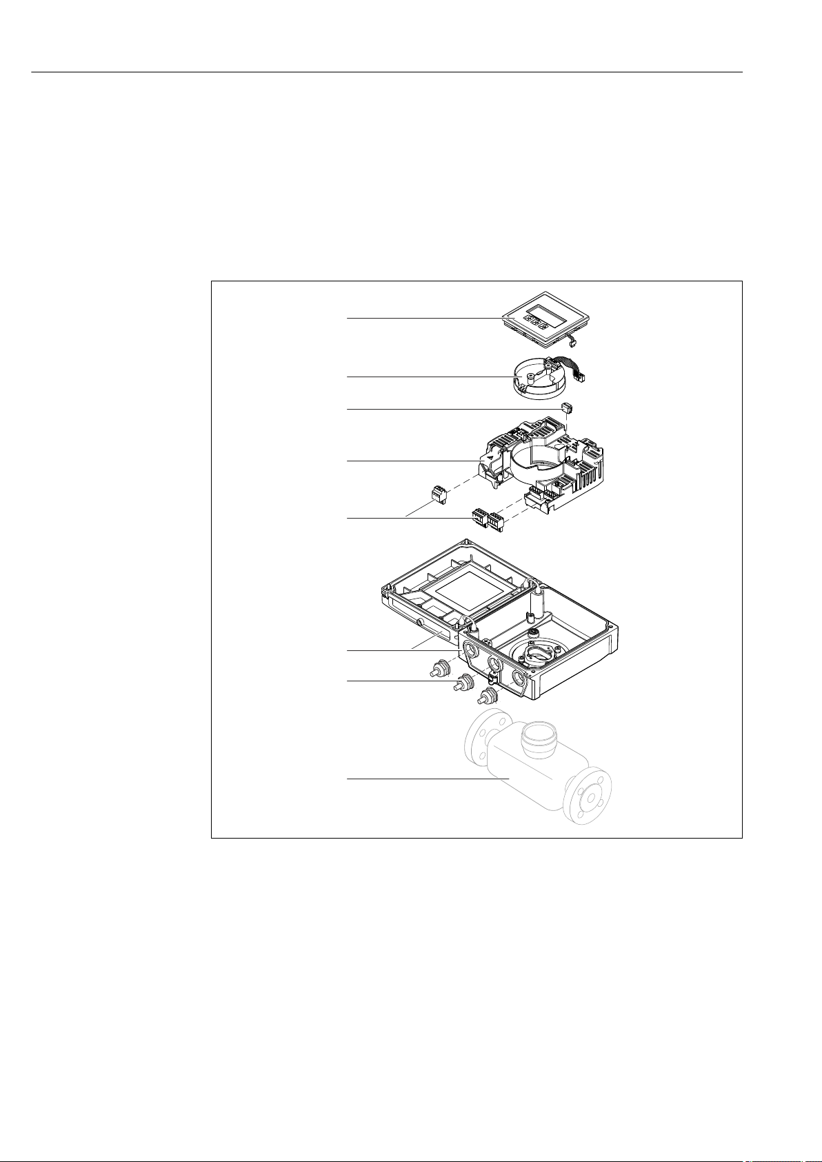
3 Product description
The device consists of a transmitter and a sensor.
Two device versions are available:
• Compact version - transmitter and sensor form a mechanical unit.
• Remote version - transmitter and sensor are mounted in separate locations.
3.1 Product design
1 Important components of the compact version
1 Display module
2 Smart sensor electronics module
3 HistoROM DAT (plug-in memory)
4 Main electronics module
5 Terminals (screw terminals, some available as plug-in terminals) or fieldbus connectors
6 Transmitter housing, compact version
7 Cable glands
8 Sensor, compact version
A0017218
12 Endress+Hauser
Proline Promag W 400 EtherNet/IP Incoming acceptance and product identification
1
+
2
1
+
2
4 Incoming acceptance and product
identification
4.1 Incoming acceptance
Are the order codes on the
delivery note (1) and the
product sticker (2)
identical?
Are the goods undamaged?
Do the nameplate data
match the ordering
information on the delivery
note?
Is the CD-ROM with the
Technical Documentation
(depends on device
version) and documents
present?
• If one of the conditions is not satisfied, contact your Endress+Hauser Sales Center.
• Depending on the device version, the CD-ROM might not be part of the delivery!
The Technical Documentation is available via the Internet or via the Endress+Hauser
Operations App, see the "Product identification" section → 14.
4.2 Product identification
The following options are available for identification of the measuring device:
• Nameplate specifications
• Order code with breakdown of the device features on the delivery note
• Enter serial numbers from nameplates in W@M Device Viewer
(www.endress.com/deviceviewer): All information about the measuring device is
displayed.
• Enter the serial number from the nameplates into the Endress+Hauser Operations App
or scan the 2-D matrix code (QR code) on the nameplate with the Endress+Hauser
Operations App: all the information for the measuring device is displayed.
Endress+Hauser 13
Incoming acceptance and product identification Proline Promag W 400 EtherNet/IP
Order code:
i
Ext. ord. cd.:
Ser. no.:
Patents
i
Date:
1
2
3 4 5 6 7
8
9
10
111213
For an overview of the scope of the associated Technical Documentation, refer to the
following:
• The chapters "Additional standard documentation on the device" → 8 and
"Supplementary device-dependent documentation" → 8
• The W@M Device Viewer: Enter the serial number from the nameplate
(www.endress.com/deviceviewer)
• The Endress+Hauser Operations App: Enter the serial number from the nameplate or
scan the 2-D matrix code (QR code) on the nameplate.
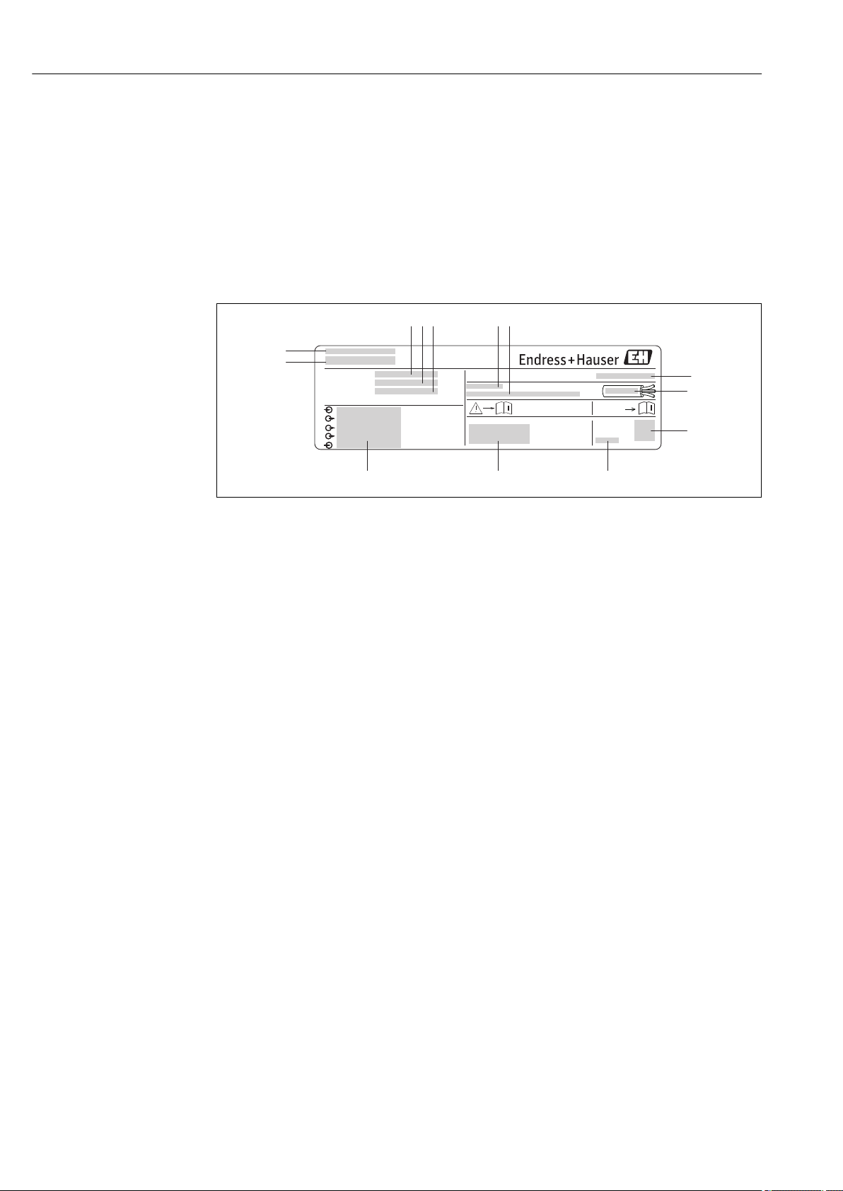
4.2.1 Transmitter nameplate
2 Example of a transmitter nameplate
1 Manufacturing location
2 Name of the transmitter
3 Order code
4 Serial number (Ser. no.)
5 Extended order code (Ext. ord. cd.)
6 Permitted ambient temperature (Ta)
7 Firmware version (FW) and device revision (Dev.Rev.) from the factory
8 Degree of protection
9 Permitted temperature range for cable
10 2-D matrix code
11 Manufacturing date: year-month
12 CE mark, C-Tick
13 Electrical connection data, e.g. available inputs and outputs, supply voltage
A0017346
14 Endress+Hauser
Proline Promag W 400 EtherNet/IP Incoming acceptance and product identification
i
Patents
i
Material:
Tm:
Ext. ord. cd.:
Order Code:
Ser.No.:
Date:
21
3
4
5
6 7
8
9
10
11
13
12
14
15
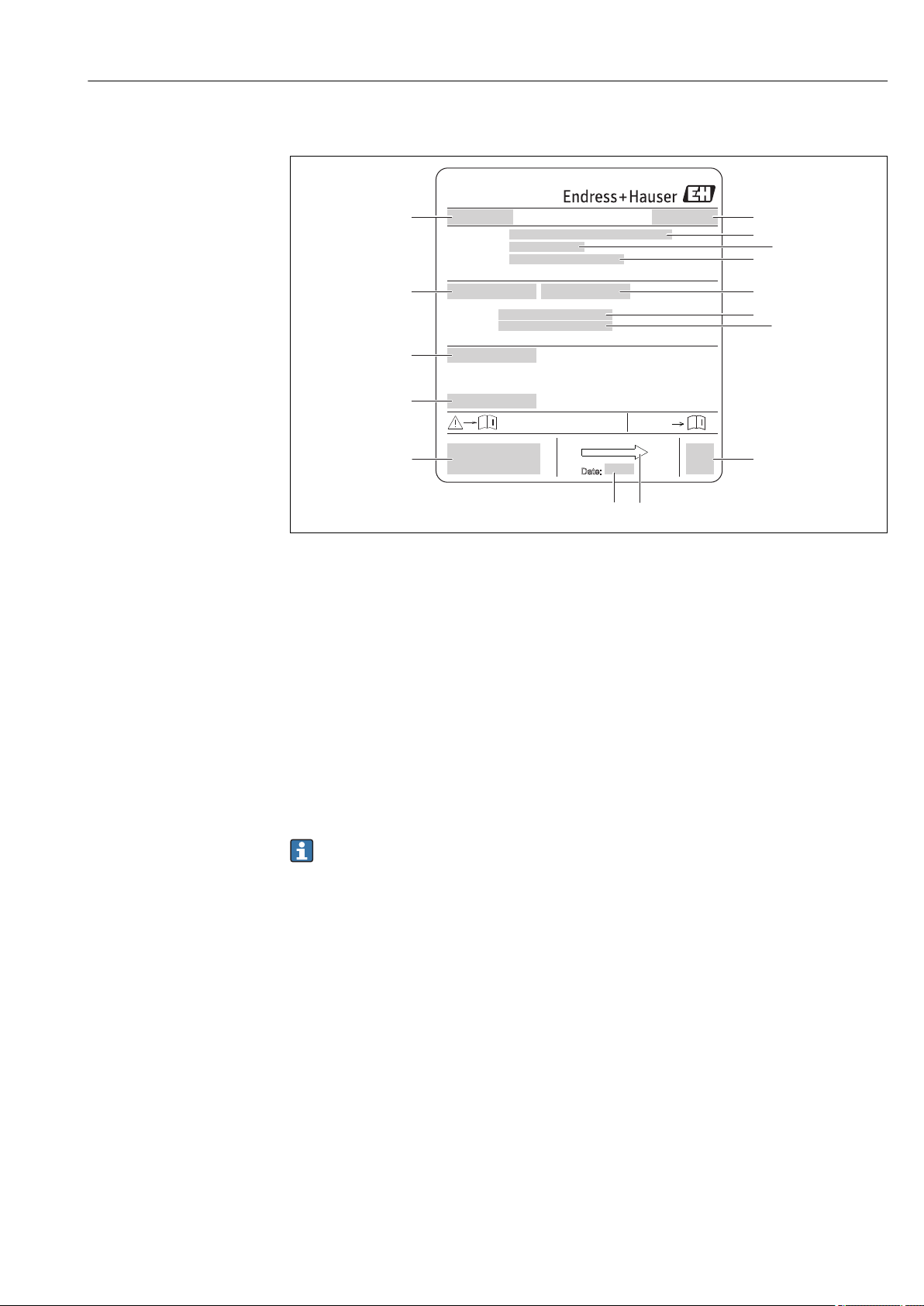
4.2.2 Sensor nameplate
3 Example of sensor nameplate
1 Name of the sensor
2 Manufacturing location
3 Order code
4 Serial number (ser. no.)
5 Extended order code (ext. ord. cd.)
6 Nominal diameter of sensor
7 Test pressure of the sensor
8 Fluid temperature range
9 Material of lining and electrodes
10 Degree of protection: e.g. IP, NEMA
11 Permitted ambient temperature (Ta)
12 2-D matrix code
13 CE mark, C-Tick
14 Flow direction
15 Manufacturing date: year-month
Order code
The measuring device is reordered using the order code.
Extended order code
• The device type (product root) and basic specifications (mandatory features) are
always listed.
• Of the optional specifications (optional features), only the safety and approvalrelated specifications are listed (e.g. LA). If other optional specifications are also
ordered, these are indicated collectively using the # placeholder symbol (e.g. #LA#).
• If the ordered optional specifications do not include any safety and approval-related
specifications, they are indicated by the + placeholder symbol (e.g. XXXXXX-ABCDE
+).
A0017186
Endress+Hauser 15

Incoming acceptance and product identification Proline Promag W 400 EtherNet/IP
4.2.3 Symbols on measuring device
Symbol Meaning
WARNING!
This symbol alerts you to a dangerous situation. Failure to avoid this situation can result in serious
or fatal injury.
Reference to documentation
Refers to the corresponding device documentation.
Protective ground connection
A terminal which must be connected to ground prior to establishing any other connections.
16 Endress+Hauser
Proline Promag W 400 EtherNet/IP Storage and transport
5 Storage and transport
5.1 Storage conditions
Observe the following notes for storage:
• Store in the original packaging to ensure protection from shock.
• Do not remove protective covers or protective caps installed on process connections.
They prevent mechanical damage to the sealing surfaces and contamination in the
measuring tube.
• Protect from direct sunlight to avoid unacceptably high surface temperatures.
• Select a storage location where moisture cannot collect in the measuring device as
fungus and bacteria infestation can damage the lining.
• Store in a dry and dust-free place.
• Do not store outdoors.
• Storage temperature→ 137
5.2 Transporting the product
Transport the measuring device to the measuring point in the original packaging.
A0015604
Do not remove protective covers or caps installed on process connections. They
prevent mechanical damage to the sealing surfaces and contamination in the
measuring tube.
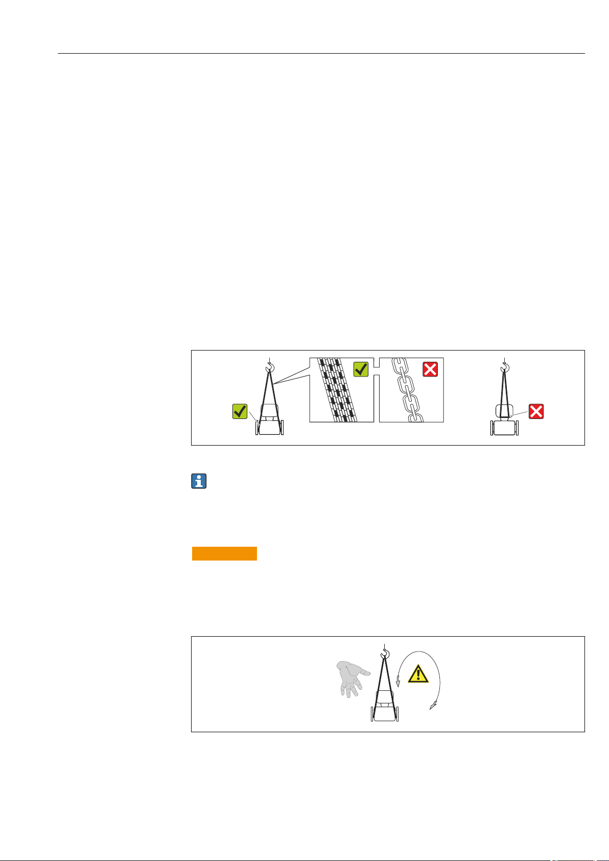
5.2.1 Measuring devices without lifting lugs
WARNING
L
Center of gravity of the measuring device is higher than the suspension points of the
webbing slings.
Risk of injury if the measuring device slips.
Secure the measuring device against slipping or turning.
‣
Observe the weight specified on the packaging (stick-on label).
‣
A0015606
Endress+Hauser 17
Storage and transport Proline Promag W 400 EtherNet/IP
5.2.2 Measuring devices with lifting lugs
CAUTION
L
Special transportation instructions for devices with lifting lugs
Only use the lifting lugs fitted on the device or flanges to transport the device.
‣
The device must always be secured at two lifting lugs at least.
‣
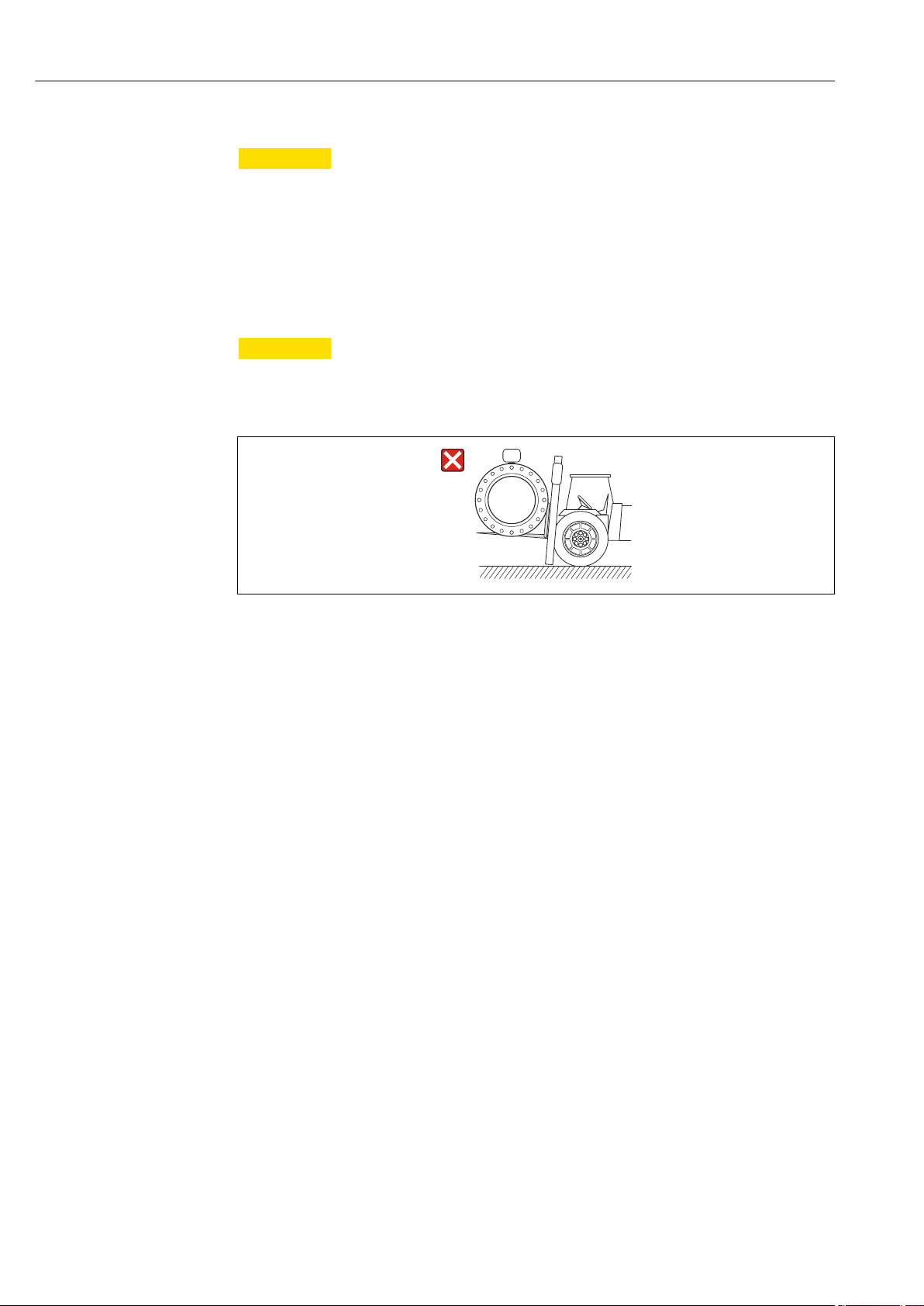
5.2.3 Transporting with a fork lift
If transporting in wood crates, the floor structure enables the crates to be lifted lengthwise
or at both sides using a forklift.
CAUTION
L
Risk of damaging the magnetic coil
If transporting by forklift, do not lift the sensor by the metal casing.
‣
This would buckle the casing and damage the internal magnetic coils.
‣
5.3 Packaging disposal
All packaging materials are environmentally friendly and 100% recyclable:
• Measuring device secondary packaging: polymer stretch film that conforms to EC
Directive 2002/95/EC (RoHS).
• Packaging:
– Wood crate, treated in accordance with ISPM 15 standard, which is confirmed by the
affixed IPPC logo.
or
– Carton in accordance with European Packaging Directive 94/62EC; recyclability is
confirmed by the affixed RESY symbol.
• Seaworthy packaging (optional): Wood crate, treated in accordance with ISPM 15
standard, which is confirmed by the affixed IPPC logo.
• Carrying and mounting hardware:
– Disposable plastic pallet
– Plastic straps
– Plastic adhesive strips
• Dunnage: Paper cushion
A0023726
18 Endress+Hauser
Proline Promag W 400 EtherNet/IP Installation
h
h
2
1
6 Installation
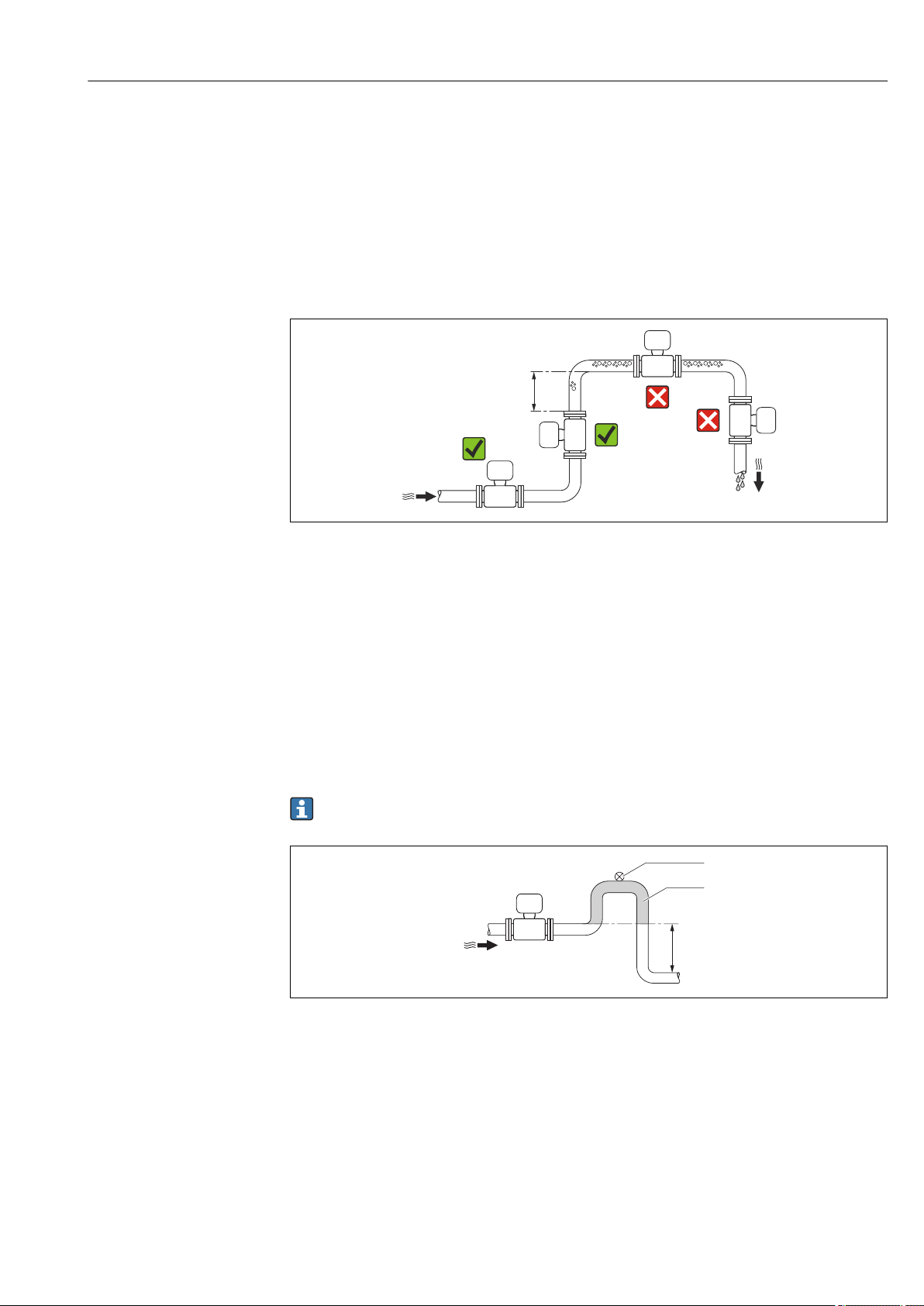
6.1 Installation conditions
6.1.1 Mounting position
Mounting location
A0023343
Preferably install the sensor in an ascending pipe, and ensure a sufficient distance to the
next pipe elbow: h ≥ 2 × DN
To prevent measuring errors arising from accumulation of gas bubbles in the measuring
tube, avoid the following mounting locations in the pipe:
• Highest point of a pipeline.
• Directly upstream of a free pipe outlet in a down pipe.
Installation in down pipes
Install a siphon with a vent valve downstream of the sensor in down pipes whose length h
≥ 5 m (16.4 ft). This precaution is to avoid low pressure and the consequent risk of
damage to the measuring tube. This measure also prevents the system losing prime.
For information on the liner's resistance to partial vacuum
A0017064
4 Installation in a down pipe
1 Vent valve
2 Pipe siphon
h Length of down pipe
Installation in partially filled pipes
A partially filled pipe with a gradient necessitates a drain-type configuration.
Endress+Hauser 19
Installation Proline Promag W 400 EtherNet/IP
³ 5 × DN
³ 2 × DN
1
2
3
2
A0017063
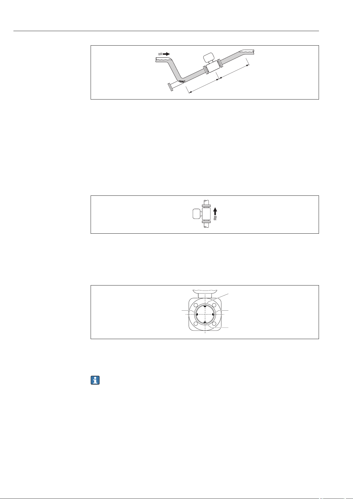
Orientation
The direction of the arrow on the sensor nameplate helps you to install the sensor
according to the flow direction (direction of medium flow through the piping).
An optimum orientation position helps avoid gas and air accumulations and deposits in
the measuring tube.
The measuring device also offers the empty pipe detection function to detect partially filled
measuring pipes in the event of outgassing fluids or variable process pressures.
Vertical
Optimum for self-emptying pipe systems and for use in conjunction with empty pipe
detection.
Horizontal
1 EPD electrode for empty pipe detection
2 Measuring electrodes for signal detection
3 Reference electrode for potential equalization
• The measuring electrode plane must be horizontal. This prevents brief insulation of
the two measuring electrodes by entrained air bubbles.
• Empty pipe detection only works if the transmitter housing is pointing upwards as
otherwise there is no guarantee that the empty pipe detection function will actually
respond to a partially filled or empty measuring tube.
A0015591
A0016260
Inlet and outlet runs
If possible, install the sensor upstream from fittings such as valves, T-pieces or elbows.
Observe the following inlet and outlet runs to comply with accuracy specifications:
20 Endress+Hauser
Proline Promag W 400 EtherNet/IP Installation
5 × DN≥
2 × DN≥
A0016275
To keep within the in-service maximum permissible errors for custody transfer no
additional requirements apply with regard to the graphic illustrated above.
Installation dimensions
For the dimensions and installation lengths of the device, see the "Technical
Information" document, "Mechanical construction" section
6.1.2 Requirements from environment and process
Ambient temperature range
Transmitter –40 to +60 °C (–40 to +140 °F)
Local display –20 to +60 °C (–4 to +140 °F), the readability of the display may be
impaired at temperatures outside the temperature range.
Sensor
Liner Do not exceed or fall below the permitted temperature range of the liner .
If operating outdoors:
• Install the measuring device in a shady location.
• Avoid direct sunlight, particularly in warm climatic regions.
• Avoid direct exposure to weather conditions.
Temperature tables
Observe the interdependencies between the permitted ambient and fluid
temperatures when operating the device in hazardous areas.
For detailed information on the temperature tables, see the separate document
entitled "Safety Instructions" (XA) for the device.
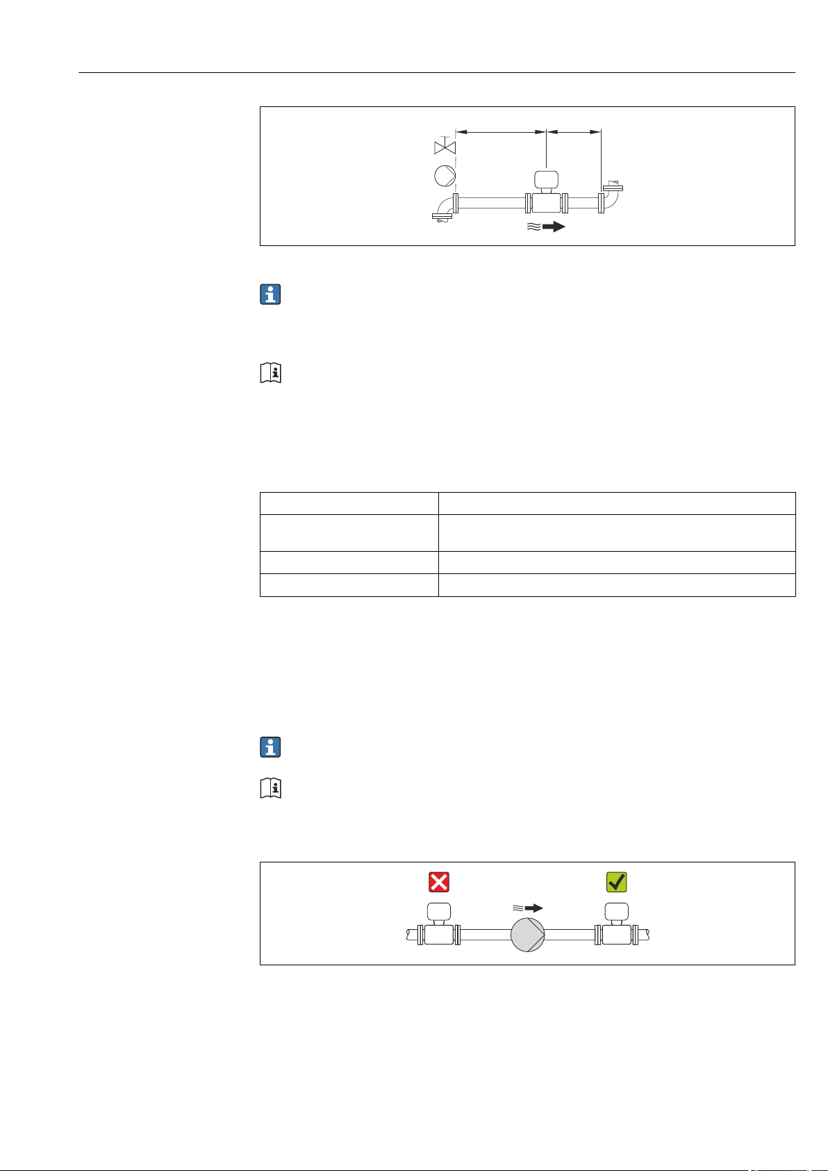
System pressure
Endress+Hauser 21
A0015594
Installation Proline Promag W 400 EtherNet/IP
L
Never install the sensor on the pump suction side in order to avoid the risk of low pressure,
and thus damage to the liner.
Furthermore, install pulse dampers if reciprocating, diaphragm or peristaltic pumps
are used.
• For information on the liner's resistance to partial vacuum → 139
• For information on the shock resistance of the measuring system → 138
• For information on the vibration resistance of the measuring system → 138
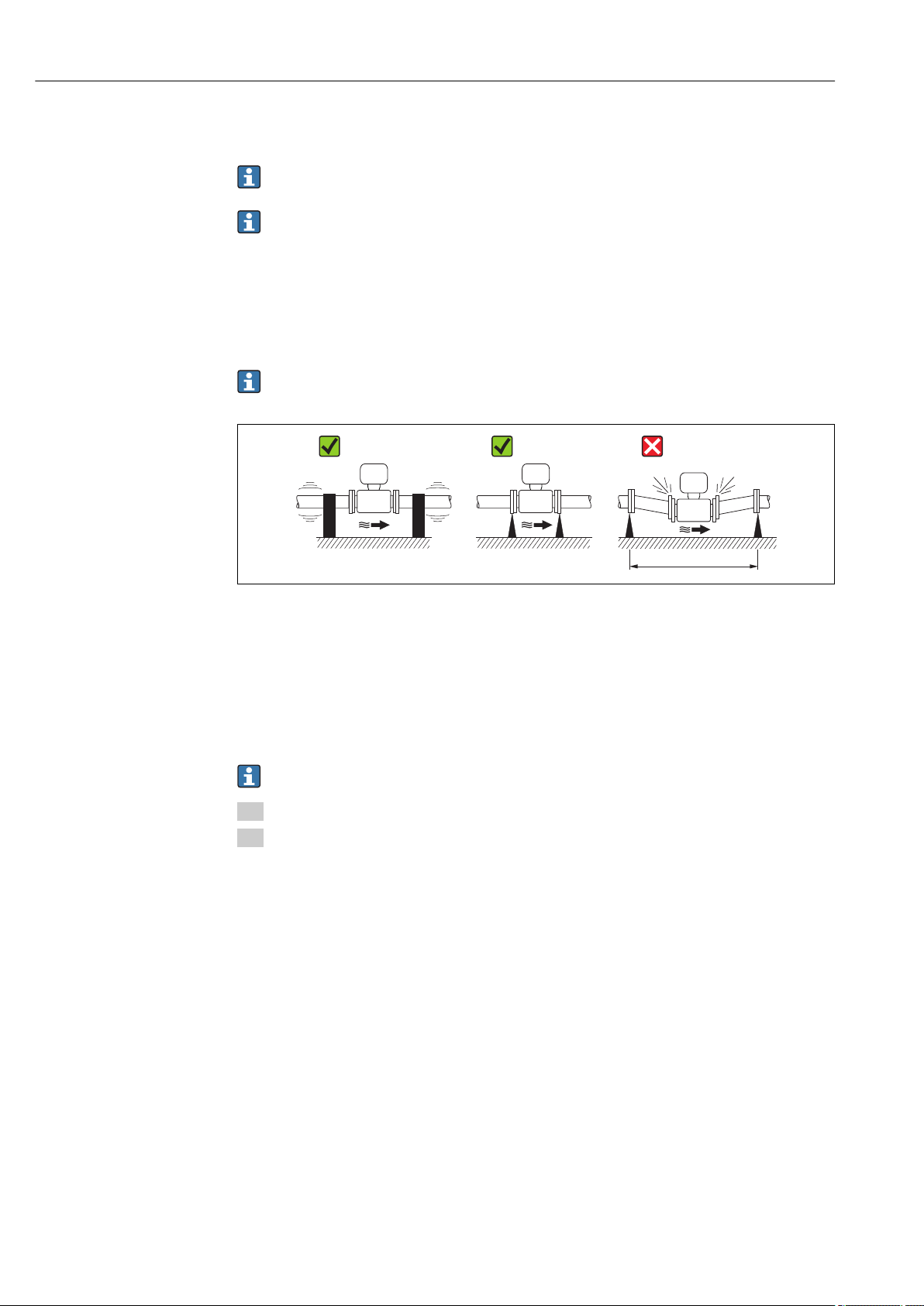
Vibrations
In the event of very strong vibrations, the pipe and sensor must be supported and fixed.
It is also advisable to mount the sensor and transmitter separately.
• For information on the shock resistance of the measuring system → 138
• For information on the vibration resistance of the measuring system → 138
A0016266
5 Measures to avoid device vibrations (L > 10 m (33 ft))
Adapters
Suitable adapters to DIN EN 545 (double-flange reducers) can be used to install the sensor
in larger-diameter pipes. The resultant increase in the rate of flow improves measuring
accuracy with very slow-moving fluids. The nomogram shown here can be used to
calculate the pressure loss caused by reducers and expanders.
The nomogram only applies to liquids with a viscosity similar to that of water.
1. Calculate the ratio of the diameters d/D.
2. From the nomogram read off the pressure loss as a function of flow velocity
(downstream from the reduction) and the d/D ratio.
22 Endress+Hauser
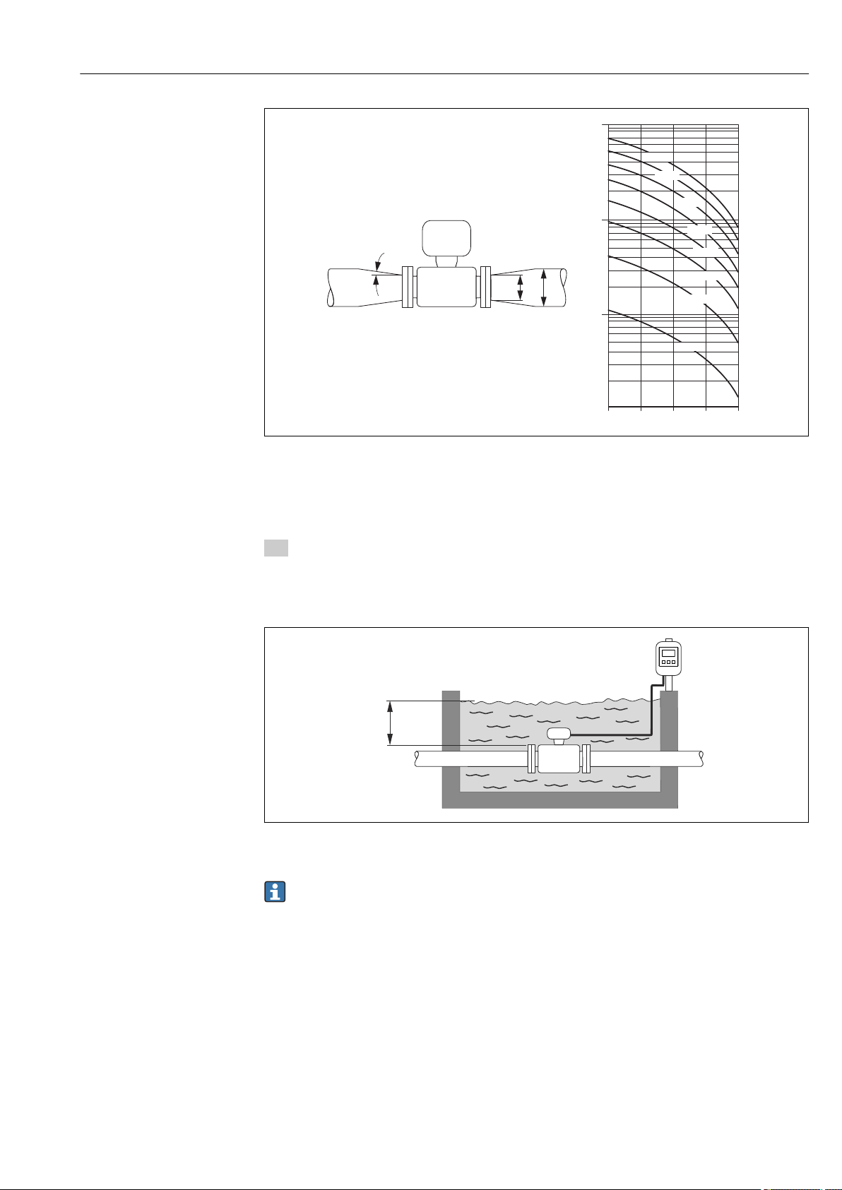
Proline Promag W 400 EtherNet/IP Installation
100
10
0.5
d / D
[mbar]
0.6 0.7 0.8 0.9
1 m/s
2 m/s
3 m/s
4 m/s
5 m/s
6 m/s
7 m/s
8 m/s
1
D
d
max. 8°
≤ ≤3 ( 10)
A0016359
6.1.3 Special mounting instructions
Display protection
To ensure that the optional display protection can be easily opened, maintain the
‣
following minimum head clearance: 350 mm (13.8 in)
Permanent immersion in water
6 Engineering unit in m(ft)
Replacement of cable gland on connection housing → 135
A0017296
Endress+Hauser 23

Installation Proline Promag W 400 EtherNet/IP
Buried applications
A0017298
6.2 Mounting the measuring device
6.2.1 Required tools
For transmitter
• Torque wrench
• For wall mounting:
Open-ended wrench for hexagonal screw max. M5
• For pipe mounting:
– Open-ended wrench AF 8
– Phillips head screwdriver PH 2
• For turning the transmitter housing (compact version):
– Phillips head screwdriver PH 2
– Torx screwdriver TX 20
– Open-ended wrench AF 7
For sensor
For flanges and other process connections:
• Screws, nuts, seals etc. are not included in the scope of supply and must be provided by
the customer.
• Appropriate mounting tools
6.2.2 Preparing the measuring device
1. Remove all remaining transport packaging.
2. Remove any protective covers or protective caps present from the sensor.
3. Remove stick-on label on the electronics compartment cover.
6.2.3 Mounting the sensor
WARNING
L
Danger due to improper process sealing!
Ensure that the inside diameters of the gaskets are greater than or equal to that of the
‣
process connections and piping.
Ensure that the gaskets are clean and undamaged.
‣
Install the gaskets correctly.
‣
1. Ensure that the direction of the arrow on the sensor matches the flow direction of
the medium.
24 Endress+Hauser
Proline Promag W 400 EtherNet/IP Installation
2. To ensure compliance with device specifications, install the measuring device
between the pipe flanges in a way that it is centered in the measurement section.
3. If using ground disks, comply with the Installation Instructions provided.
4. Observe required screw tightening torques → 25.
5. Install the measuring device or turn the transmitter housing so that the cable entries
do not point upwards.
A0013964
Mounting the seals
CAUTION
L
An electrically conductive layer could form on the inside of the measuring tube!
Risk of measuring signal short circuit.
Do not use electrically conductive sealing compounds such as graphite.
‣
Comply with the following instructions when installing seals:
• Make sure that the seals do not protrude into the piping cross-section.
• For DIN flanges: only use seals according to DIN EN 1514-1.
• For "hard rubber" lining: additional seals are always required.
• For "polyurethane" lining: generally additional seals are not required.
Mounting the ground cable/ground disks
Comply with the information on potential equalization and detailed mounting instructions
for the use of ground cables/ground disks → 44.
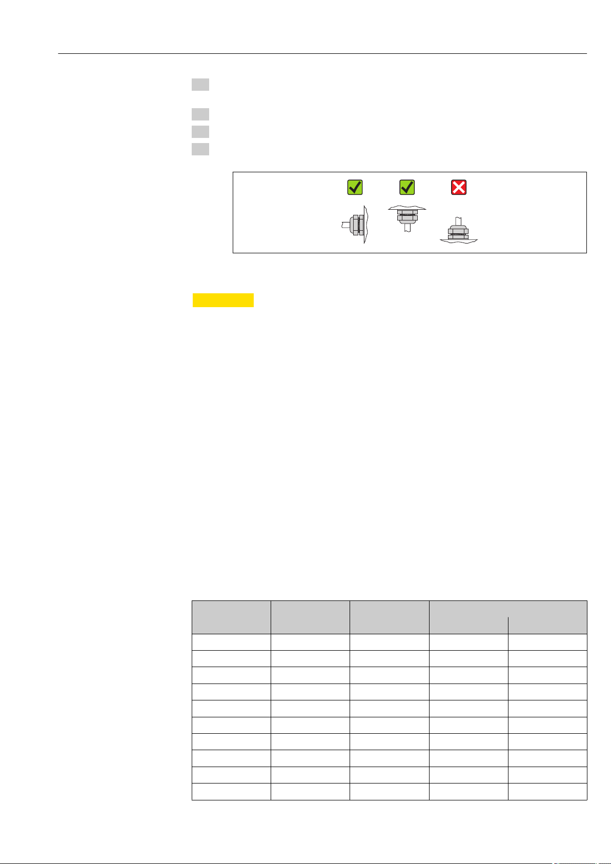
Screw tightening torques
Please note the following:
• The screw tightening torques listed below apply only to lubricated threads and to pipes
not subjected to tensile stress.
• Tighten the screws uniformly and in diagonally opposite sequence.
• Overtightening the screws will deform the sealing faces or damage the seals.
Screw tightening torques for EN 1092-1 (DIN 2501), PN 6/10/16/25/40
Nominal diameter Pressure rating Threaded fasteners Max. screw tightening torque [Nm]
[mm] [bar] [mm] Hard rubber Polyurethane
25 PN 40 4 × M12 – 15
32 PN 40 4 × M16 – 24
40 PN 40 4 × M16 – 31
50 PN 40 4 × M16 48 40
1)
65
65 PN 40 8 × M16 32 27
80 PN 16 8 × M16 40 34
80 PN 40 8 × M16 40 34
100 PN 16 8 × M16 43 36
100 PN 40 8 × M20 59 50
PN 16 8 × M16 32 27
Endress+Hauser 25

Installation Proline Promag W 400 EtherNet/IP
Nominal diameter Pressure rating Threaded fasteners Max. screw tightening torque [Nm]
[mm] [bar] [mm] Hard rubber Polyurethane
125 PN 16 8 × M16 56 48
125 PN 40 8 × M24 83 71
150 PN 16 8 × M20 74 63
150 PN 40 8 × M24 104 88
200 PN 10 8 × M20 106 91
200 PN 16 12 × M20 70 61
200 PN 25 12 × M24 104 92
250 PN 10 12 × M20 82 71
250 PN 16 12 × M24 98 85
250 PN 25 12 × M27 150 134
300 PN 10 12 × M20 94 81
300 PN 16 12 × M24 134 118
300 PN 25 16 × M27 153 138
350 PN 6 12 × M20 111 120
350 PN 10 16 × M20 112 118
350 PN 16 16 × M24 152 165
350 PN 25 16 × M30 227 252
400 PN 6 16 × M20 90 98
400 PN 10 16 × M24 151 167
400 PN 16 16 × M27 193 215
400 PN 25 16 × M33 289 326
450 PN 6 16 × M20 112 126
450 PN 10 20 × M24 153 133
450 PN 16 20 × M27 198 196
450 PN 25 20 × M33 256 253
500 PN 6 20 × M20 119 123
500 PN 10 20 × M24 155 171
500 PN 16 20 × M30 275 300
500 PN 25 20 × M33 317 360
600 PN 6 20 × M24 139 147
600 PN 10 20 × M27 206 219
1)
600
600 PN 25 20 × M36 431 516
700 PN 6 24 × M24 148 139
700 PN 10 24 × M27 246 246
700 PN 16 24 × M33 278 318
700 PN 25 24 × M39 449 507
800 PN 6 24 × M27 206 182
800 PN 10 24 × M30 331 316
800 PN 16 24 × M36 369 385
800 PN 25 24 × M45 664 721
900 PN 6 24 × M27 230 637
PN 16 20 × M33 415 443
26 Endress+Hauser

Proline Promag W 400 EtherNet/IP Installation
Nominal diameter Pressure rating Threaded fasteners Max. screw tightening torque [Nm]
[mm] [bar] [mm] Hard rubber Polyurethane
900 PN 10 28 × M30 316 307
900 PN 16 28 × M36 353 398
900 PN 25 28 × M45 690 716
1 000 PN 6 28 × M27 218 208
1 000 PN 10 28 × M33 402 405
1 000 PN 16 28 × M39 502 518
1 000 PN 25 28 × M52 970 971
1 200 PN 6 32 × M30 319 299
1 200 PN 10 32 × M36 564 568
1 200 PN 16 32 × M45 701 753
1 400 PN 6 36 × M33 430 398
1 400 PN 10 36 × M39 654 618
1 400 PN 16 36 × M45 729 762
1 600 PN 6 40 × M33 440 417
1 600 PN 10 40 × M45 946 893
1 600 PN 16 40 × M52 1 007 1 100
1 800 PN 6 44 × M36 547 521
1 800 PN 10 44 × M45 961 895
1 800 PN 16 44 × M52 1 108 1 003
2 000 PN 6 48 × M39 629 605
2 000 PN 10 48 × M45 1 047 1 092
2 000 PN 16 48 × M56 1 324 1 261
1) Designed acc. to EN 1092-1 (not to DIN 2501)
Screw tightening torques for ASME B16.5, Class 150/300
Nominal diameter Pressure rating Threaded fasteners Max. screw tightening torque [Nm]
([lbf · ft])
[mm] [in] [psi] [in] Hard rubber Polyurethane
25 1 Class 150 4 × ½ – 7 (5)
25 1 Class 300 4 × 5/8 – 8 (6)
40 1 ½ Class 150 4 × ½ – 10 (7)
40 1 ½ Class 300 4 × ¾ – 15 (11)
50 2 Class 150 4 × 5/8 35 (26) 22 (16)
50 2 Class 300 8 × 5/8 18 (13) 11 (8)
80 3 Class 150 4 × 5/8 60 (44) 43 (32)
80 3 Class 300 8 × ¾ 38 (28) 26 (19)
100 4 Class 150 8 × 5/8 42 (31) 31 (23)
100 4 Class 300 8 × ¾ 58 (43) 40 (30)
150 6 Class 150 8 × ¾ 79 (58) 59 (44)
150 6 Class 300 12 × ¾ 70 (52) 51 (38)
200 8 Class 150 8 × ¾ 107 (79) 80 (59)
Endress+Hauser 27

Installation Proline Promag W 400 EtherNet/IP
Nominal diameter Pressure rating Threaded fasteners Max. screw tightening torque [Nm]
([lbf · ft])
[mm] [in] [psi] [in] Hard rubber Polyurethane
250 10 Class 150 12 × 7/8 101 (74) 75 (55)
300 12 Class 150 12 × 7/8 133 (98) 103 (76)
350 14 Class 150 12 × 1 135 (100) 158 (117)
400 16 Class 150 16 × 1 128 (94) 150 (111)
450 18 Class 150 16 × 1 1/8 204 (150) 234 (173)
500 20 Class 150 20 × 1 1/8 183 (135) 217 (160)
600 24 Class 150 20 × 1 ¼ 268 (198) 307 (226)
Screw tightening torques for AWWA C207, Class D
Nominal diameter Threaded fasteners Max. screw tightening torque [Nm] ([lbf · ft])
[mm] [in] [in] Hard rubber Polyurethane
700 28 28 × 1 ¼ 247 (182) 292 (215)
750 30 28 × 1 ¼ 287 (212) 302 (223)
800 32 28 × 1 ½ 394 (291) 422 (311)
900 36 32 × 1 ½ 419 (309) 430 (317)
1 000 40 36 × 1 ½ 420 (310) 477 (352)
1 050 42 36 × 1 ½ 528 (389) 518 (382)
1 200 48 44 × 1 ½ 552 (407) 531 (392)
1 350 54 44 × 1 ¾ 730 (538) –
1 500 60 52 × 1 ¾ 758 (559) –
1 650 66 52 × 1 ¾ 946 (698) –
1 800 72 60 × 1 ¾ 975 (719) –
2 000 78 64 × 2 853 (629) –
Screw tightening torques for AS 2129, Table E
Nominal diameter Threaded fasteners Max. screw tightening torque [Nm]
[mm] [mm] Hard rubber Polyurethane
50 4 × M16 32 –
80 4 × M16 49 –
100 8 × M16 38 –
150 8 × M20 64 –
200 8 × M20 96 –
250 12 × M20 98 –
300 12 × M24 123 –
350 12 × M24 203 –
400 12 × M24 226 –
450 16 × M24 226 –
500 16 × M24 271 –
600 16 × M30 439 –
700 20 × M30 355 –
28 Endress+Hauser

Proline Promag W 400 EtherNet/IP Installation
Nominal diameter Threaded fasteners Max. screw tightening torque [Nm]
[mm] [mm] Hard rubber Polyurethane
750 20 × M30 559 –
800 20 × M30 631 –
900 24 × M30 627 –
1 000 24 × M30 634 –
1 200 32 × M30 727 –
Screw tightening torques for AS 4087, PN 16
Nominal diameter Threaded fasteners Max. screw tightening torque [Nm]
[mm] [mm] Hard rubber Polyurethane
50 4 × M16 32 –
80 4 × M16 49 –
100 4 × M16 76 –
150 8 × M20 52 –
200 8 × M20 77 –
250 8 × M20 147 –
300 12 × M24 103 –
350 12 × M24 203 –
375 12 × M24 137 –
400 12 × M24 226 –
450 12 × M24 301 –
500 16 × M24 271 –
600 16 × M27 393 –
700 20 × M27 330 –
750 20 × M30 529 –
800 20 × M33 631 –
900 24 × M33 627 –
1 000 24 × M33 595 –
1 200 32 × M33 703 –
Screw tightening torques for JIS B2220, 10/20K
Nominal diameter Pressure rating Threaded fasteners Max. screw tightening torque [Nm]
[mm] [bar] [mm] Hard rubber Polyurethane
25 10K 4 × M16 – 19
25 20K 4 × M16 – 19
32 10K 4 × M16 – 22
32 20K 4 × M16 – 22
40 10K 4 × M16 – 24
40 20K 4 × M16 – 24
50 10K 4 × M16 40 33
50 20K 8 × M16 20 17
65 10K 4 × M16 55 45
Endress+Hauser 29

Installation Proline Promag W 400 EtherNet/IP
Nominal diameter Pressure rating Threaded fasteners Max. screw tightening torque [Nm]
[mm] [bar] [mm] Hard rubber Polyurethane
65 20K 8 × M16 28 23
80 10K 8 × M16 29 23
80 20K 8 × M20 42 35
100 10K 8 × M16 35 29
100 20K 8 × M20 56 48
125 10K 8 × M20 60 51
125 20K 8 × M22 91 79
150 10K 8 × M20 75 63
150 20K 12 × M22 81 72
200 10K 12 × M20 61 52
200 20K 12 × M22 91 80
250 10K 12 × M22 100 87
250 20K 12 × M24 159 144
300 10K 16 × M22 74 63
300 20K 16 × M24 138 124
6.2.4 Mounting the transmitter of the remote version
CAUTION
L
Ambient temperature too high!
Danger of electronics overheating and housing deformation.
Do not exceed the permitted maximum ambient temperature .
‣
If operating outdoors: Avoid direct sunlight and exposure to weathering, particularly in
‣
warm climatic regions.
CAUTION
L
Excessive force can damage the housing!
Avoid excessive mechanical stress.
‣
The transmitter of the remote version can be mounted in the following ways:
• Wall mounting
• Pipe mounting
30 Endress+Hauser
 Loading...