

Page 1

BA00251R/09/EN/14.13
71209223
Device software
02.00
Products Solutions Services
Operating instructions
iTEMP® TMT85
Temperature head transmitter
with FOUNDATION Fieldbus™ - protocol
9
Page 2

Brief overview
For quick and easy commissioning:
Safety instructions → Page 4
Æ
Installation instructions → Page 8
Æ
Wiring → Page 13
Æ
Display and operating elements → Page 22
Information on configuration and operating programs from other
manufacturers.
Information about setting the hardware write protection, device
address, etc. for FOUNDATION Fieldbus communication
Æ
Commissioning → Page 27
Commissioning via the FOUNDATION Fieldbus interface - quick start
for device configuration for standard operation
Customer-specific configuration → Page 52
Complex measurement tasks require additional functions to be
configured that the user can individually select, set and adapt to his
process conditions by setting the appropriate parameters.
A detailed description of all the functions and device parameters.
Endress+Hauser
Page 3

TMT85
Table of contents
1 Safety instructions . . . . . . . . . . . . . . . . . . 4
1.1 Designated use . . . . . . . . . . . . . . . . . . . . . . . . . . . . . 4
1.2 Installation, commissioning, operation . . . . . . . . . 4
1.3 Operational safety . . . . . . . . . . . . . . . . . . . . . . . . . . . 4
1.4 Notes on safety conventions and icons . . . . . . . . . 5
2 Identification . . . . . . . . . . . . . . . . . . . . . . 6
2.1 Device designation . . . . . . . . . . . . . . . . . . . . . . . . . . 6
2.2 Scope of delivery . . . . . . . . . . . . . . . . . . . . . . . . . . . . 6
2.3 Certificates and approvals . . . . . . . . . . . . . . . . . . . . 6
2.4 Registered trademarks . . . . . . . . . . . . . . . . . . . . . . . 7
3 Installation instructions . . . . . . . . . . . . . 8
3.1 Incoming acceptance, transport, storage . . . . . . . . 8
3.2 Installation conditions . . . . . . . . . . . . . . . . . . . . . . . 8
3.3 Installation instructions . . . . . . . . . . . . . . . . . . . . . . 8
3.4 Post-installation check . . . . . . . . . . . . . . . . . . . . . 12
4 Wiring . . . . . . . . . . . . . . . . . . . . . . . . . . . 13
4.1 Quick wiring guide . . . . . . . . . . . . . . . . . . . . . . . . 13
4.2 Connecting the sensor cables . . . . . . . . . . . . . . . 14
4.3 FOUNDATION Fieldbus™ cable specification . . 15
4.4 Connecting the measuring unit . . . . . . . . . . . . . . 18
4.5 Post-connection check . . . . . . . . . . . . . . . . . . . . . 20
10 Technical Data. . . . . . . . . . . . . . . . . . . . 43
11 Operation via FOUNDATION Fieldbus™ .
. . . . . . . . . . . . . . . . . . . . . . . . . . . . . . . . . . 52
Index . . . . . . . . . . . . . . . . . . . . . . . . . . . . . . . . . 85
5 Operation. . . . . . . . . . . . . . . . . . . . . . . . . 21
5.1 Quick operation guide . . . . . . . . . . . . . . . . . . . . . 21
5.2 Display and operating elements . . . . . . . . . . . . . 22
5.3 FOUNDATION Fieldbus™ technology . . . . . . . . . 22
5.4 Configuration of the transmitter and FF functions
26
5.5 Hardware settings (optional) . . . . . . . . . . . . . . . . 26
6 Commissioning. . . . . . . . . . . . . . . . . . . . 27
6.1 Function check . . . . . . . . . . . . . . . . . . . . . . . . . . . 27
6.2 Switching on the measuring device . . . . . . . . . . 27
6.3 Commissioning . . . . . . . . . . . . . . . . . . . . . . . . . . . 27
7 Maintenance. . . . . . . . . . . . . . . . . . . . . . 33
8 Accessories . . . . . . . . . . . . . . . . . . . . . . . 33
9 Troubleshooting. . . . . . . . . . . . . . . . . . .34
9.1 Troubleshooting instructions . . . . . . . . . . . . . . . . 34
9.2 Status messages . . . . . . . . . . . . . . . . . . . . . . . . . . 36
9.3 Application errors without messages . . . . . . . . . 40
9.4 Spare parts . . . . . . . . . . . . . . . . . . . . . . . . . . . . . . . 41
9.5 Return . . . . . . . . . . . . . . . . . . . . . . . . . . . . . . . . . . . 41
9.6 Disposal . . . . . . . . . . . . . . . . . . . . . . . . . . . . . . . . . 41
9.7 Software history and overview of compatibility 42
Endress+Hauser 3
Page 4

Safety instructions TMT85
NOTICE
1 Safety instructions
1.1 Designated use
• The device is a universal and configurable temperature head transmitter for resistance
thermometers (RTD), thermocouples (TC) and resistance and voltage transmitters. The
device is designed for installation in a connection head form B according to DIN EN50446.
• The manufacturer cannot be held responsible for damage caused by misuse of the unit.
1.2 Installation, commissioning, operation
Please note the following:
• The device may only be installed, connected, commissioned and maintained by properly
qualified and authorized staff (e.g. electrical technicians) in strict compliance with these
Operating Instructions, applicable standards, legal regulations and certificates (depending
on the application).
• The specialist staff must have read and understood these Operating Instructions and must
follow the instructions they contain.
• The installer must ensure that the measuring system is correctly connected in accordance
with the electrical wiring diagrams.
• Damaged devices which could constitute a source of danger must not be put into operation
and must be clearly indicated as defective.
• Invariably, local regulations governing the opening and repair of electrical devices apply.
1.3 Operational safety
Please pay particular attention to the technical data on the nameplate! The nameplate is
located on the side of the transmitter housing.
Hazardous area
When using in hazardous areas, the national safety requirements must be met. Separate Ex
documentation is contained in these Operating Instructions for measurement systems that
are to mounted in hazardous areas. Strict compliance with the installation instructions,
ratings and safety instructions as listed in this supplementary documentation is mandatory.
The documentation number of that document (XA...) is also indicated on the nameplate.
Electromagnetic compatibility
The measuring device meets the general safety requirements of EN 61010 and the EMC
requirements of IEC/EN 61326 as well as NAMUR recommendations NE 21 and NE 89.
Power supply
‣ Power must be fed to the device from an 9 to 32 VDC power supply in accordance with
NEC Class 02 (low voltage/current) with short-circuit power limit to 8 A/150 VA.
4 Endress+Hauser
Page 5

TMT85 Safety instructions
1.4 Notes on safety conventions and icons
Always refer to the safety instructions in these Operating Instructions labeled with the
following symbols:
Symbol Meaning
WARNING!
A0011190-EN
A0011191-EN
A0011192-EN
This symbol alerts you to a dangerous situation. Failure to avoid this situation
can result in serious or fatal injury.
CAUTION!
This symbol alerts you to a dangerous situation. Failure to avoid this situation
can result in minor or medium injury.
NOTICE!
This symbol contains information on procedures and other facts which do not
result in personal injury.
ESD - Electrostatic discharge
Protect the terminals against electrostatic discharge. Failure to comply with
this instruction can result in the destruction of parts or malffunction of the
electronics.
Indicates additional information, Tip
A0011193
Endress+Hauser 5
Page 6

Identification TMT85
2 Identification
2.1 Device designation
2.1.1 Nameplate
The right device?
Compare the nameplate on the device with the following graphic:
A0008278
Fig. 1: Nameplate of the head transmitter (example)
1 Device identification number (Device_ID)
2 Power supply and extended order code
3 Serial number and FW release
4 Approvals with symbols
52D barcode
6Tag name (TAG)
7 Approval in hazardous area with number of the relevant Ex documentation (XA...)
8Order code
2.2 Scope of delivery
The scope of delivery of the device comprises:
• Temperature head transmitter
•Securing material
• Multi-language hard copy of Brief Operating Instructions
• Operating Instructions and additional documentation on CD-ROM
• Additional documentation for devices that are suitable for use in hazardous areas (
2 1
), such as Safety Instructions (XA...), Control or Installation Drawings (ZD...).
0
2.3 Certificates and approvals
The device is designed in accordance with good engineering practice to meet state-of-theart safety requirements, has been tested and left the factory in a condition in which it is safe
to operate. The device complies with the standards EN 61 010-1 "Protection Measures for
Electrical Equipment for Measurement, Control, Regulation and Laboratory Procedures" and
with the EMC requirements of IEC/EN 61326.
2.3.1 CE mark, declaration of conformity
The device described in these Operating Instructions is therefore in conformity with the
statutory requirements of the EU Directives. The manufacturer confirms a positive
completion of all tests by fitting the unit with a CE mark.
6 Endress+Hauser
Page 7

TMT85 Identification
2.3.2 Certification Foundation Fieldbus™
The temperature transmitter has successfully passed all the tests and is certified and
registered by the Fieldbus Foundation. The device meets all the requirements of the
following specifications:
• Certified in accordance with FOUNDATION Fieldbus™ specification
• FOUNDATION Fieldbus™ H1
• Interoperability Test Kit (ITK), (device certification number available on request): the
device may also be operated using certified devices from other manufacturers
• Physical Layer Conformance Test of the Fieldbus FOUNDATION™
An overview of additional approvals and certifications can be found on → ä 50.
2.4 Registered trademarks
FOUNDATION Fieldbus
Registered trademark of the Fieldbus Foundation Austin, Texas, USA
TM
Endress+Hauser 7
Page 8

Installation instructions TMT85
NOTICE
3 Installation instructions
3.1 Incoming acceptance, transport, storage
3.1.1 Incoming acceptance
On receipt of the goods, check the following points:
• Are the contents or the packaging damaged?
• Is the delivery complete and is anything missing? Check the scope of delivery against you
order.
3.1.2 Transport and storage
Note the following points:
• Pack the device in such a way as to protect it reliably against impact for storage (and
transportation). The original packaging provides optimum protection.
• The permitted storage temperature is -40 to +100 °C (-40 to 212 °F).
3.2 Installation conditions
3.2.1 Dimensions
The dimensions of the device can be found in chapter 10 ''Technical data''.
3.2.2 Installation point
• In the terminal head, flat face, as per DIN EN50446, direct mounting on insert with cable
entry (middle hole 7 mm)
• In the field housing, separate from the process (see Section 8 'Accessories')
• Mounting on a DIN rail as per EN 60715 is also possible with the DIN rail clip accessory,
see Section 8 'Accessories'.
Information on installation conditions, such as ambient temperature, protection
classification, climatic class etc., can be found in chapter 10 "Technical data".
When using in the hazardous area, the limit values of the certificates and approvals must be
observed (see Safety Instructions XA or CD).
3.3 Installation instructions
A screwdriver is needed to mount the head transmitter.
Damage of the head transmitter
‣ Do not overtighten the mounting screws as this could damage the head transmitter.
Maximum torque = 1 Nm (¾ pound-feet).
8 Endress+Hauser
Page 9

TMT85 Installation instructions
3.3.1 Mounting typical of Europe
A0008281-EN
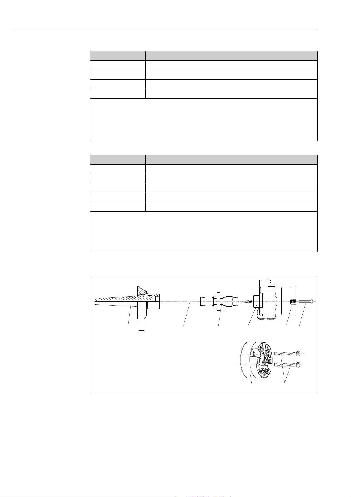
Fig. 2: Head transmitter mounting (three versions)
Item A Mounting in a terminal head (terminal head as per DIN EN50446, flat face)
1Terminal head
2 Circlips
3Insert
4 Connection wires
5 Head transmitter
6 Mounting springs
7Mounting screws
8 Terminal head cover
9Cable entry
Procedure:
1. Open the terminal head cover (8).
2. Guide the connection wires (4) of the insert (3) through the middle hole in the head transmitter (5).
3. Fit the mounting springs (6) onto the mounting screws (7).
4. Guide the mounting screws (7) through the lateral bores of the head transmitter and the insert (3). Then fix
both mounting screws in position with the circlips (2).
5. Then screw down the head transmitter (5) to the insert (3) in the terminal head.
6. After wiring (see section 4), close the terminal head cover (8) back on tight.
Endress+Hauser 9
Page 10
Installation instructions TMT85
1
234 5
6
5
6
Item B Mounting in a field housing
1 Field housing cover
2 Mounting screws with springs
3 Head transmitter
4 Field housing
Procedure:
1. Open the cover (1) of the field housing (4).
2. Guide the mounting screws (2) through the lateral bores of the head transmitter (3).
3. Screw the head transmitter to the field housing.
4. When wiring is complete (see section 4), screw the field housing cover (1) back on.
Item C Mounting on DIN rail as per IEC 60715
1 Mounting screws with springs
2 Head transmitter
3 Circlips
4DIN rail clip
5DIN rail
Procedure:
1. Press the DIN rail clip (4) onto the DIN rail (5) until it engages.
2. Fit the mounting springs onto the mounting screws (1) and guide them through the lateral bores of the head
transmitter (2). Then fix both mounting screws in position with the circlips (3).
3. Screw the head transmitter (2) to the DIN rail clip (4).
3.3.2 Mounting typical of North America
A0008520
Fig. 3: Head transmitter mounting
1: Thermowell
2: Insert
3: Adapter, threaded joint
4: Terminal head
5: Head transmitter
6: Mounting screws
10 Endress+Hauser
Page 11
TMT85 Installation instructions
NOTICE
Thermometer design with thermocouples or RTD sensors and head transmitter
→ å 3)
(
• Fit the thermowell (item 1) on the process pipe or the container wall. Secure the
thermowell according to the instructions before the process pressure is applied.
• Fit the necessary neck tube nipples and adapter (item 3) on the thermowell.
• Make sure sealing rings are installed if such rings are needed for harsh environmental
conditions or special regulations.
• Guide the mounting screws (item 6) through the lateral bores of the head transmitter
(item 7).
• Position the head transmitter (item 5) in the terminal head (item 4) in such a way that the
bus cable (terminals 1 and 2) point to the cable entry.
• Using a screwdriver, screw down the head transmitter (item 5) in the terminal head (item
4).
• Guide the connection wires of the insert (item 3) through the lower cable entry of the
terminal head (item 4) and through the middle hole in the head transmitter (item 5). Wire
the connection wires and transmitter (see Section 4) with one another.
• Screw the terminal head (item 4), with the integrated and wired head transmitter, onto
the ready-mounted nipple and adapter (item 3).
Requirements for explosion protection
‣ Once the wiring is completed, screw the terminal head cover back on. The terminal head
cover must be secured properly.
3.3.3 Mounting the display
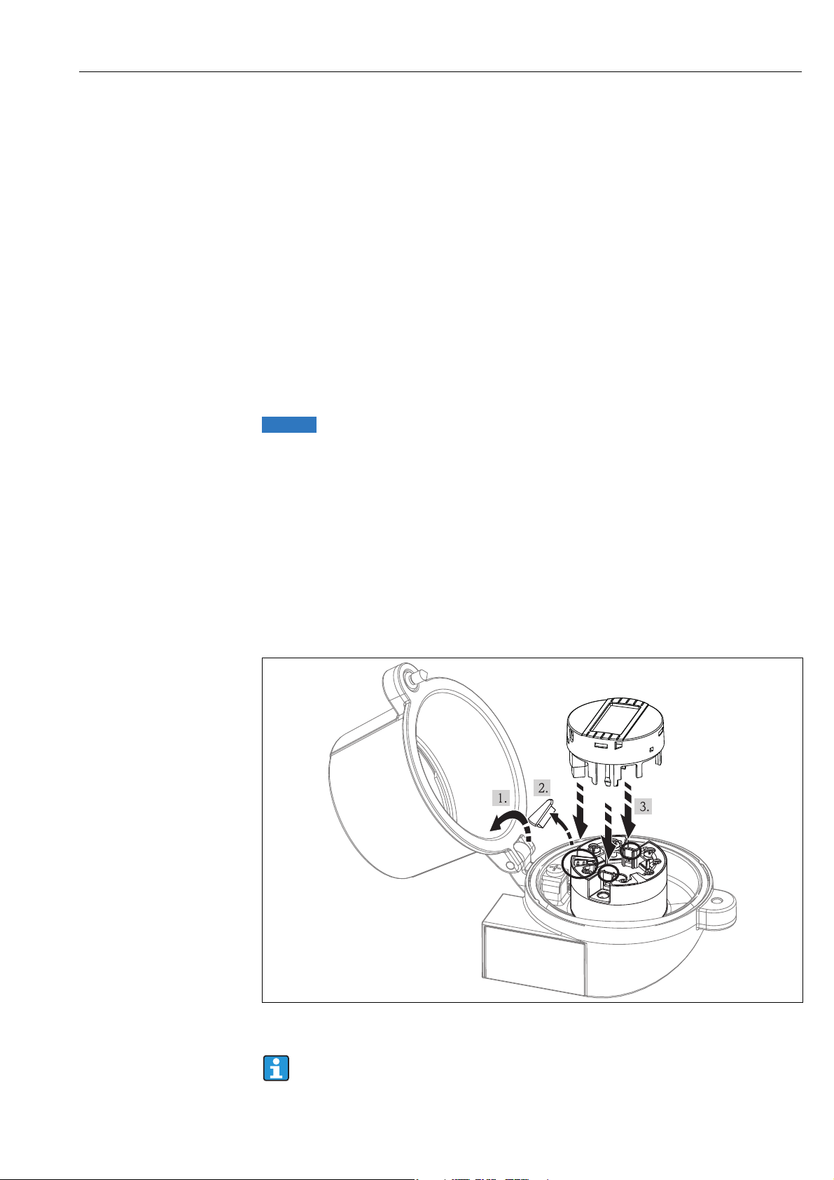
1. Remove the screw from the terminal head. Open the terminal head cap (1).
2. Remove the cover of the display connection (2). Plug the display module onto the
mounted and wired head transmitter. The mounting pins (3) must snap securely into
the head transmitter.
3. After mounting the display, close the terminal head cap and refit the screw.
A0009852
Fig. 4: Mounting the display
The display can only used with the suitable Endress+Hauser terminal heads TA30
and caps with display window.
Endress+Hauser 11
Page 12

Installation instructions TMT85
3.4 Post-installation check
After installing the device, always run the following final checks:
Device condition and specifications Notes
Is the device visibly damaged (visual check)? -
Does the device comply to the measurement point specifications, such as
ambient temperature, measurement range etc.?
See chapter 10 "Technical data"
12 Endress+Hauser
Page 13
TMT85 Wiring
NOTICE
-
+
+
1
-
2
7
6
5
4
3
1
2
7
6
5
4
3
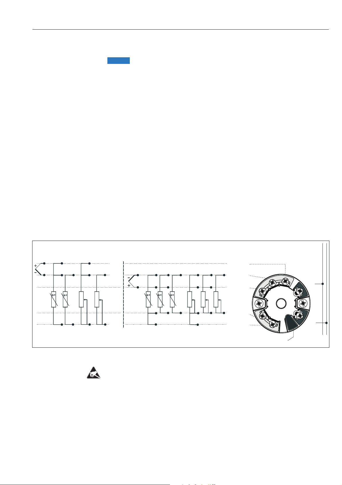
Sensor input 2
Sensor input 1
Bus connection
and supply voltage
Display connection/
service interface
TC, mV
RTD, 4-, 3- and 2-wire:Ω
RTD, 3- and 2-wire:Ω
TC, mV
white
red
red
white
white
red
red
(black)
(yellow)
(black)
4 Wiring
Electronic parts may be damaged
‣ Switch off power supply before installing or connecting the device. Failure to observe this
may result in destruction of parts of the electronics.
‣ When installing Ex-approved devices in a hazardous area please take special note of the
instructions and connection schematics in the respective Ex documentation added to
these Operating Instructions. The local E+H representative is available for assistance if
required.
‣ The 4-pin post connector is only designed for connecting the associated display.
Connecting other devices can destroy parts of the electronics.
For wiring a mounted head transmitter, proceed as follows:
1. Open the cable gland and the housing cover on the terminal head or the field housing.
2. Feed the cables through the opening in the cable gland.
3. Connect the cables as shown in → å 5. If the head transmitter is fitted with spring
terminals, please pay particular attention to → Chap. 4.2.1.
4. Retighten the cable gland and close the housing cover.
5. In order to avoid connection errors always take note of the hints given in the section
connection check!
4.1 Quick wiring guide
Terminal assignment
Fig. 5: Wiring the head transmitter
ESD - electrostatic discharge
Protect the terminals from electrostatic discharge. Failure to observe this may result in
Endress+Hauser 13
destruction or malfunction of parts of the electronics.
A0007285-EN
Page 14
Wiring TMT85
ABCD
4.2 Connecting the sensor cables
When connecting 2 sensors ensure that there is no galvanic connection between the
sensors (e.g. caused by sensor elements that are not isolated from the thermowell).
The resulting equalizing currents distort the measurements considerably. In this
situation, the sensors have to be galvanically isolated from one another by connecting each sensor separately to a transmitter. The device provides sufficient galvanic
isolation (> 2 kV AC) between the input and output.
Please refer to → å 5 for the terminal assignment of the sensor connections.
The following connection combinations are possible when both sensor inputs are assigned:
Sensor input 1
Sensor
input 2
RTD or resistance
transmitter, two-wire
RTD or resistance
transmitter, threewire
RTD or resistance
transmitter, four-wire
Thermocouple (TC),
voltage transmitter
RTD or
resistance
transmitter,
two-wire
  - Â
  - Â
----
   Â
RTD or
resistance
transmitter,
three-wire
RTD or
resistance
transmitter,
four-wire
Thermocouple
(TC), voltage
transmitter
4.2.1 Connecting to spring terminals
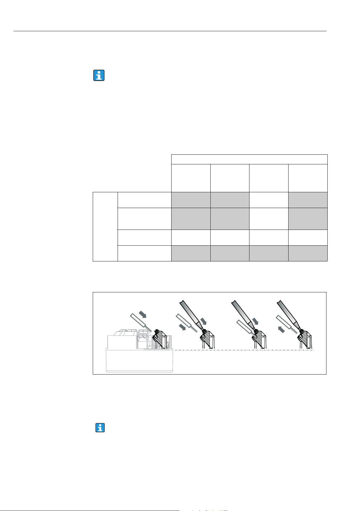
Fig. 6: Spring terminal connection
A Insert wire end (solid wire or wire with ferrule)
B Insert wire end (fine-strand wire without ferrule)
C Release wire end with tool
D Remove wire end
When connecting flexible cables and spring terminals, it is not recommended to use ferrules.
A0008322
14 Endress+Hauser
Page 15

TMT85 Wiring
Procedure:
Item A, solid wire: 1. Strip wire end. Minimum stripping length = 10 mm (0.39 in)
2. Insert the wire end into the terminal (A).
3. Check the connection by pulling on the wire lightly. Repeat from
step 1 if necessary.
Item B, fine-strand wire without ferrule:1. Strip wire end. Minimum stripping length = 10 mm (0.39 in)
2. Operate lever opener with tool (B).
3. Insert the wire end into the terminal (B).
4. Release lever opener.
5. Check the connection by pulling on the wire lightly. Repeat from
step 1 if necessary.
Item C and D, releasing the connection: 1. Operate lever opener with tool (C).
2. Remove wire from terminal (D).
3. Release lever opener.
4.3 FOUNDATION Fieldbus™ cable specification
4.3.1 Cable type
Twin-core cables are required for connecting the device to the FOUNDATION Fieldbus™ H1.
Following IEC 61158-2 (MBP), four different cable types (A, B, C, D) can be used with the
FOUNDATION Fieldbus™, only two of which (cable types A and B) are shielded.
• Cable types A or B are particularly preferable for new installations. Only these types have
cable shielding that guarantees adequate protection from electromagnetic interference
and thus the most reliable data transfer. In the case of cable type B, several field buses
(same degree of protection) may be operated in one cable. No other circuits are permissible
in the same cable.
• Practical experience has shown that cable types C and D should not be used due to the lack
of shielding, since the freedom from interference generally does not meet the
requirements described in the standard.
The electrical data of the fieldbus cable have not been specified but determine important
characteristics of the design of the fieldbus, such as distances bridged, number of users,
electromagnetic compatibility, etc.
Type A Type B
Cable structure Twisted pair, shielded One or more twisted pairs, fully
shielded
Wire size 0.8 mm
Loop-resistance (direct current) 44 Ω/km 112 Ω/km
Characteristic impedance at
31.25 kHz
Attenuation constant at 39 kHz 3 dB/km 5 dB/km
Capacitive asymmetry 2 nF/km 2 nF/km
2
(AWG 18) 0.32 mm2 (AWG 22)
100 Ω ± 20% 100 Ω ± 30%
Endress+Hauser 15
Page 16

Wiring TMT85
Type A Type B
Envelope delay distortion (7.9 to
39 kHz)
Shield coverage 90% *
Max. cable length (incl. spurs >1 m)1900 m (6233 ft) 1200 m (3937 ft)
* Not specified
1.7 ms/km *
Suitable fieldbus cables (type A) from various manufacturers for non-hazardous areas are
listed below:
• Siemens: 6XV1 830-5BH10
• Belden: 3076F
• Kerpen: CeL-PE/OSCR/PVC/FRLA FB-02YS(ST)YFL
4.3.2 Maximum overall cable length
The maximum network expansion depends on the type of protection and the cable
specifications. The overall cable length combines the length of the main cable and the length
of all spurs (>1 m/3.28 ft). Note the following points:
• The maximum permissible overall cable length depends on the cable type used.
• If repeaters are used, the maximum permissible cable length is doubled. A maximum of
three repeaters are permitted between user and master.
4.3.3 Maximum spur length
The line between the distribution box and field device is described as a spur.
In the case of non-Ex applications, the max. length of a spur depends on the number of spurs
(>1 m/3.28 ft):
Number of spurs 1 to 12 13 to 14 15 to 18 19 to 24 25 to 32
Max. length per spur 120 m (393
ft)
90 m (295
ft)
60 m (196
ft)
30 m (98 ft) 1 m (3.28 ft)
4.3.4 Number of field devices
In accordance with IEC 61158-2 (MBP), a maximum of 32 field devices can be connected per
fieldbus segment. However, this number is restricted under certain conditions (explosion
protection, bus power option, field device current consumption). A maximum of four field
devices can be connected to a spur.
4.3.5 Shielding and grounding
Optimum electromagnetic compatibility (EMC) of the fieldbus system can only be
guaranteed if the system components and, in particular, the lines are shielded and the shield
forms as complete a cover as possible. A shield coverage of 90% is ideal.
• To ensure an EMC protective effect, connect the shield as often as possible to the reference
ground.
• For reasons of explosion protection, you should refrain from grounding however.
16 Endress+Hauser
Page 17

TMT85 Wiring
NOTICE
To comply with both requirements, the FOUNDATION Fieldbus™ basically allows three
different types of shielding:
• Shielding at both ends
• Shielding at one end on the feed side with capacitance connection to the field device
• Shielding at one end on the feed side
Experience shows that the best results with regard to EMC are achieved in most cases in
installations with one-sided shielding. Appropriate measures with regard to input wiring
must be taken to allow unrestricted operation when EMC interference is present. These
measures have been taken into account for this device. Operation in the event of disturbance
variables as per NAMUR NE21 is possible with one-sided shielding.
Where applicable, national installation regulations and guidelines must be observed during
the installation!
Where there are large differences in potential between the individual grounding points, only
one point of the shielding is connected directly with the reference ground. In systems
without potential equalization, therefore, cable shielding of fieldbus systems should only be
grounded on one side, for example at the fieldbus supply unit or at safety barriers, → å 7
A0008770
Fig. 7: Shielding and one-sided grounding of the fieldbus cable shielding
1 Supply unit
2 Distribution box (T-box)
3Bus terminator
4 Grounding point for fieldbus cable shielding
5 Optional grounding of the field device, isolated from cable shielding.
If the shielding of the cable is grounded at more than one point in systems without
potential matching, power supply frequency equalizing currents can occur that damage
the bus cable or shielding or have serious effect on signal transmission.
‣ In such cases the shielding of the fieldbus cable is to be grounded on only one side, i.e. it
must not be connected to the ground terminal of the housing (terminal head, field
housing). The shield that is not connected should be insulated!
4.3.6 Bus termination
The start and end of each fieldbus segment are always to be terminated with a bus
terminator. With various junction boxes (non-Ex), the bus termination can be activated via
a switch. If this is not the case, a separate bus terminator must be installed. Note the
following points in addition:
• In the case of a branched bus segment, the device furthest from the segment coupler
represents the end of the bus.
• If the fieldbus is extended with a repeater, then the extension must also be terminated at
both ends.
Endress+Hauser 17
Page 18

Wiring TMT85
NOTICE
4.3.7 Further information
General information and further pointers on wiring can be found on www.fieldbus.org, the
Web site of the Fieldbus Foundation or in the Operating Instructions "FOUNDATION
Fieldbus™ Overview" which can also be found on the CD-ROM. (Additional sources: →
www.endress.de → Download).
4.4 Connecting the measuring unit
Devices can be connected to the FOUNDATION Fieldbus™ in two ways:
• Connection via conventional cable gland → Chap. 4.4.1
• Connection via fieldbus connector (optional, can be purchased as an accessory)
→ Chap. 4.4.2
Risk of damaging
‣ Switch off power supply before installing or connecting the head transmitter. Failure to
observe this may result in destruction of parts of the electronics.
‣ Grounding via one of the grounding screws (terminal head, field housing) is
recommended.
‣ If the shielding of the fieldbus cable is grounded at more than one point in systems
without additional potential matching, power supply frequency equalizing currents can
occur that damage the cable or the shielding. In such cases the shielding of the fieldbus
cable is to be grounded on only one side, i.e. it must not be connected to the ground
terminal of the housing (terminal head, field housing). The shield that is not connected
should be insulated!
‣ We recommend that the fieldbus not be looped using conventional cable glands. If you
later replace even just one measuring device, the bus communication will have to be
interrupted.
4.4.1 Cable glands or entries
Please also observe the general procedure on → ä 13.
A0008284
Fig. 8: Connection to the FOUNDATION Fieldbus™ fieldbus cable - installed in the field housing on the left, and in the terminal
1 FF terminals - fieldbus communication and power supply
2 Inner ground terminal
3Outer ground terminal
4 Shielded fieldbus cable (FOUNDATION Fieldbus™)
head on the right
• The terminals for the fieldbus connection (1+ and 2-) are not polarity sensitive.
• Conductor cross-section:
2
max. 2.5 mm
max. 1.5 mm
for screw terminals
2
for spring terminals
• A shielded cable must be used for the connection.
18 Endress+Hauser
Page 19

TMT85 Wiring
190 mm (7.48 in)
26.5 mm
(1.040 in)
M20x1.5 /
NPT 1/2”
7/8-16 UNC
A
B
4
1
2
C
3
5
6
4.4.2 Fieldbus connector
Optionally, a fieldbus connector can be screwed into the terminal head or field housing
instead of a cable gland. Fieldbus connectors can be ordered from Endress+Hauser as an
accessory (see Section 8 'Accessories').
The connection technology of FOUNDATION Fieldbus™ allows measuring devices to be
connected to the fieldbus via uniform mechanical connections such as T-boxes, junction
boxes, etc.
This connection technology using prefabricated distribution modules and plug-in connectors
offers substantial advantages over conventional wiring:
• Field devices can be removed, replaced or added at any time during normal operation.
Communication is not interrupted.
• Installation and maintenance are significantly easier.
• Existing cable infrastructures can be used and expanded instantly, e.g. when constructing
new star distributors using 4-channel or 8-channel distribution modules.
A0008283
Fig. 9: Connectors for connecting to the FOUNDATION Fieldbus™
A Fieldbus connector (pin assignment/color codes)
– 1 Blue wire: FF– (terminal 2)
– 2 Brown wire: FF+ (terminal 1)
– 3 Gray wire: shielding
– 4 Green/yellow wire: ground
– 5 Positioning tappet
– 6 7/8" UNC thread
B Terminal head thermometer
C Connector at the housing (male)
Connector technical data:
Wire cross-section 4 x 0.8 mm2
Connection thread M20 x 1.5 / NPT ½"
Degree of protection IP 67 as per DIN 40 050 IEC 529
Contact surface CuZn, gold-plated
Housing material 1.4401 (316)
Flammability V - 2 as per UL - 94
Ambient temperature –40 to +105 °C (–40 to +221 °F)
Current carrying capacity 9 A
Rated voltage max. 600 V
Contact resistance ≤ 5 mΩ
Insulation resistance ≥ 109 Ω
Endress+Hauser 19
Page 20

Wiring TMT85
4.5 Post-connection check
After the electrical installation of the device, always perform the following final checks:
Device condition and specifications Notes
Are the measuring device or the cables damaged (visual check)? -
Electrical connection Notes
Does the supply voltage match the specifications on the nameplate? 9 to 32 V DC
Do the cables used comply with the specifications? Fieldbus cable, → ä 15
Sensor cable, → ä 14
Do the cables have adequate strain relief? -
Are the power supply and signal cables correctly connected? → Chap. 4.1
Are all the screw terminals well tightened and have the connections of the
spring terminals been checked?
Are all the cable entries installed, tightened and sealed?
Cable run with "water trap"?
Are all the housing covers installed and tightened?
Electrical connection of FOUNDATION Fieldbus™ Notes
Are all the connecting components (T-boxes, junction boxes, connectors,
etc.) connected with each other correctly?
Has each fieldbus segment been terminated at both ends with a bus
terminator?
Has the max. length of the fieldbus cable been observed in accordance with
the FOUNDATION Fieldbus™ specifications?
FOUNDATION Fieldbus™ specifications?
Is the fieldbus cable fully shielded (90%) and correctly grounded?
→ ä 14
-
-
→ ä 15Has the max. length of the spurs been observed in accordance with the
20 Endress+Hauser
Page 21
TMT85 Operation
5Operation
5.1 Quick operation guide
Display and operating elements are only available locally if the head transmitter was
ordered with a display unit!
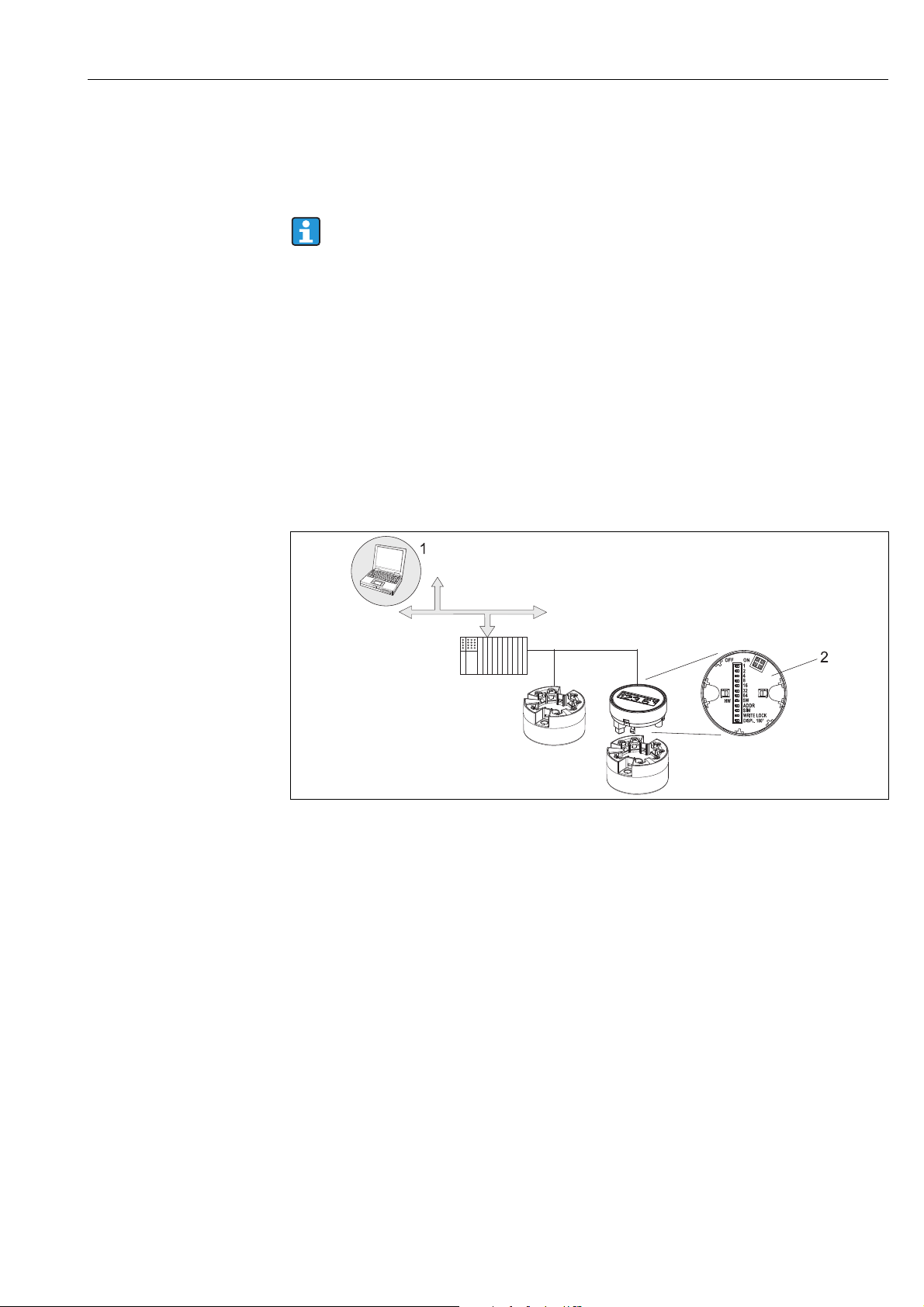
You have a number of options for configuring and commissioning the device:
1. Configuration programs
The configuration of FF functions and device-specific parameters is done via the fieldbus
interface. You can obtain special configuration and operating programs from various
manufacturers for these purposes.→ ä 26
2. Miniature switches (DIP switches) for diverse hardware settings, optional
You can make the following hardware settings for the FOUNDATION Fieldbus™ interface
using miniature switches (DIP switches) on the rear of the optional display → ä 26:
• Enabling/disabling the simulation mode in the Analog Input function block
• Switching the hardware write protection on/off
• Switching (turning) the display 180 °
Fig. 10: Head transmitter operating options
1 Configuration/operating programs for operation via FOUNDATION Fieldbus™ (Foundation Fieldbus functions, device
parameter)
2 DIP switch for hardware settings is on the rear of the optional display (write protection, simulation mode)
A0008323
Endress+Hauser 21
Page 22

Operation TMT85
1
2
3
4
5
6
7
5.2 Display and operating elements
5.2.1 Display
A0008549
Fig. 11: Optional LC display of the head transmitter
5.2.2 Display symbols
Item
Function Description
No.
1 Displays the TAG TAG, 32 characters long.
2 'Communication' symbol The communication symbol appears when read and
3 Unit display Unit display for the measured value displayed.
4 Measured value display Displays the current measured value.
5 Channel display C1 or C2, P1, S1, RJ e.g. S1 for a measured value from sensor1.
6 'Configuration locked' symbol The 'configuration locked' symbol appears when
7 Warning or error message If a warning occurs, the display alternates between the
write-accessing via the FOUNDATION Fieldbus™
protocol.
configuration is locked via the hardware.
measured value and the warning code. If an error
occurs, the display alternates between the error code
and "- - - -" (no valid measured value available), (see
Section 9.2 'Status messages'.
5.2.3 Local operation
You can make hardware settings for the FOUNDATION Fieldbus™ interface using miniature
switches (DIP switches) on the rear of the optional display → ä 26:
5.3 FOUNDATION Fieldbus™ technology
The FOUNDATION Fieldbus™ (FF) is a purely digital, serial communication system that
connects fieldbus devices (sensors, actuators), automation and process control systems with
each other. As a local communications network (LAN) for field devices the FF was primarily
designed for the requirements of process technology. The FF thus forms the basic network
throughout the hierarchy of a communication system.
Please refer to Operating Instructions BA 013S/04/en “FOUNDATION Fieldbus Overview:
Installation and Commissioning Guidelines” for configuration information.
22 Endress+Hauser
Page 23
TMT85 Operation
0 - 10 bar
0 - 10 bar
Visualisation and monitoring
e. g. P View, FieldCare
and diagnostic software
High speed Ethernet
(HSE) 100 Mbit/s
32 devices per segment
Field controller
linking
device
ENDRESS+HAUSER
ENDRESS+HAUSER
linking
device
linking
device
H1
31.25 kbit/s
H1 IEC 61158-2
H1 FISCO
Measuring point with
installed TMT85
Measuring point with
installed TMT85
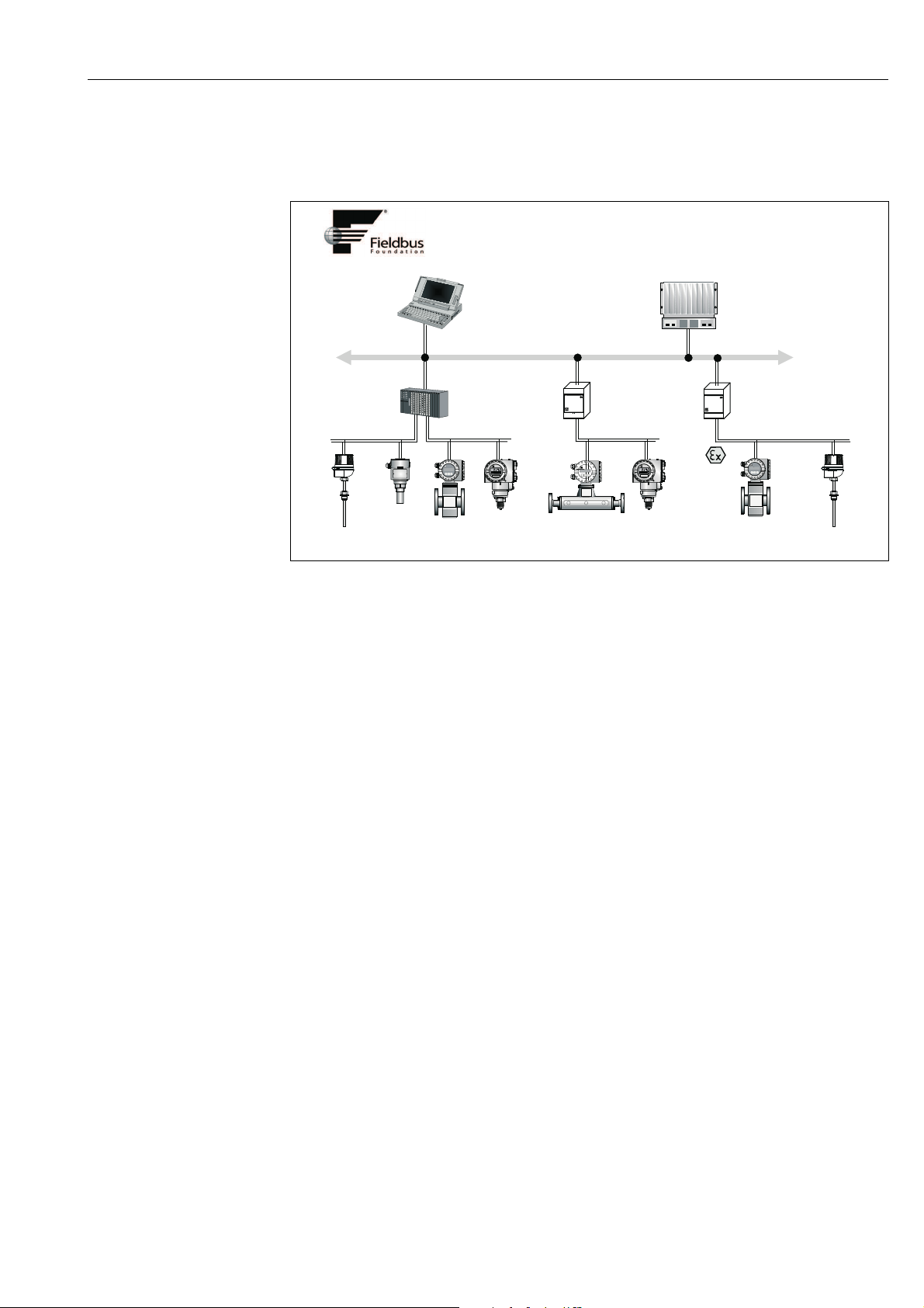
5.3.1 System architecture
The following figure shows an example of a FOUNDATION Fieldbus™ network with the
associated components.
Fig. 12: System integration via FOUNDATION Fieldbus™
HSE = High Speed Ethernet, H1 = FOUNDATION Fieldbus-H1
The following system connection options are possible:
– A linking device can be used to connect to higher ranking fieldbus protocols (e.g. to the High Speed
– A H1 card is required for direct connection to a process control system.
– System inputs are available directly for H1 (HSE).
The system architecture of the FOUNDATION Fieldbus™ can be divided into two
subnetworks:
H1 bus system:
In the field, fieldbus devices are connected only via the slower H1 bus system that is specified
following IEC 61158-2. The H1 bus system allows simultaneous feed to the field devices and
data transfer on the two-wire line.
The following points describe some important characteristics of the H1 bus system:
• All fieldbus devices are powered via the H1 bus. Like the fieldbus devices, the power supply
• One of the most common network structures is the line structure. Star, tree or mixed
• The bus connection to the individual fieldbus devices is achieved by means of a T-
• The number of connected fieldbus devices depends on various factors, such as use in
• If using fieldbus devices in a hazardous area, the H1 bus must be equipped with an
• A bus terminator is required at each end of the bus segment.
A0007668-EN
Ethernet - HSE) (Control Net)
is connected in parallel to the bus line. Devices requiring external power must use a
separate power supply.
network structures are also possible using connecting components (junction boxes).
connector or via a spur. This has the advantage that individual fieldbus devices can be
connected or disconnected without interrupting the bus or the bus communication.
hazardous areas, length of spur, cable types, current consumption of field devices etc. (see
→ ä 15).
intrinsically safe barrier before the transition to the hazardous area.
Endress+Hauser 23
High Speed Ethernet (HSE):
The superior bus system is realized via the High Speed Ethernet (HSE) with a transmission
rate of max. 100 MBit/s. This serves as the 'backbone' (basic network) between various local
sub-networks and/or where there is a large number of network users.
Page 24

Operation TMT85
5.3.2 Link Active Scheduler (LAS)
The FOUNDATION Fieldbus™ works according to the 'producer-consumer' relationship.
This provides various advantages.
Data can be directly exchanged between field devices, e.g. a sensor and an actuating valve.
Each bus user ’publishes’ its data on the bus and all the bus users configured accordingly
obtain this data. Publication of this data is carried out by a ’bus administrator’ known as the
’Link Active Scheduler’, which controls the sequence of bus communication centrally. The
LAS organizes all the bus activities and sends appropriate commands to the individual field
devices.
Other tasks of the LAS are:
• Recognition and reporting of newly connected devices.
• Reporting the removal of devices no longer communicating with the fieldbus.
• Keeping the ’Live List’. This list, in which all the fieldbus users are recorded, is checked by
the LAS regularly. If devices are logged on or logged off, the "Live List" is updated and sent
immediately to all the devices.
• Requesting process data from the field devices in accordance with a fixed schedule.
• Allocation of send rights (tokens) to devices between the untimed data transfer.
The LAS can be run redundantly, i.e. it exists both in the process control system and in the
field device. If one LAS fails, the other LAS can accurately take over communication. Through
precise timing of the bus communication via the LAS, the FF can run exact processes at
regular intervals.
Fi eld bus devi ces , suc h as thi s he ad t ran smi tte r, wh ich can tak e ov er t he L AS fu nct ion
in the event of failure of the primary master, are called 'Link Masters'. In contrast,
'Basic Devices' can only receive signals and send them to the central process control
system. The LAS function is deactivated in this head transmitter when the unit is
delivered.
5.3.3 Data transfer
We distinguish between two types of data transfer:
• Scheduled data transfer (cyclic): all time-critical process data (i.e. continuous
measurement or actuating signals) are transferred and processed in accordance with a
fixed schedule.
• Unscheduled data transfer (acyclic): device parameters that are not time-critical for the
process and diagnosis information are only transferred to the fieldbus when needed. This
data transfer is always carried out in the intervals between timed
communication.
5.3.4 Device ID, addressing
Within the FF network, each fieldbus device is identified by a unique device ID (DEVICE_ID).
The fieldbus host system (LAS) automatically gives the network address for this to the field
device. The network address is the address that the fieldbus currently uses.
The FOUNDATION Fieldbus™ uses addresses between 0 and 255:
• Groups/DLL: 0 to 15
• Devices in operation: 20 to 35
• Reserve devices: 232 to 247
• Offline/substitute devices: 248 to 251
The field device tag name (PD_TAG) is given to the device in question during commissioning
(see → ä 29). It remains stored in the device even during a supply voltage failure.
24 Endress+Hauser
Page 25

TMT85 Operation
5.3.5 Function blocks
The FOUNDATION Fieldbus™ uses predefined function blocks to describe the functions of a
device and to specify uniform data access. The function blocks implemented in each fieldbus
device provide information on the tasks which a device can accept in the whole of the
automation strategy.
In the case of sensors these are typically the following blocks:
• ’Analog Input’ or
• ’Discrete Input’ (digital input)
Actuating valves normally have the function blocks:
• ’Analog Output’ or
• ’Discrete Output’ (digital output)
For control tasks there are the blocks:
• PD controller or
•PID controller
More information on this can be found from Section 11 onwards.
5.3.6 Fieldbus based process control
With the FOUNDATION Fieldbus™ field devices can carry out simple process control
functions themselves, thereby relieving pressure on the superior process control system.
Here the Link Active Scheduler (LAS) coordinates data exchange between the sensor and
controller and makes sure that two field devices cannot access the bus at the same time. To
do this, configuration software such as the NI-FBUS Configurator from National Instruments
is used to connect the various function blocks to the desired control strategy – generally
graphically (→ ä 29).
5.3.7 Device description
For commissioning, diagnosis and configuration, make sure that process control systems or
superior configuration systems can access all device data and that the operating structure is
uniform.
The device-specific information required for this is stored as so-called device description
data in special files (the ’Device Description’- DD). This enables the device data to be
interpreted and shown via the configuration program. The DD is thus a kind of ’device
driver’.
On the other hand, a CFF file (CFF = Common File Format) is required for the network
configuration in the OFF-line mode.
These files can be acquired as follows:
– Free of charge via the Internet: www.endress.com
– Via the Fieldbus Foundation Organization: www.fieldbus.org
Endress+Hauser 25
Page 26

Operation TMT85
5.4 Configuration of the transmitter and FF functions
The FF communication system will only function properly if correctly configured. You can
obtain special configuration and operating programs from various manufacturers for the
configuration.
These can be used for configuring both the FF functions and all of the device-specific
parameters. The predefined function blocks allow uniform access to all the network and
fieldbus device data.
A detailed step-by-step description of the procedure for commissioning the FF functions is
given on → ä 29 together with information on configuring device-specific parameters.
System files
You require the following files for commissioning and configuring the network:
• Commissioning → device description (DD: *.sym, *.ffo, *.sy5, *.ff5)
•Network configuration → CFF file (Common File Format)
5.5 Hardware settings (optional)
DIP switches on the rear of the display are used to enable and disable hardware write
protection and the simulation mode (for the Analog Input Block), and to switch (turn) the
display 180°. When write protection is active, parameters cannot be modified. The current
write protection status is displayed in the WRITE_LOCK parameter (Resource Block, see
Section 11).
The simulation mode via the hardware setting must be changed before the software setting.
The display can optionally be ordered with the transmitter, or as an accessory for subsequent
mounting (see Section 8).
ESD - electrostatic discharge
Protect the terminals from electrostatic discharge. Failure to observe this may result in
destruction or malfunction of parts of the electronics.
To set the DIP switches, proceed as follows:
1. Open the cover of the terminal head or field housing.
2. Remove the attached display from the head transmitter.
3. Configure the DIP switch on the rear of the display accordingly. Switch to ON = function
enabled, switch to OFF = function disabled.
4. Fit the display onto the head transmitter in the correct position. The head transmitter
accepts the settings within one second.
5. Secure the cover back onto the terminal head or field housing.
The DIP switch settings are no longer valid as soon as the display is removed from
the head transmitter.
A0008326
Fig. 13: Hardware settings via DIP switches
1 Connection to head transmitter
2 DIP switch (1 - 7, SW/HW and ADDR ACTIVE), no function
3 DIP switch (SIM = simulation mode; WRITE LOCK = write protection; DISPL. 180° = switch (turn) the display 180°)
26 Endress+Hauser
Page 27

TMT85 Commissioning
6 Commissioning
6.1 Function check
Before commissioning the measurement point make sure that all final checks have been
carried out:
• Checklist “Post-installation check”→ ä 12
• Checklist “Post-connection check”→ ä 20
The FOUNDATION Fieldbus interface's technical data must be maintained in
accordance with IEC 61158-2 (MBP).
The bus voltage of 9 to 32 V and the current consumption of approx. 11 mA at the
measuring device can be checked using a normal multimeter.
6.2 Switching on the measuring device
Once the final checks have been successfully completed, it is time to switch on the supply
voltage. The head transmitter performs a number of internal test functions after power-up.
As this procedure progresses, the following sequence of messages appears on the display:
Step Display
1 Display and firmware version (FW)
2Company logo
3 Device name as well as the firmware, hardware version and device revision of the
head transmitter
4 Displays sensor configuration
5 Current measured value or
Current status message
If the switch-on procedure fails, the appropriate status message is displayed,
depending on the cause. A detailed list of the status messages, as well as the
measures for troubleshooting, can be found in section 9, 'Troubleshooting'.
The device is operational after approx. 8 seconds and the attached display after approx. 16
seconds. Normal measuring mode commences as soon as the switch-on procedure is
completed. Various measured values and/or status values appear on the display.
6.3 Commissioning
Note the following points:
• The files required for commissioning and network configuration can be obtained as
described on → ä 25.
• In the case of the FOUNDATION Fieldbus™, the device is identified in the host or
configuration system by means of the device ID (DEVICE_ID). The DEVICE_ID is a
combination of the manufacturer ID, device type and device serial number. It is unique and
can never be assigned twice. The DEVICE_ID of the device is composed as follows:
DEVICE_ID = 452B4810CE-XXXXXXXXXXX
452B48 = Endress+Hauser
10CE = TMT85
XXXXXXXXXXX = device serial number (11-digit)
• For quick and reliable head transmitter configuration, a wide range of configuration
wizards are available to guide the user through the configuration of the most important
parameters of the Transducer Blocks. Please refer to the Operating Instructions of your
operating and configuration software.
Endress+Hauser 27
Page 28

Commissioning TMT85
The following wizards are available:
Configuration wizards
Name Block Description
Quick setup Sensor Transducer Configuration of the sensor input with sensor-relevant data.
Quick setup Display Transducer Menu-guided configuration of the display unit.
Set to OOS mode Resource, Sensor
Set to auto mode Resource, Sensor
Restart Resource Device restart with various options as to which parameters are
Sensor drift monitoring
configuration
Calc.- wizard for 2-wire
compensation value
Set all TRD to OOS mode All transducer
Set all TRD to auto mode All transducer
Show recommended
action
Calibration wizards
User sensor trim
configuration
Factory trim settings Sensor Transducer Reset scaling to the "Factory Standard Trim" (see section 11).
RTD-Platin configuration
Call.-Van Dusen
RTD-Copper
configuration
RTD-Nickel configuration Sensor Transducer Entry of coefficients for polynom nickel.
Transducer,
Display
Transducer,
AdvDiagnostic
Transducer, AI, PID
and ISEL
Transducer,
Display
Transducer,
AdvDiagnostic
Transducer, AI, PID
and ISEL
AdvDiagnostic
Transducer
Sensor Transducer Calculation of the conductor resistance for two-wire
blocks
blocks
Resource Shows the recommended action for the currently active
Sensor Transducer Menu guidance for linear scaling (offset + slope) to adapt the
Sensor Transducer Entry of Callendar-Van-Dusen coefficients.
Sensor Transducer Entry of coefficients for polynom copper.
Setup of the single block to mode "Out Of Service"
Setup of the single block to mode "Auto"
to be reset to default values.
Settings for drift or differential monitoring with 2 connected
sensors.
compensation.
Sets all transducer blocks to mode "Out Of Service" at the same
time
Sets all transducer blocks to mode "Auto" at the same time
condition
measuring point to the process (see section 11).
28 Endress+Hauser
Page 29

TMT85 Commissioning
6.3.1 Initial commissioning
The following description takes you step-by-step through commissioning the device and all
the necessary configurations for the FOUNDATION Fieldbus™:
1. Open the configuration program.
2. Load the device description files or the CFF file into the host system or the configuration
program. Make sure you are using the right system files (see Section 5.4).
3. Note the DEVICE_ID on the device nameplate for identification in the process control
system (see Section 2 'Identification').
4. Switch the device on.→ ä 27
The first time you establish a connection, the device reacts as follows in the
configuration system:
– EH_TMT85_xxxxxxxxxxx (tag name PD-TAG)
– 452B4810CE-xxxxxxxxxxx (DEVICE_ID)
– Block structure:
Display text (xxx... = serial number) Base index Description
RS_xxxxxxxxxxx 400 Resource Block
TB_S1_xxxxxxxxxxx 500 Transducer Block temperature sensor 1
TB_S2_xxxxxxxxxxx 600 Transducer Block temperature sensor 2
TB_DISP_xxxxxxxxxxx 700 Transducer Block “Display”
TB_ADVDIAG_xxxxxxxxxxx 800 Transducer Block “Advanced Diagnostic”
AI_1_ xxxxxxxxxxx 900 Analog Input function block 1
AI_2_ xxxxxxxxxxx 1000 Analog Input function block 2
AI_3_ xxxxxxxxxxx 1100 Analog Input function block 3
PID_ xxxxxxxxxxx 1200 PID function block
ISEL_xxxxxxxxxxx 1300 Input Selector function block
The device is delivered from the factory with the bus address “247” and is thus in the address range between 232 and 247 reserved for readdressing field devices. A lower bus address should be assigned to the
device for commissioning.
5. Using the DEVICE_ID noted, identify the field device and assign the desired tag name
(PD_TAG) to the fieldbus device in question.
Factory setting: EH_TMT85_xxxxxxxxxxx (xxx... = serial number).
Endress+Hauser 29
Page 30

Commissioning TMT85
A0019666
Fig. 14: Screen display in the configuration program “NI-FBUS Configurator” (National Instruments) after the connection has
1 Device designation in the Configurator (EH_TMT85_xxxxxxxxxxx = factory setting for tag name PD_TAG)
2 Block structure
been established
Configuring the "Resource Block" (base index 400)
6. Open the Resource Block.
7. When the device is delivered, the hardware write protection is disabled so the write
parameters can be accessed via the FF. Check the status via the WRITE_LOCK
parameter:
– Write protection enabled = LOCKED
– Write protection disabled = NOT LOCKED
Disable the write protection if necessary, → ä 26.
8. Enter the desired name for the block (optional).
Factory setting: RS_xxxxxxxxxxx
Set the operating mode in the MODE_BLK parameter group (TARGET parameter) to
AUTO.
Configuring the "Transducer Blocks"
The individual Transducer Blocks comprise various parameter groups arranged by devicespecific functions:
Temperature sensor 1 → Transducer Block “TB_S1_xxxxxxxxxxx” (base index:
500)
Temperature sensor 2 → Transducer Block “TB_S2_xxxxxxxxxxx” (base index:
600)
Onsite display functions → Transducer Block “TB_DISP_xxxxxxxxxxx” (base index: 700)
Advanced diagnostics → Transducer Block “TB_ADVDIAG_xxxxxxxxxx”
(base index: 800)
9. Enter the desired name for the block (optional). For factory settings, see the table
above. Set the operating mode in the MODE_BLK parameter group (TARGET
parameter) to AUTO.
30 Endress+Hauser
Page 31

TMT85 Commissioning
NOTICE
NOTICE
Configuring the "Analog Input function blocks"
The device has 2 x three Analog Input function blocks which can be assigned to the different
process variables as desired. The following section describes an example for the Analog
Input function block 1 (base index 900).
10. Enter the required name for the Analog Input function block (optional).
Factory setting: AI_1_ xxxxxxxxxxx
11. Open Analog Input function block 1.
12. Set the operating mode in the MODE_BLK parameter group (TARGET parameter) to
OOS, i.e. the block is out of service.
13. Use the CHANNEL parameter to select the process variable which should be used as the
input value for the function block algorithm (scaling and limit value monitoring
functions). The following settings are possible:
CHANNEL → Uninitialized
Primary Value 1
Primary Value 2
Sensor Value 1
Sensor Value 2
Device temperature
14. In the XD_SCALE parameter group, select the desired engineering unit as well as the
block input range for the process variable in question.
Faulty parameterization
‣Make sure that the engineering unit selected suits the measured variable of the
process variable chosen. Otherwise, the BLOCK_ERROR parameter displays the “Block
Configuration Error” error message and the operating mode of the block cannot be set to
AUTO.
15. In the L_TYPE parameter, select the type of linearization for the input variable (direct,
indirect, indirect sq. root), see Section 11.
Please note that if the “Direct” linearization type is selected, the settings in the
OUT_SCALE parameter group are not taken into account. The engineering units
selected in the XD_SCALE parameter group are decisive.
16. Use the following parameters to define the limit values for the alarm and warning
messages:
– HI_HI_LIM → Limit value for the upper alarm
–HI_LIM→ Limit value for the upper warning
–LO_LIM → Limit value for the lower warning
–LO_LO_LIM → Limit value for the lower alarm
The limit values entered must be within the value range specified in the OUT_SCALE
parameter group.
17. In addition to the actual limit values, the behavior in the event of limit value overshoot
must be specified by “alarm priorities” (HI_HI_PRI, HI_PRI, LO_PRI, LO_LO_PRI
parameters), see Section 11. Reporting to the fieldbus host system only occurs if the
alarm priority is greater than 2.
In addition to settings for the alarm priorities, digital outputs can also be defined for
limit value monitoring. Here, these outputs (HIHI_ALM_OUT_D, HI_ALM_OUT_D,
LOLO_ALM_OUT_D, LO_ALM_OUT_D parameters) are set from 0 to 1 when the limit
value in question is overshot. The general alarm output (ALM_OUT_D parameter),
where various alarms can be grouped together, has to be configured accordingly via the
ALM_OUT_D_MODE parameter. The behavior of the output in the event of an error
must be configured using the Fail Safe Type parameter (FSAFE_TYPE) and, depending
on the option selected (FSAFE_TYPE = "Fail Safe Value"), the value to be output must be
specified in the Fail Safe Value parameter (FSAFE_VALUE).
Endress+Hauser 31
Page 32

Commissioning TMT85
Alarm limit
value:
PV ≥ HI_HI_LIM 1
PV < HI_HI_LIM 0
PV ≥ HI_LIM
PV < HI_LIM
PV > LO_LIM
PV ≤ LO_LIM
PV >
LO_LO_LIM
PV ≤
LO_LO_LIM
HIHI_ALM_OUT_D HI_ALM_OUT_D LOLO_ALM_OUT_D LO_ALM_OUT_D
x x x
x x x
x1x x
x0x x
x x0x
x x1x
x x x0
x x x1
System configuration / connecting function blocks (→ å 15):
18. A final “overall system configuration” is necessary so that the operating mode of the
Analog Input function block can be set to AUTO and the field device is integrated in the
system application.
For this purpose, configuration software, e.g. NI-FBUS Configurator from National
Instruments, is used to connect the function blocks to the desired control strategy
(mostly using graphic display) and then the time for processing the individual process
control functions is specified.
A0008238
Fig. 15: Connecting function blocks with the aid of the “NI-FBUS Configurator” Example: Averaging
(output OUT in the Input Selector Block) of two temperature inputs (OUT in the Analog Input Blocks 1 and 2).
19. Once you have specified the active LAS (→ ä 24) download all the data and parameters
to the field device.
20. Set the operating mode in the MODE_BLK parameter group (TARGET parameter) to
AUTO. This is only possible, however, under two conditions:
– The function blocks are correctly connected to one another.
– The Resource Block is in the AUTO operating mode.
32 Endress+Hauser
Page 33

TMT85 Maintenance
7Maintenance
In general, no specific maintenance is required for this device.
8 Accessories
Various accessories, which can be ordered separately from your supplier, are available for
the device. Detailed information on the order code in question can be obtained from your
service organization. When ordering accessories, please specify the serial number of the
device!
Type Order number
®
Display TID10 for Endress+Hauser head transmitters iTEMP
pluggable
TID10 service cable for remote operation of the display for service work;
length 40 cm
Field housing TA30x for Endress+Hauser head transmitter TA30x-xx
Adapter for DIN rail mounting, DIN rail clip as per IEC 60715 (TH35) 51000856
Standard - DIN mounting set (2 screws + springs, 4 securing disks and 1
display connector cover)
US - M4 securing set (2 screws M4 and 1 display connector cover) 71044062
Fieldbus connector (FF):
•NPT1/2"
• M20
Stainless steel wall mounting bracket for field housing TA30x
Stainless steel pipe mounting bracket for field housing TA30x
È 7/8"
È 7/8"
TMT8x;
TID10-xx
71086650
71044061
71082009
71082008
71123339
71123342
Endress+Hauser 33
Page 34

Troubleshooting TMT85
NOTICE
9Troubleshooting
9.1 Troubleshooting instructions
Always start troubleshooting with the checklists below if faults occur after start up or during
operation. This takes you directly (via various queries) to the cause of the problem and the
appropriate remedial measures.
The device cannot be repaired due to its design.
‣ However, it is possible to send the device in for examination. Please refer to → Chap. 9.5
in this situation.
Check display (optional, attachable LC display)
No display visible 1. Check the supply voltage at the head transmitter → Terminals + and -
2. Check whether the retainers and the connection of the display module are
correctly seated on the head transmitter, → ä 26
3. If available, test the display module with other suitable E+H head
transmitters
4. Display module defective → Replace module
5. Head transmitter defective → Replace transmitter
Æ
Onsite error messages on the display
→ Chap. 9.2
Æ
Faulty connection to the fieldbus host system
No connection can be made between the fieldbus host system and the measuring device.
Check the following points:
Fieldbus connection Check the data cable
Fieldbus connector (optional) Check pin assignment / wiring, → ä 19
Fieldbus voltage Check that a min. bus voltage of 9 V DC is present at the +/- terminals.
Permitted range: 9 to 32 V DC
Network structure Check permissible fieldbus cable length and number of spurs, → ä 15
Basic current Is there a basic current of min. 11 mA?
Terminating resistors Has the FOUNDATION Fieldbus H1 been terminated correctly?
Each bus segment must always be terminated with a bus terminator at both
ends (start and finish). Otherwise there may be interference in data
transmission.
Current consumption
Permissible feed current
Error messages in the FF configuration system
→ Chap. 9.2
Problems when configuring function blocks
Check the current consumption of the bus segment:
The current consumption of the bus segment in question (= total of basic
currents of all bus users) must not exceed the max. permissible feed current of
the bus power supply unit.
Æ
34 Endress+Hauser
Page 35

TMT85 Troubleshooting
NOTICE
NOTICE
Transducer Blocks:
The operating mode cannot be
set to AUTO.
Analog Input function block:
The operating mode cannot be
set to AUTO.
Analog Input function block:
Although the operating mode is
set to AUTO, the status of the AI
output value OUT is “BAD” or
“UNCERTAIN”.
• Parameters cannot be
changed or
• No write access to
parameters.
Check whether the operating mode of the Resource Block is set to
AUTO → MODE_BLK parameter group / TARGET parameter.
Faulty parameterization
‣ Make sure that the unit selected suits the process variable chosen in the
SENSOR_TYPE parameter. Otherwise the BLOCK_ERROR parameter
displays the “Block Configuration Error” error message. In this state, the
operating mode cannot be set to AUTO.
There can be several reasons for this. Check the following points one after
another:
1. Check whether the operating mode of the Analog Input function block is
set to AUTO: MODE_BLK parameter group / TARGET parameter.
If not and the mode cannot be changed to AUTO, first check the following
points.
2. Make sure that the CHANNEL parameter (select process variable) has
already been configured in the Analog Input function block (→ ä 29).
The option CHANNEL = 0 (uninitialized) is not valid.
3. Make sure that the XD_SCALE parameter group (input range, unit) has
already been configured in the Analog Input function block.
4. Make sure that the L_TYPE parameter (linearization type) has already
been configured in the Analog Input function block (→ ä 29).
5. Check whether the operating mode of the Resource Block is set to AUTO.
MODE_BLK parameter group / TARGET parameter.
6. Make sure that the function blocks are correctly connected together and
that this system configuration has been sent to the fieldbus users,
→ ä 29.
Check whether an error is pending in the Transducer Block “Advanced
Diagnostic”: Transducer Block “Adv. Diagnostic”, “Actual Status Category” and
“Actual Status Number” parameters.→ ä 36
1. Parameters that only show values or settings cannot be changed!
2. Hardware write protection is enabled → Disable the write protection,
→ ä 26.
Write protection
‣You can check whether the hardware write protection is enabled or
disabled via the WRITE_LOCK parameter in the Resource Block: LOCKED
= write protection enabled UNLOCKED = write protection disabled.
3. The block operating mode is set to the wrong mode. Certain parameters
can only be changed in the OOS (out of service) mode or the MAN
(manual) mode → Set the operating mode of the block to the desired
mode → MODE_BLK parameter group.
4. The value entered is outside the specified input range for the parameter
in question: → Enter a suitable value → Increase input range if
necessary.
Transducer Blocks:
The manufacturer-specific
parameters are not visible.
Analog Input function block:
The output value OUT is not
updated despite a valid “GOOD”
status.
Other errors (application errors without messages)
The device description file (Device Description, DD) has not yet been loaded to
the host system or the configuration program? → Download the file to the
configuration system.
For information on where to obtain the DD, → ä 25
Make sure you are using the correct system files for integrating field devices
into the host system.
Simulation is active → Deactivate simulation by means of the SIMULATE
parameter group.
Æ
Endress+Hauser 35
Page 36

Troubleshooting TMT85
Some other error has occurred. Possible causes and remedial measures → Chap. 9.3
9.2 Status messages
The device displays warnings or alarms as status messages. If errors occur during
commissioning or measuring operation, these errors are displayed immediately. This takes
place in the configuration program by means of the parameter in the Adv. Diagnostic Block
or on the mounted display. A distinction is made here between the following 4 status
categories:
Status category Description Error category
F Fault detected ('Failure') ALARM
C Device is in the service mode ('Function check')
WARNINGS Specifications not observed ('Out of specification')
M Maintenance necessary ('Maintenance required')
WARNING error category:
With "M", "C" and "S" status messages, the device tries to continue measuring (uncertain
measurement!). If a display unit is attached, the display alternates between the main
measured value and the status in the form of the letter in question plus the defined error
number.
ALARM error category:
The device does not continue measuring when the status message is "F". If a display unit is
attached, the display alternates between the status message and "- - - -" (no valid measured
value available). Depending on the setting of the Fail Safe Type parameter (FSAFE_TYPE),
the last good measured value, the incorrect measured value or the value configured under
Fail Safe Value (FSAFE_VALUE) is transmitted via the fieldbus with the status "BAD" for the
measured value. The fault state is displayed in the form of the letter "F" plus a defined
number. The status message can also apply for just one channel (e.g. F041 - Sensor break).
The second channel is still fully functional.
In both instances, the system outputs the sensor that generates the status, e.g. "C1",
"C2". If no sensor name is displayed, the status message does not refer to a sensor
but refers to the device itself.
Abbreviations of the output variables:
• SV1 = Sensor value 1
• SV2 = Sensor value 2
•PV1 = Primary value 1
•PV2 = Primary value 2
• DT = Device temperature
36 Endress+Hauser
Page 37

TMT85 Troubleshooting
Defa
No. Status messages
ult
categ
ory
F- 041Device status message (FF):
M- 042Device status message (FF):
F- 043Device status message (FF):
M- 101Device status message (FF):
M- 102Device status message (FF):
M- 103Device status message (FF):
M- 104Device status message (FF):
F- 221Device status message (FF):
– ACTUAL_STATUS_NUM
BER in the 'Advanced
Diagnostics' Transducer
Block
–Local display
Sensor line break
F-041
Local display:
F-041
Sensor corrosion
M-042
Local display:
M-042 ↔ Measured value
Sensor shortcut
F-043
Local display:
F-043
Under-usage of sensor
range
M-101
Local display:
M-101 ↔ Measured value
Exceedence of sensor range
M-102
Local display:
M-102 ↔ Measured value
Sensor drift detected
M-103
Local display:
M-103 ↔ Measured value
Backup active
M-104
Local display:
M-104 ↔ Measured value
Reference measurement
F-221
Local display:
F-221
Error messages in the
Sensor Transducer Block in
question
BLOCK_ERR =
Other ⏐
Input Failure
Transducer_error =
Mechanical failure
BLOCK_ERR =
Other
Transducer_Error = No error SUBSTATUS =
BLOCK_ERR =
Other ⏐
Input Failure
Transducer_error =
Mechanical failure
BLOCK_ERR =
Other
Transducer_Error = No error SUBSTATUS =
BLOCK_ERR =
Other
Transducer_Error = No error SUBSTATUS =
BLOCK_ERR =
Other
Transducer_Error = No error SUBSTATUS =
BLOCK_ERR =
Other
Transducer_Error = No error SUBSTATUS =
BLOCK_ERR =
Other
Transducer_Error = General
error
Sensor
Transducer
Block measured
value status
(default)
QUALITY = BAD Cause of error:
SUBSTATUS =
Sensor failure
QUALITY =
UNCERTAIN
(configurable)
Sensor conversion
not accurate
QUALITY = BAD Cause of error:
SUBSTATUS =
Sensor failure
QUALITY =
UNCERTAIN
Sensor conversion
ot accurate
n
QUALITY =
UNCERTAIN
Sensor conversion
not accurate
QUALITY =
UNCERTAIN
(configurable)
Non-specific
QUALITY = GOOD
/ BAD
Non-specific
QUALITY = BAD Cause of error:
SUBSTATUS =
Device failure
Cause of error / remedy Output
variables
affected
SV1, SV2 also
1. Electr. interruption of sensor or
sensor wiring
2. Incorrect setting for type of
connection in the SENSOR_
CONNECTION parameter
Remedy:
Re 1.) Reestablish electr. connection or
replace sensor.
Re 2.) Configure correct type of
connection.
Cause of error:
Corrosion detected on the sensor
terminals.
Remedy:
Check wiring and replace if necessary.
Short circuit detected at the sensor
terminals.
Remedy:
Check sensor and sensor wiring.
Cause of error:
Physical measuring range undershot.
Remedy:
Select suitable sensor type.
Cause of error:
Physical measuring range overshot.
Remedy:
Select suitable sensor type.
Cause of error:
Sensor drift has been detected (in
accordance with the settings in the
Advanced Diagnostics Block).
Remedy:
Check the sensor, depending on the
application.
Cause of error:
Backup function activated and an error
was detected at one sensor.
Remedy:
Rectify sensor error.
Internal reference junction defective.
Remedy:
Device defective, replace
PV1, PV2
depending on
the
configuration
SV1, SV2 also
PV1, PV2
depending on
the
configuration
SV1, SV2 also
PV1, PV2
depending on
the
configuration
SV1, SV2 also
PV1, PV2
depending on
the
configuration
SV1, SV2 also
PV1, PV2
depending on
the
configuration
PV1, PV2
SV1, SV2
SV1, SV2 also
PV1, PV2
depending on
the
configuration
SV1, SV2,
PV1, PV2, DT
Endress+Hauser 37
Page 38

Troubleshooting TMT85
Defa
No. Status messages
ult
categ
ory
F- 261Device status message (FF):
F- 283Device status message (FF):
C- 402Device status message (FF):
F- 431Device status message (FF):
F- 437Device status message (FF):
C-
C- 501Device status message (FF):
S- 502Device status message (FF):
– ACTUAL_STATUS_NUM
BER in the 'Advanced
Diagnostics' Transducer
Block
–Local display
Electronic board defective
F-261
Local display:
F-261
Memory error
F-283
Local display:
F-283
Startup of device
C-402
Local display:
C-402 ↔ Measured value
No calibration
F-431
Local display:
F-431
Configuration error
F-437
Local display:
F-437
482Device status message (FF):
Simulation Mode Active
C-482
Local display:
C-482 ↔ Measured value
Device preset
C-501
Local display:
C-501 ↔ Measured value
Special Linearization
S-502
Local display:
S-502 ↔ Measured value
Error messages in the
Sensor Transducer Block in
question
BLOCK_ERR = Other⏐ QUALITY = BAD Cause of error:
Transducer_Error =
Electronic failure
BLOCK_ERR =
Other
Transducer_Error = Data
integrity error
BLOCK_ERR =
Power up
Transducer_Error = Data
integrity error
BLOCK_ERR = Other QUALITY = BAD Cause of error:
Transducer_Error =
Calibration error
BLOCK_ERR =
Other ⏐
Block configuration error
Transducer_Error =
Configuration error
BLOCK_ERR = Other QUALITY =
Transducer_Error = No error SUBSTATUS =
BLOCK_ERR = Other QUALITY =
Transducer_Error = No error SUBSTATUS =
BLOCK_ERR =
Other ⏐ Block Configuration
Error
Transducer_Error =
Configuration error
Sensor
Transducer
Block measured
value status
(default)
SUBSTATUS =
Device failure
QUALITY = BAD Cause of error:
SUBSTATUS =
Device failure
QUALITY =
UNCERTAIN
SUBSTATUS =
Non-specific
SUBSTATUS =
Device failure
QUALITY = BAD Cause of error:
SUBSTATUS =
Device failure
UNCERTAIN
Substitute
UNCERTAIN /
GOOD
Non-specific/
update event
QUALITY = BAD Cause of error:
SUBSTATUS =
Configuration
error
Cause of error / remedy Output
Error in the electronics.
Remedy:
Device defective, replace
Error in memory.
Remedy:
Device defective, replace
Cause of error:
Device starting/initializing.
Remedy:
Message is only displayed during
power-up.
Error in calibration parameters.
Remedy:
Device defective, replace
Incorrect configuration within the
Transducer Blocks "Sensor 1 and 2". The
parameter "BLOCK_ERR_DESC1" shows
the cause of the configuration error.
Remedy:
Check the configuration of the sensor
types used, units and the settings of
PV1 and/or PV2.
Cause of error:
Simulation is active.
Remedy:
-
Cause of error:
Device reset is performed.
Remedy:
Message is only displayed during reset.
Error in linearization.
Remedy:
Select valid type of linearization (sensor
type).
variables
affected
SV1, SV2,
PV1, PV2, DT
SV1, SV2,
PV1, PV2, DT
SV1, SV2,
PV1, PV2, DT
SV1, SV2,
PV1, PV2, DT
SV1, SV2,
PV1, PV2, DT
SV1, SV2,
PV1, PV2, DT
SV1, SV2,
PV1, PV2, DT
38 Endress+Hauser
Page 39

TMT85 Troubleshooting
Defa
No. Status messages
ult
categ
ory
S- 901Device status message (FF):
S- 902Device status message (FF):
– ACTUAL_STATUS_NUM
BER in the 'Advanced
Diagnostics' Transducer
Block
–Local display
Ambient temperature too
low
S-901
Local display:
S-901 ↔ Measured value
Ambient temperature too
high
S-902
Local display:
S-902 ↔ Measured value
Error messages in the
Sensor Transducer Block in
question
BLOCK_ERR = Other QUALITY =
Transducer_Error = No error SUBSTATUS =
BLOCK_ERR = Other QUALITY =
Transducer_Error = No error SUBSTATUS =
Sensor
Transducer
Block measured
value status
(default)
UNCERTAIN
(configurable)
Non-specific
UNCERTAIN
(configurable)
Non-specific
Cause of error / remedy Output
variables
affected
Cause of error:
Device temperature < -40 °C (-40 °F)
Remedy:
Observe ambient temperature as per
specification.
Cause of error:
Device temperature > +85 °C (+185 °F)
Remedy:
Observe ambient temperature as per
specification.
SV1, SV2,
PV1, PV2, DT
SV1, SV2,
PV1, PV2, DT
9.2.1 Corrosion monitoring
Corrosion monitoring is only possible for RTD with 4-wire connection and
thermocouples.
Sensor connection cable corrosion can lead to false measured value readings. Therefore the
unit offers the possibility to recognize any corrosion before a measured value is affected.
In the parameter CORROSION_DETECTION (see chapter 11) the corrosion setting can be
configured:
• off (output of the error condition 041 Sensor break (default category: F) when reaching
the alarm limit)
• on (output of the error condition 042 Sensor corrosion (default category: M) before
reaching the alarm limit; this allows for preventive maintenance/troubleshooting to be
done. An alarm message is output as of the alarm set point.)
The configuration of the corrosion detection is done via the Field Diagnostic Parameter in
the Resource Block. Depending on the configuration of the error condition 042 - Sensor
corrosion it is set which category will be displayed in case of corrosion.
If the corrosion detection is deactivated the condition F-041 is output when the alarm limit
is reached.
The following table describes how the device behaves when the resistance in a sensor
connection cable changes depending on whether the on or off option has been selected.
RTD < ≈ 2 kΩ 2 kΩ ≈ < x< ≈ 3 kΩ > ≈ 3 kΩ
off --- --- ALARM (F-041)
on --- depending on the configuration
(F-/C-/S-/M-042)
ALARM (F-042)
TC < ≈ 10 kΩ 10 kΩ ≈ < x< ≈ 15 kΩ > ≈ 15 kΩ
off --- --- ALARM (F-041)
on --- depending on the configuration
(F-/C-/S-/M-042)
ALARM (F-042)
The sensor resistance can affect the resistance data in the table. If all the sensor connection
cable resistances are increased at the same time, the values given in the table are halved.
Endress+Hauser 39
Page 40

Troubleshooting TMT85
The corrosion detection system presumes that this is a slow process with a continuous
increase in the resistance.
9.3 Application errors without messages
9.3.1 Application errors for RTD connection
Sensor types → ä 43.
Symptoms Cause Action/cure
Measured value is incorrect/
inaccurate
Incorrect sensor orientation Install the sensor correctly
Heat conducted by sensor Observe the face-to-face length of the
sensor
Device programming is incorrect
(number of wires)
Device programming is incorrect
(scaling)
Incorrect RTD configured Change SENSOR_TYPE device function
Sensor connection (two-wire), incorrect
connection configuration compared to
actual connection
The cable resistance of the sensor (twowire) was not compensated
Offset incorrectly set Check offset
Sensor, sensing head defective Check sensor, sensing head
RTD connection incorrect Connect the connecting cables correctly
Programming Incorrect sensor type set in the
Device defective Replace device
Change SENSOR_CONNECTION device
function
Change scaling
Check the sensor connection/
configuration of the transmitter
Compensate the cable resistance
(→ ä 14)
SENSOR_TYPE device function; change
to the correct sensor type
40 Endress+Hauser
Page 41

TMT85 Troubleshooting
9.3.2 Application errors for TC connection
Sensor types → ä 43.
Symptoms Cause Action/cure
Measured value is incorrect/
inaccurate
Incorrect sensor orientation Install the sensor correctly
Heat conducted by sensor Observe the face-to-face length of the
sensor
Device programming is incorrect
(scaling)
Incorrect thermocouple type (TC)
configured
Incorrect comparison measurement
point set
Offset incorrectly set Check offset
Interference via the thermocouple wire
welded in the thermowell (interference
voltage coupling)
Sensor incorrectly connected Connect the connecting cables correctly
Sensor, sensing head defective Check sensor, sensing head
Programming Incorrect sensor type set in the
Device defective Replace device
Change scaling
Change SENSOR_TYPE device function
See Section 11
Use a sensor where the thermocouple
wire is not welded
(observe polarity, → ä 14)
SENSOR_TYPE device function; set the
correct thermocouple (TC)
9.4 Spare parts
When ordering spare parts, please specify the serial number of the device!
Type Order number
Adapter for DIN rail mounting, DIN rail clip 51000856
Standard - DIN securing set (2 screws and springs, 4 shaft lock-down
rings, 1 plug for the display interface)
US - M4 securing set (2 screws and 1 plug for the display interface) 71044062
71044061
9.5 Return
For later reuse or to return the device to the service organization of your supplier, the device
must be packed in such a way as to protect it from impact and damage. The original
packaging material offers the best protection here.
When sending the unit in to be checked, please enclose a note with a description of the error
and the application.
9.6 Disposal
The device contains electronic components and must, therefore, be disposed of as electronic
waste in the event of disposal. Please pay particular attention to the local regulations
governing waste disposal in your country.
Endress+Hauser 41
Page 42

Troubleshooting TMT85
9.7 Software history and overview of compatibility
Release
The release number on the nameplate and in the Operating Instructions indicates the
firmware version: XX.YY.ZZ (example 01.02.01).
XX Change to main version.
No longer compatible. The device and Operating Instructions change.
YY Change to functions and operation.
Compatible. Operating Instructions change.
ZZ Fixes and internal changes.
Operating Instructions do not change.
Date Firmware version Software modifications Documentation
10/2007 1.00.00 Original software BA251R/09/en/10.07
10/2007 1.00.00 - BA00251R/09/en/13.12
03/2013 2.00.00 Device Revision 2 BA00251R/09/en/14.13
42 Endress+Hauser
Page 43

TMT85 Technical Data
10 Technical Data
10.0.1 Input
Measured variable
Temperature (temperature linear transmission behavior), resistance and voltage.
Measuring range
The transmitter records different measuring ranges depending on the sensor connection
and input signals (see 'Type of input').
Type of input
It is possible to connect two sensor inputs which are independent of each other. These are
not galvanically isolated from each other.
Type of input Designation Measuring range limits Min.
Resistance
thermometer (RTD)
as per IEC 60751
(α = 0.00385)
as per JIS C1604-81
(α = 0.003916)
as per DIN 43760
(α = 0.006180)
as per Edison Copper
Winding No.15 (α =
0.004274)
as per Edison Curve
(α = 0.006720)
as per GOST
(α = 0.003911)
as per GOST
(α = 0.004280)
Pt100
Pt200
Pt500
Pt1000
Pt100
Ni100
Ni1000
Cu10
Ni120
Pt50
Pt100
Cu50, Cu100
Pt100 (Callendar-Van
Dusen)
Polynomial nickel
Polynomial copper
-200 to +850 °C (-328 to +1562 °F)
-200 to +850 °C (-328 to +1562 °F)
-200 to +250 °C (-328 to +482 °F)
-200 to +250 °C (-238 to +482 °F)
-200 to +649 °C (-328 to +1200 °F)
-60 to +250 °C (-76 to +482 °F)
-60 to +150 °C (-76 to +302 °F)
-100 to +260 °C (-148 to +500 °F)
-70 to +270 °C (-94 to +518 °F)
-200 to +1100 °C (-328 to +2012 °F)
-200 to +850 °C (-328 to +1562 °F)
-200 to +200 °C (-328 to +392 °F)
10 to 400 Ω
10 to 2000 Ω
10 to 400 Ω
10 to 2000 Ω
10 to 400 Ω
10 to 2000 Ω
span
10 K
10 K
10 K
10 K
10 K
10 K
10 K
10 Ω
100 Ω
10 Ω
100 Ω
10 Ω
100 Ω
• Connection type: 2-wire, 3-wire or 4-wire connection, sensor current: ≤ 0.3 mA
• For 2-wire circuit, compensation for wire resistance possible (0 to 30 Ω)
• For 3-wire and 4-wire connection, sensor wire resistance up to max. 50 Ω per wire
Resistance transmitter Resistance Ω 10 t
10 to 2000 Ω
o 400 Ω
10 Ω
100 Ω
Endress+Hauser 43
Page 44

Technical Data TMT85
Type of input Designation Measuring range limits Min.
span
Thermocouples (TC)
as per IEC 584, Part 1
as per ASTM E988
as per DIN 43710
Voltage transmitter
(mV)
Type A (W5Re-W20Re)
Type B (PtRh30-PtRh6)
Type E (NiCr-CuNi)
Type J (Fe-CuNi)
Type K (NiCr-Ni)
Type N (NiCrSi-NiSi)
Type R (PtRh13-Pt)
Type S (PtRh10-Pt)
Type T (Cu-CuNi)
Type C (W5Re-W26Re)
Type D (W3Re-W25Re)
Type L (Fe-CuNi)
Type U (Cu-CuNi)
• 2-wire connection
• Internal cold junction (Pt100, Class B)
• External cold junction: value adjustable from -40 to +85 °C (-40 to +185 °F)
• Maximum sensor resistance 10 kΩ (if the sensor resistance is greater than 10 kΩ, an error message is output in
accordance with NAMUR NE89)
Millivolt transmitter
(mV)
0 to +2500 °C (+32 to +4532 °F)
+40 to +1820 °C (+104 to +3308 °F)
-270 to +1000 °C (-454 to +1832 °F)
-210 to +1200 °C (-346 to +2192 °F)
-270 to +1372 °C (-454 to +2501 °F)
-270 to +1300 °C (-454 to +2372 °F)
-50 to +1768 °C (-58 to +3214 °F)
-50 to +1768 °C (-58 to +3214 °F)
-260 to +400 °C (-436 to +752 °F)
0 to +2315 °C (+32 to +4199 °F)
0 to +2315 °C (+32 to +4199 °F)
-200 to +900 °C (-328 to +1652 °F)
-200 to +600 °C (-328 to +1112 °F)
Recommended temperature range:
0 to +2000 °C (+32 to +3632 °F)
+100 to +1500 °C (+212 to +2732 °F)
0 to +750 °C (+32 to +1382 °F)
+20 to +700 °C (+68 to +1292 °F)
0 to +1100 °C (+32 to +2012 °F)
0 to +1100 °C (+32 to +2012 °F)
0 to +1400 °C (+32 to +2552 °F)
0 to +1400 °C (+32 to +2552 °F)
-185 to +350 °C (-301 to +662 °F)
0 to +2000 °C (+32 to +3632 °F)
0 to +2000 °C (+32 to +3632 °F)
0 to +750 °C (+32 to +1382 °F)
-185 to +400 °C (-301 to +752 °F)
-20 to 100 mV 5 mV
50 K
50 K
50 K
50 K
50 K
50 K
50 K
50 K
50 K
50 K
50 K
10.0.2 Output
Output signal
• FOUNDATION Fieldbus™ H1, IEC 61158-2
• FDE (Fault Disconnection Electronic) = 0 mA
• Data transmission rate: supported baud rate = 31.25 kBit/s
• Signal coding = Manchester II
• Compliance with ITK 6.0.1
• Output data:
Available values via AI blocks: temperature (PV), temp sensor 1 + 2, terminal temperature
• LAS (link active scheduler), LM (link master) function is supported:
Thus, the head transmitter can assume the function of a link active scheduler (LAS) if the
current link master (LM) is no longer available. The device is supplied as a BASIC device.
To use the device as an LAS, this must be defined in the distributed control system and
activated by downloading the configuration to the device.
• In accordance with IEC 60079-27, FISCO/FNICO
Signal on alarm
Status message in accordance with FOUNDATION Fieldbus™ specification.
Linearization/transmission behavior
Temperature linear, resistance linear, voltage linear
Mains voltage filter
50/60 Hz
Galvanic isolation
U = 2 kV AC (sensor input to the output)
44 Endress+Hauser
Page 45

TMT85 Technical Data
Current consumption
≤ 11 mA
Switch-on delay
8 s
10.0.3 Power supply
Supply voltage
U = 9 to 32 V DC, reverse polarity protection (max. voltage U
= 35 V)
b
10.0.4 Performance characteristics
Response time
1 s per channel
Reference operating conditions
• Calibration temperature: + 25 °C ± 5 K (77 °F ± 9 °F)
• Supply voltage: 24 V DC
• 4-wire circuit for resistance adjustment
Resolution
Resolution A/D converter = 18 bit
Maximum measured error
The accuracy data are typical values and correspond to a standard deviation of ± 3σ
(normal distribution), i.e. 99.8% of all the measured values achieve the given values
or better values.
Designation Performance characteristics
Cu100, Pt100, Ni100, Ni120
Resistance thermometers (RTD)
Thermocouples (TC)
Resistance transmitters (
Voltage transmitters (mV) -20 to 100 mV ± 10 µV
Ω) 10 to 400 Ω
Pt500
Cu50, Pt50, Pt1000, Ni1000
Cu10, Pt200
Type: K, J, T, E, L, U
Type: N, C, D
Type: S, B, R
Measuring range Performance characteristics
10 to 2000 Ω
0.1 °C (0.18 °F)
0.3 °C (0.54 °F)
0.2 °C (0.36 °F)
1 °C (1.8 °F)
typ. 0.25 °C (0.45 °F)
typ. 0.5 °C (0.9 °F)
typ. 1.0 °C (1.8 °F)
± 0.04 Ω
± 0.8 Ω
Sensor transmitter matching
RTD sensors are one of the most linear temperature measuring elements. Nevertheless, the
output must be linearized. To improve temperature measurement accuracy significantly, the
device enables the use of two methods:
• Callendar-Van Dusen coefficients (Pt100 resistance thermometer)
Endress+Hauser 45
Page 46

Technical Data TMT85
3
-100
The Callendar-Van Dusen equation is described as:
The coefficients A, B and C are used to match the sensor (platinum) and transmitter in
order to improve the accuracy of the measuring system. The coefficients for a standard
sensor are specified in IEC 751. If no standard sensor is available or if greater accuracy is
required, the coefficients for each sensor can be determined specifically by means of
sensor calibration.
• Linearization for copper/nickel resistance thermometers (RTD)
The polynomial equations for nickel are described as:
-100
3
The equations for copper, subject to temperature, are described as:
T = -50 °C to 200 °C (-58 °F to 392 °F)
T = -180 °C to -50 °C (-292 °F to -58 °F)
These coefficients A, B and C are used for the linearization of nickel or copper resistance
thermometers (RTD). The exact values of the coefficients derive from the calibration data
and are specific to each sensor.
Sensor transmitter matching using one of the above-named methods significantly improves
the temperature measurement accuracy of the entire system. This is due to the fact that to
calculate the temperature measured, the transmitter uses the specific data pertaining to the
connected sensor instead of using the standardized curve data of a sensor.
Non-repeatability
As per EN 61298-2
Physical input measuring range of sensors Non-repeatability
10 to 400 Ω Cu10, Cu50, Cu100, Pt50, Pt100, Ni100,
Ni120
10 to 2000 Ω Pt200, Pt500, Pt1000, Ni1000 100 ppm x measured value
-20 to 100 mV Thermocouples type: C, D, E, J, K, L, N, U 4 μV
-5 to 30 mV Thermocouples type: B, R, S, T 3 μV
15 mΩ
Long-term stability
≤ 0.1 °C/year (≤ 0.18 °F/year) in reference operating conditions
Influence of ambient temperature (temperature drift)
Impact on accuracy when ambient temperature changes by 1 K (1.8 °F):
Input 10 to 400 Ω 0.001% of the measured value, min. 1 mΩ
Input 10 to 2000 Ω 0.001% of the measured value, min. 10 mΩ
Input -20 to 100 mV 0.001% of the measured value, min. 0.2 μV
Input -5 to 30 mV 0.001% of the measured value, min. 0.2 μV
46 Endress+Hauser
Page 47

TMT85 Technical Data
Typical sensitivity of resistance thermometers
Pt: 0.00385 * R
/K Cu: 0.0043 * R
nom
/K Ni: 0.00617 * R
nom
nom
/K
Example Pt100: 0.00385 x 100 Ω/K = 0.385 Ω/K
Typical sensitivity of thermocouples
B: 10 µV/K C: 20 µV/K D: 20 µV/K E: 75 µV/K J: 55 µV/K K: 40 µV/K
L: 55 µV/K N: 35 µV/K R: 12 µV/K S: 12 µV/K T: 50 µV/K U: 60 µV/K
Examples of calculating the measured error with ambient temperature drift:
Example 1:
• Input temperature drift ϑ = 10 K (18 °F), Pt100, measuring range 0 to 100 °C (32 to 212 °F)
• Maximum process temperature: 100 °C (212 °F)
• Measured resistance value: 138.5 Ω (DIN EN 60751) at maximum process temperature
Typical temperature drift in Ω: (0.001% of 138.5 Ω) * 10 = 0.01385 Ω
Conversion to Kelvin: 0.01385 Ω / 0.385 Ω/K = 0.04 K (0.054 °F)
Example 2:
• Input temperature drift Δϑ = 10 K (18 °F), thermocouple type K, measuring range 0 to 600
°C (32 to 1112 °F)
• Maximum process temperature: 600 °C (1112 °F)
• Measured thermocouple voltages: 24905 µV (see IEC 584)
Typical temperature drift in µV: (0,001% of 24905 µV) * 10 = 2.5 µV
Conversion to Kelvin: 2,5 µV / 40 µV/K = 0.06 K (0.11 °F)
Total measurement inaccuracy of the measuring point
The measurement inaccuracy can be calculated according to GUM (Guide to the Expression
of Uncertainty in Measurement) as follows:
Example of calculting the total measurement inaccuracy of a thermometer:
Ambient temperature drift Δϑ = 10 K (18 °F), Pt100 Class B, measuring range 0 to 100 °C
(32 to 212 °F), maximum process temperature: 100 °C (212 °F), k = 2
• Basic measured error: 0.1 K (0.18 °F)
• Measured error caused by ambient temperature drift: 0.04 K (0.072 °F)
• Measured error of the sensor: 0.15 K (0.27 °F)+ 0.002 * 100 °C (212 °F) = 0.35 K (0.63 °F)
Influence of reference point (cold junction)
Pt100 DIN EN 60751 Cl. B, internal reference point for thermocouples TC
Endress+Hauser 47
Page 48

Technical Data TMT85
10.0.5 Environment
Ambient temperature
-40 to +85 °C (-40 to +185 °F), for hazardous areas see Ex documentation (XA, CD) and
'Approvals' section.
Storage temperature
-40 to +100 °C (-40 to 212 °F)
Altitude
up to 4000 m (4374.5 yd) above mean sea level in accordance with IEC 61010-1, CSA
1010.1-92
Climate class
as per IEC 60654-1, Class C
Humidity
• Condensation as per IEC 60 068-2-33 permitted
• Max. rel. humidity: 95% as per IEC 60068-2-30
Degree of protection
IP00, in the installed state, depends on the terminal head or field housing used.
Shock and vibration resistance
10 to 2000 Hz for 5g as per IEC 60 068-2-6
Electromagnetic compatibility (EMC)
CE EMC compliance
The device meets all of the requirements mentioned in IEC 61326, Amendment 1, 1998 and
NAMUR NE21.
This recommendation is a consistent and practical way of determining whether the devices
used in laboratories and in process control systems are immune to interference, thus
increasing their functional safety.
ESD (electrostatic
discharge)
Electromagnetic
fields
Burst (fast
transients)
Surge IEC 61000-4-5 1 kV asym.
Conducted RF IEC 61000-4-6 0.01 to 80 MHz 10 V
IEC 61000-4-2 6 kV cont., 8 kV air
IEC 61000-4-3 0.08 to 4 GHz 10 V/m
IEC 61000-4-4 1 kV
Measuring category
Measuring category II as per IEC 61010-1. The measuring category is provided for
measuring on power circuits that are directly connected electrically with the low-voltage
network.
48 Endress+Hauser
Page 49

TMT85 Technical Data
24.1 (0.95)
33 (1.3)
44 (1.73)
7 (0.28)
5 (0.2)
B
C
A
28.1 (1.11)
Degree of contamination
Degree 2 contamination as per IEC 61010-1. Normally only nonconductive contamination
occurs. Temporary conductivity through condensation is possible.
10.0.6 Mechanical construction
Design, dimensions
Specifications in mm (in)
Fig. 16: Model with screw terminals
≥
Pos. A: Spring range L
Pos. B: Fixing elements for detachable measured value display
Pos. C: Interface for contacting measured value display
Fig. 17: Model with spring terminals. The same dimensions except for height of housing.
5 mm (not applicable to US - M4 mounting screws)
Weight
approx. 40 to 50 g (1.4 to 1.8 oz)
Material
All materials used are RoHS-compliant.
• Housing: Polycarbonate (PC), complies with UL94 HB (fire prevention characteristics)
•Terminals
Screw terminals: Nickel-plated brass and gold-plated contact
Spring terminals: Tin-plated brass, contact spring V2A
• Potting: PU, complies with UL94 V0 WEVO PU 403 FP / FL (fire prevention
characteristics)
A0007301
A0007672
Terminals
Endress+Hauser 49
Choice of screw or spring terminals (see "Design, dimensions" diagram) for sensor and
fieldbus wires:
Page 50

Technical Data TMT85
NOTICE
Terminals version Wire version Conductor cross-section
2
Screw terminals (with latches at the
fieldbus terminals for easy connection
of a handheld terminal, e.g. FieldXpert,
FC475)
Spring terminals
Stripped length = min. 10 mm (0.39 in)
Rigid or flexible ≤ 2,5 mm
Rigid or flexible 0,2...1,5 mm
Flexible with wire-end ferrules
without plastic ferrule
Flexible with wire-end ferrules
with plastic ferrule
0,25...1,5 mm
0,25...0,75 mm
(14 AWG)
2
(24...16 AWG)
2
(24...16 AWG)
2
(24...18 AWG)
When connecting flexible cables and spring terminals, it is not recommended to use
ferrules.
10.0.7 Certificates and approvals
CE-Mark
The device meets the legal requirements of the EC directives. Endress+Hauser confirms that
the device has been successfully tested by applying the CE mark.
Hazardous area approvals
For further details on the available Ex versions (ATEX, CSA, FM, etc.), please contact your
nearest Endress+Hauser sales organisation. All relevant data for hazardous areas can be
found in separate Ex documentation. If required, please request copies from us or your
Endress+Hauser sales organisation.
Other standards and guidelines
• IEC 60529:
Degrees of protection through housing (IP code)
• IEC 61158-2:
Fieldbus standard
• IEC 61326:
Electromagnetic compatibility (EMC requirements)
• IEC 60068-2-27 and IEC 60068-2-6:
Shock and vibration resistance
•NAMUR
Standards working group for measurement and control technology in the chemical
industry
UL
Recognized component to UL61010-1
CSA GP
CSA General Purpose
50 Endress+Hauser
Page 51

TMT85 Technical Data
Certification FOUNDATION Fieldbus™
The temperature transmitter has successfully passed all test procedures and is certified and
registered by the Fieldbus Foundation. The device thus meets all the requirements of the
specifications following:
• Certified according to FOUNDATION Fieldbus™ specification
• The device meets all the specifications of the FOUNDATION Fieldbus™ H1
• Interoperability Test Kit (ITK), revision status 6.0.1 (device certification no. available on
request): the device can also be operated with certified devices of other manufacturers
• Physical layer conformance test of the FOUNDATION Fieldbus™ (FF-830 FS 2.0)
10.0.8 Documentation
• Brief Operating Instructions "iTEMP® TMT85" (KA00252R/09) in paper form
• Operating Instructions "Guideline FOUNDATION Fieldbus Function Blocks" (BA00062S/
04/en)
• Ex supplementary documentation:
ATEX II 1G Ex ia IIC: XA069R/09/a3
ATEX II 3G Ex nA II: XA073R/09/a3
ATEX II 3D Ex tD A22: XA074R/09/a3
ATEX II 2(1)G Ex ia IIC: XA01012T/09/a3
ATEX II 2G Ex d IIC and ATEX II 2D Ex tb IIIC: XA01007T/09/a3
Endress+Hauser 51
Page 52

Operation via FOUNDATION Fieldbus™ TMT85
1 x Advanced
Diagnostic
1 x Display
1 x Sensor 1
FOUNDATION
Fieldbus
TM
1 x Sensor 2
Resource
Block
3 x Analog Input
1 x Input Selector
Function Blocks
Transducer Blocks
Function Block
1 x PID
Function Block
max. 6 x
Analog Input
Function Blocks
11 Operation via FOUNDATION Fieldbus™
11.1 Block model
In the FOUNDATION Fieldbus™ all the device parameters are categorized according to their
functional properties and task and are generally assigned to three different blocks. A block
may be regarded as a container in which parameters and the associated functionalities are
contained. A FOUNDATION Fieldbus™ device has the following block types:
• A Resource Block (device block):
The Resource Block contains all the device-specific features of the unit.
• One or more Transducer Blocks:
The Transducer Blocks contain the measuring and device-specific parameters of the
device.
• One or more function blocks: The function blocks contain the device's automation functions. We distinguish between different function blocks, e.g. Analog Input function block,
Analog Output function block. Each of these function blocks is used to execute different
application functions.
Depending on how the individual function blocks are arranged and connected, various automation tasks can be realized. In addition to these blocks, a field device may have other
blocks, e.g. several Analog Input function blocks if more than one process variable is available from the field device.
TMT85 has the following blocks:
A0008244
Fig. 18: Block model TMT85
52 Endress+Hauser
Page 53

TMT85 Operation via FOUNDATION Fieldbus™
11.2 Resource Block (device block)
The Resource Block contains all the data that clearly identify and characterize the field
device. It is an electronic version of a nameplate on the field device. In addition to parameters
that are needed to operate the device on the fieldbus, the Resource Block makes information
such as the order code, device ID, hardware version, firmware version etc. available.
A further task of the Resource Block is the management of overall parameters and functions
that have an influence on the execution of the remaining function blocks in the field device.
The Resource Block is thus a central unit that also checks the device status and thereby influences or controls the operability of the other function blocks and thus also of the device. As
the Resource Block does not have any block input and block output data, it cannot be linked
to other blocks.
The most important functions and parameters of the Resource Block are listed below.
11.2.1 Selecting the operating mode
The operating mode is set by means of the MODE_BLK parameter group. The Resource Block
supports the following operating modes:
– AUTO (automatic mode)
– OOS (out of service)
–MAN (manual mode)
The 'Out of Service' (OOS) operating mode is also displayed by means of the
BLOCK_ERR parameter. In the OOS operating mode, all write parameters can be
accessed without restriction if write protection has not been enabled.
11.2.2 Block status
The current operating status of the Resource Block is displayed in the RS_STATE parameter.
The Resource Block can assume the following states:
– STANDBY The Resource Block is in the OOS operating mode. It is not
possible to execute the remaining function blocks.
–ONLINE
LINKING
The configured connections between the function blocks have
not yet been established.
– ONLINE Normal operating status, the Resource Block is in the AUTO
operating mode.
The configured connections between the function blocks have
been established.
Endress+Hauser 53
Page 54

Operation via FOUNDATION Fieldbus™ TMT85
11.2.3 Write protection and simulation
DIP switches on the optional display allow device parameter write protection and simulation
in the Analog Input function block to be disabled or enabled.
The WRITE_LOCK parameter shows the status of the hardware write protection. The
following statuses are possible:
– LOCKED = The device data cannot be altered via the FOUNDATION
Fieldbus interface.
– NOT LOCKED = The device data can be altered via the FOUNDATION Fieldbus
interface.
The BLOCK_ERR parameter indicates whether a simulation is possible in the Analog Input
function block.
–Simulation
active
= DIP switch for simulation mode active.
11.2.4 Alarm detection and processing
Process alarms provide information on certain block states and events.
The status of the process alarms is communicated to the fieldbus host system by means of
the BLOCK_ALM parameter. The ACK_OPTION parameter allows you to specify whether an
alarm has to be acknowledged by means of the fieldbus host system. The following process
alarms are generated by the Resource Block:
Block process alarms
The following block process alarms of the Resource Block are displayed by means of the
BLOCK_ALM parameter:
– OUT OF SERVICE
– SIMULATE ACTIVE
Write protection process alarm
If the write protection is disabled, the alarm priority specified in the WRITE_PRI parameter
is checked before the status change is relayed to the fieldbus host system. The alarm priority
specifies the behavior in the event of an active write protection alarm WRITE_ALM.
If the option of a process alarm was not activated in the ACK_OPTION parameter, this
process alarm must only be acknowledged in the BLOCK_ALM parameter.
54 Endress+Hauser
Page 55

TMT85 Operation via FOUNDATION Fieldbus™
11.2.5 Resource Block FF parameters
The following table shows all the specified FOUNDATION™ Fieldbus parameters of the
Resource Block.
Resource Block
Parameter
Index
38 Acknowledge Option
37 Alarm Summary
4Alert Key
36 Block Alarm
Parameter
(ACK_OPTION)
(ALARM_SUM)
(ALERT_KEY)
(BLOCK_ALM)
Write access
with operating
Description
mode
AUTO - OOS This parameter is used to specify whether a process alarm must be acknowledged
at the time of alarm recognition by the fieldbus host system. If this option is
enabled, the process alarm is acknowledged automatically.
Factory default: The option is not enabled for any alarm,
AUTO - OOS Displays the current status of the process alarms in the Resource Block.
In addition the process alarms can also be disabled in this parameter
group.
AUTO - OOS Use this function to enter the identification number of the plant unit. This infor-
mation can be used by the fieldbus host system for sorting alarms and events.
User input: 1 to 255
Factory default: 0
AUTO - OOS The current block status appears on the display with information on pending con-
figuration, hardware or system errors, including information on the alarm period
(date, time) when the error occurred.
The block alarm is triggered in the event of the following block errors:
• SIMULATE ACTIVE
•OUT OF SERVICE
the alarms must be acknowledged.
6 Block Error
(BLOCK_ERR)
75 Block Error Description 1
(BLOCK_ERR_DESC_1)
42 Capability Level
(CAPABILITY_)
LEVEL
30 Clear Fault State
(CLR_FSTATE)
43 Compatibility Revision
(COMPATIBILITY_REV)
33 Confirm Time
(CONFIRM_TIME)
If the option of the alarm has not been enabled in the ACK_OPTION
parameter, the alarm can only be acknowledged via this parameter.
Read only The active block errors appear on the display.
Display: SIMULATE ACTIVE
Simulation is possible in the Analog Input function
block via the SIMULATE parameter (refer also to
Hardware Write Protection Configuration in Section 5.5).
OUT OF SERVICE
The block is in the "Out of Service" mode.
Read only Displays further information for solving block errors:
• Simulation permitted: Simulation is allowed due to activated hardware
simulation switch
• Failsafe active: Failsafe mechanism in an AI block is active
Read only Indicates the capability level that the device supports.
AUTO - OOS This parameter can be used to manually disable the security behavior of the
Analog Output and Discrete Output function blocks.
Read only This parameter indicates until which previous Device Revision the device is
compatible.
AUTO - OOS Specifies the confirmation time for the event report. If the device does not receive
confirmation within this time then the event report is sent to the fieldbus host
system again.
Factory default: 640000
1
/32 ms
Endress+Hauser 55
Page 56

Operation via FOUNDATION Fieldbus™ TMT85
Resource Block
Parameter
Index
20 Cycle Selection
19 Cycle Type
9 DD Resource
13 DD Revision
12 Device Revision
Parameter
(CYCLE_SEL)
(CYCLE_TYPE)
(DD_RESOURCE)
(DD_REV)
(DEV_REV)
Write access
with operating
Description
mode
AUTO - OOS Displays the block execution method used by the fieldbus host system.
The block execution method is selected by the fieldbus host system.
Read only Displays the block execution method supported by the device.
Display: SCHEDULED
Timed block execution method
BLOCK EXECUTION
Sequential block execution method
MANUF SPECIFIC
Manufacturer specified
Read only Displays the reference source for the device description in the device.
Display: (NULL)
Read only Displays the revision number of the ITK-tested device description.
Read only Displays the revision number of the device.
45 Device Tag
(DEVICE_TAG)
11 Device type
(DEV_TYPE)
44 Electronic Name Plate Ver-
sion
(ENP_VERSION)
28 Fault State
(FAULT_STATE)
54 Check Active
(FD_CHECK_ACTIVE)
66 Check Alarm
(FD_CHECK_ALM)
58 Check Map
(FD_CHECK_MAP)
62 Check Mask
(FD_CHECK_MASK)
70 Check Priority
(FD_CHECK_PRI)
51 Fail Active
(FD_FAIL_ACTIVE)
Read only Tag name/device TAG.
Read only Displays the device identification number in hexadecimal numerical format.
Display: 0x10CE (hex) for TMT85
Read only Version of the ENP (electronic name plate).
Read only Current status display of the security behavior of the Analog Output and Discrete
Output function blocks.
Read only Reflects the error conditions that are being detected as active as selected for this
category
AUTO - OOS Are used primarily to broadcast a change in the associated active conditions
AUTO - OOS Enable or disable conditions to be detected as active for this alarm category
AUTO - OOS Allow to suppress any single or multiple conditions
AUTO - OOS Allow to specify the priority of this alarm category
Read only Reflect the error conditions that are being detected as active as selected for this
category
63 Fail Diagnostic Alarm
(FD_FAIL_ALM)
55 Fail Map (FD_FAIL_MAP) AUTO - OOS Enable or disable conditions to be detected as active for this alarm category
59 Fail Mask
(FD_FAIL_MASK)
AUTO - OOS Are used primarily to broadcast a change in the associated active conditions
AUTO - OOS Allow to suppress any single or multiple conditions
56 Endress+Hauser
Page 57

TMT85 Operation via FOUNDATION Fieldbus™
Resource Block
Parameter
Index
67 Fail Priority
53 Maintenance Active
65 Maintenance Alarm
57 Maintenance Map
61 Maintenance Mask
69 Maintenance Priority
52 Offspec Active
64 Offspec Alarm
56 Offspec Map
Parameter
(FD_FAIL_PRI)
(FD_MAINT_ACTIVE)
(FD_MAINT_ALM)
(FD_MAINT_MAP)
(FD_MAINT_MASK)
(FD_MAINT_PRI)
(FD_OFFSPEC_ACTIVE)
(FD_OFFSPEC_ALM)
(FD_OFFSPEC_MAP)
Write access
with operating
Description
mode
AUTO - OOS Allow to specify the priority of this alarm category
Read only Reflect the error conditions that are being detected as active as selected for this
AUTO - OOS Are used primarily to broadcast a change in the associated active conditions
AUTO - OOS Enable or disable conditions to be detected as active for this alarm category
AUTO - OOS Allow to suppress any single or multiple conditions
AUTO - OOS Allow to specify the priority of this alarm category
Read only Reflect the error conditions that are being detected as active as selected for this
AUTO - OOS Are used primarily to broadcast a change in the associated active conditions
AUTO - OOS Enable or disable conditions to be detected as active for this alarm category
category
category
60 Offspec Mask
(FD_OFFSPEC_MASK)
68 Offspec Priority
(FD_OFFSPEC_PRI)
72 Recommended Action
(FD_RECOMMEN_ACT)
71 Field Diagnostic Simulate
(FD_SIMULATE)
50 Field device diagnostic ver-
sion (FD_VER)
17 Features
(FEATURES)
18 Feature Selection
(FEATURES_SEL)
75 FF communication soft-
ware version
(FF_COMM_VERSION)
AUTO - OOS Allow to suppress any single or multiple conditions
AUTO - OOS Allow to specify the priority of this alarm category
Read only A device enumerated summarization of the most severe condition or conditions
detected
AUTO - OOS Used as the field diagnostic condition when the simulation is enabled
Read only The major version of the Field Diagnostics specification used for the development
of this device.
Read only Displays the additional options supported by the device.
Display: Reports
Faultstate
Hard W Lock
Change Bypass in Auto
MVC Report Distribution supported
Multi-bit Alarm (Bit-Alarm) Support
AUTO - OOS For selecting the additional functions supported by the device.
Read only This parameter includes the version information of the communication stack soft-
ware used in the device
49 Firmware Version
(FIRMWARE_
VERSION)
25 Free Time
(FREE_TIME)
Read only Displays the version of the device software.
Read only Displays the free system time (in percent) available for execution of further func-
tion blocks.
Since the function blocks of the device are preconfigured, this parameter
always displays the value 0.
Endress+Hauser 57
Page 58

Operation via FOUNDATION Fieldbus™ TMT85
Resource Block
Parameter
Index
24 Free Space
14 Grant Deny
15 Hard Types
73 Hardware Version
41 ITK Version
32 Limit Notify
Parameter
(FREE_SPACE)
(GRANT_DENY)
(HARD_TYPES)
(HARDWARE_
VERSION)
(ITK_VER)
(LIM_NOTIFY)
Write access
with operating
Description
mode
Read only Displays the free system memory (in percent) available for execution of further
AUTO - OOS Enables or restricts the access authorization of a fieldbus host system to the field
Read only Displays the input signal type for the Analog Input function block.
Read only Displays the version of the device hardware.
Read only Displays the version number of the supported ITK test.
AUTO - OOS This parameter is used to specify the number of event reports that can exist
function blocks.
Since the function blocks of the device are preconfigured, this parameter
always displays the value 0.
device.
unconfirmed at the same time.
Options: 0 to 3
Factory default: 0
10 Manufacturer ID
(MANUFAC_ID)
31 Max Notify
(MAX_NOTIFY)
22 Memory Size
(MEMORY_SIZE)
21 Minimum Cycle Time
(MIN_CYCLE_T)
5 Block Mode
(MODE_BLK)
Read only Displays the manufacturer's ID number.
Display: 0x452B48 (hex) = Endress+Hauser
Read only Displays the maximum number of event reports supported by the device that can
exist unconfirmed at the same time.
Display: 3
Read only Displays the available configuration memory in kilobytes.
This parameter is not supported.
Read only Displays the minimum execution time.
AUTO - OOS Displays the current (Actual) and desired (Target) operating mode of the Resource
Block, the permitted modes (Permitted) supported by the Resource Block and the
normal operating mode (Normal).
Display: AUTO - OOS
The Resource Block supports the following operating modes:
• AUTO (automatic operation)
In this mode the execution of the remaining blocks (ISEL, AI and PID function
block) is permitted.
• OOS (out of service):
The block is in the “Out of Service” mode. In this mode
execution of the remaining blocks (ISEL, AI and PID function block) is blocked.
These blocks cannot be set to AUTO mode.
The current operating status of the Resource Block is also shown via the
RS_STATE parameter.
50 Resource
Directory
(RES_DIRECTORY)
Read only Displays the resource directory for the electronic name plate (ENP).
58 Endress+Hauser
Page 59

TMT85 Operation via FOUNDATION Fieldbus™
Resource Block
Parameter
Index
23 Nonvolatile Cycle Time
49 Order Code /
47 Extended order code
48 Extended order code part2
16 Restart
Parameter
(NV_CYCLE_T)
Identification
(ORDER_CODE)
(ORDER_CODE_EXT)
(ORDER_CODE_EXT_PAR
T2)
(RESTART)
Write access
with operating
Description
mode
Read only Displays the time interval for which the dynamic device parameters are stored in
Read only Displays the order code for the device.
Read only Displays the extended order code of the device
Read only Displays the second part of the extended order code, always empty in this device
AUTO - OOS This parameter is used to reset the device in various ways.
the nonvolatile memory.
The time interval displayed relates to storage of the following dynamic device
parameters:
•OUT
•PV
•FIELD_VAL
•SP
These values are stored in the nonvolatile memory every 11 minutes.
Display: 21120000 (1/32 ms).
(therefore sometimes not displayed in host systems)
Options:
• Restart UNINITIALIZED
•RUN
• Restart RESOURCE (restart the Resource Block)
• Restart with DEFAULTS (restart with the specified default values as per FFSpec. (only FF bus parameters))
•Restart PROCESSOR
•Restart Factory (all device parameters are reset to default values)
• Restart Order Configuration (resets all device parameters to the condition at
delivery)
• Restart Default Blocks (sets all blocks back to the condition at delivery e.g. preinstanced blocks)
7Resource State
(RS_STATE)
46 Serial Number
(SERIAL_NUMBER)
29 Set Fault State
(SET_FSTATE)
26 Shed Remote
Cascade
(SHED_RCAS)
Read only Displays the current operating status of the Resource Block.
Display: STANDBY The Resource Block is in the OOS operating mode.
ONLINE LINKING The configured connections
ONLINE Normal operating status, the Resource Block is
in the AUTO operating mode. The configured connections between the function
blocks are established.
Read only Displays the device serial number.
AUTO - OOS This parameter can be used to manually enable the security behavior of the
device.
AUTO - OOS Specifies the monitoring time for checking the connection between the fieldbus
host system and a function block in the RCAS operating mode.
When the monitoring time elapses, the function block changes from the RCAS
operating mode to the operating mode selected in the SHED_OPT parameter.
Factory default: 640000
It is not possible to execute the remaining blocks.
between the function blocks
have not yet been made.
1
/32 ms
Endress+Hauser 59
Page 60

Operation via FOUNDATION Fieldbus™ TMT85
Resource Block
Parameter
Index
27 Shed Remote Out
3Strategy
1 Static Revision
2 Tag Description
Parameter
(SHED_ROUT)
(STRATEGY)
(ST_REV)
(TAG_DESC)
Write access
with operating
Description
mode
AUTO - OOS Specifies the monitoring time for checking the connection between the fieldbus
AUTO - OOS Parameter for grouping and thus faster evaluation of blocks. Grouping is carried
Read only The revision status of the static data appears on the display.
AUTO - OOS Entry of a user-specific text for unique identification and assignment of the block.
host system and the PID function block in the ROUT operating mode.
When the monitoring time elapses, the PID function block changes from the
ROUT operating mode to the operating mode selected in the SHED_OPT parameter. A detailed description of the PID function blocks can be found in the FOUNDATION Fieldbus™ Function Blocks manual on the supplied CD-ROM
(BA00062S/04).
Factory default: 640000
out by entering the same numerical value in the STRATEGY parameter of each
individual block.
Factory default: 0
This data is neither checked nor processed by the Resource Block.
The revision status is incremented on each modification of static data.
1
/32 ms
8 Test Read Write
(TEST_RW)
35 Update Event
(UPDATE_EVT)
40 Write Alarm
(WRITE_ALM)
34 Write Lock
(WRITE_LOCK)
39 Write Priority
(WRITE_PRI)
AUTO - OOS This parameter is required only for interoperability tests and has no
meaning in normal operation.
Read only Indicates whether static block data have been altered, including date and time.
AUTO - OOS Displays the status of the write protected alarm.
The alarm is triggered if the write protection is disabled.
Read only Display of the current write protection (setting only via DIP switch on the display)
Display: LOCKED Device data cannot be modified
NOT LOCKED Device data can be modified
UNINITIALIZED
AUTO - OOS Specifies the behavior of a write protected alarm
("WRITE_ALM" parameter).
User input: 0 = The write protection alarm is not evaluated.
1 = No report to the fieldbus host system
in the event of a write protection alarm.
2 = Reserved for block alarms.
3-7 = The write protection alarm is output with
the appropriate priority (3 = low priority,
7 = high priority) to the fieldbus host system
as a user notice.
8-15 = The write protection alarm is output with the
appropriate priority (8 = low priority,
15 = high priority) to the fieldbus host
system as a critical alarm.
Factory default: 0
60 Endress+Hauser
Page 61

TMT85 Operation via FOUNDATION Fieldbus™
11.3 Transducer Blocks
The Transducer Blocks of the TMT85 contain all the measuring and device-specific parameters. All the settings directly connected with the application (temperature measurement)
are made here. They form the interface between sensor-specific measured value processing
and the Analog Input function blocks required for automation.
A Transducer Block allows you to influence the input and output variables of a function
block. The parameters of a Transducer Block include information on the sensor
configuration, physical units, calibration, damping, error messages, etc. as well as the
device-specific parameters.
The device-specific parameters and functions of TMT85 are split into several Transducer
Blocks, each covering different task areas (→ fig. 18).
Transducer Block "Sensor 1" / base index 500 or Transducer Block "Sensor 2" / base
index 600:
This block contains all the parameters and functions that have to do with measuring the
input variables (e.g. temperature).
Transducer Block "Display" / base index 700:
The parameters of this block allow the configuration of the display.
Transducer Block "Advanced Diagnostic" / base index 800:
This block comprises the parameters for automatic monitoring and diagnosis.
11.3.1 Block output variables
The following table shows which output variables (process variables) the Transducer Blocks
make available. Transducer Blocks "Display" and "Advanced Diagnostic" do not have any
output variables. The CHANNEL parameter in the Analog Input function block is used to
assign which process variable is read in and processed in the downstream Analog Input
function block.
Block Process variable Channel parameter (AI Block) Channel
Transducer Block “Sensor 1” Primary Value Primary Value 1 1
Sensor Value Sensor Value 1 3
Device temperature value Device temperature 5
Transducer Block “Sensor 2” Primary Value Primary Value 2 2
Sensor Value Sensor Value 2 4
Device temperature value Device temperature 6
11.3.2 Selecting the operating mode
The operating mode is set by means of the MODE_BLK parameter group (page 63). The
Transducer Block supports the following operating modes:
• AUTO (automatic mode)
• OOS (out of service)
•MAN (manual mode)
The OOS block status is also displayed by means of the BLOCK_ERR parameter
(page 63).
Endress+Hauser 61
Page 62

Operation via FOUNDATION Fieldbus™ TMT85
11.3.3 Alarm detection and processing
The Transducer Block does not generate any process alarms. The status of the process
variables is evaluated in the downstream Analog Input function blocks. If the Analog Input
function block receives no input value that can be evaluated from the Transducer Block then
a process alarm is generated. This process alarm is displayed in the BLOCK_ERR parameter
of the Analog Input function block (BLOCK_ERR = Input Failure).
The BLOCK_ERR parameter of the Transducer Block (→ page 63) displays the device error
that produced the input value that could not be evaluated and thus triggered the process
alarm in the Analog Input function block.
11.3.4 Accessing the manufacturer-specific parameters
To access the manufacturer-specific parameters, the hardware write protection must be
deactivated (see Section 5.5).
11.3.5 Selecting the units
The system units selected in the Transducer Blocks do not have any effect on the desired
units which should be transmitted by means of the FOUNDATION Fieldbus interface. This
setting is made separately via the corresponding AI Block in the XD_SCALE parameter
group. The unit selected in the Transducer Blocks is only used for the onsite display and for
displaying the measured values within the Transducer Block in the configuration program in
question. A detailed description of the Analog Input (AI) function block can be found in the
FOUNDATION Fieldbus™ Function Blocks manual on the supplied CD-ROM (BA00062S/
04).
11.3.6 Transducer Block FF parameters
The following table lists all the specified FOUNDATION Fieldbus parameters of the
Transducer Blocks. The device-specific parameters are described as of page 68 ff..
Transducer Block (FF parameters)
Parameter Write access
with operating
mode
(MODE_BLK)
Static revision
(STAT_REV)
Tag description
(TAG_DESC)
Strategy
(STRATEGY)
Read only The revision status of the static data appears on the display.
AUTO - OOS Use this function to enter a user-specific text of max. 32 characters
AUTO - OOS Parameter for grouping and thus faster evaluation of blocks. Group-
Description
The revision status parameter is incremented on each modification
of static data. This parameter is reset to 0 in all blocks in the event
of a factory reset.
for unique identification and assignment of the block.
Factory setting:
(_____) no text
ing is carried out by entering the same numerical value in the
STRATEGY parameter of each individual block.
Factory setting:
0
These data are neither checked nor processed by the
Transducer Blocks.
62 Endress+Hauser
Page 63

TMT85 Operation via FOUNDATION Fieldbus™
Transducer Block (FF parameters)
Parameter Write access
with operating
mode
(MODE_BLK)
Alert key
(ALERT_KEY)
Block Mode
(MODE_BLK)
AUTO - OOS Use this function to enter the identification number of the plant
AUTO - OOS Displays the current (Actual) and desired (Target) operating mode
Description
unit.
This information can be used by the fieldbus host system for sorting
alarms and events.
User input:
1 to 255
Factory setting:
0
of the corresponding Transducer Block, the permitted modes (Permitted) supported by the Resource Block and the normal operating
mode (Normal).
Display:
AUTO
OOS
MAN
The Transducer Block supports the following operating modes:
•AUTO (automatic mode):
The block is executed.
• OOS (out of service):
The block is in the “Out of Service” mode. The process variable is
updated, but the status of the process variable changes to BAD.
•MAN (manual mode)
The block is in the "manual mode". The process variable is
updated. This status shows that the resource block is "Out of Service".
Block Error
(BLOCK_ERR)
Update Event
(UPDATE_EVT)
Read only The active block errors appear on the display.
Display:
•OUT OF SERVICE
The block is in the "out of service" operating mode.
The following block errors are only shown in the Sensor Transducer
Blocks:
•OTHER
Further information is availabe in the Advanced Diagnostic
Transducer
• BLOCK CONFIGURATION ERROR
The block has been configured incorrectly. In the parameter
BLOCK_ERR_DESC1 the cause of the configuration error is
displayed
•SENSOR FAILURE
Error at one or both sensor inputs
An exact error description as well as information on rectifying faults
can be found in section 9.2.
AUTO - OOS Indicates whether static block data have been altered, including date
and time.
Endress+Hauser 63
Page 64

Operation via FOUNDATION Fieldbus™ TMT85
Transducer Block (FF parameters)
Parameter Write access
with operating
mode
(MODE_BLK)
Block Alarm
(BLOCK_ALM)
Transducer Type
(TRANSDUCER_
TYPE)
Transducer Type
Version
(TRANSDUCER_
TYPE_VER)
AUTO - OOS The current block status appears on the display with information on
Read only The Transducer Block type appears on the display.
Read only Display of the transducer block type version
Description
pending configuration, hardware or system errors, including
information on the alarm period (date, time) when the error
occurred.
• In addition, the active block alarm can be acknowledged in this
parameter group.
• The device does not use this parameter to display a process alarm
since this is generated in the BLOCK_ALM parameter of the
Analog Input function block.
Display:
• Sensor Transducer Blocks: Custom Sensor Transducer
• Display Transducer Block: Custom Display Transducer
• Advanced Diagnostic Block: Custom Adv. Diag. Transducer
Collection Directory
(COLLECTION_
DIR)
Transducer Error
(XD_ERROR)
Read only Display of the Collection Directory, always 0
Read only The active device error appears on the display.
Possible display:
• No Error (normal status)
• Electronics failure
• Data Integrity Error
• Mechanical failure
• Configuration Error
• Calibration error
•General Error
• Summarized device status/condition, more precise information
on the pending error(s) is available by means of the
manufacturer-specific error display. This can be read via the
Transducer Block “Advanced Diagnostic” in the
“ACTUAL_STATUS_CATEGORY” and
"ACTUAL_STATUS_NUMBER" parameters.
• An exact error description as well as information on rectifying
faults can be found in Section 9.2.
64 Endress+Hauser
Page 65

TMT85 Operation via FOUNDATION Fieldbus™
11.3.7 Transducer Blocks "Sensor 1 and 2"
The "Sensor 1 and 2" Transducer Blocks analyze the signals of both sensors from a metrological perspective and display them as a physical variable (value, measured value status and
unit). Two physical measured values and an additional primary value which is mathematically calculated from the sensor values (the PRIMARY_VALUE) are available in each Sensor
Transducer Block:
• The sensor value (SENSOR_VALUE) and its unit (SENSOR_RANGE -> UNITS_INDEX)
• The value of the internal temperature measurement of the device (DEVTEMP_VALUE)
and its unit (DEVTEMP_UNIT)
• The primary value (PRIMARY_VALUE -> VALUE) and its unit (PRIMARY_VALUE_UNIT)
The internal temperature measurement of the reference junction is analyzed in both Transducer Blocks but both values are identical. A third value in the Block, the PRIMARY_VALUE,
is formed from the sensor values.
The rule for forming the PRIMARY_VALUE can be selected in the PRIMARY_VALUE_TYPE
parameter. The sensor value can be mapped unchanged in PRIMARY_VALUE but there is
also the option of forming the differential value or mean value for both sensor values. In
addition, various additional functions for connecting the two sensors are also available.
These can help increase process safety, like the backup function or sensor drift detection.
•Backup function:
If a sensor fails, the system automatically switches to the remaining sensor and a
diagnostic message is generated in the device. The backup function ensures that the
process is not interrupted by the failure of an individual sensor and that an extremely high
degree of safety and availability is achieved.
• Sensor drift detection:
If 2 sensors are connected and the measured values differ by a specified value, the device
generates a disgnostic message. The drift detection function can be used to verify the
correctness of the measured values and for mutual monitoring of the connected sensors.
Sensor drift detection is configured in the Transducer Block "Advanced Diagnostic",
→ chap. 11.3.8.
The electronics can be configured for various sensors and measured variables by means of
the SENSOR_TYPE parameter.
If resistance thermometers or resistance transmitters are connected, the type of connection
can be selected by means of the SENSOR_CONNECTION parameter. If the "two-wire" type of
connection is used, the TWO_WIRE_COMPENSATION parameter is available. This parameter is used to store the resistance value of the sensor connection cables.
The resistance value can be calculated as follows:
• Total cable length: 100 m
• Conductor cross-section: 0.5 mm²
• Conductor material: copper
• Resistivity of Cu: 0.0178 Ω * mm²/m
R = 0.0178 Ω * mm²/m * (2 * 100 m)/0.5 mm² = 7.12 Ω
Resulting measured error = 7.12 Ω / 0.385 Ω/K = 18.5 K
The Transducer Blocks for sensor 1 and 2 have a Wizard (configuration assistant) for calculating the resistance of sensor cables with different material properties, cross-sections and
lengths.
Endress+Hauser 65
Page 66

Operation via FOUNDATION Fieldbus™ TMT85
When measuring temperature with thermocouples, the type of reference junction compensation is specified in the RJ_TYPE parameter. For the compensation, the internal terminal
temperature measurement of the device (INTERNAL) can be used or a fixed value can be
specified (EXTERNAL). This value has to be entered in the RJ_EXTERNAL_VALUE parameter.
The units displayed are selected with the PRIMARY_VALUE_UNIT and SENSOR_RANGE →
UNITS_INDEX parameters. It must be ensured that the units selected physically suit the
measured variables.
The Sensor 1 and 2 Transducer Blocks each make the "Quick Setup" Wizard available to
configure the measuring settings quickly and safely.
Sensor error adjustment can be performed with the sensor offset. Here, the difference
between the reference temperature (target value) and the measured temperature (actual
value) is determined and entered in the SENSOR_OFFSET parameter. This offsets the
standard sensor characteristic in parallel and an adjustment between the target value and
actual value is performed.
T09-TMT162FF-05-xx-xx-xx-002
Fig. 19: Sensor offset
–X = Offset
– ------------- = standard sensor characteristic
– - - - - - - - - = sensor characteristic with offset setting
The Sensor 1 and 2 Transducer Blocks also give users the option of linearizing any sensor
type by entering polynom coefficients. The design provides for three types:
• Linear scaling of temperature-linear curve:
With the aid of linear scaling (offset and slope), the complete measuring point (measuring
device + sensor) can be adapted to the desired process. Users must run through the following
procedure for this purpose:
1. Switch the setting for the SENSOR_CAL_METHOD parameter to "user trim standard
calibration". Then apply the lowest process value to be expected (e.g. -10 °C) to the sensor of the device. This value is then entered in the CAL_POINT_LO parameter. Make
sure that the status for SENSOR_VALUE is "Good".
2. Now expose the sensor to the highest process value to be expected (e.g. 120 °C), again
ensure the status is "Good" and enter the value in the CAL_POINT_HI parameter. The
device now precisely shows the specified process value at the two calibrated points. The
curve follows a straight line between the points.
3. The SENSOR_CAL_LOC, SENSOR_CAL_DATE and SENSOR_CAL_WHO parameters
are available to track sensor calibration. The place, date and time of calibration can be
entered here as well as the name of the person responsible for the calibration.
66 Endress+Hauser
Page 67

TMT85 Operation via FOUNDATION Fieldbus™
4. To undo sensor input calibration, the SENSOR_CAL_METHOD parameter is set to "Fac-
tory Trim Standard Calibration".
Menu guidance via the "User Sensor Trim" Wizard is available for linear scaling. The
"Factory Trim Settings" Wizard can be used to reset the scaling.
T09-TMT162FF-05-xx-xx-xx-001
Fig. 18: Linear scaling of temperature-linear curve.
• Linearization of platinum resistance thermometers with the aid of Callendar Van Dusen
coefficients:
The coefficients R0, A, B, C can be specified in the CVD_COEFF_R0, CVD_COEFF_A,
CVD_COEFF__B, CVD_COEFF_C parameters. To activate this linearization, select the "RTD
Callendar Van Dusen" setting in the SENSOR_TYPE parameter. In addition, the upper and
lower calculation limits have to be entered in the CVD_COEFF_MIN and CVD_COEFF_MAX
parameters.
The Callendar Van Dusen coefficients can also be entered by means of the "Callendar
Van Dusen" wizard.
• Linearization of copper/nickel resistance thermometers (RTD):
The coefficients R0, A, B, C can be specified in the POLY_COEFF_R0, POLY_COEFF_A,
POLY_COEFF_B, POLY_COEFF_C parameters. To activate this linearization, select the "RTD
Polynom Nickel" or "RTD Polynom Copper" setting in the SENSOR_TYPE parameter. In
addition, the upper and lower calculation limits have to be entered in the POLY_COEFF_MIN
and POLY_COEFF_MAX parameters.
The coefficients for nickel and copper polynoms can be entered with the aid of a wizard in the Transducer Blocks Sensor 1 and 2.
Each of the values can be passed onto an AI function block or shown on the display. The AI
and the Display Block make further options available for displaying and scaling measured
values.
• Block configuration error:
Due to an incorrect setting the device might display the event "437-configuration". This
means that the current transmitter configuration is not valid. The parameter
BLOCK_ERR_DESC1 in the transducer blocks shows the cause of this configuration error.
Endress+Hauser 67
Page 68

Operation via FOUNDATION Fieldbus™ TMT85
Display Description
Sensor 1 is 4 wire RTD and sensor 2 is RTD If sensor 1 is configured as a 4-wire RTD, no RTD can be selected at
sensor 2.
Sensor type 1 and sensor unit 1 do not
match
Sensor type 2 and sensor unit 2 do not
match
PV type calculation mode and "No Sensor "
chosen
PV type calculation mode, sensor 1 unit
Ohm and sensor 2 unit not Ohm
PV type calculation mode, sensor 2 unit
Ohm and sensor 1 unit not Ohm
PV type calculation mode, sensor 1 unit mV
and sensor 2 unit not mV
PV type calculation mode, sensor 2 unit mV
and sensor 1 unit not mV
Sensor 1 unit and PV unit do not match The sensor unit 1 and the PV unit are not compatible.
Sensor 2 unit and PV unit do not match The sensor unit 2 and the PV unit are not compatible.
Drift and "No Sensor" chosen The sensor drift function has been activated however "No Sensor"
Drift chosen and units do not match The sensor drift function has been activated however the units of
The sensor type at channel 1 and the selected sensor unit do not
match.
The sensor type at channel 2 and the selected sensor unit do not
match.
The PV is an interconnection of the two sensor inputs, however "No
Sensor" is selected as sensor type.
The PV is an interconnection of the two sensor inputs, the sensor
unit 1 is Ohm, however sensor unit 2 is not.
The PV is an interconnection of the two sensor inputs, the sensor
unit 2 is Ohm, however sensor unit 1 is not.
The PV is an interconnection of the two sensor inputs, the sensor
unit 1 is mV, however the sensor unit 2 is not.
The PV is an interconnection of the two sensor inputs, the sensor
unit 2 is mV, however the sensor unit 1 is not.
was selected as sensor type.
the two sensors are not compatible.
The following table shows all the E+H-device-specific parameters of the Sensor Transducer
Blocks:
Transducer Block “Sensor 1 and 2” (E+H parameters)
Parameter Write access
with
operating
mode
(MODE_BLK)
Primary value
(PRIMARY_VALUE)
Primary value unit
(PRIMARY_VALUE_UNIT)
Dynamic /
read only
OOS Configuring the unit of the PRIMARY_VALUE
Description
Result of link PRIMARY_VALUE_TYPE:
•VALUE
•STATUS
The PRIMARY_VALUE can be made available to the AI Block
for further processing. The assigned unit is the
PRIMARY_VALUE_UNIT.
The measurement range and engineering units are
configured with an existing link in the relevant Analog Input
function block using the XD_SCALE parameter group. A
detailed description of the Analog Input (AI) function block
can be found in the FOUNDATION Fieldbus™ Function Blocks
manual on the supplied CD-ROM (BA00062S/04).
68 Endress+Hauser
Page 69

TMT85 Operation via FOUNDATION Fieldbus™
Transducer Block “Sensor 1 and 2” (E+H parameters)
Parameter Write access
with
operating
mode
(MODE_BLK)
Primary value type
(PRIMARY_VALUE_TYPE)
OOS The calculation process for the PRIMARY_VALUE appears on
Description
the display.
Display:
Sensor Transducer 1:
• PV = SV_1: Sensor Value 1
• PV = SV_1-SV_2: Difference
• PV = 0.5 x (SV_1+SV_2): Average
• PV = 0.5 x (SV_1+SV_2) redundancy: Average or Sensor
Value 1 or Sensor Value 2 in the event of a sensor error in
the other sensor.
• PV = SV_1 (OR SV_2): Backup function: If sensor 1 fails,
the value of sensor 2 automatically becomes the Primary
Value.
• PV = SV_1 (OR SV_2 if SV_1>T): PV changes from SV_1 to
SV_2 if SV_1 > value T (THRESHOLD_VALUE parameter)
Sensor Transducer 2:
• PV = SV_2: Sensor Value 2
• PV = SV_2-SV_1: Difference
• PV = 0.5 x (SV_2+SV_1): Average
• PV = 0.5 x (SV_2+SV_1) redundancy: Average or Sensor
Value 1 or Sensor Value 2 in the event of a sensor error in
the other sensor.
• PV = SV_2 (OR SV_1): Backup function: If sensor 2 fails,
the value of sensor 1 automatically becomes the Primary
Value.
• PV = SV_2 (OR SV_1 if SV_2>T): PV changes from SV_2 to
SV_1 if SV_2 > value T (THRESHOLD_VALUE parameter)
Threshold value
(THRESHOLD_VALUE)
Primary value max.
indicator
(PV_MAX_INDICATOR)
Primary value min.
indicator
(PV_MIN_INDICATOR)
Sensor value
(SENSOR_VALUE)
Sensor type
(SENSOR_TYPE)
OOS Value for switching in the threshold PV mode. Entry in the
AUTO - OOS Max. indicator for PV is stored in the nonvolatile memory in
AUTO - OOS Min. indicator for PV is stored in the nonvolatile memory in
Dynamic /
read only
OOS Configuration of the sensor type.
range from -270°C to 2450°C (-454°F to 4442°F)
intervals of 10 minutes. Can be reset.
intervals of 10 minutes. Can be reset.
Sensor Transducer 1:
• VALUE = Value of the sensor connected to the S1 terminal
group
• STATUS = Status of this value
Sensor Transducer 2:
• VALUE = Value of the sensor connected to the S2 terminal
group
• STATUS = Status of this value
Sensor Transducer 1: Settings for sensor input 1
Sensor Transducer 2: Settings for sensor input 2
Please observe the wiring diagram in Section 4.1 when
connecting the individual sensors. In the case of 2-channel
operation, the possible connection options in Section 4.2 also
have to be observed.
Endress+Hauser 69
Page 70

Operation via FOUNDATION Fieldbus™ TMT85
Transducer Block “Sensor 1 and 2” (E+H parameters)
Parameter Write access
with
operating
mode
(MODE_BLK)
Sensor connection
(SENSOR_CONNECTION)
Sensor range
(SENSOR_RANGE)
Sensor offset
(SENSOR_OFFSET)
OOS Sensor connection mode:
Read only
(EU_100,
EU_0)
OOS
(UNITS_INDE
X, DECIMAL)
OOS Offset of the SENSOR_VALUE
Description
Sensor Transducer 1:
•2-wire
•3-wire
•4-wire
Sensor Transducer 2:
•2-wire
•3-wire
Physical measuring range of the sensor:
EU_100 (upper sensor range limit)
EU_0 (lower sensor range limit)
UNITS_INDEX (unit of the SENSOR_VALUE)
DECIMAL (places after the decimal point for the
SENSOR_VALUE. This does not affect the measured value
display.)
The following values are permitted:
• -10 to +10 for Celsius, Kelvin, mV and Ohm
• -18 to +18 for Fahrenheit, Rankine
2-wire compensation
(TWO_WIRE_
COMPENSATION)
Sensor serial number
(SENSOR_SN)
Sensor max. indicator
(SENSOR_MAX_
INDICATOR)
Sensor min. indicator
SENSOR_MIN_
INDICATOR
Mains filter
(MAINS_FILTER)
Calibration highest point
(CAL_POINT_HI)
Calibration lowest point
(CAL_POINT_LO)
OOS Two-wire compensation
The following values are permitted: 0 to 30 Ohm
AUTO - OOS Serial number of the sensor
AUTO - OOS Max. indicator of the SENSOR_VALUE
Is stored in the nonvolatile memory in intervals of 10
minutes. Can be reset.
AUTO - OOS Min. indicator of the SENSOR_VALUE
Is stored in the nonvolatile memory in intervals of 10
minutes. Can be reset.
OOS Mains filter for the A/D converter
OOS Upper point for linear characteristic calibration (this affects
offset and slope).
To write to this parameter, SENSOR_CAL_METHOD must be
set to "User Trim Standard Calibration".
OOS Lower point for linear characteristic calibration (this affects
offset and slope).
To write to this parameter, SENSOR_CAL_METHOD must be
set to "User Trim Standard Calibration".
Calibration minimum span
(CAL_MIN_SPAN)
Calibration unit
(CAL_UNIT)
OOS Span of the measuring range, depending on the sensor type
set.
Read only Unit for sensor calibration.
70 Endress+Hauser
Page 71

TMT85 Operation via FOUNDATION Fieldbus™
Transducer Block “Sensor 1 and 2” (E+H parameters)
Parameter Write access
with
operating
mode
(MODE_BLK)
Sensor calibration method
(SENSOR_CAL_
METHOD)
Sensor calibration
location (SENSOR_CAL_
LOC)
Sensor calibration date
(SENSOR_CAL_
DATE)
Sensor calibration who
(SENSOR_CAL_
WHO)
OOS • Factory trim standard calibration:
AUTO - OOS Name of the location where the sensor calibration was carried
AUTO - OOS Date and time of the calibration.
AUTO - OOS Name of the person responsible for the calibration.
Description
Sensor linearization with the factory calibration values
• User trim standard calibration:
Sensor linearization with the values CAL_POINT_HI and
CAL_POINT_LO
The original linearization can be established by resetting this
parameter to "Factory Trim Standard Calibration". For linear
characteristic calibration, the Transducer Block makes a
wizard available (User Sensor Trim).
out.
Callendar Van Dusen A
(CVD_COEFF_A)
Callendar Van Dusen B
(CVD_COEFF_B)
Callendar Van Dusen C
(CVD_COEFF_C)
Callendar Van Dusen R0
(CVD_COEFF_R0)
Callendar Van Dusen
Measuring Range
Maximum
(CVD_COEFF_MAX)
Callendar Van Dusen
Measuring Range
Minimum
(CVD_COEFF_MIN)
Polynom Coeff. A
(POLY_COEFF_A)
Polynom Coeff. B
(POLY_COEFF_B)
Polynom Coeff. C
(POLY_COEFF_C)
Polynom Coeff. R0
(POLY_COEFF_R0)
OOS Sensor linearization based on the Callendar Van Dusen
method.
OOS
OOS
OOS
OOS Upper calculation limit for Callendar Van Dusen linearization.
OOS Lower calculation limit for Callendar Van Dusen linearization.
OOS Sensor linearization of copper/nickel resistance thermome-
OOS
OOS
OOS
The CVD_COEFF_XX parameters are used for calculating the
response curve if "RTD Callendar Van Dusen" is set in the
SENSOR_TYPE parameter.
Both Transducer Blocks make a wizard available for configuring the parameters based on the "Callendar Van Dusen
method".
ters (RTD).
The POLY_COEFF_XX parameters are used for calculating the
response curve if "RTD Polynom Nickel or RTD Polynom Copper" is set in the SENSOR_TYPE parameter.
Both Transducer Blocks make a wizard (sensor polynom)
available for configuring the parameters based on the "Polynom method".
Endress+Hauser 71
Page 72

Operation via FOUNDATION Fieldbus™ TMT85
Transducer Block “Sensor 1 and 2” (E+H parameters)
Parameter Write access
with
operating
mode
(MODE_BLK)
Polynom (Nickel/
Copper) Measuring Range
Maximum
(POLY_COEFF_MAX)
Polynom (Nickel/
Copper) Measuring Range
Minimum
(POLY_COEFF_MIN)
Device temperature
(DEVTEMP_VALUE)
Reference junction type
(RJ_TYPE)
Device temperature
value unit
(DEVTEMP_UNIT)
OOS Upper calculation limit for the RTD polynom (nickel/copper)
OOS Lower calculation limit for the RTD polynom (nickel/copper)
Dynamic /
read only
OOS Configuration of reference junction measurement for
Read only Unit of the internal device temperature. This always
Description
linearization.
linearization.
Internal device temperature measurement:
•VALUE
•STATUS
temperature compensation:
• NO_REFERENCE: No temperature compensation is used.
• INTERNAL: Internal reference junction temperature is used
for the temperature compensation.
• EXTERNAL: RJ_EXTERNAL_VALUE is used for the
temperature compensation.
corresponds to the unit set in SENSOR_RANGE -->
UNITS_INDEX.
Reference junction
external value
(RJ_EXTERNAL_VALUE)
Device temperature max.
indicator
(DEVTEMP_MAX_INDICA
TOR)
Device temperature min.
indicator
(DEVTEMP_MIN_INDICA
TOR)
OOS Value for temperature compensation (see RJ_TYPE
parameter).
AUTO-OOS Max. indicator of the internal device temperature is stored in
the nonvolatile memory in intervals of 10 minutes.
AUTO-OOS Min. indicator of the internal device temperature is stored in
the nonvolatile memory in intervals of 10 minutes.
11.3.8 Transducer Block "Advanced Diagnostic"
The Transducer Block "Advanced Diagnostic" is used to configure and display all the diagnostic functions of the transmitter.
Functions such as
– Corrosion detection
– Drift detection
– Ambient temperature monitoring
are displayed here.
Corrosion monitoring
Sensor connection cable corrosion can lead to false measured value readings. Therefore the
unit offers the possibility to recognize any corrosion before a measured value is affected.
Corrosion monitoring is only possible for RTDs with a 4-wire connection and thermocouples
(see also Section 9.2.1).
72 Endress+Hauser
Page 73

TMT85 Operation via FOUNDATION Fieldbus™
Drift detection
Drift detection can be configured with the SENSOR_DRIFT_MONITORING parameter. Drift
detection can be enabled or disabled.
If drift detection is enabled and a drift occurs, an error or maintenance prompt is output. A
distinction is made between 2 different modes (SENSOR_DRIFT_MODE). In the
'Overshooting' mode, a status message is output if the limit value
(SENSOR_DRIFT_ALERT_VALUE) for the drift is overshot, or, as the case may be, if the limit
value is undershot in the 'Undershooting' mode.
A0018209
Fig. 19: Drift detection
–A = 'Undershooting' mode
–B = 'Overshooting' mode
–D = Drift
– L+, L- = Upper (+) or lower (-) limit value
–t = Time
– x = Error or prompt for maintenance, depending on the configuration
In addition, the entire status information of the device and the maximum indicators of the
two sensor values and the internal temperature are available.
Transducer Block “ADVANCED DIAGNOSTIC” (E+H parameters)
Parameter Write access
with operating
mode
(MODE_BLK)
Corrosion
detection
(CORROSION_
DETECTION)
Sensor Drift
monitoring
(SENSOR_DRIFT_
MONITORING)
Sensor Drift mode
(SENSOR_DRIFT_
MODE)
OOS • OFF: Corrosion detection off
OOS Deviation between SV1 and SV2 will be displayed according to the
OOS Select whether a status is generated if the value set in the
Description
• ON: Corrosion detection on
Only possible for RTD 4-wire connection and thermocouples
(TC).
Field Diagnostic configuration of the diagnostic event "103-Drift":
• OFF: Sensor deviation monitoring off (diagnostic event 103 has
been deactivated)
• ON: Sensor deviation monitoring on (when occurring the
diagnostic event 103 with the respectively configurated category
is displayed)
SENSOR_DRIFT_LIMIT parameter is undershot (Undershooting) or
overshot (Overshooting).
If "Overshooting" is selected, the corresponding diagnostic event is
generated if the limit value is overshot (SENSOR_DRIFT_LIMIT). In
the case of "Undershooting", the diagnostic event is output if the
limit value is undershot.
Endress+Hauser 73
Page 74

Operation via FOUNDATION Fieldbus™ TMT85
Transducer Block “ADVANCED DIAGNOSTIC” (E+H parameters)
Parameter Write access
with operating
mode
(MODE_BLK)
Sensor Drift alert
value
(SENSOR_DRIFT_
ALERT_VALUE)
System Alarm
delay
(SYSTEM_
ALARM_DELAY)
Actual Status
Category /
Previous Status
Category
(ACTUAL_
STATUS_
CATE GORY /
PREVIOUS_
STATUS_
CATEGORY)
Actual Status
Number /
Previous Status
Number
(ACTUAL_
STATUS_
NUMBER /
PREVIOUS_
STATUS_
NUMBER)
OOS Limit value of the permitted deviation from 1 to 999.99.
OOS Alarm hysteresis: Value as to the time a device status (Failure or
Read only /
AUTO - OOS
Read only /
AUTO - OOS
Description
Maintenance) and measured value status (Bad or Uncertain) is
delayed until the status is output. Can be configured between 0 and
10 seconds
This setting does not affect the display.
Current/last status category
• Good: No errors detected
• F: Failure: Error detected
• C: Function check: Device is in the service mode
• S: Out of Spec.: Device is being operated outside the specifications
• M: Maintenance required: Maintenance necessary
• Not categorized: No Namur category has been selected for the
current diagnostic event
Current/past status number:
000 NO_ERROR: No error is present
041 SENSOR_BREAK: Sensor rupture
043 SENSOR_SHORTCUT: Sensor short circuit
042 SENSOR_CORROSION: Corrosion of connections or sensor
cables
101 SENSOR_UNDERUSAGE: Measured value of the sensor is
below the linearization range
102 SENSOR_OVERUSAGE: Measured value of the sensor is above
the linearization range
104 BACKUP_ACTIVATED: Backup function activated due to
sensor failure
103 DEVIATION: Sensor drift detected
501 DEVICE_PRESET: Reset routine in progress
482 SIMULATION: Device is in the simulation mode
402 STARTUP: Device is in the startup/initialization phase
502 LINEARIZATION: Linearization incorrectly selected or
configured
901 AMBIENT_TEMPERATURE_LOW: Ambient temperature too
low; DEVTEMP_VALUE < -40 °C (-40 °F)
902 AMBIENT_TEMPERATURE_HIGH: Ambient temperature too
high; DEVTEMP_VALUE > 85 °C (185 °F)
261 ELECTRONICBOARD: Electronics module/hardware faulty
431 NO_CALIBRATION: Calibration values lost/modified
283 MEMORY_ERROR: Contents of memory inconsistent
221 RJ_ERROR: Error in reference junction measurement/internal
temperature measurement
Actual Status
Channel/
Previous Status
Channel
(PREVIOUS/
ACTUAL_
STATUS_
CHANNEL)
Read only /
AUTO - OOS
ACTUAL_STATUS_CHANNEL displays the channel that currently
has the error with the highest value.
PREVIOUS_STATUS_CHANNEL indicates the channel where an
error last occurred.
74 Endress+Hauser
Page 75

TMT85 Operation via FOUNDATION Fieldbus™
Transducer Block “ADVANCED DIAGNOSTIC” (E+H parameters)
Parameter Write access
with operating
mode
(MODE_BLK)
Actual Status
Description /
Previous Status
Description
(PREVIOUS/
ACTUAL_
STATUS_DESC)
Actual Status
Count
(ACTUAL_
STATUS_
COUNT)
Primary Value 1
Max. Indicator
PV1_MAX_
INDICATOR
Primary Value 1
Min. Indicator
PV1_MIN_
INDICATOR
Read only /
AUTO - OOS
Read only The number of status messages currently pending in the device.
AUTO - OOS Maximum indicator for the maximum value to occur for PV1, can be
AUTO - OOS Maximum indicator for the minimum value to occur for PV1, can be
Description
Displays the descriptions of the current and previous error status.
The descriptions can be taken from the description for the
Actual Status Number/ Previous Status Number parameter.
reset by writing an arbitrary value in this parameter
reset by writing an arbitrary value in this parameter
Primary Value 2
Max. Indicator
PV2_MAX_
INDICATOR
Primary Value 2
Min. Indicator
PV2_MIN_
INDICATOR
Sensor 1 Max.
Indicator
SV1_MAX_
INDICATOR
Sensor 1 Min.
Indicator
SV1_MIN_
INDICATOR
Sensor 2 Max.
Indicator
SV2_MAX_
INDICATOR
Sensor 2 Min.
Indicator
SV2_MIN_
INDICATOR
AUTO - OOS Maximum indicator for the maximum value to occur for PV2, can be
reset by writing an arbitrary value in this parameter
AUTO - OOS Maximum indicator for the minimum value to occur for PV2, can be
reset by writing an arbitrary value in this parameter
AUTO - OOS Maximum indicator for the maximum value to occur at sensor 1,
can be reset by writing an arbitrary value in this parameter
AUTO - OOS Maximum indicator for the minimum value to occur at sensor 1, can
be reset by writing an arbitrary value in this parameter
AUTO - OOS Maximum indicator for the maximum value to occur at sensor 2,
can be reset by writing an arbitrary value in this parameter
AUTO - OOS Maximum indicator for the minimum value to occur at sensor 2, can
be reset by writing an arbitrary value in this parameter
Device
Temperature
Max. Indicator
DEVTEMP_MAX_
INDICATOR
AUTO - OOS Maximum indicator for the maximum value to occur at the internal
reference temperature measuring point, can be reset by writing an
arbitrary value in this parameter
Endress+Hauser 75
Page 76

Operation via FOUNDATION Fieldbus™ TMT85
Transducer Block “ADVANCED DIAGNOSTIC” (E+H parameters)
Parameter Write access
with operating
mode
(MODE_BLK)
Device
Temperature Min.
Indicator
DEVTEMP_MIN_
INDICATOR
CONFIG_AREA_1
...CONFIG_AREA
_15
STATUS_SELECT
_42
STATUS_SELECT
_103
STATUS_SELECT
_901
AUTO - OOS Maximum indicator for the minimum value to occur at the internal
OOS The configurable area of the FOUNDATION Fieldbus Field
OOS The value status (BAD, UNCERTAIN, GOOD) for the respective
OOS
OOS
Description
reference temperature measuring point, can be reset by writing an
arbitrary value in this parameter
Diagnostics. One of the four diagnostic events:
• 42 - Corrosion
• 103 - Drift
• 901 - Ambient temperature too low
• 902 - Ambient temperature too high
can be separated from the factory configured diagnostic group and
can be categorized individually. By setting to one of the Field
Diagnostic Bits 1-15 the category for this Bit can be configured to
the categories F, C, S, M in the Resource Block (→ chap. 11.7.3).
diagnostic event can be configured
STATUS_SELECT
_902
DIAGNOSIS_
SIMULATION_
ENABLE
DIAGNOSIS_
SIMULATION_
NUMBER
OOS
OOS Activating or deactivating of the simulation of an diagnostic event
AUTO - OOS Selection of the diagnostic event to be simulated
11.3.9 Transducer Block “Display”
The settings in the "Display" Transducer Block make it possible to display measured values
from the two Transducer Blocks "Sensor 1 + 2" on the display which can be purchased as an
option.
The selection is made by means of the DISPLAY_SOURCE_X
imal places displayed can be configured independently for every channel using the
DISP_VALUE_X_FORMAT parameter. Symbols are available for the units °C, K, F, %, mV, R
and Ω. These units are displayed automatically when the measured value is selected.
The "Display" Transducer Block can show up to 3 values alternately on the display. The
system automatically switches between the values after a configurable time interval
(between 6 and 60 seconds) which can be set in the ALTERNATING_TIME parameter.
1
parameter. The number of dec-
76 Endress+Hauser
Page 77

TMT85 Operation via FOUNDATION Fieldbus™
Transducer Block “DISPLAY” (E+H parameters)
Parameter Write access
Alternating time
ALTERNATING_
TIME
Display value x
DISP_VALUE_X
Display source x
DISP_SOURCE_X
1)
with operating
mode
(MODE_BLK)
AUTO - OOS Entry (in s) as to how long a value should be shown on the
Read only Selected measured value:
AUTO - OOS For selecting the value to be displayed. Possible settings:
Description
display. Setting from 6 to 60 s.
• Status
•Value
•Off
• Primary Value 1
• Sensor Value 1
• Primary Value 2
• Sensor Value 2
• Device temperature
If all 3 display channels are switched off ('Off' option), the value
for primary value 1 automatically appears on the display. If this
value is not available (e.g. 'No Sensor' option selected in the
Sensor Transducer Block 1 parameter 'SENSOR_TYPE'),
primary value 2 is displayed.
Display value
description x
DISP_VALUE_X_
DESC
Decimal places x
DISP_VALUE_
X_FORMAT
1) X = number of the display channel in question (1 to 3)
AUTO - OOS Description of the display value displayed.
Maximum 12 letters. The value is not shown on the display.
AUTO - OOS For selecting the number of places displayed after the decimal
point. Configuration option from 0 to 4. The option 4 means
'AUTO'. The maximum number of decimal places possible
always appears on the display.
Possible settings:
–Auto
– xxxxx
– xxxx.x
–xxx.xx
– xx.xxx
Configuration example:
The following measured values should be shown on the display:
•Value 1:
Measured value to be displayed: Primary Value
of Sensor Transducer 1 (PV1)
Measured value unit: ° C
Decimal places: 2
•Value 2:
Measured value to be displayed: DEVTEMP_VALUE
Measured value unit: ° C
Decimal places: 1
Endress+Hauser 77
Page 78

Operation via FOUNDATION Fieldbus™ TMT85
•Value 3:
Measured value to be displayed: Sensor Value (measured value) of Sensor
Transducer 2 (SV2)
Unit: ° C
Decimal places: 2
Every measured value should be visible on the display for 12 seconds.
For this purpose, the following settings should be made in the "Display" Transducer Block:
Parameter Value
DISP_SOURCE_1 ’Primary Value 1’
DISP_VALUE_1_DESC TEMP PIPE 11
DISPLAY_VALUE_1_FORMAT ’xxx.xx’
DISP_SOURCE_2 ’DEVTEMP_VALUE’
DISP_VALUE_2_DESC INTERN TEMP
DISPLAY_VALUE_2_FORMAT ’xxxx.x’
DISP_SOURCE_3 ’Sensor value 2’
DISP_VALUE_3_DESC PIPE 11 BACK
DISPLAY_VALUE_3_FORMAT ’xxx.xx’
ALTERNATING_TIME 12
11.4 Analog Input function block
In the Analog Input (AI) function block, the process variables of the Transducer Blocks are
prepared for subsequent automation functions (e.g. linearization, scaling and limit value
processing). The automation function is defined by connecting up the outputs.
A detailed description of the Analog Input (AI) function block can be found in the
FOUNDATION Fieldbus™ Function Blocks manual on the supplied CD-ROM (BA00062S/
04).
11.5 PID function block (PID controller)
A PID function block contains the input channel processing, the proportional integraldifferential control (PID) and the analog output channel processing. The configuration of the
PID function block depends on the automation task. The following can be realized: Basic
controls, feedforward control, cascade control, cascade control with limiting.
A detailed description of the PID function block can be found in the FOUNDATION Fieldbus™
Function Blocks manual on the supplied CD-ROM (BA00062S/04).
11.6 Input Selector function block
The signal selector block (Input Selector block = ISEL) provides selection of up to four inputs
and generates an output based on the configured action.
A detailed description of the Input Selector function block can be found in the FOUNDATION
Fieldbus™ Function Blocks manual on the supplied CD-ROM (BA00062S/04).
78 Endress+Hauser
Page 79

TMT85 Operation via FOUNDATION Fieldbus™
11.7 Configuration of event behaviour according to FOUNDATION Fieldbus Field Diagnostics
The device supports the FOUNDATION Fieldbus Field Diagnostics configuration. Among
other things this means:
• The diagnostic category according to NAMUR recommendation NE107 is transferred via
the fieldbus in a manufacturer-independent form
- F: Failure
- C: Function check
- S: Out of specification
- M: Maintenance required
• The diagnostic category of the predefined event groups can be adapted by the user
according to the requirements of the respective application.
• Certain events can be separated from their group and can be treated separately:
– 042: Sensor corrosion
– 103: Drift
– 901: Ambient temperature too low
– 902: Ambient temperature too high
• Additional information and troubleshooting measures will be transferred with the event
message via the fieldbus.
It has to be ensured that the option Multi-bit Alarm Support is activated in the
parameter FEATURE_SEL from the Resource Block.
11.7.1 Event groups
The diagnostic events are divided into 16 default groups according to the source and the
importance of the event. A default event category is assigned to each group ex works. One
bit of the assignment parameters belongs to each event group. The following table defines
default assignments of event messages to the respective group.
Event weighting Default event category Event source Bit Events of this group
• F041: Sensor line break
• F043: Sensor short circuit
• F221: Reference
measurement
• F261: Device electronic
• F283: Memory error
• F431: Reference values
• F437: Configuration error
Highest weighting Failure (F)
Sensor 31
Electronics 30
Configuration 29
Process 28 not used with this device
Event weighting Default event category Event source Bit Events of this group
Sensor 27 not used with this device
Electronics 26 not used with this device
High weighting Function check (C)
Configuration 25
Process 24 not used with this device
• C402: Device initialization
• C482: Simulation active
• C501: Device reset
Endress+Hauser 79
Page 80

Operation via FOUNDATION Fieldbus™ TMT85
Event weighting Default event category Event source Bit Events of this group
Sensor 23 not used with this device
Electronics 22 not used with this device
Low weighting Out of specification (S)
1) This event can be removed from this group and treated separately; see section "Configurable area".
Event weighting Default event category Event source Bit Events of this group
Least weighting Maintenance required (M)
1) This event can be removed from this group and treated separately; see section "Configurable area".
Configuration 21 S502: Special linearization
• S901: Ambient temperature
Process 20
Sensor 19
Electronics 18 not used with this device
Configuration 17 not used with this device
Process 16 not used with this device
• S902: Ambient temperature
• M042: Sensor corrosion
• M101: Fallen below sensor
• M102: Sensor limit exceeded
• M103: Sensor drift/
• M104: Backup active
too low
too high
limit
difference
1)
1
1
1)
11.7.2 Assignment parameters
The assignment of event categories to event groups is done via four assignment parameters.
These are found in the block RESOURCE (RB2):
• FD_FAIL_MAP: for event category Failure (F)
• FD_CHECK_MAP: for event category Function check (C)
• FD_OFFSPEC_MAP: for event category Out of specification (S)
• FD_MAINT_MAP: for event category Maintenance required (M)
Each of these parameters consists of 32 bits with the following meaning:
• Bit 0: reserved by the Fieldbus Foundation ("check bit")
• Bits 1...15: Configurable area; certain diagnostic events can be assigned indepently from
the event group they belong to. In this case they are removed from the event group and
their behaviour can be configured individually. The following parameters can be assigned
to the configurable area of this device:
– 042: Sensor corrosion
– 103: Drift
– 901: Ambient temperature too low
– 902: Ambient temperature too high
• Bits 16...31: Standard area; these bits are firmly assigned to event groups. If the bit is set
to 1 this event group is assigned to the respective event category.
The following table indicates the default setting of the assignment parameters. The default
setting has a clear assigment between the event weighting and the event category (i.e. the
assignment parameter).
80 Endress+Hauser
Page 81

TMT85 Operation via FOUNDATION Fieldbus™
Default settting of assignment parameters
Default range Configurable area
Event weighting Highest weighting High weighting Low weighting Least weighting
Event source
Bit 31 30 29 28 27 26 25 24 23 22 21 20 19 18 17 16 15...1
FD_FAIL_MAP 11110000000000000
FD_CHECK_MAP 00001111000000000
FD_OFFSPEC_MAP 00000000111100000
FD_MAINT_MAP 00000000000011110
1) S: Sensor; E: Electronics; C: Configuration; P: Process
1)
SECPSECPSECPSECP
In order to change the diagnostic behaviour of an event group, proceed as follows:
1. Open assignment parameter to which the group is currently assigned to.
2. Change the bit of the event group from 1 to 0. In configuration systems this is done by
deactivating the respective check box.
3. Open assignment parameter to which the group shall be assigned.
4. Change the bit of the event group from 0 to 1. In configuration systems this is done by
activating the respective check box.
Example
The group Highest weighting/Configuration error contains the events 431: Reference values
and 437: Configuration error. These are to be categorized as Function check (C) and no
longer as Failure (F).
Search for the group "Highest Configuration" in the Resource Block in the parameter
FD_FAIL_MAP and deactivate the corresponding check box.
Then search for the group "Highest Configuration" in the parameter FD_CHECK_MAP and
activate the corresponding check box.
Endress+Hauser 81
Page 82

Operation via FOUNDATION Fieldbus™ TMT85
Care has to be taken that the corresponding bit is set in at least one of the assignment
parameters for each event group. Otherwise no category will be transmitted with the event
via the bus. Thus the control system will normally ignore the presence of the event.
The detection of diagnostic events is parameterized with the MAP parameters (F, C, S, M);
however not the transfer of messages to the bus. The latter is done with the MASK
parameters. The Resource Block has to be set in the Auto mode so that the status
information is transmitted to the bus
11.7.3 Configurable area
The event category can be individually defined for the following events - indepent of the
event group they are assigned to in the default setting:
• 042: Sensor corrosion
• 103: Drift
• 901: Ambient temperature too low
• 902: Ambient temperature too high
First, in order to change the event category the event has to be assigned to the bits 1 to 15.
The parameters ConfigArea_1 to ConfigArea_15 in the block ADVANCED DIAGNOSTIC
(ADVDIAG) are used for this. Then the corresponding bit can be set from 0 to 1 in the desired
assignment parameter.
Example
The diagnostic event 103 "Drift" shall no longer be categorized as Mainenance required (M)
but as Out of specification (S). Furthermore the status of the measurement value shall
display BAD.
Navigate to the Advanced Diagnostic Transducer Block and the parameter
CONFIGURABLE_AREA.
82 Endress+Hauser
Page 83

TMT85 Operation via FOUNDATION Fieldbus™
In the default setting all bits have the value not assigned in the column Configurable Area
Bits.
Select one of these bits (here for example: Configurable Area Bit 1) and select the option
Drift from the corresponding selection list. Confirm the selection with the button "Enter".
Move to the Resource Block and activate the concerning bit (here: Configurable Area Bit 1)
in the parameter FD_OFFSPEC_MAP.
Now the measurement value can be additionally set for this event. With the parameter
STATUS_SELECT_103 the measurement value BAD can be selected via the selection menu.
11.7.4 Cause and remedy of a diagnostic event
In the parameter FD_RECOMMEN_ACT in the Resource Block a description is displayed for
the currently active diagnostic event with the highest priority. This description has the
following setup:
Diagnostic number:Diagnostic text with channel (ch x):troubleshooting recommendations
separated with hyphens
Example for the diagnostic event sensor break:
41:Sensor break ch01:Check electrical connection - Replace sensor - Check configuration of
the connection type
The value transmitted via the bus has the following setup: XXYYY
XX = channel number
YYY = diagnostic number
The value for the above mentioned expample sensor break is 01041
Endress+Hauser 83
Page 84

Operation via FOUNDATION Fieldbus™ TMT85
11.8 Transmission of event messages to the bus
The transmission of event messages must be supported by the respective control system
used.
11.8.1 Event priority
Event messages are only transmitted to the bus if they have the priority 2 to 15. Events with
priority 1 will be displayed but not transmitted to the bus. Events with priority 0 are ignored.
In the factory setting the priority of all events is 0. The priority can be individually adapted
for the four assignment parameters. Four PRI parameters (F, C, S, M) from the Resource
Block are used for this.
11.8.2 Suppression of certain events
The transmission of certain events to the bus may be suppressed via a mask. In this case
these events are displayed but not transmitted to the bus. This mask can be find in the MASK
parameters (F, C, S, M). The mask serves as a negative mask, that means: if a field is marked
the related events are not transmitted to the bus.
84 Endress+Hauser
Page 85

TMT85
Index
C
CE mark (Declaration of Conformity) . . . . . . . . . . . . . . . . . 6
Configuration
Analog Input function block . . . . . . . . . . . . . . . . . . . . 31
Resource Block . . . . . . . . . . . . . . . . . . . . . . . . . . . . . . . 30
Transducer Block . . . . . . . . . . . . . . . . . . . . . . . . . . . . . 30
Configuration programs . . . . . . . . . . . . . . . . . . . . . . . 21, 26
Corrosion detection . . . . . . . . . . . . . . . . . . . . . . . . . . . . . . 39
D
Declaration of Conformity (CE mark) . . . . . . . . . . . . . . . . . 6
DIP switch . . . . . . . . . . . . . . . . . . . . . . . . . . . . . . . . . . . . . . 21
E
Error category
Alarm . . . . . . . . . . . . . . . . . . . . . . . . . . . . . . . . . . . . . . 36
Warning . . . . . . . . . . . . . . . . . . . . . . . . . . . . . . . . . . . . 36
Error messages. . . . . . . . . . . . . . . . . . . . . . . . . . . . . . . . . . 36
H
Hazardous area . . . . . . . . . . . . . . . . . . . . . . . . . . . . . . . . . . . 4
I
Installation instructions
DIN rails as per IEC 60715 . . . . . . . . . . . . . . . . . . . . . 10
In a field housing . . . . . . . . . . . . . . . . . . . . . . . . . . . . . 10
In the terminal head . . . . . . . . . . . . . . . . . . . . . . . . . . . . 9
T
Terminal assignment . . . . . . . . . . . . . . . . . . . . . . . . . . . . . 13
Thermowell . . . . . . . . . . . . . . . . . . . . . . . . . . . . . . . . . . . . . 11
Two sensor inputs . . . . . . . . . . . . . . . . . . . . . . . . . . . . . . . . 14
W
Wizards (configuration assistants) . . . . . . . . . . . . . . . . . . 27
K
Korrosionsüberwachung
CORROSION_DETECTION. . . . . . . . . . . . . . . . . . . . . . 39
M
Mounting tool . . . . . . . . . . . . . . . . . . . . . . . . . . . . . . . . . . . . 8
N
Network configuration
System files. . . . . . . . . . . . . . . . . . . . . . . . . . . . . . . . . . 26
O
Output variables. . . . . . . . . . . . . . . . . . . . . . . . . . . . . . . . . 36
R
Release . . . . . . . . . . . . . . . . . . . . . . . . . . . . . . . . . . . . . . . . 42
S
Sensor connection combinations . . . . . . . . . . . . . . . . . . . 14
Spring terminals
Fine-strand wire without ferrule . . . . . . . . . . . . . . . . 15
Releasing the connection . . . . . . . . . . . . . . . . . . . . . . 15
Solid wires or fine-strand wires with ferrule . . . . . . 15
Status messages. . . . . . . . . . . . . . . . . . . . . . . . . . . . . . . . . 37
Switch-on procedure . . . . . . . . . . . . . . . . . . . . . . . . . . . . . 27
System architecture
H1 bus system . . . . . . . . . . . . . . . . . . . . . . . . . . . . . . . 23
High Speed Ethernet (HSE) . . . . . . . . . . . . . . . . . . . . 23
System configuration / connecting function blocks . . . 32
Endress+Hauser 85
Page 86

www.addresses.endress.com
 Loading...