

Page 1
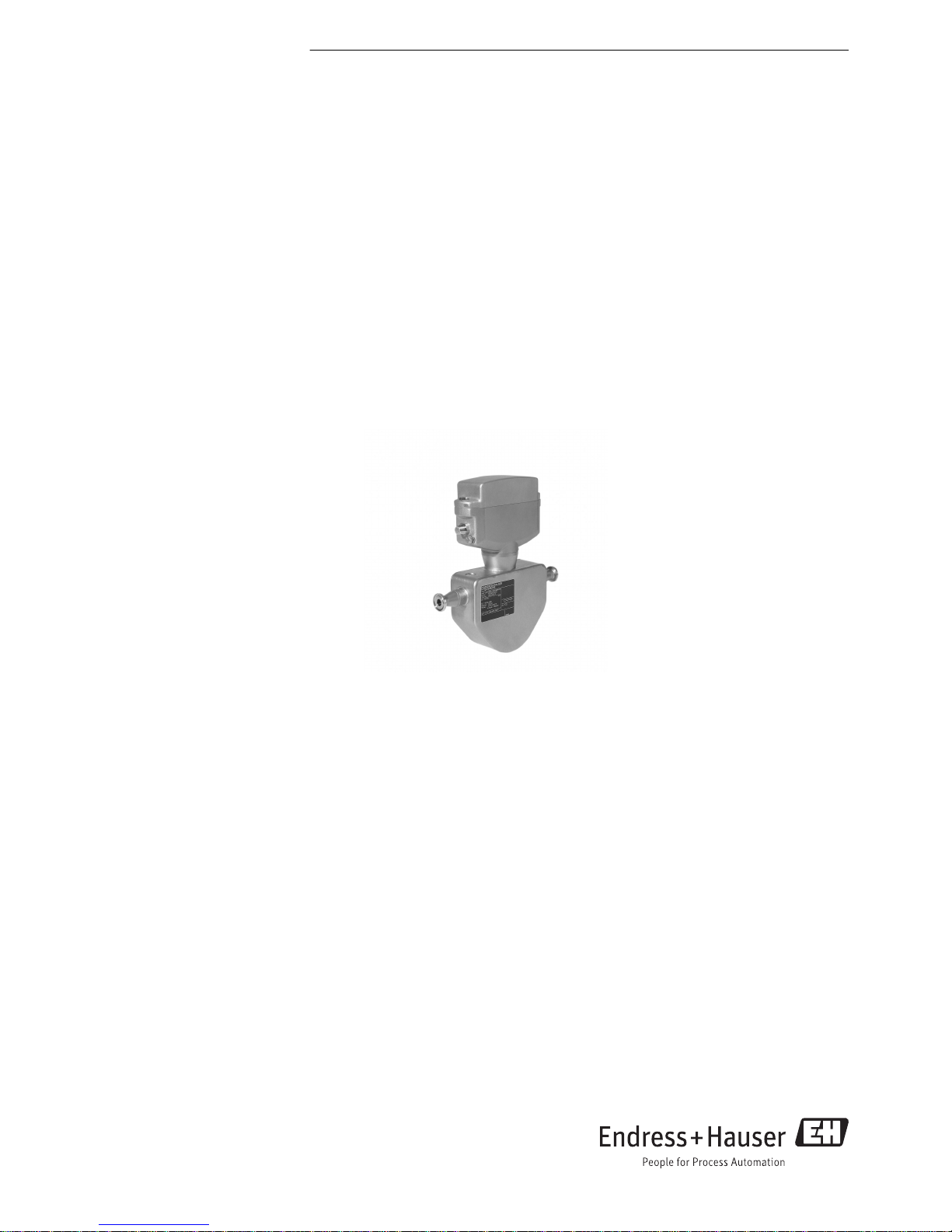
The compact sensor with an ultra-compact transmitter
Application
• Measuring principle operates independently of physical fluid
properties such as viscosity or density
• Measurement of liquids in continuous process control and in
batching applications
Device properties
• Nominal diameter: DN 8 to 25 (³⁄₈ to 1")
• Many hygienic process connections, 3A‐compliant
• Sensor can be cleaned/sterilized in place (CIP/SIP)
• Robust, ultra-compact transmitter housing
• Pulse/frequency/switch output, Modbus RS485
• Excellent and easy-to-clean transmitter
Your benefits
• High process safety – high measuring accuracy for different
media in shortest filling time
• Fewer process measuring points – multivariable
measurement (flow, density, temperature)
• Space‐saving installation – no in/outlet run needs
• Versatile and time‐saving wiring – plug connector
• Fast commissioning – pre-configured devices
• Automatic recovery of data for servicing
Products Solutions Services
Technical Information
Dosimass
Coriolis flowmeter
TI00065D/06/EN/16.15
71291606
Page 2

Dosimass
2 Endress+Hauser
Table of contents
Document information ....................... 3
Symbols used ................................ 3
Function and system design ................... 4
Measuring principle ............................ 4
Measuring system ............................. 4
Equipment architecture ......................... 5
Safety ..................................... 6
Input ..................................... 7
Measured variable ............................. 7
Measuring range .............................. 7
Operable flow range ........................... 7
Input signal ................................. 7
Output ................................... 8
Output signal ................................ 8
Signal on alarm ............................... 9
Low flow cut off .............................. 9
Galvanic isolation ............................. 9
Protocol-specific data .......................... 10
Power supply ............................. 10
Terminal assignment .......................... 10
Pin assignment, device plug ...................... 11
Supply voltage .............................. 14
Power consumption ........................... 14
Current consumption .......................... 14
Power supply failure .......................... 14
Electrical connection .......................... 14
Potential equalization ......................... 15
Cable specification ............................ 15
Performance characteristics .................. 15
Reference operating conditions ................... 15
Maximum measured error ....................... 15
Repeatability ............................... 17
Response time .............................. 17
Influence of ambient temperature ................. 17
Influence of medium temperature .................. 17
Influence of medium pressure .................... 17
Installation ............................... 17
Mounting location ............................ 17
Orientation ................................ 18
Inlet and outlet runs .......................... 20
Special mounting instructions .................... 20
Environment .............................. 21
Ambient temperature range ..................... 21
Storage temperature .......................... 22
Degree of protection .......................... 22
Shock resistance ............................. 22
Vibration resistance ........................... 22
Interior cleaning ............................. 22
Electromagnetic compatibility (EMC) ............... 22
Process .................................. 22
Medium temperature range ...................... 22
Medium pressure range (nominal pressure) ........... 22
Density ................................... 22
Pressure-temperature ratings .................... 22
Secondary containment pressure rating .............. 24
Flow limit ................................. 24
Pressure loss ............................... 24
Heating ................................... 24
Vibrations ................................. 24
Mechanical construction .................... 25
Dimensions in SI units ......................... 25
Dimensions in US units ......................... 29
Weight ................................... 32
Materials .................................. 32
Process connections ........................... 32
Operability ............................... 33
Local operation .............................. 33
Remote operation ............................ 33
Certificates and approvals ................... 33
CE mark ................................... 33
C-Tick symbol ............................... 34
Ex approval ................................ 34
Hygienic compatibility ......................... 34
Pressure Equipment Directive .................... 34
Other standards and guidelines ................... 34
Ordering information ....................... 35
Accessories ............................... 35
Communication-specific accessories ................ 35
Service-specific accessories ...................... 35
Supplementary documentation ............... 36
Standard documentation ........................ 36
Supplementary device-dependent documentation ....... 37
Registered trademarks ...................... 37
Page 3
Dosimass
Endress+Hauser 3
Document information
Symbols used Electrical symbols
Symbol Meaning Symbol Meaning
Direct current Alternating current
Direct current and alternating current Ground connection
A grounded terminal which, as far as
the operator is concerned, is
grounded via a grounding system.
Protective ground connection
A terminal which must be connected
to ground prior to establishing any
other connections.
Equipotential connection
A connection that has to be connected
to the plant grounding system: This
may be a potential equalization line
or a star grounding system depending
on national or company codes of
practice.
Symbols for certain types of information
Symbol Meaning
Permitted
Procedures, processes or actions that are permitted.
Preferred
Procedures, processes or actions that are preferred.
Forbidden
Procedures, processes or actions that are forbidden.
Tip
Indicates additional information.
Reference to documentation
Reference to page
Reference to graphic
Visual inspection
Symbols in graphics
Symbol Meaning Symbol Meaning
1, 2, 3,... Item numbers
,…,
Series of steps
A, B, C, ... Views A-A, B-B, C-C, ... Sections
-
Hazardous area
.
Safe area (non-hazardous area)
Flow direction
Page 4
Dosimass
4 Endress+Hauser
Function and system design
Measuring principle
The measuring principle is based on the controlled generation of Coriolis forces. These forces are
always present in a system when both translational and rotational movements are superimposed.
Fc = 2 · ∆m (ν · ω)
Fc = Coriolis force
∆m = moving mass
ω = rotational velocity
ν = radial velocity in rotating or oscillating system
The amplitude of the Coriolis force depends on the moving mass ∆m, its velocity ν in the system and
thus on the mass flow. Instead of a constant rotational velocity ω, the sensor uses oscillation.
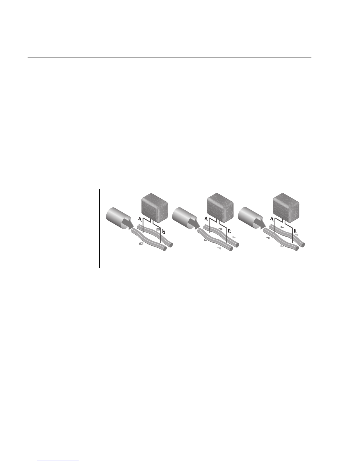
In the sensor, two parallel measuring tubes containing flowing fluid oscillate in antiphase, acting like
a tuning fork. The Coriolis forces produced at the measuring tubes cause a phase shift in the tube
oscillations (see illustration):
• At zero flow (when the fluid is at a standstill) the two tubes oscillate in phase (1).
• Mass flow causes deceleration of the oscillation at the inlet of the tubes (2) and acceleration at the
outlet (3).
1 2 3
A0016771
The phase difference (A-B) increases with increasing mass flow. Electrodynamic sensors register the
tube oscillations at the inlet and outlet. System balance is ensured by the antiphase oscillation of the
two measuring tubes. The measuring principle operates independently of temperature, pressure,
viscosity, conductivity and flow profile.
Density measurement
The measuring tube is continuously excited at its resonance frequency. A change in the mass and
thus the density of the oscillating system (comprising measuring tube and fluid) results in a
corresponding, automatic adjustment in the oscillation frequency. Resonance frequency is thus a
function of medium density. The microprocessor utilizes this relationship to obtain a density signal.
Temperature measurement
The temperature of the measuring tube is determined in order to calculate the compensation factor
due to temperature effects. This signal corresponds to the process temperature and is also available
as an output signal.
Measuring system
The device consists of a transmitter and a sensor.
The device is available as a compact version:
The transmitter and sensor form a mechanical unit.
Page 5
Dosimass
Endress+Hauser 5
Dosimass
A0023382
Transmitter
• Materials:
– Transmitter housing: stainless steel 1.4308 (304)
– Housing seal: EPDM
• Configuration:
Via operating tools (e.g. FieldCare)
Sensor
• Range of nominal diameter: DN 8 (³⁄₈"), 15 (½"), 25 (1")
• Materials:
– Sensor housing: stainless steel 1.4301 (304)
– Measuring tube: stainless steel 1.4539 (904L)
– Process connections: stainless steel 1.4404 (316/316L) and 1.4435
(316L)
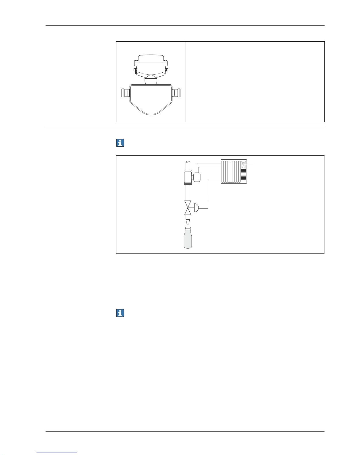
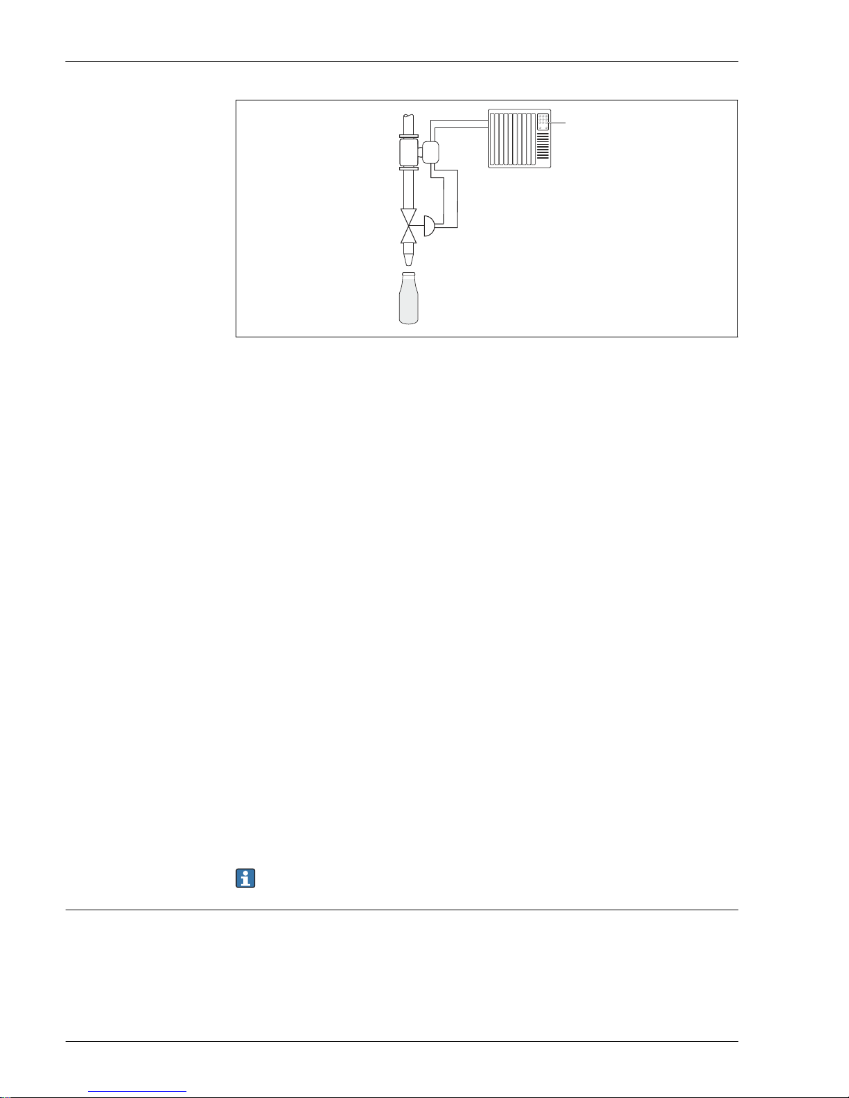
Equipment architecture Device version: Two pulse/frequency/switch outputs
The device version has two pulse/frequency/switch outputs → 10.
4
1
2
3
A0027057
1 Options for integration into a system for batching processes
1 Pulse/frequency/current output 1
2 Pulse/frequency/current output 2
3 Automation system (e.g. PLC)
4 Control of valve (by automation system)
Device version: Modbus RS485, one or two switch outputs (Batch) and one status input
Device versions with MODBUS RS485 have one or two switch outputs for valve control for the
regulation of batching processes→ 10.
Page 6
Dosimass
6 Endress+Hauser
4 5
1
2
3
A0026621
2 Options for integration into a system for batching processes
1 MODBUS RS485: Measured value (to the automation system)
2 Status input: Control of batching process (by the automation system)
3 Automation system (e.g. PLC)
4 Switch output 1 (batch): valve control, level 1
5 Switch output 2 (batch): valve control, level 2
Integrated batching functions
The following parameters can be used to configure and monitor batching processes.
Configuration
• Measured variable: mass or volume flow
• Unit
• Batch quantity
• Fixed compensation quantity
• Select batch profile
• Drip correction mode: Off, low flow cut off or fixed time
• Measuring time drip quantity
• Filter depth drip median (3, 5 or 7)
• Average drip correction quantity
• Batch levels: One-level, two-level or one-level and blow out
• Start and stop level 2
• Blow out delay and duration
• Maximum batch time
• Maximum flow
• Disable time pressure shock suppression
Display
• Total amount measured from last batching process (incl. drip quantity)
• Duration of last batching process (incl. measurement of drip quantity)
• Switch-off time: From time of switch-off to when measurement of the drip quantity is complete
• Current drip correction quantity (drip correction quantity for next batching process)
• Sum of all batching processes measured
• Number of batching processes.
The batching process (start batch, stop batch etc.) is controlled by the automation system via
the status input or the Modbus RS485 .
Safety IT security
We only provide a warranty if the device is installed and used as described in the Operating
Instructions. The device is equipped with security mechanisms to protect it against any inadvertent
changes to the device settings.
IT security measures in line with operators' security standards and designed to provide additional
protection for the device and device data transfer must be implemented by the operators themselves.
Page 7
Dosimass
Endress+Hauser 7
Input
Measured variable Direct measured variables
• Mass flow
• Density
• Temperature
Calculated measured variables
Volume flow
Measuring range
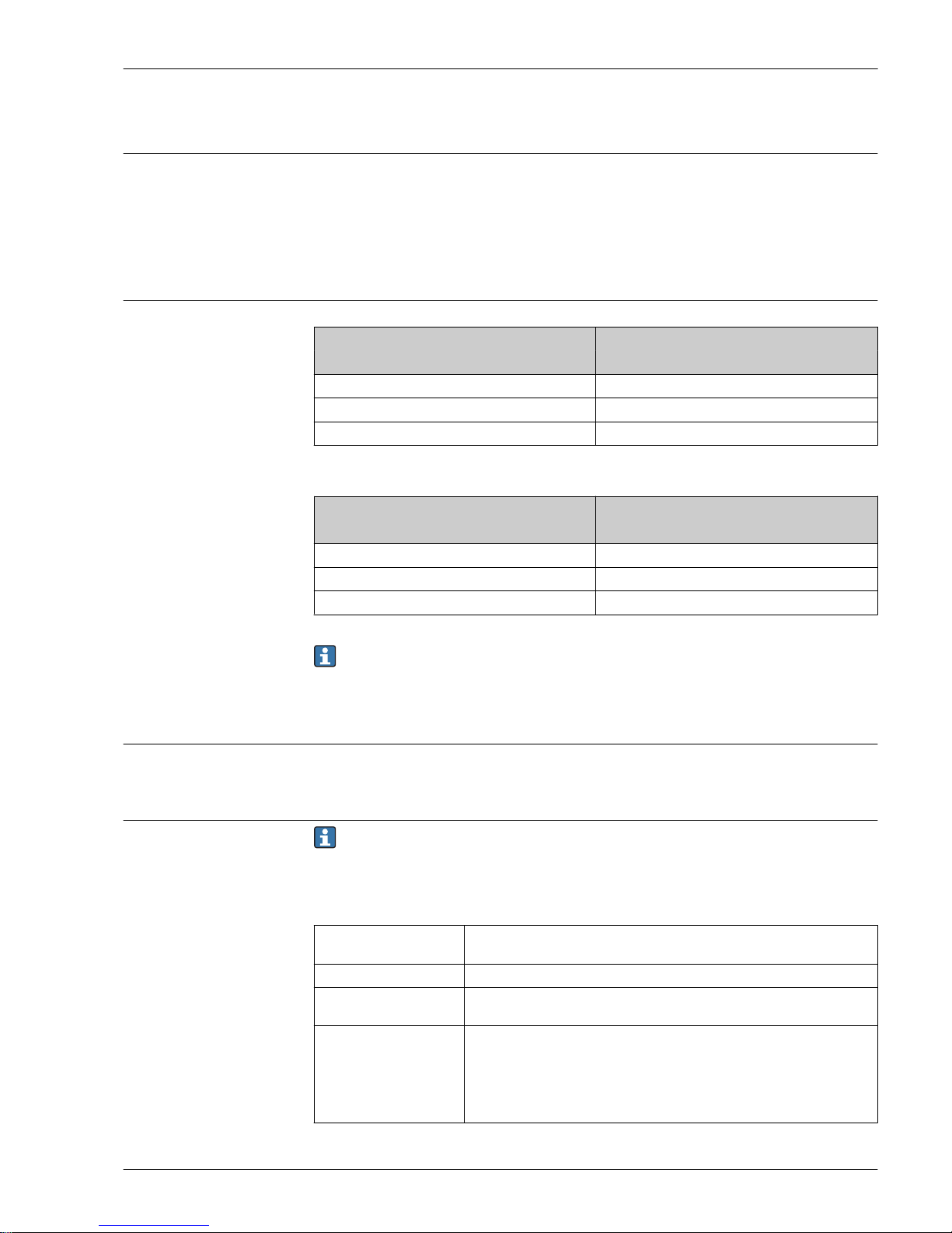
Flow values in SI units
DN Measuring range full scale values
min(F)
to
max(F)
[mm] [kg/h]
8 0 to 2 000
15 0 to 6 500
25 0 to 18 000
Flow values in US units
DN Measuring range full scale values
min(F)
to
max(F)
[in] [lb/min]
³⁄₈ 0 to 73.50
½ 0 to 238.9
1 0 to 661.5
To calculate the measuring range, use the Applicator product selection tool → 35
Recommended measuring range
"Flow limit" section → 24
Operable flow range
Over 1000 : 1.
Flow rates above the preset full scale value are not overridden by the electronics unit, with the result
that the totalizer values are registered correctly.
Input signal
Available only for device versions using the Modbus RS485 communication method → 10.
Status input
The batching process is controlled by the automation system via the device's status input.
Maximum input values • DC 30 V
• 6 mA
Response time Adjustable: 10 to 200 ms
Input signal level • Low level: 0 to 1.5 V
• High level: 3 to 30 V
Assignable functions • Off
• Start batching process
• Start and stop batching process
• Reset totalizers 1-3 separately
• Reset all totalizers
• Flow override
Page 8
Dosimass
8 Endress+Hauser
Output
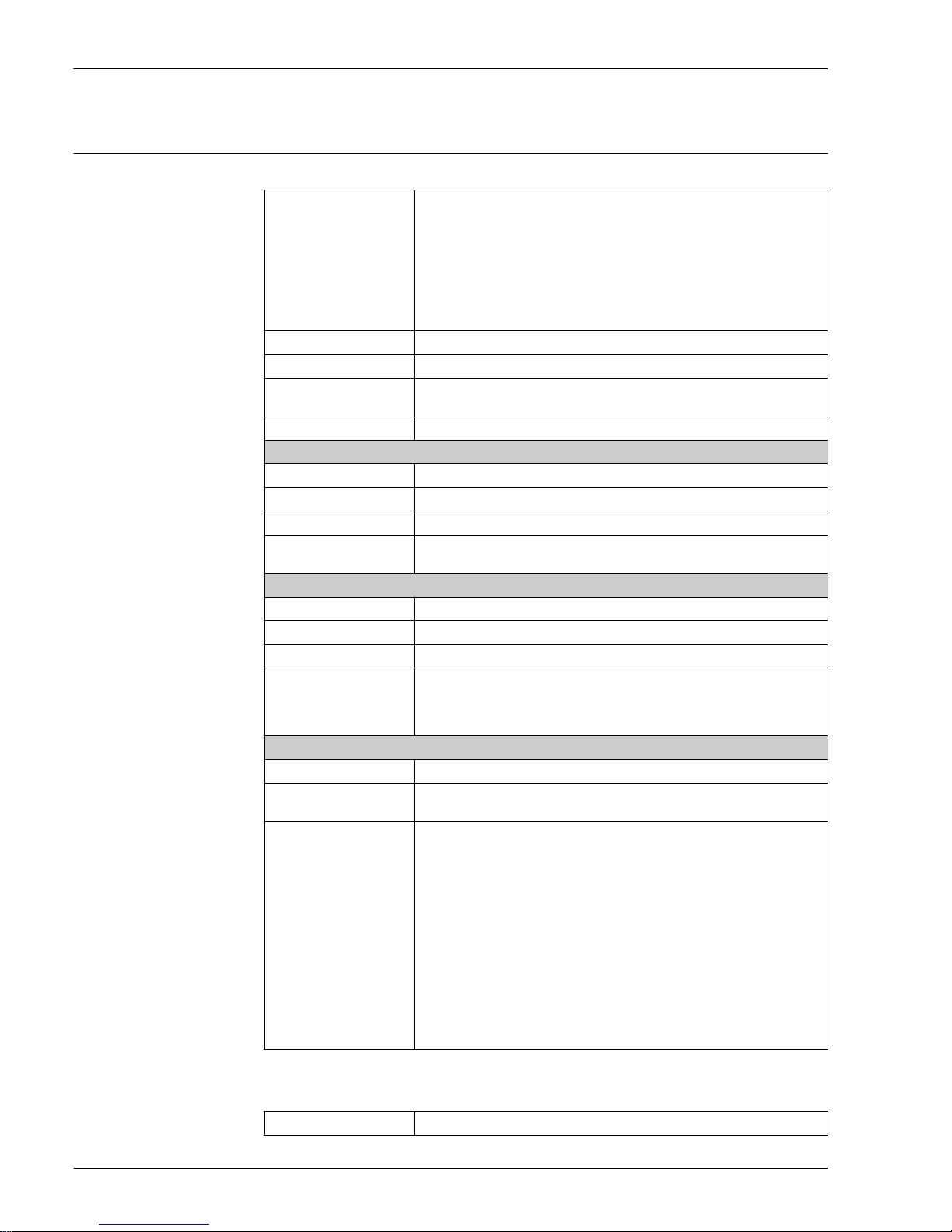
Output signal Pulse/frequency/switch output
Function Can be set to:
• Pulse
Quantity-proportional pulse with pulse width to be configured.
• Automatic pulse
Quantity-proportional pulse with on/off ratio of 1:1
• Frequency
Flow-proportional frequency output with on/off ratio of 1:1
• Switch
Contact for displaying a status
Channel 2 Redundant output of pulse output: 0°, 90° or 180°
Version Passive, open emitter
Maximum input values • DC 30 V
• 25 mA
Voltage drop At 25 mA: ≤ DC 2 V
Pulse output
Pulse width Adjustable: 0.05 to 3.75 ms
Maximum pulse rate 10 000 Impulse/s
Pulse value Adjustable
Assignable measured
variables
• Mass flow
• Volume flow
Frequency output
Output frequency Adjustable: 0 to 10 000 Hz
Damping Adjustable: 0 to 999.9 s
Pulse/pause ratio 1:1
Assignable measured
variables
• Mass flow
• Volume flow
• Density
• Temperature
Switch output
Switching behavior Binary, conductive or non-conductive
Number of switching
cycles
Unlimited
Assignable functions • Off
• On
• Diagnostic behavior
– Alarm
– Alarm and warning
– Warning
• Limit value
– Mass flow
– Volume flow
– Density
– Temperature
• Flow direction monitoring
• Status
– Partially filled pipe detection
– Low flow cut off
Modbus RS485
Physical interface In accordance with EIA/TIA-485-A standard
Page 9
Dosimass
Endress+Hauser 9
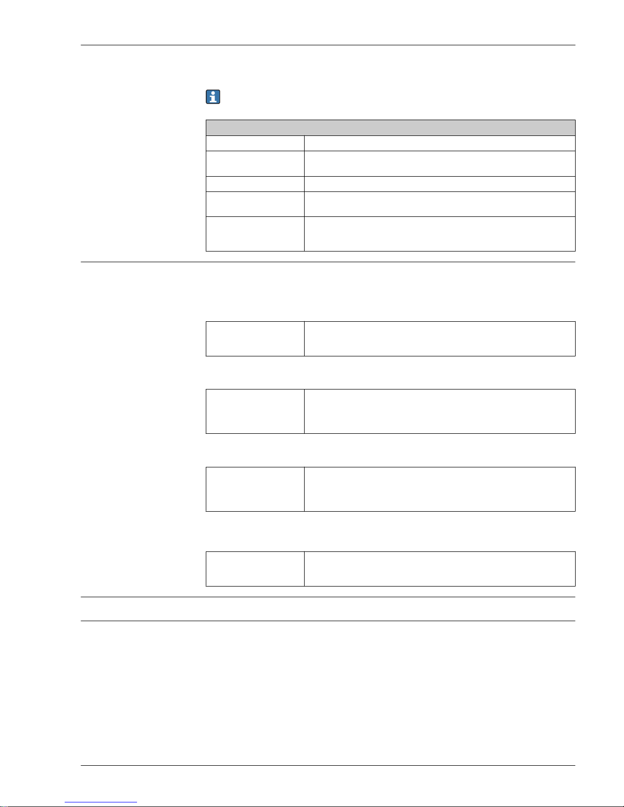
Switch output (batch: valve control)
• Only available for device version with Modbus RS485 → 10.
• Depending on the device version, the device has one or two switch outputs.
Switch output
Version Active, open emitter
Maximum input values • DC 30 V
• 500 mA
Switching behavior Binary, conductive or non-conductive
Number of switching
cycles
Unlimited
Assignable functions • Open
• Closed
• Batching
Signal on alarm
Depending on the interface, failure information is displayed as follows:
Pulse/frequency/switch output
Pulse output
Failure mode Choose from:
• Actual value
• No pulses
Frequency output
Failure mode Choose from:
• Actual value
• 0 Hz
• Defined value: 0 to 10 000 Hz
Switch output
Failure mode Choose from:
• Current status
• Open
• Closed
Modbus RS485
Failure mode Choose from:
• NaN value instead of current value
• Last valid value
Low flow cut off
The switch points for low flow cut off are user-selectable.
Galvanic isolation
• Device version: 2 pulse/frequency/switch outputs
Order code for "Output, input", option 3:
– Pulse/frequency/switch outputs galvanically isolated from supply potential.
– Pulse/frequency/switch outputs not galvanically isolated from each other.
• Device version: Modbus RS485, 1 switch output (batch), 1 status input
(Order code for "Output, input": option 4)
Switch outputs (batch) and status input on supply potential
• Device version: Modbus RS485, 2 switch outputs (batch), 1 status input
(Order code for "Output, input", option 5:)
– Switch outputs (batch) on supply potential.
– Status input, galvanically isolated.
Page 10
Dosimass
10 Endress+Hauser
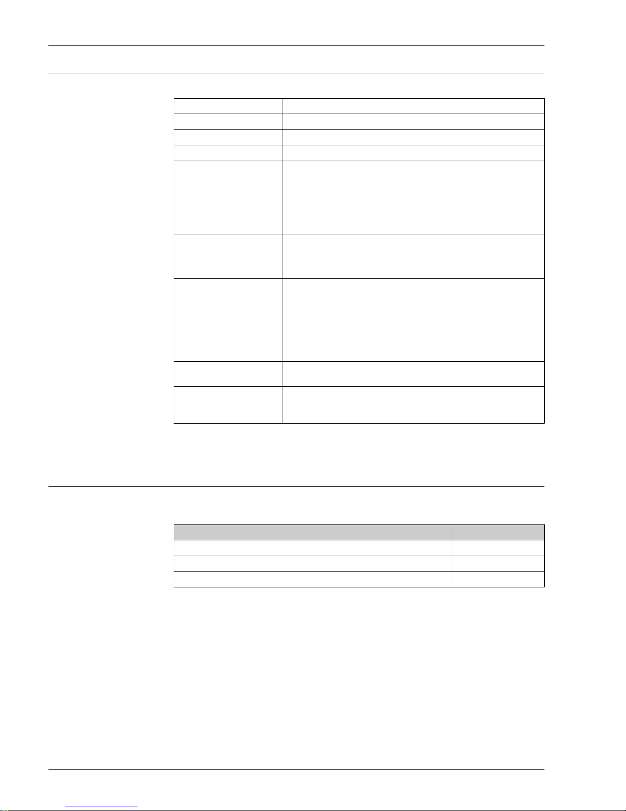
Protocol-specific data Modbus RS485
Protocol Modbus Applications Protocol Specification V1.1
Device type Slave
Slave address range 1 to 247
Broadcast address range 0
Function codes • 03: Read holding register
• 04: Read input register
• 06: Write single registers
• 08: Diagnostics
• 16: Write multiple registers
• 23: Read/write multiple registers
• 43: Read device identification
Broadcast messages Supported by the following function codes:
• 06: Write single registers
• 16: Write multiple registers
• 23: Read/write multiple registers
Supported baud rate • 1 200 BAUD
• 2 400 BAUD
• 4 800 BAUD
• 9 600 BAUD
• 19 200 BAUD
• 38 400 BAUD
• 57 600 BAUD
• 115 200 BAUD
Data transfer mode • ASCII
• RTU
Data access Each device parameter can be accessed via Modbus RS485.
For Modbus register information → 36
Power supply
Terminal assignment
Connection is solely by means of device plug:
There are different device versions available:
Order code for "Output, input": Device plug
Option 3: 2 pulse/frequency/switch outputs → 11
Option 4: Modbus RS485, 1 switch output (batch), 1 status input → 12
Option 5: Modbus RS485, 2 switch outputs (batch), 1 status input → 13
Page 11
Dosimass
Endress+Hauser 11
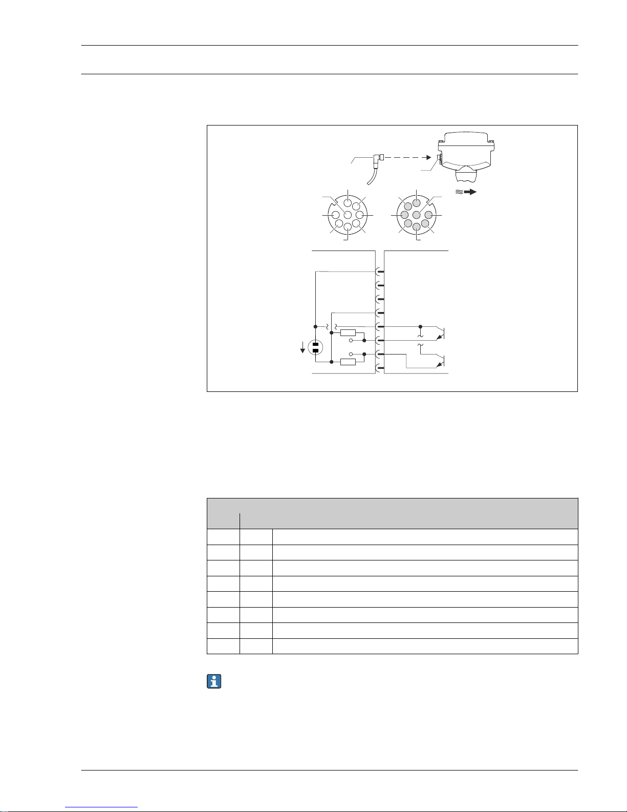
Pin assignment, device plug Device version: 2 pulse/frequency/switch outputs
Order code for "Output, input", option 3:
2 Pulse/frequency/switch output
BA
8
A B
RSE 8
M12x1
1
2
4
6
8
3
5 7
1
2
4
6
8
3
57
1
2
3
4
5
6
7
+
-
E
A0023237
3 Connection to device
A Coupling: Supply voltage, pulse/freq./switch output
B Connector: Supply voltage, pulse/freq./switch output
E PELV or SELV power supply
1 to8Pin assignment
Pin assignment
Connection: Coupling (A) – Connector (B)
Pin Assignment
1 L+ Supply voltage
2 + Service interface RX
3 + Service interface TX
4 L- Supply voltage
5 + Pulse/frequency/switch output
6 – Pulse/frequency/switch output 1
7 – Pulse/frequency/switch output 2
8 – Service interface GND
Observe cable specifications → 15.
Page 12
Dosimass
12 Endress+Hauser
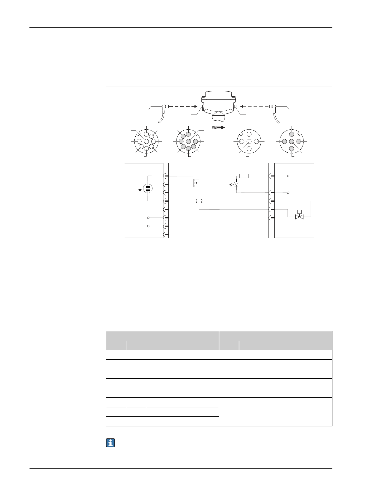
Device version: Modbus RS485, status output and status input
Order code for "Output, input", option 4:
• Modbus RS485
• 1 switch output (batch)
• 1 status input
C
BA D
C
8
A DB
RSE 5
M12x1
RSE 8
M12x1
3
2
4
1
5
1
2
4
3
5
1
2
4
6
8
3
5 7
1
2
4
6
8
3
57
1
2
3
4
5
6
7
2
3
1
5
+
-
E
4
V1
A0023238
4 Connection to device
A Coupling: Supply voltage, Modbus RS485
B Connector: Supply voltage, Modbus RS485
C Coupling: Switch output (batch), status input
D Connector: Switch output (batch), status input
E PELV or SELV power supply
V1 Valve 1 (batch)
1 to8Pin assignment
Pin assignment
Connection: Coupling (A) – Connector (B) Connection: Coupling (C) – Connector (D)
Pin Assignment Pin Assignment
1 L+ Supply voltage 1 + Status input
2 + Service interface RX 2 – Status input
3 + Service interface TX 3 – Switch output (batch)
4 L- Supply voltage 4 + Switch output (batch)
5 Not assigned 5 Not assigned
6 A Modbus RS485
7 B Modbus RS485
8 – Service interface GND
Observe cable specifications → 15.
Page 13
Dosimass
Endress+Hauser 13
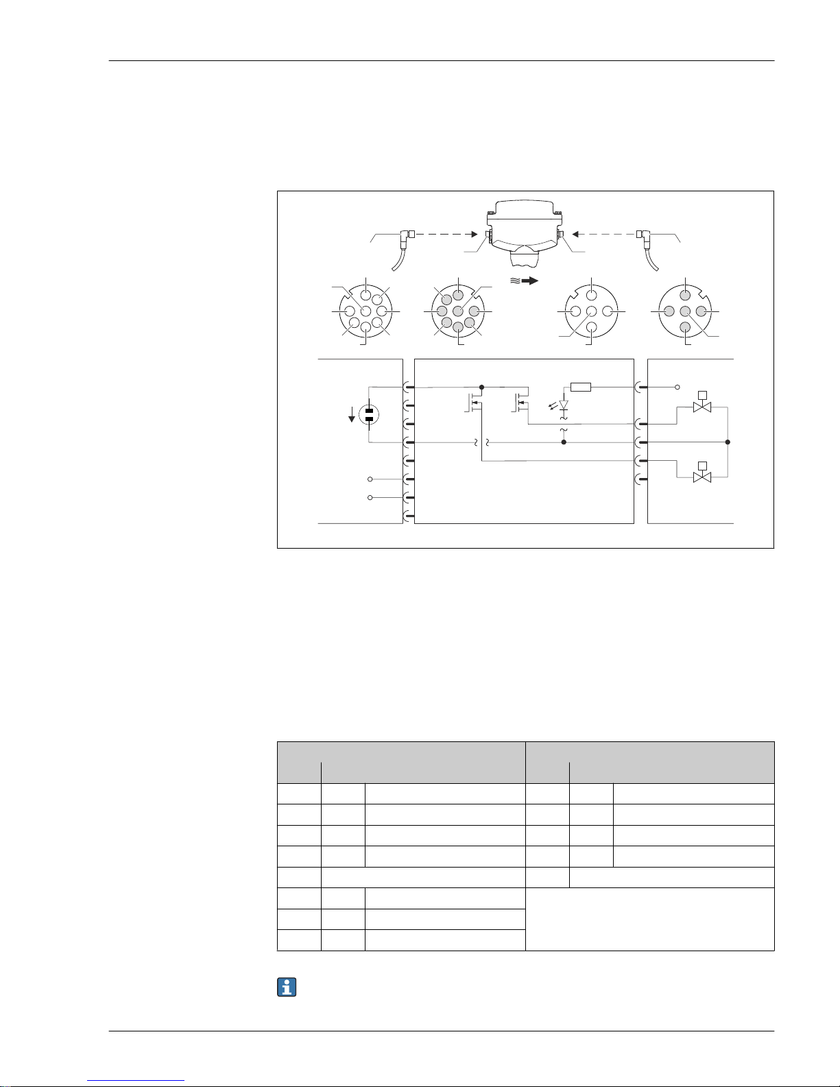
Device version: Modbus RS485 , 2 status outputs and status input
Order code for "Output, input", option 5:
• Modbus RS485
• 2 switch outputs (batch)
• 1 status input
C
BA D
C
1
2
3
4
5
6
7
8
2
3
1
5
A
+
-
E
4
D
V2
V1
B
RSE 5
M12x1
RSE 8
M12x1
3
2
4
1
5
1
2
4
3
5
1
2
4
6
8
3
5 7
1
2
4
6
8
3
57
A0023239
5 Connection to device
A Coupling: Supply voltage, Modbus RS485
B Connector: Supply voltage, Modbus RS485
C Coupling: Switch outputs (batch), status input
D Connector: Switch outputs (batch), status input
E PELV or SELV power supply
V1 Valve (batch), level 1
V2 Valve (batch), level 2
1 to8Pin assignment
Pin assignment
Connection: Coupling (A) – Connector (B) Connection: Coupling (C) – Connector (D)
Pin Assignment Pin Assignment
1 L+ Supply voltage 1 + Status input
2 + Service interface RX 2 + Switch output (batch) 2
3 + Service interface TX 3 – Switch outputs, status input
4 L- Supply voltage 4 + Switch output (batch) 1
5 Not assigned 5 Not assigned
6 A Modbus RS485
7 B Modbus RS485
8 – Service interface GND
Observe cable specifications → 15.
Page 14
Dosimass
14 Endress+Hauser
Supply voltage
DC 24 V (nominal voltage: DC 20 to 30 V)
• The power unit must be tested to ensure that it meets safety requirements (e.g. PELV, SELV).
• The supply voltage must not exceed a maximum short-circuit current of 50 A.
Power consumption
3.5 W
Current consumption
Order code for "Output, input":
Maximum
Current consumption
Option 3: 2 pulse/frequency/switch outputs 175 mA
Option 4: Modbus RS485, 1 switch output (batch), 1 status input 175 mA + 500 mA
1)
Option 5: Modbus RS485, 2 switch outputs (batch), 1 status input 175 mA + 1 000 mA
1)
1) Additional 500 mA per switch output (batch) used.
Switch-on current: max. 1 A (< 6 ms)
Power supply failure
• Totalizers stop at the last value measured.
• Error messages (incl. total operated hours) are stored.
Electrical connection
Connection is solely by means of device plug:
B
A
D
C
A0023691
A, C Coupling
B, D Plug
There are different device versions available:
Order code for "Output, input": Device plug
Option 3: 2 pulse/frequency/switch outputs → 11
Option 4: Modbus RS485, 1 switch output (batch), 1 status input → 12
Option 5: Modbus RS485, 2 switch outputs (batch), 1 status input → 13
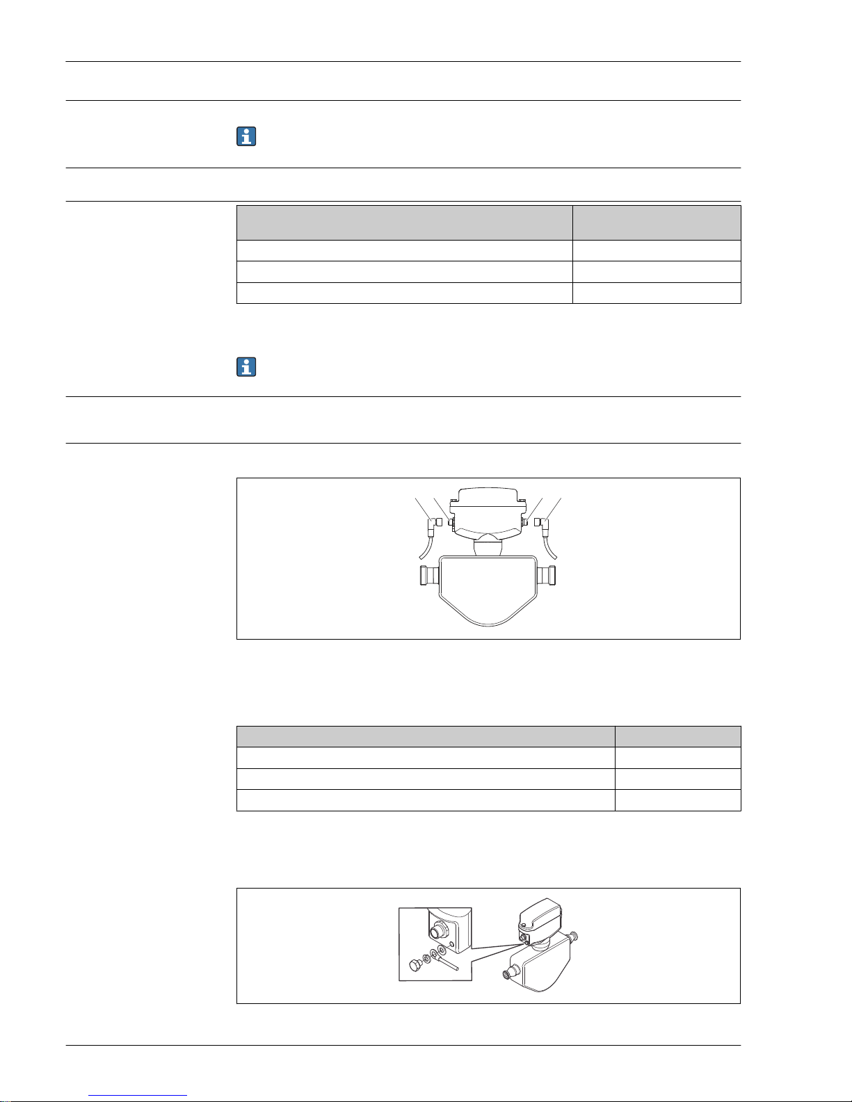
Grounding
Grounding is by means of a cable socket.
A0007235
Page 15
Dosimass
Endress+Hauser 15
Potential equalization Requirements
No special measures for potential equalization are required.
For devices intended for use in hazardous locations, please observe the guidelines in the Ex
documentation (XA).
Cable specification Permitted temperature range
• –40 °C (–40 °F) to +80 °C (+176 °F)
• Minimum requirement: cable temperature range ≥ ambient temperature +20 K
Signal cable
Cables are not included in the scope of delivery; they can be ordered as an accessory → 35.
Pulse/frequency/switch output
Standard installation cable is sufficient.
Status input and switch output (batch)
Standard installation cable is sufficient.
Modbus RS485
• The electrical connection of the shield to the device housing must be properly implemented
(e.g. using a knurled nut).
• Please note the following with regard to cable loading:
– Voltage drop due to the cable length and cable type.
– Valve performance.
Total length of cable in the Modbus network ≤ 50 m
Use a shielded cable.
Example:
Terminated device connector with cable: Lumberg RKWTH 8-299/10
Total length of cable in the Modbus network > 50 m
Use shielded twisted pair cable for RS485 applications.
Example:
• Cable: Belden item no. 9842 (for 4-wire version, the same cable can be used for the power supply)
• Terminated device plug: Lumberg RKCS 8/9 (shieldable version)
Performance characteristics
Reference operating
conditions
Error limits based on ISO 11631
• Water at +15 to +45 °C (+59 to +113 °F) at2 to 6 bar (29 to 87 psi)
• Specifications as per calibration protocol
• Accuracy based on accredited calibration rigs that are traced to ISO 17025.
To obtain measured errors, use the Applicator sizing tool → 35
Maximum measured error
o.r. = of reading; 1 g/cm³ = 1 kg/l; T = medium temperature
Base accuracy
Mass flow and volume flow (liquids)
• ±0.15 % o.r.
• ±0.30 % ± [(zero point stability : measured value) · 100] % o.r.
• ±5 % ± [(zero point stability : measured value) · 100] % o.r.
Page 16
Dosimass
16 Endress+Hauser
Density (liquids)
• Reference operating conditions: ±0.0005 g/cm³
• Field density calibration: ±0.0005 g/cm³
(after field density calibration under process conditions)
• Standard density calibration: ±0.02 g/cm³
(valid over the entire temperature range and density range )
Temperature
±0.5 °C ± 0.005 · T °C (±0.9 °F ± 0.003 · (T – 32) °F)
Zero point stability
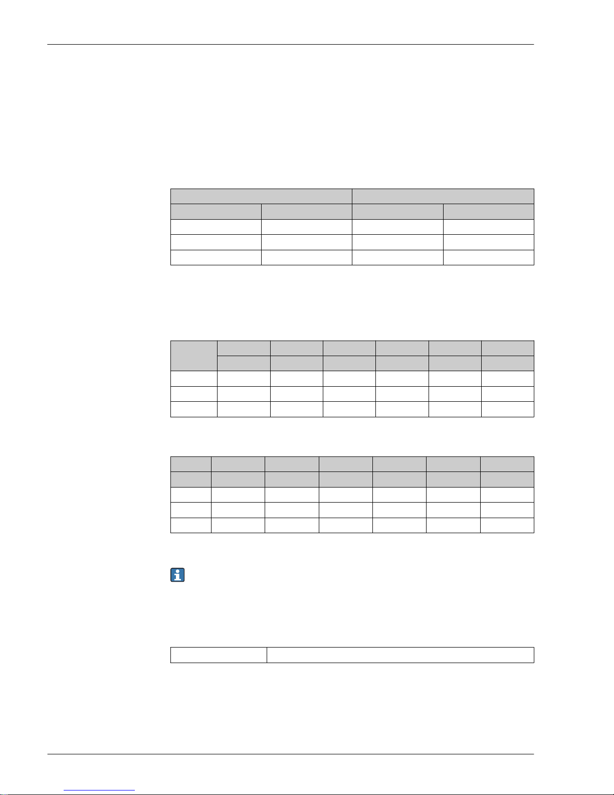
DN Zero point stability
[mm] [in] [kg/h] [lb/min]
8 ³⁄₈ 0.20 0.007
15 ½ 0.65 0.024
25 1 1.80 0.066
Flow values
Flow values as turndown parameter depending on nominal diameter.
SI units
DN 1:1 1:10 1:20 1:50 1:100 1:500
[mm]
[kg/h] [kg/h] [kg/h] [kg/h] [kg/h] [kg/h]
8 2 000 200 100 40 20 4
15 6 500 650 325 130 65 13
25 18 000 1 800 900 360 180 36
US units
DN 1:1 1:10 1:20 1:50 1:100 1:500
[inch] [lb/min] [lb/min] [lb/min] [lb/min] [lb/min] [lb/min]
³⁄₈ 73.50 7.350 3.675 1.470 0.735 0.147
½ 238.9 23.89 11.95 4.778 2.389 0.478
1 661.5 66.15 33.08 13.23 6.615 1.323
Accuracy of outputs
In the case of analog outputs, the output accuracy must also be considered for the measured
error, in contrast, this need not be considered in the case of fieldbus outputs (Modbus RS485).
The outputs have the following base accuracy specifications.
Pulse/frequency output
o.r. = of reading
Accuracy Max. ±50 ppm o.r. (across the entire ambient temperature range)
Page 17
Dosimass
Endress+Hauser 17
Repeatability Base repeatability
Dosing time [s] Standard deviation [%]
≥ 0.75 0.2
≥ 1.5 0.1
≥ 3.0 0.05
Density (liquids)
±0.00025 g/cm
3
Temperature
±0.25 °C ± 0.0025 · T °C (±0.45 °F ± 0.0015 · (T–32) °F)
Response time
The response time depends on the configuration (damping).
Influence of ambient
temperature
Pulse/frequency output
Temperature coefficient No additional effect. Included in accuracy.
Influence of medium
temperature
Mass flow
If there is a differential between the temperature during zero point adjustment and the process
temperature, the typical measured error of the sensor is ±0.0003 % of the full scale value/°C
(±0.00015 % of the full scale value/°F).
Temperature
±0.005 · T °C (± 0.005 · (T – 32) °F)
Influence of medium
pressure
A difference between the calibration pressure and process pressure does not affect accuracy.
Installation
No special measures such as supports are necessary. External forces are absorbed by the construction
of the device.
Mounting location
A0023344
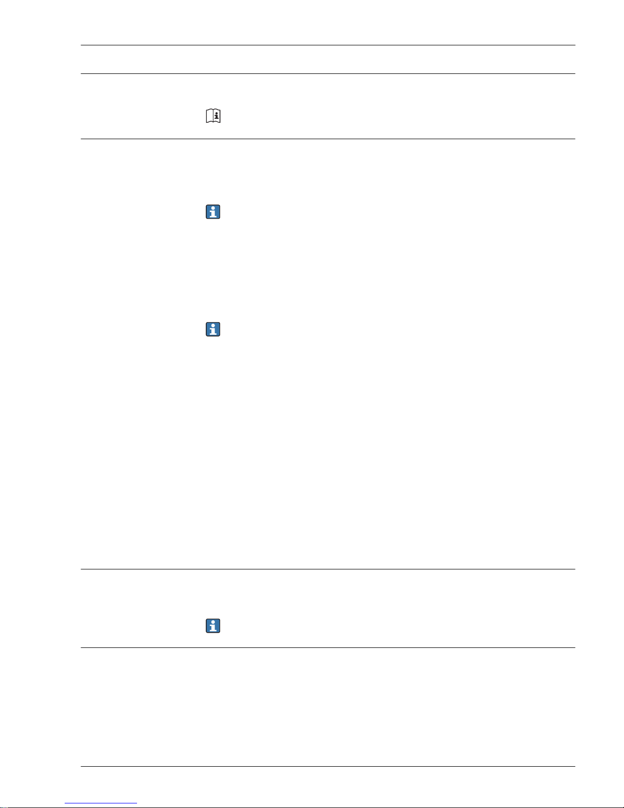
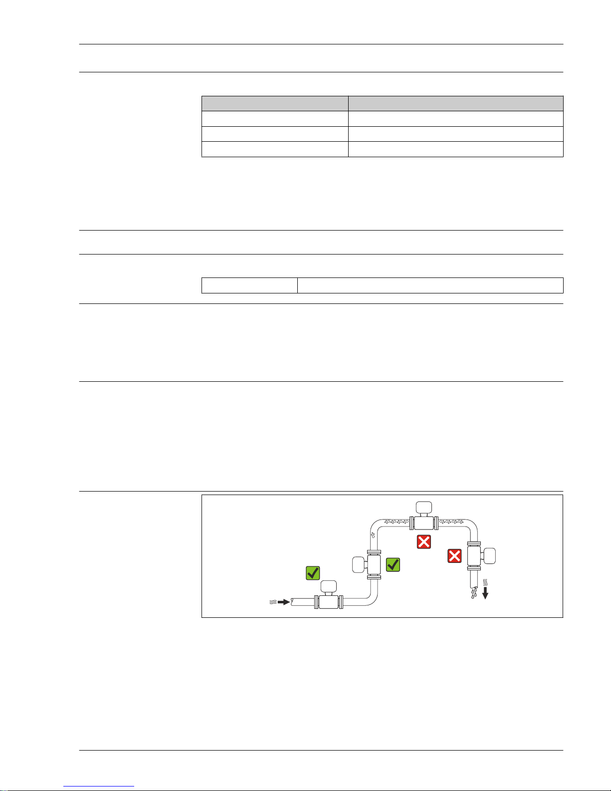
To prevent measuring errors arising from accumulation of gas bubbles in the measuring tube, avoid
the following mounting locations in the pipe:
• Highest point of a pipeline.
• Directly upstream of a free pipe outlet in a down pipe.
Installation in down pipes
However, the following installation suggestion allows for installation in an open vertical pipeline.
Pipe restrictions or the use of an orifice with a smaller cross-section than the nominal diameter
prevent the sensor running empty while measurement is in progress.
Page 18
Dosimass
18 Endress+Hauser
1
2
3
4
5
A0015596
6 Installation in a down pipe (e.g. for batching applications)
1 Supply tank
2 Sensor
3 Orifice plate, pipe restriction
4 Valve
5 Batching tank
DN Ø orifice plate, pipe restriction
[mm] [in] [mm] [in]
8 ³⁄₈ 6 0.24
15 ½ 10 0.40
25 1 14 0.55
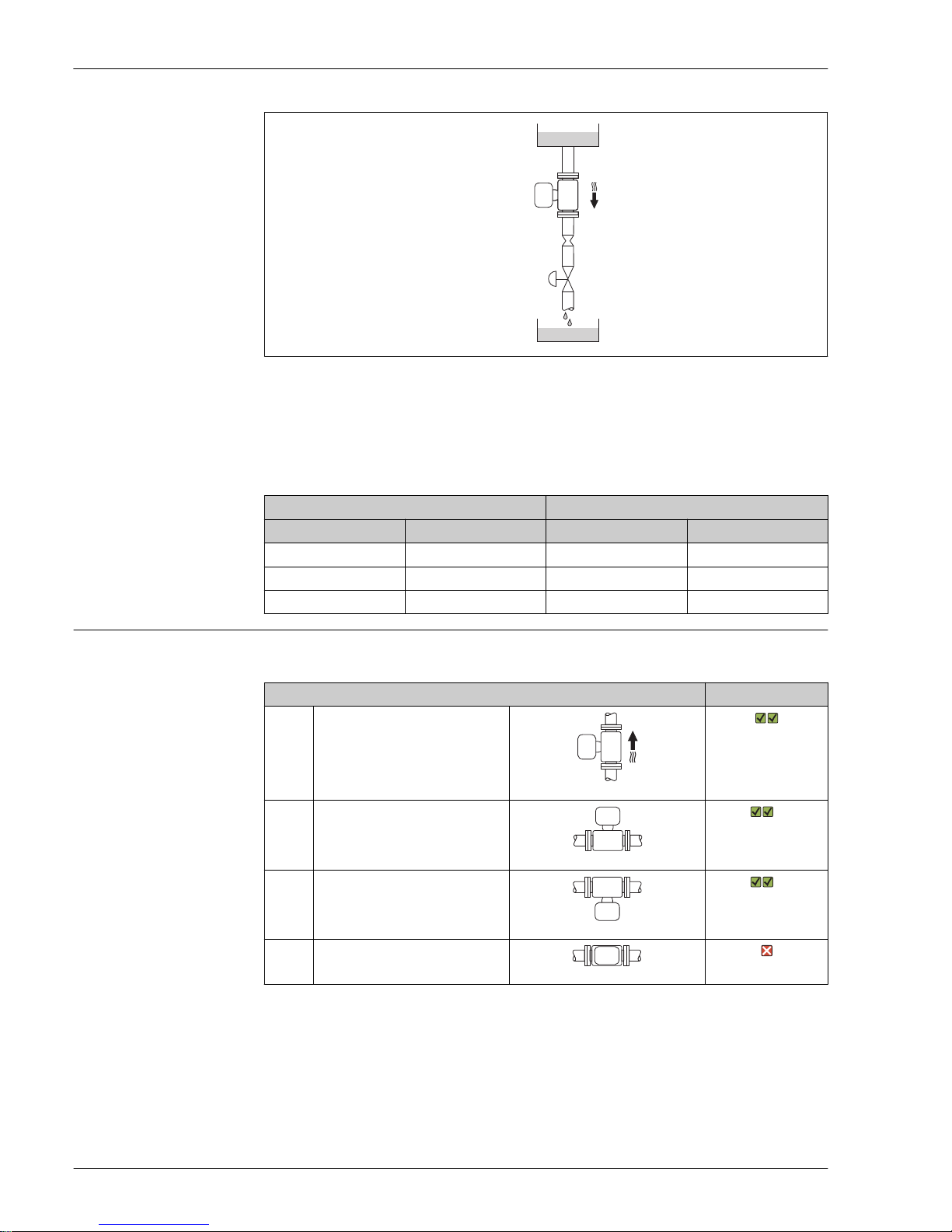
Orientation
The direction of the arrow on the sensor nameplate helps you to install the sensor according to the
flow direction (direction of medium flow through the piping).
Orientation Recommendation
A Vertical orientation
A0015591
B Horizontal orientation, transmitter
head up
A0015589
1)
Exception:
→ 7, 19
C Horizontal orientation, transmitter
head down
A0015590
2)
Exception:
→ 7, 19
D Horizontal orientation, transmitter
head at side
A0015592
1) Applications with low process temperatures may reduce the ambient temperature. To maintain the
minimum ambient temperature for the transmitter, this orientation is recommended.
2) Applications with high process temperatures may increase the ambient temperature. To maintain the
maximum ambient temperature for the transmitter, this orientation is recommended.
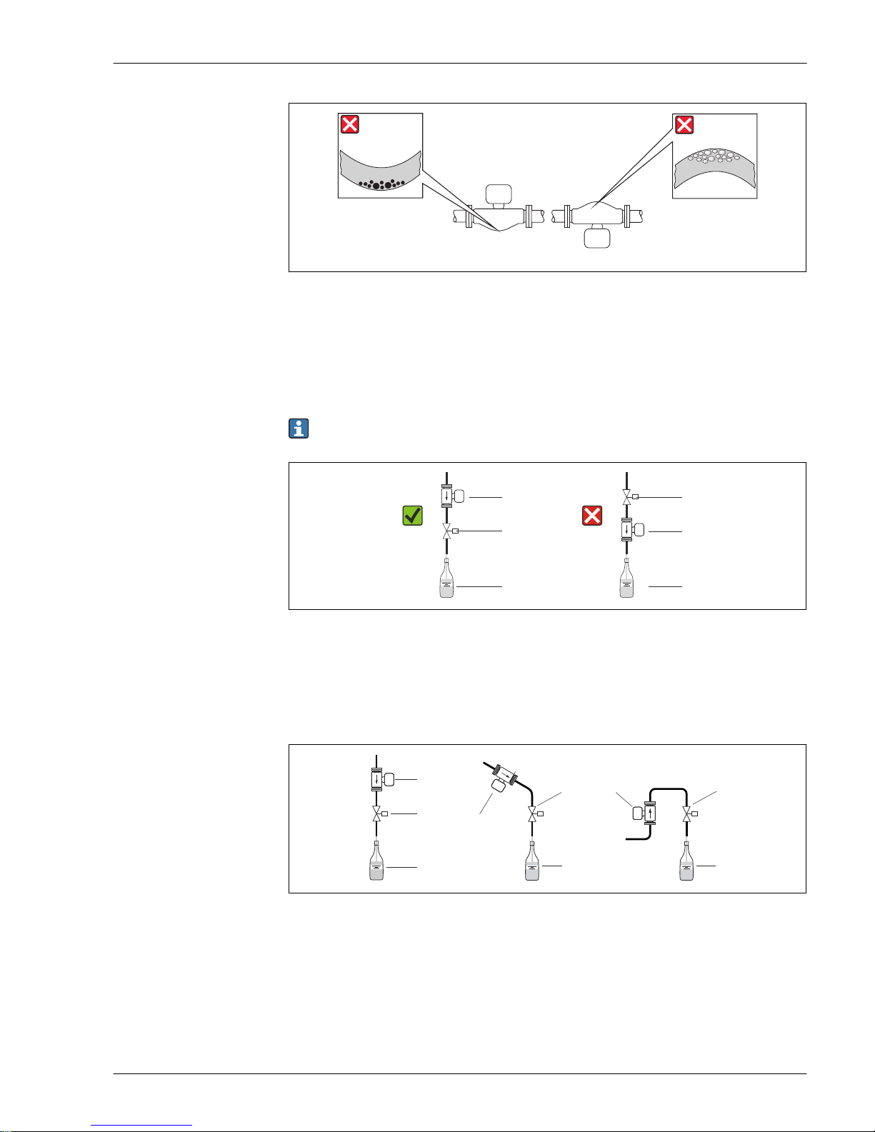
If a sensor is installed horizontally with a curved measuring tube, match the position of the sensor to
the fluid properties.
Page 19
Dosimass
Endress+Hauser 19
1 2
A0014057
7 Orientation of sensor with curved measuring tube
1 Avoid this orientation for fluids with entrained solids: Risk of solids accumulating.
2 Avoid this orientation for outgassing fluids: Risk of gas accumulating.
Valves
Never install the sensor downstream from a filling valve. If the sensor is completely empty this
corrupts the measured value.
Correct measurement is only possible if the pipe is completely full. Perform sample fillings
before commencing filling in production.
1
2
2
1
3
3
A0003768
1 Measuring device
2 Filling valve
3 Container
Filling systems
The pipe system must be completely full to ensure optimum measurement.
1
2
1
2
1
2
3 3 3
A0003795
8 Filling system
1 Measuring device
2 Filling valve
3 Container
Page 20
Dosimass
20 Endress+Hauser
High temperatures
A0003830
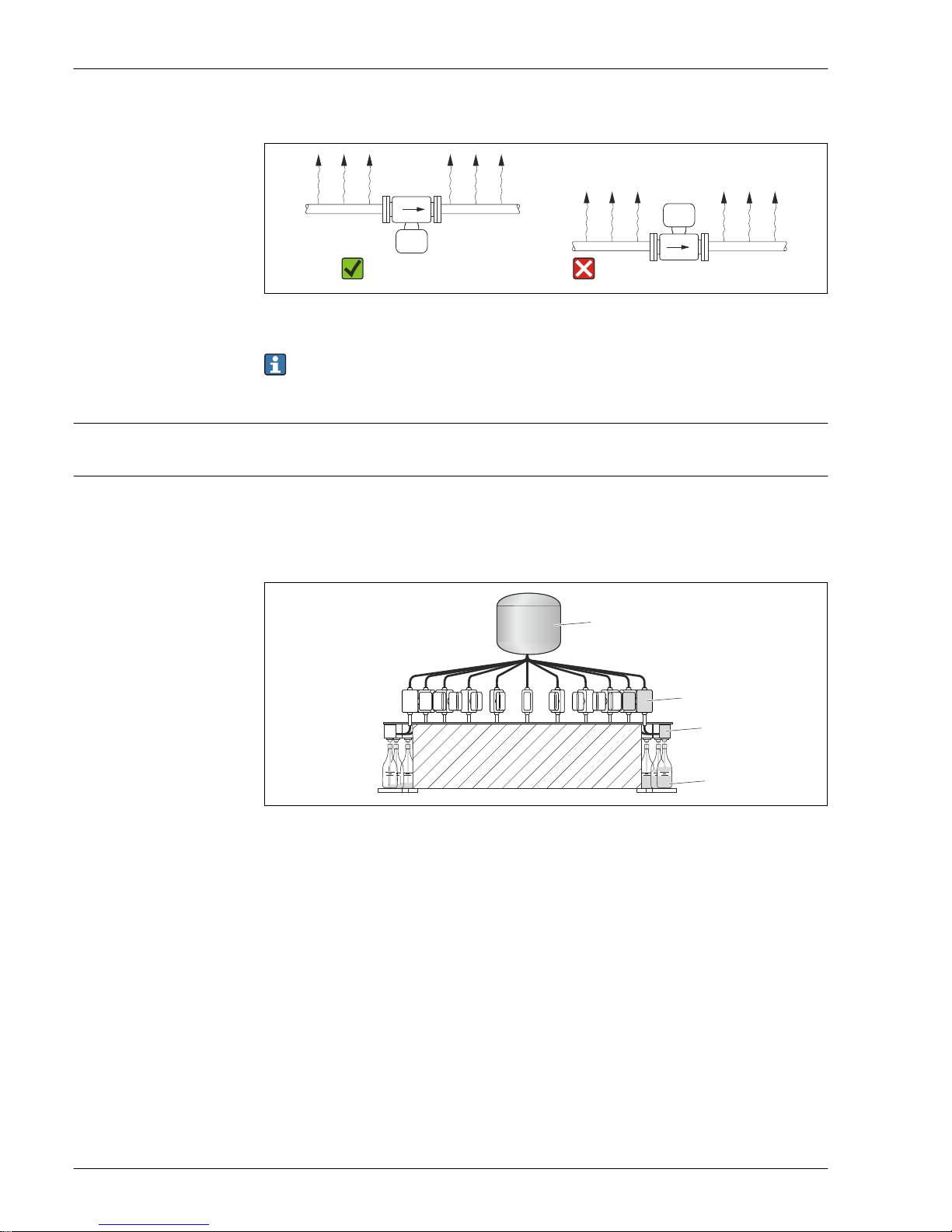
9 Recommended orientation in the event of strong heat formation
To prevent the electronics from overheating in the event of strong heat formation (e.g. CIP or
SIP cleaning process), install the measuring device with the transmitter part pointing
downwards.
Inlet and outlet runs
No special precautions need to be taken for fittings which create turbulence, such as valves, elbows
or T-pieces, as long as no cavitation occurs .
Special mounting
instructions
Information for filling systems
Correct measurement is possible only if the piping is completely filled. We therefore recommend that
some test batches be carried out prior to production batching.
Circular filling system
4
3
1
2
A0003761
1 Measuring device
2 Tank
3 Batching valve
4 Vessel
Page 21
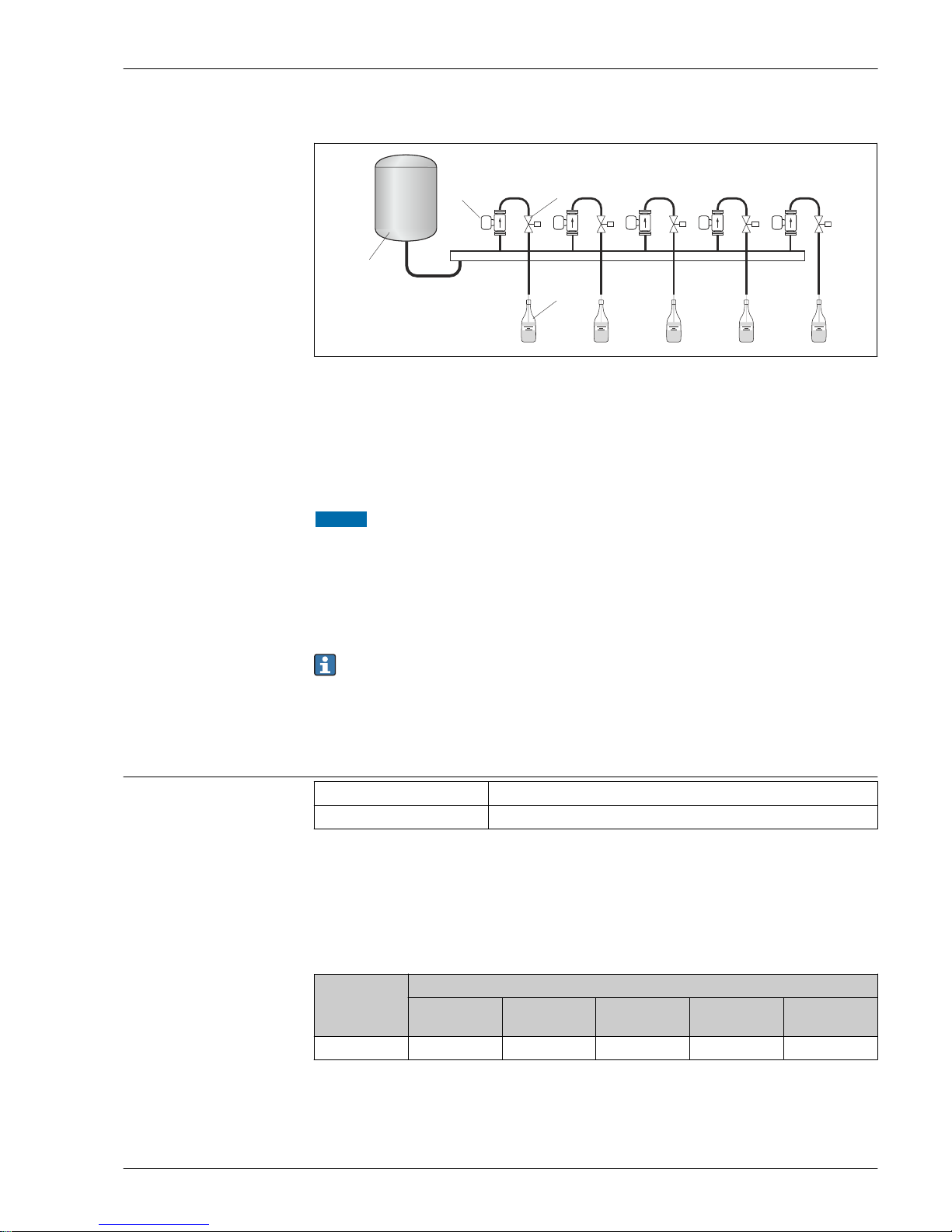
Dosimass
Endress+Hauser 21
Linear filling system
1 3
4
2
A0003762
1 Measuring device
2 Tank
3 Batching valve
4 Vessel
Zero point adjustment
The Sensor adjustment submenu contains parameters required for zero point adjustment.
NOTICE
All Dosimass measuring devices are calibrated in accordance with state-of-the-art technology.
Calibration takes place under reference conditions .
Therefore, a zero point adjustment is generally not required for the Dosimass!
‣
Experience shows that a zero point adjustment is advisable only in special cases.
‣
When maximum accuracy is required and flow rates are very low.
‣
Under extreme process or operating conditions (e.g. very high process temperatures or very highviscosity fluids).
Detailed information on reference conditions→ 15
Environment
Ambient temperature range
Transmitter –40 to +60 °C (–40 to +140 °F)
Sensor –40 to +60 °C (–40 to +140 °F)
Temperature tables
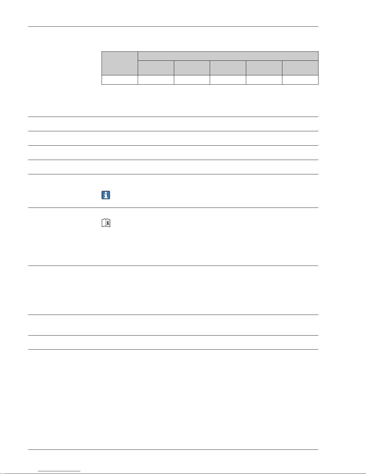
The following interdependencies between the permitted ambient and fluid temperatures apply when
operating the device in hazardous areas:
Ex nA
SI units
T
a
[°C]
Maximum medium temperature T
m
T5
[100 °C]
T4
[135 °C]
T3
[200 °C]
T2
[300 °C]
T1
[450 °C]
60 90 125 125 125 125
Page 22
Dosimass
22 Endress+Hauser
US units
T
a
[°F]
Maximum medium temperature T
m
T5
[212 °F]
T4
[275 °F]
T3
[392 °F]
T2
[572 °F]
T1
[842 °F]
140 194 257 257 257 257
The minimum temperature of the medium is –40 °C (–40 °F).
The minimum ambient temperature is –40 °C (–40 °F).
Storage temperature
–40 to +80 °C (–40 to +176 °F), preferably at +20 °C (+68 °F)
Degree of protection
As standard: IP67, type 4X enclosure
Shock resistance
As per IEC/EN 60068-2-31
Vibration resistance
Acceleration up to 1 g, 10 to 150 Hz, based on IEC/EN 60068-2-6
Interior cleaning
• Cleaning in place (CIP)
• Sterilization in place (SIP)
Observe the maximum medium temperatures → 22
Electromagnetic
compatibility (EMC)
According to IEC/EN 61326
For details, refer to the Declaration of Conformity.
Process
Medium temperature range
Sensor
–40 to +125 °C (–40 to +257 °F)
Cleaning
+150 °C (+302 °F) / 60 min for CIP and SIP processes
Seals
No internal seals
Medium pressure range
(nominal pressure)
max. 40 bar (580 psi), depending on process connection
Density
0 to 5 000 kg/m3 (0 to 312 lb/cf)
Pressure-temperature
ratings
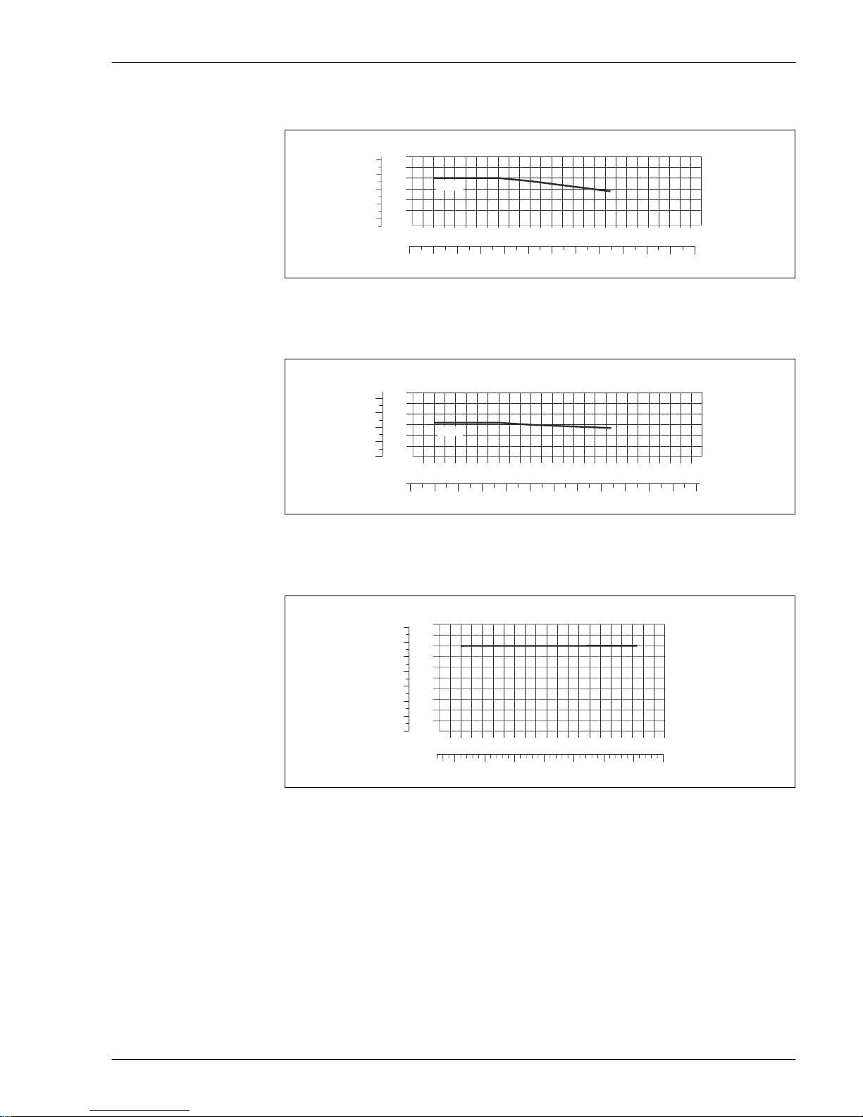
The following pressure-temperature ratings refer to the entire device and not just the process
connection.
Page 23
Dosimass
Endress+Hauser 23
Process connection: flange connection according to EN 1092-1 (DIN 2501)
PN 40
20
30
40
50
[bar][psi]
400
300
500
600
700
-60
-40
-20
0 20
40 60 80 100 120 140 180 200160
[°C]
[°F]
200
0-40
80 120
160
240 280
40 360
320
400-80
A0023105-EN
10 Process connection material: stainless steel 1.4404 (316L/316)
Process connection: sanitary connection according to DIN 11851 / SMS 1145
PN 16
-40
0
-80
40 80 120 160 200 240 280 320 360 400
[°F]
300
400
200
100
0
[psi]
-60
-40
-20
0 20
40 60 80 100 120 140
180
200
160
[°C]
0
10
20
30
[bar]
A0023106-EN
11 Process connection material: stainless steel 1.4404 (316L)
Process connection: coupling according to DIN 11864-1
0
10
20
30
40
50
[bar][psi]
200
400
600
0
300 [°F]250200150100500-50
[°C]150100500-50
A0023108-EN
12 Process connection material: stainless steel 1.4404 (316L)
Page 24
Dosimass
24 Endress+Hauser
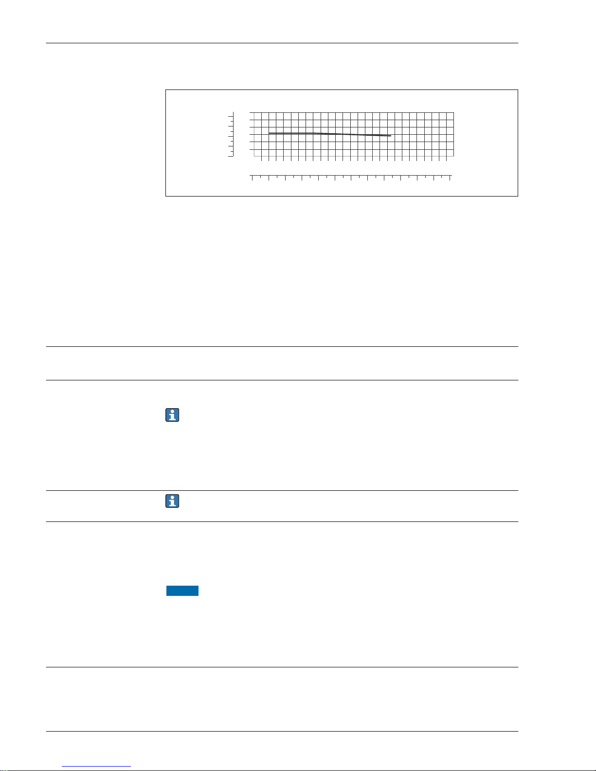
Process connection: coupling according to ISO 2853
0
10
20
30
[bar]
300
400
200
100
0
[psi]
-60
-40
-20
0 20
40 60 80 100 120 140
180
200
160
[°C]
-40
0
-80
40 80 120 160 200 240 280 320 360 400
[°F]
A0023112-EN
13 Process connection material: stainless steel 1.4404 (316L)
Process connection: connection according to DIN 32676 (Clamp)
PS = 16 bar (232 psi)
The clamp connections are suitable up to a maximum pressure of 16 bar (232 psi). Please observe
the operating limits of the clamp and seal used as they could be under 16 bar (232 psi). The clamp
and seal are not included in the scope of supply.
Process connection: Tri-Clamp
The load limit is defined exclusively by the material properties of the Tri-Clamp clamp used. This
clamp is not included in the scope of delivery.
Secondary containment
pressure rating
The housing does not have pressure vessel classification.
Flow limit
Select the nominal diameter by optimizing between the required flow range and permissible pressure
loss.
For an overview of the full scale values for the measuring range, see the "Measuring range"
section → 7
• The minimum recommended full scale value is approx. 1/20 of the maximum full scale value
• For the most common applications, 20 to 50 % of the maximum full scale value can be considered
ideal
• Select a low full scale value for abrasive media (e.g. liquids with entrained solids): Flow velocity <
1 m/s (< 3 ft/s).
Pressure loss
To calculate the pressure loss, use the Applicator sizing tool → 35
Heating
Some fluids require suitable measures to avoid loss of heat at the sensor.
Heating options
• Electrical heating, e.g. with electric band heaters
• Via pipes carrying hot water or steam
• Via heating jackets
NOTICE
Danger of overheating when heating
‣
Ensure that the temperature at the lower end of the transmitter housing does not exceed
80 °C (176 °F)
‣
Ensure that convection takes place on a sufficiently large scale at the transmitter neck.
‣
Ensure that a sufficiently large area of the housing support remains exposed. The uncovered part
serves as a radiator and protects the electronics from overheating and excessive cooling.
Vibrations
The high oscillation frequency of the measuring tubes ensures that the correct operation of the
measuring system is not influenced by plant vibrations.
Page 25
Dosimass
Endress+Hauser 25
Mechanical construction
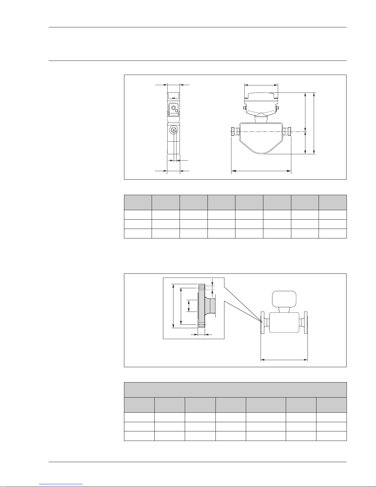
Dimensions in SI units Compact version
di
C
B
A
D
E
+1.5
–2.0
L
(+0.06)
(–0.08)
D
A0008574
DN
[mm]
L
[mm]
A
[mm]
B
[mm]
C
[mm]
D
[mm]
E
[mm]
di
[mm]
8
1)
253 160 93 54 146 5.35
15
1)
267 162 105 54 146 8.30
25
1)
273 167 106 54 146 12.00
1) Depending on the process connection in question
Fixed flange
C
D
A
B
E
L
+1.5 (+0.06)
−2.0 (–0.08)
A0023778
Fixed flange as per EN 1092-1 (DIN 2501
1)
): PN 40
1.4404 (316L): Order code for "Process connection", option D2S
DN
[mm]
L
[mm]
A
[mm]
B
[mm]
C
[mm]
D
[mm]
E
[mm]
8 232 95 65 4 × Ø 14 16 17.3
15 279 95 65 4 × Ø 14 16 17.3
25 329 115 85 4 × Ø 14 18 28.5
1) flange with groove as per EN 1092-1 Form D (DIN 2512N) available
Page 26
Dosimass
26 Endress+Hauser
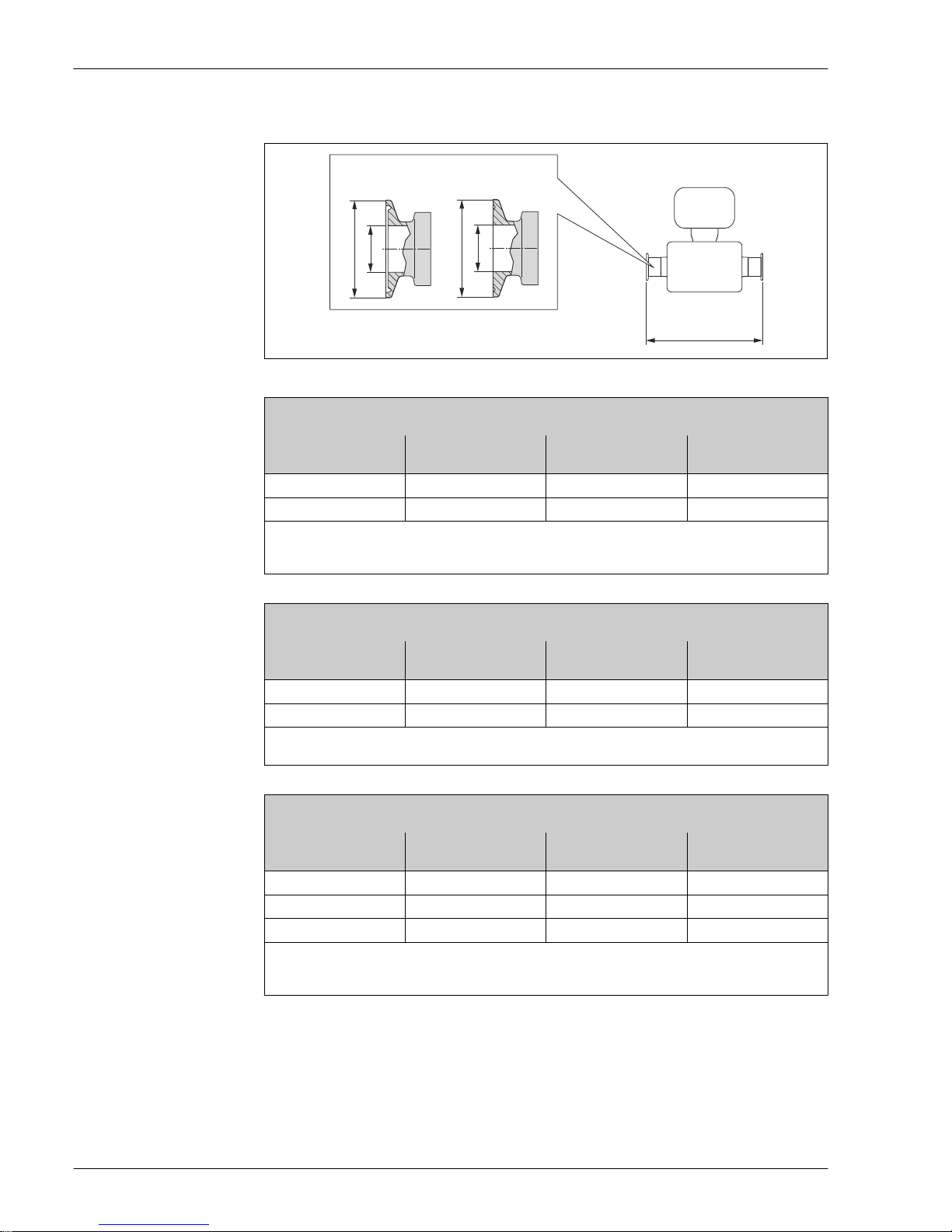
Tri-Clamp
L
+1,5 (+0.06)
-2,0 (-0.08)
A
B
DN 25 (1")DN 8, 15 (¾", ½")
A
B
A0026941
½" Tri-Clamp BS4825-3
1.4404 (316L): Order code for "Process connection", option FUW
DN
[mm]
L
[mm]
A
[mm]
B
[mm]
8 229 25.0 9.5
15 273 25.0 9.5
Surface roughness (3A version):
• Mechanically polished: Ra
max
0.76 µm/150 grit; order code for "Process connection", option FUA
• Electropolished: Ra
max
0.38 µm/240 grit; order code for "Process connection", option FUD
¾" Tri-Clamp
1.4404 (316L): order code for "Process connection", option FWW
DN
[mm]
L
[mm]
A
[mm]
B
[mm]
8 229 25.0 16
15 273 25.0 16
Surface roughness (3A version):
Mechanically polished: Ra
max
0.76 µm/150 grit; order code for "Process connection", option FWA
1" Tri-Clamp
1.4404 (316L): order code for "Process connection", option FTS
DN
[mm]
L
[mm]
A
[mm]
B
[mm]
8 229 50.4 22.1
15 273 50.4 22.1
25 324 50.4 22.1
Surface roughness (3A version):
• Mechanically polished: Ra
max
0.76 µm/150 grit; order code for "Process connection", option FTA
• Electropolished: Ra
max
0.38 µm/240 grit; order code for "Process connection", option FTD
Page 27
Dosimass
Endress+Hauser 27
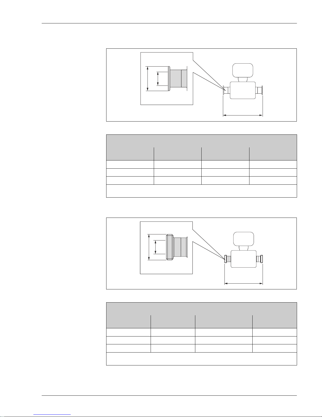
Clamp connection
L
+1,5 (+0.06)
-2,0 (-0.08)
A
B
A0015625
1" clamp DIN 32676
1.4404 (316L): order code for "Process connection", option FDD
DN
[mm]
L
[mm]
A
[mm]
B
[mm]
8 229 34.0 16
15 273 34.0 16
25 324 50.5 26
Surface roughness
Electropolished: Ra
max
0.38 µm/240 grit
Threaded adapter
L
+1,5 (+0.06)
-2,0 (-0.08)
A
B
A0015628
Threaded hygienic connection DIN 11864-1 Form A
1.4404 (316L): order code for "Process connection", option FLW
DN
[mm]
L
[mm]
A
[mm]
B
[mm]
8 229 Rd 28 × 1/8" 10
15 273 Rd 34 × 1/8" 16
25 324 Rd 52 × 1/6" 26
Surface roughness (3A version):
Mechanically polished: Ra
max
0.76 µm/150 grit; order code for "Process connection", option FLA
Page 28
Dosimass
28 Endress+Hauser
L
+1,5 (+0.06)
-2,0 (-0.08)
A
B
A0015628
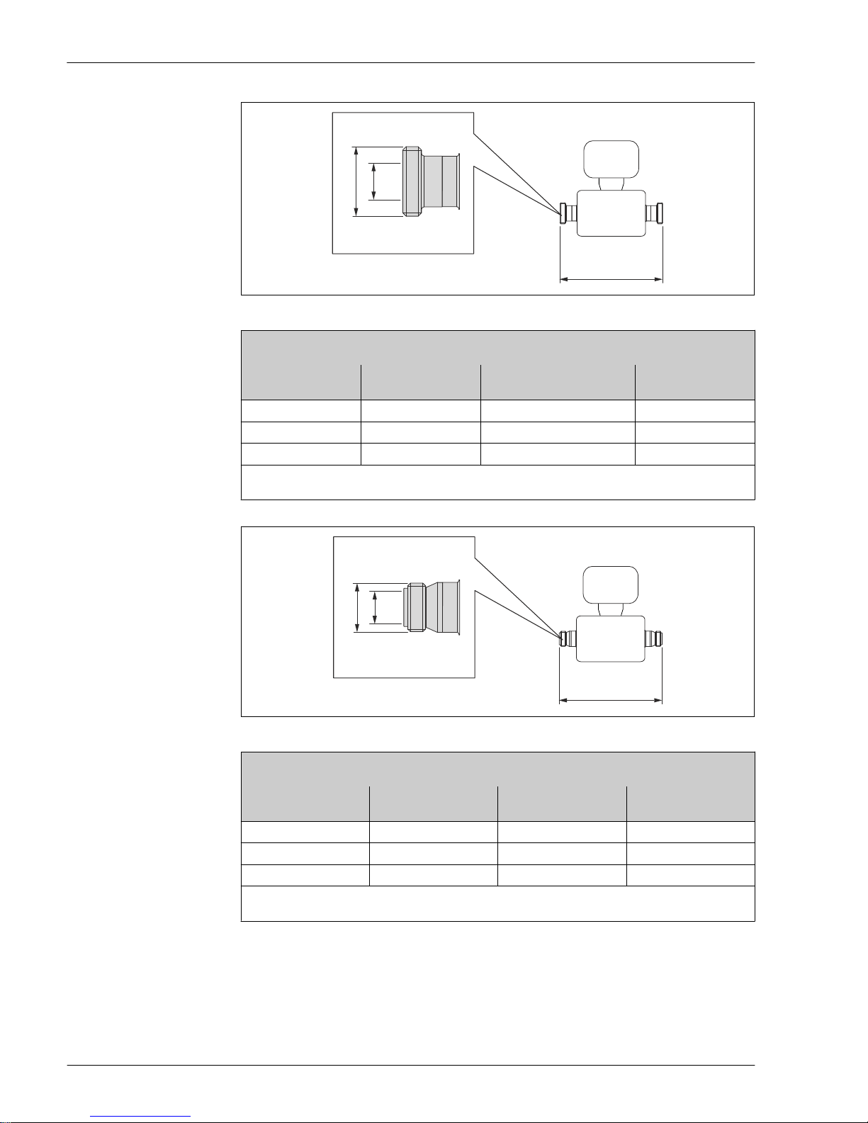
Sanitary connection DIN 11851
1.4404 (316L): order code for "Process connection", option FMW
DN
[mm]
L
[mm]
A
[mm]
B
[mm]
8 229 Rd 34 × 1/8" 16
15 273 Rd 34 × 1/8" 16
25 324 Rd 52 × 1/6" 26
Surface roughness (3A version):
Mechanically polished: Ra
max
0.76 µm/150 grit; order code for "Process connection", option FMA
L
+1,5 (+0.06)
-2,0 (-0.08)
A
B
A0015623
Threaded hygienic connection ISO 2853
1.4404 (316L): order code for "Process connection", option FJW
DN
[mm]
L
[mm]
A
1)
[mm]
B
[mm]
8 229 37.13 22.6
15 273 37.13 22.6
25 324 37.13 22.6
Surface roughness (3A version):
Mechanically polished: Ra
max
0.76 µm/150 grit; order code for "Process connection", option FJA
1) Max. thread diameter as per ISO 2853 Annex A
Page 29
Dosimass
Endress+Hauser 29
L
+1,5 (+0.06)
-2,0 (-0.08)
A
B
A0015628
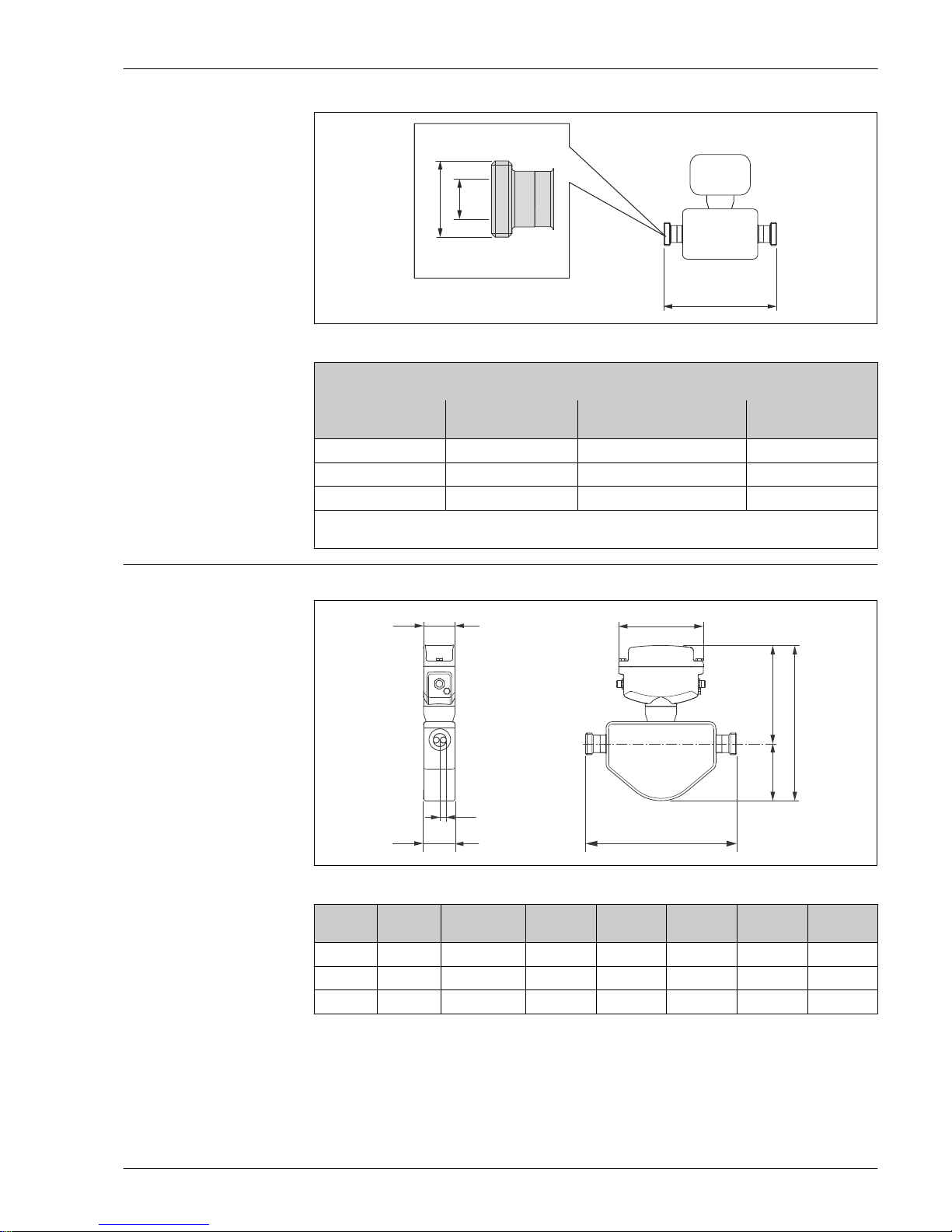
Threaded hygienic connection SMS 1145
1.4404 (316L): order code for "Process connection", option FSW
DN
[mm]
L
[mm]
A
[mm]
B
[mm]
8 229 Rd 40 x 1/6" 22.5
15 273 Rd 40 x 1/6" 22.5
25 324 Rd 40 x 1/6" 22.5
Surface roughness (3A version):
Mechanically polished: Ra
max
0.76 µm/150 grit; order code for "Process connection", option FSA
Dimensions in US units Compact version
di
C
B
A
D
E
+1.5
–2.0
L
(+0.06)
(–0.08)
D
A0008574
DN
[in]
L
[in]
A
[in]
B
[in]
C
[in]
D
[in]
E
[in]
di
[in]
³⁄₈
1)
9.96 6.30 3.66 2.13 5.75 0.21
¹⁄₂
1)
10.50 6.38 4.13 2.13 5.75 0.33
1
1)
10.80 6.57 4.17 2.13 5.75 0.47
1) Depending on the process connection in question
Page 30
Dosimass
30 Endress+Hauser
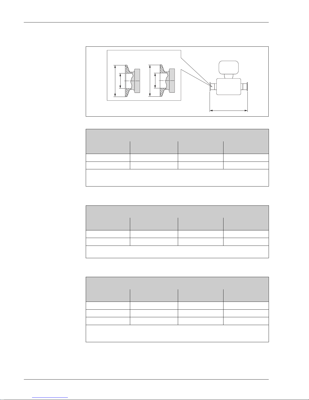
Tri-Clamp
L
+1,5 (+0.06)
-2,0 (-0.08)
A
B
DN 25 (1")DN 8, 15 (¾", ½")
A
B
A0026941
½" Tri-Clamp BS4825-3
1.4404 (316L): Order code for "Process connection", option FUW
1)
DN
[in]
L
[in]
A
[in]
B
[in]
3/8 9.02 0.98 0.37
½ 10.80 0.98 0.37
Surface roughness (3A version):
• Mechanically polished: Ra
max
0.76 µm/150 grit; order code for "Process connection", option FUA
• Electropolished: Ra
max
0.38 µm/240 grit; order code for "Process connection", option FUD
1) 3A version available (Ra ≤ 0.8 µm/150 grit or Ra ≤ 0.4 µm/240 grit)
¾" Tri-Clamp BS4825-3
1.4404 (316L): Order code for "Process connection", option FUW
1)
DN
[in]
L
[in]
A
[in]
B
[in]
3/8 9.02 0.98 0.63
½ 10.80 0.98 0.63
Surface roughness (3A version):
Mechanically polished: Ra
max
0.76 µm/150 grit; order code for "Process connection", option FWA
1) 3A version available (Ra ≤ 0.8 µm/150 grit)
1" Tri-Clamp BS4825-3
1.4404 (316L): order code for "Process connection", option FTS
1)
DN
[in]
L
[in]
A
[in]
B
[in]
3/8 9.02 1.98 0.87
½ 10.80 1.98 0.87
1 12.80 1.98 0.87
Surface roughness (3A version):
• Mechanically polished: Ra
max
0.76 µm/150 grit; order code for "Process connection", option FTA
• Electropolished: Ra
max
0.38 µm/240 grit; order code for "Process connection", option FTD
1) 3A version available (Ra ≤ 0.8 µm/150 grit or Ra ≤ 0.4 µm/240 grit)
Page 31
Dosimass
Endress+Hauser 31
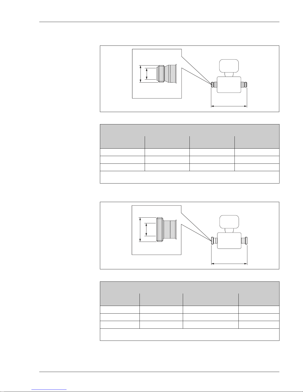
Threaded adapter
L
+1,5 (+0.06)
-2,0 (-0.08)
A
B
A0015623
Threaded hygienic connection ISO 2853
1.4404 (316L): order code for "Process connection", option FJW
DN
[in]
L
[in]
A
1)
[in]
B
[in]
³⁄₈ 9.02 1.46 0.89
½ 10.80 1.46 0.89
1 12.80 1.46 0.89
Surface roughness (3A version):
Mechanically polished: Ra
max
0.76 µm/150 grit; order code for "Process connection", option FJA
1) Max. thread diameter as per ISO 2853 Annex A
L
+1,5 (+0.06)
-2,0 (-0.08)
A
B
A0015628
Threaded hygienic connection SMS 1145
1.4404 (316L): order code for "Process connection", option FSW
DN
[in]
L
[in]
A
[in]
B
[in]
³⁄₈ 9.02 Rd 40 × 1/8" 0.89
½ 10.80 Rd 40 × 1/6" 0.89
1 12.80 Rd 40 × 1/6" 0.89
Surface roughness (3A version):
Mechanically polished: Ra
max
0.76 µm/150 grit; order code for "Process connection", option FSA
Page 32
Dosimass
32 Endress+Hauser
Weight Compact version
Weight in SI units
DN [mm] Weight [kg]
8 3.5
15 4.0
25 4.5
Weight in US units
DN [in] Weight [lbs]
³⁄₈ 7.7
½ 8.8
1 9.9
Materials Transmitter housing
• Acid and alkali-resistant outer surface
• Stainless steel 1.4308 (304)
Device plugs
Electrical connection Material
Plug M12x1 • Socket: Stainless steel, 1.4404 (316L)
• Contact housing: Polyamide
• Contacts: Gold-plated brass
Sensor housing
• Acid and alkali-resistant outer surface
• Stainless steel 1.4301 (304)
Measuring tubes
Stainless steel, 1.4539 (904L)
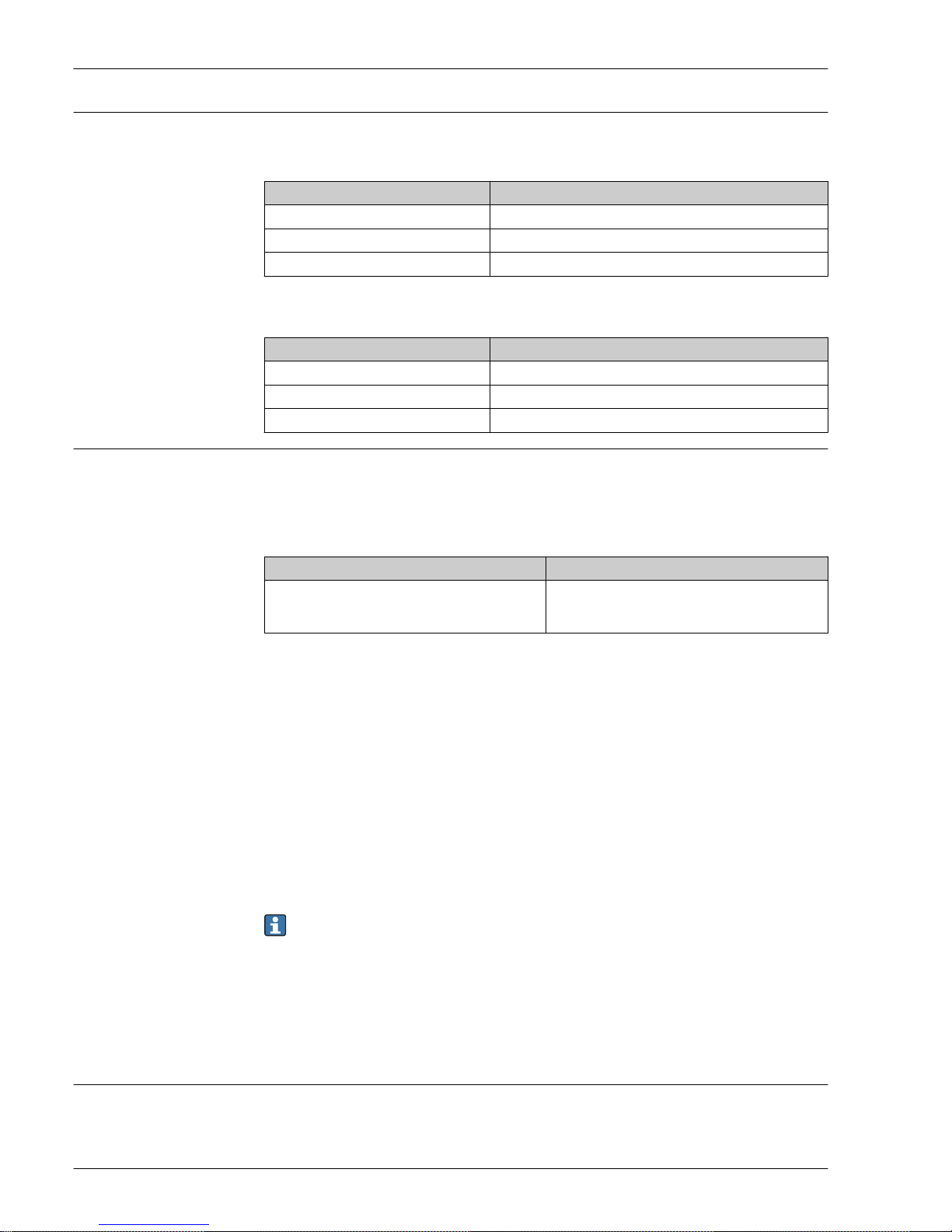
Process connections
• Flanges according to EN (DIN):
Stainless steel, 1.4404 (316/316L)
• Flanges according to DIN 32676:
Stainless steel, 1.4435 (316L)
• All other process connections:
Stainless steel, 1.4404 (316L)
List of all available process connections → 32
Surface quality (parts in contact with medium)
• Ra
max
= 0.4 µm (16 µin)
• Ra
max
= 0.8 µm (32 µin)
Seals
Welded process connections without internal seals
Process connections
Flanges
EN 1092-1 (DIN 2512N)
Page 33
Dosimass
Endress+Hauser 33
Tri-Clamp (OD tubes)
BS4825-3
Clamp with compression fitting
DIN 32676
Threaded adapter
• DIN 11851
• SMS 1145
• ISO 2853
• DIN 11864-1 Form A
For information on the different materials used in the process connections → 32
Operability
Local operation
This device cannot be operated locally using a display or operating elements.
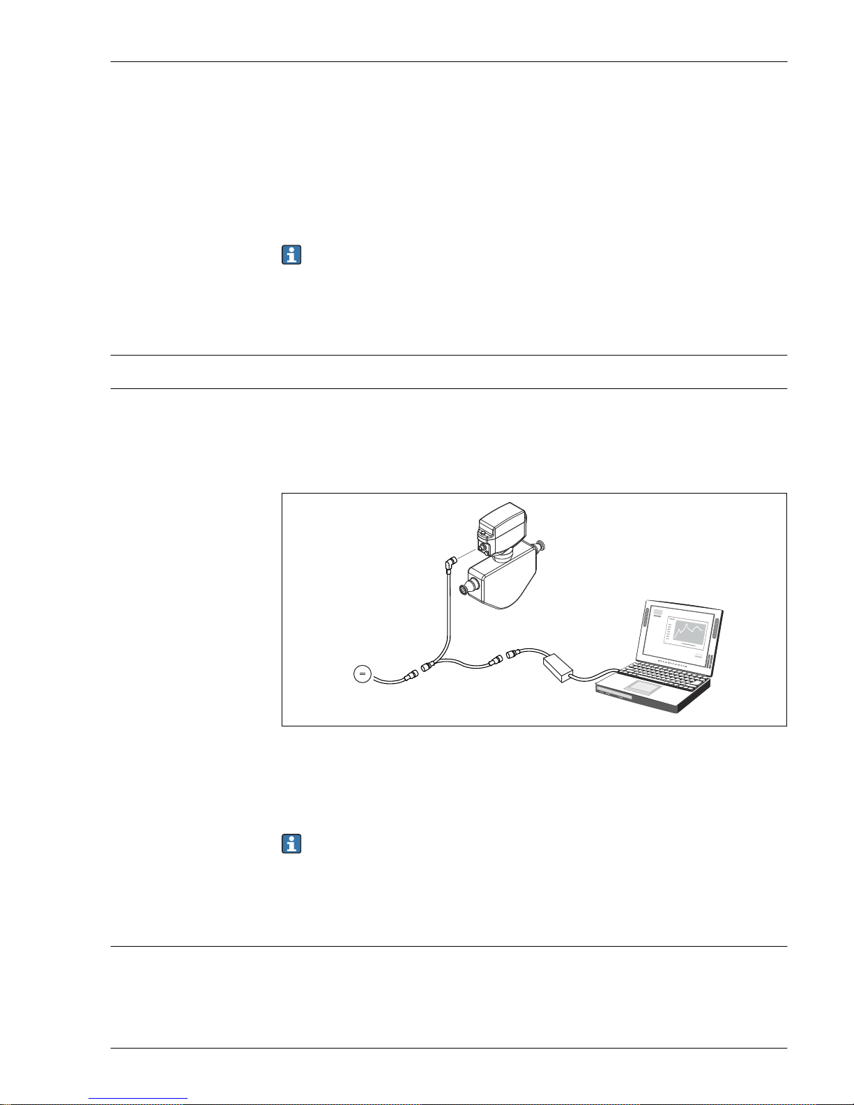
Remote operation Via service adapter and Commubox FXA291
The Endress+Hauser service and configuration software FieldCare or DeviceCare can be used for
operation and configuration.
The device is connected by means of a service adapter and a Commubox FXA291 to the computer's
USB interface.
+
-
1
2
3
4
5
A0007228
1 Supply voltage 24 V DC
2 Service adapter
3 Dosimass
4 Commubox FXA291
5 Computer with "FieldCare" or "DeviceCare" operating tool
The service adapter, cable and Commubox FXA291 are not included in the delivery. These
components can be ordered as accessories → 35.
Certificates and approvals
CE mark
The measuring system is in conformity with the statutory requirements of the applicable EC
Directives. These are listed in the corresponding EC Declaration of Conformity along with the
standards applied.
Endress+Hauser confirms successful testing of the device by affixing to it the CE mark.
Page 34

Dosimass
34 Endress+Hauser
C-Tick symbol
The measuring system meets the EMC requirements of the "Australian Communications and Media
Authority (ACMA)".
Ex approval
The measuring device is certified for use in hazardous areas and the relevant safety instructions are
provided in the separate "Safety Instructions" (XA) document. Reference is made to this document on
the nameplate.
The separate Ex documentation (XA) containing all the relevant explosion protection data is
available from your Endress+Hauser sales center.
ATEX
Currently, the following versions for use in hazardous areas are available:
Ex nA
Category (ATEX) Type of protection
II3G Ex nA IIC T5 to T1 Gc
cCSAus
Currently, the following versions for use in hazardous areas are available:
Class I Division 2 Groups ABCD
Hygienic compatibility
3A approval
Pressure Equipment
Directive
• With the PED/G1/x (x = category) marking on the sensor nameplate, Endress+Hauser confirms
compliance with the "Essential Safety Requirements" specified in Annex I of the Pressure
Equipment Directive 97/23/EC.
• Devices bearing this marking (PED) are suitable for the following types of medium:
– Media in Group 1 and 2 with a vapor pressure greater than, or smaller and equal to0.5 bar
(7.3 psi)
– Unstable gases
• Devices not bearing this marking (PED) are designed and manufactured according to good
engineering practice. They meet the requirements of Art.3 Section 3 of the Pressure Equipment
Directive 97/23/EC. The range of application is indicated in tables 6 to 9 in Annex II of the
Pressure Equipment Directive.
Other standards and
guidelines
• EN 60529
Degrees of protection provided by enclosures (IP code)
• EN 61010-1
Safety Requirements for Electrical Equipment for Measurement, Control and Laboratory Use
• IEC/EN 61326
Emission in accordance with Class A requirements. Electromagnetic compatibility (EMC
requirements).
• EN 61000-4-3 (IEC 1000-4-3)
Operating behavior A with shielded connecting cable possible (shielding connected as short as
possible on both sides), otherwise operating behavior B
• NAMUR NE 21
Electromagnetic compatibility of industrial process and laboratory control equipment
• CAN/CSA C22.2 No. 61010-1-12
Safety Requirements for Electrical Equipment for Measurement, Control and Laboratory Use, Part
1: General Requirements
Page 35
Dosimass
Endress+Hauser 35
Ordering information
Detailed ordering information is available from the following sources:
• In the Product Configurator on the Endress+Hauser website: www.endress.com → Select your
country → Products → Select measuring technology, software or components → Select the product
(picklists: measurement method, product family etc.) → Device support (right-hand column):
Configure the selected product → The Product Configurator for the selected product opens.
• From your Endress+Hauser Sales Center: www.addresses.endress.com
Product Configurator - the tool for individual product configuration
• Up-to-the-minute configuration data
• Depending on the device: Direct input of measuring point-specific information such as
measuring range or operating language
• Automatic verification of exclusion criteria
• Automatic creation of the order code and its breakdown in PDF or Excel output format
• Ability to order directly in the Endress+Hauser Online Shop
Accessories
Various accessories, which can be ordered with the device or subsequently from Endress+Hauser, are
available for the device. Detailed information on the order code in question is available from your
local Endress+Hauser sales center or on the product page of the Endress+Hauser website:
www.endress.com.
Communication-specific
accessories
Accessories Description
FieldCare FDT-based plant asset management tool from Endress+Hauser.
It can configure all smart field units in your system and helps you manage them. By
using the status information, it is also a simple but effective way of checking their
status and condition.
For details, see Operating Instructions BA00027S and BA00059S
DeviceCare Tool for connecting and configuring Endress+Hauser field devices.
For details, see Innovation brochure IN01047S
Commubox FXA291 Connects Endress+Hauser field devices with a CDI interface (= Endress+Hauser
Common Data Interface) and the USB port of a computer or laptop.
For details, see the "Technical Information" document TI405C/07
Adapter connection Adapter connections for installation on other electrical connections:
• Adapter FXA291 (order number: 71035809)
• Adapter RSE8 (order number: 50107169)
RSE8 connection jack, 8-pin adapter (RSE8), 24 V DC, pulse, status
• Adapter RSE5 (order number: 50107168 )
RSE8 connection jack, 5-pin adapter (RSE5), 24 V DC, pulse, status
• Adapter RSE4 (order number: 50107167)
RSE8 connection jack, 4-pin adapter (RSE4), 24 V DC, pulse
Connecting cable RSE8 Cable RKWTN8-56/5 P92, length: 5 m
(Order number: 50107895)
Service-specific accessories
Accessories Description
Applicator Software for selecting and sizing Endress+Hauser measuring devices:
• Calculation of all data required to determine the optimum flowmeter: e.g.
nominal diameter, pressure loss, accuracy or process connections.
• Graphic illustration of the calculation results
Administration, documentation and access to all project-related data and
parameters throughout the entire life cycle of a project.
Applicator is available:
• Via the Internet: https://wapps.endress.com/applicator
• On CD-ROM for local PC installation.
Page 36
Dosimass
36 Endress+Hauser
W@M Life cycle management for your plant
W@M supports you with a wide range of software applications over the entire
process: from planning and procurement, to the installation, commissioning and
operation of the measuring devices. All the relevant information is available for
every measuring device over time entire life cycle, such as the Device status, spare
parts, device-specific documentation.
The application already contains the data of your Endress+Hauser device. Endress
+Hauser also takes care of maintaining and updating the data records.
W@M is available:
• Via the Internet: www.endress.com/lifecyclemanagement
• On CD-ROM for local PC installation.
FieldCare FDT-based plant asset management tool from Endress+Hauser.
It can configure all smart field units in your system and helps you manage them. By
using the status information, it is also a simple but effective way of checking their
status and condition.
For details, see Operating Instructions BA00027S and BA00059S
DeviceCare Tool for connecting and configuring Endress+Hauser field devices.
For details, see Innovation brochure IN01047S
Commubox FXA291 Connects Endress+Hauser field devices with a CDI interface (= Endress+Hauser
Common Data Interface) and the USB port of a computer or laptop.
For details, see "Technical Information" TI00405C
Supplementary documentation
For an overview of the scope of the associated Technical Documentation, refer to the following:
• The CD-ROM provided for the device (depending on the device version, the CD-ROM might
not be part of the delivery!)
• The W@M Device Viewer : Enter the serial number from the nameplate
(www.endress.com/deviceviewer)
• The Endress+Hauser Operations App: Enter the serial number from the nameplate or scan the
2-D matrix code (QR code) on the nameplate.
Standard documentation Brief Operating Instructions
Measuring device Documentation code
Dosimass KA00043D
Operating Instructions
Measuring device Documentation code
Pulse/frequency/status output
Option 3
Modbus RS485
Option 4 and 5
Dosimass BA00097D BA01320D
Description of device parameters
Measuring device Documentation code
Pulse/frequency/status output
Option 3
Modbus RS485
Option 4 and 5
Dosimass GP01050D GP01047D
Page 37

Dosimass
Endress+Hauser 37
Supplementary devicedependent documentation
Safety Instructions
Contents Documentation code
ATEX Ex nA XA00079D
cCSAus FES0232
Registered trademarks
Modbus
®
Registered trademark of SCHNEIDER AUTOMATION, INC.
TRI-CLAMP
®
Registered trademark of Ladish & Co., Inc., Kenosha, USA
Applicator®, FieldCare®, DeviceCare
®
Registered or registration-pending trademarks of the Endress+Hauser Group
Page 38

Page 39

Page 40

www.addresses.endress.com
 Loading...