

Page 1
Technical Information
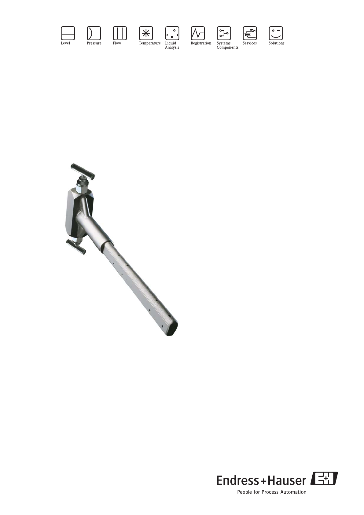
Deltatop
DP71B, DP72B, DP73B
Differential pressure flow measurement with
Pitot tubes and Deltabar differential pressure transmitter
The universal measuring system for steam, gases and liquids
Application
• Flow measurement of gases, steam and liquids
• Nominal diameters from 2" to 21ft
• Nominal diameters from DN 50 to DN 6000
• Pressure up to 6300 psi (420 bar)
• NACE-compliant materials
Deltabar differential pressure transmitter
• Approvals for hazardous area:
FM, CSA, ATEX
• Relevant safety aspects: SIL
• Connection to all common process control systems:
HART, Foundation Fieldbus, Profibus
Your benefits
• Selectable according to the application:
– operational compact version: minimizes installation
costs
– modular remote version: for demanding process
conditions (high temperature, high pressure) and
difficult installation conditions
• Deltabar differential pressure transmitter ready
adjusted
• Display configured for flow rate, differential pressure
or 0 to 100%
• Robust design; no moving parts
TI441P/00/EN/09.09
71102952
Page 2

Table of Contents
Deltatop DP71B, DP72B, DP73B
Function and system design. . . . . . . . . . . . . . . . . . . . . 3
Measuring principle . . . . . . . . . . . . . . . . . . . . . . . . . . . . . . . . . . . 3
Flow calculation . . . . . . . . . . . . . . . . . . . . . . . . . . . . . . . . . . . . . . 4
Sizing and optimization . . . . . . . . . . . . . . . . . . . . . . . . . . . . . . . . 5
"Applicator" selection and sizing tool . . . . . . . . . . . . . . . . . . . . . . 5
Sizing sheet - data sheet . . . . . . . . . . . . . . . . . . . . . . . . . . . . . . . . 5
Selecting the differential pressure transmitter and the measuring
cell . . . . . . . . . . . . . . . . . . . . . . . . . . . . . . . . . . . . . . . . . . . . . . . . 5
Temperature and pressure compensation . . . . . . . . . . . . . . . . . . . 6
Split range (expansion of the measuring range) . . . . . . . . . . . . . . . 8
Flow measurements in liquids or steam . . . . . . . . . . . . . . . . . . . . . 9
Flow measurement in gases . . . . . . . . . . . . . . . . . . . . . . . . . . . . . 9
Mounting positions . . . . . . . . . . . . . . . . . . . . . . . . . . 10
Versions . . . . . . . . . . . . . . . . . . . . . . . . . . . . . . . . . . . . . . . . . . . 10
Flow direction . . . . . . . . . . . . . . . . . . . . . . . . . . . . . . . . . . . . . . 10
Gas measurements . . . . . . . . . . . . . . . . . . . . . . . . . . . . . . . . . . . 10
Liquid or steam measurements . . . . . . . . . . . . . . . . . . . . . . . . . . 11
Installation and process conditions . . . . . . . . . . . . . . 12
Upstream and downstream lengths . . . . . . . . . . . . . . . . . . . . . . . 12
Homogeneity . . . . . . . . . . . . . . . . . . . . . . . . . . . . . . . . . . . . . . . 12
Temperature, pressure . . . . . . . . . . . . . . . . . . . . . . . . . . . . . . . . 12
Practical limits . . . . . . . . . . . . . . . . . . . . . . . . . . . . . . . . . . . . . . 12
Temperature limits of the materials applied . . . . . . . . . . . . . . . . . 13
Pressure-temperature curves for flanges according to
ANSI B16.5-2003 . . . . . . . . . . . . . . . . . . . . . . . . . . . . . . . . . . . 14
Product structure DA73M . . . . . . . . . . . . . . . . . . . . . . . . . . . . . 47
Product structure DA73V . . . . . . . . . . . . . . . . . . . . . . . . . . . . . . 47
Purge unit . . . . . . . . . . . . . . . . . . . . . . . . . . . . . . . . . 48
Usage . . . . . . . . . . . . . . . . . . . . . . . . . . . . . . . . . . . . . . . . . . . . 48
System design . . . . . . . . . . . . . . . . . . . . . . . . . . . . . . . . . . . . . . 48
Mounting . . . . . . . . . . . . . . . . . . . . . . . . . . . . . . . . . . . . . . . . . 48
Sizing sheet - data sheet . . . . . . . . . . . . . . . . . . . . . . 49
Instructions for completing the sizing sheet - data sheet . . . . . . . 51
Mechanical construction . . . . . . . . . . . . . . . . . . . . . . 16
Probe profile . . . . . . . . . . . . . . . . . . . . . . . . . . . . . . . . . . . . . . . . 16
Design, dimensions . . . . . . . . . . . . . . . . . . . . . . . . . . . . . . . . . . 16
Process connection, mounting nozzle . . . . . . . . . . . . . . . . . . . . . 24
Extension welding socket . . . . . . . . . . . . . . . . . . . . . . . . . . . . . . 24
End support . . . . . . . . . . . . . . . . . . . . . . . . . . . . . . . . . . . . . . . . 24
Differential pressure connection . . . . . . . . . . . . . . . . . . . . . . . . . 25
Integrated temperature sensor . . . . . . . . . . . . . . . . . . . . . . . . . . 26
Overview of the product structures . . . . . . . . . . . . . . 27
Ordering information. . . . . . . . . . . . . . . . . . . . . . . . . 29
Product structure Deltatop DP71B . . . . . . . . . . . . . . . . . . . . . . . 29
Product structure Deltatop DP72B . . . . . . . . . . . . . . . . . . . . . . . 32
Product structure Deltatop DP73B . . . . . . . . . . . . . . . . . . . . . . . 36
Accessories . . . . . . . . . . . . . . . . . . . . . . . . . . . . . . . . 40
Overview . . . . . . . . . . . . . . . . . . . . . . . . . . . . . . . . . . . . . . . . . . 40
Deltatop DA73V: shut-off valve (accessory) . . . . . . . . 41
Version: valve (DA73V-6...) . . . . . . . . . . . . . . . . . . . . . . . . . . . . 41
Deltatop DA73M: manifold (accessory) . . . . . . . . . . . 42
Usage . . . . . . . . . . . . . . . . . . . . . . . . . . . . . . . . . . . . . . . . . . . . . 42
Version: 3-valve, manifold . . . . . . . . . . . . . . . . . . . . . . . . . . . . . 43
Version: 5-valve, manifold . . . . . . . . . . . . . . . . . . . . . . . . . . . . . 44
Version: 3-valve, manifold, IEC61518, both sides . . . . . . . . . . . . 45
Version: 5-valve, manifold, IEC61518, both sides . . . . . . . . . . . . 46
2 Endress+Hauser
Page 3
Deltatop DP71B, DP72B, DP73B
Function and system design
Measuring principle
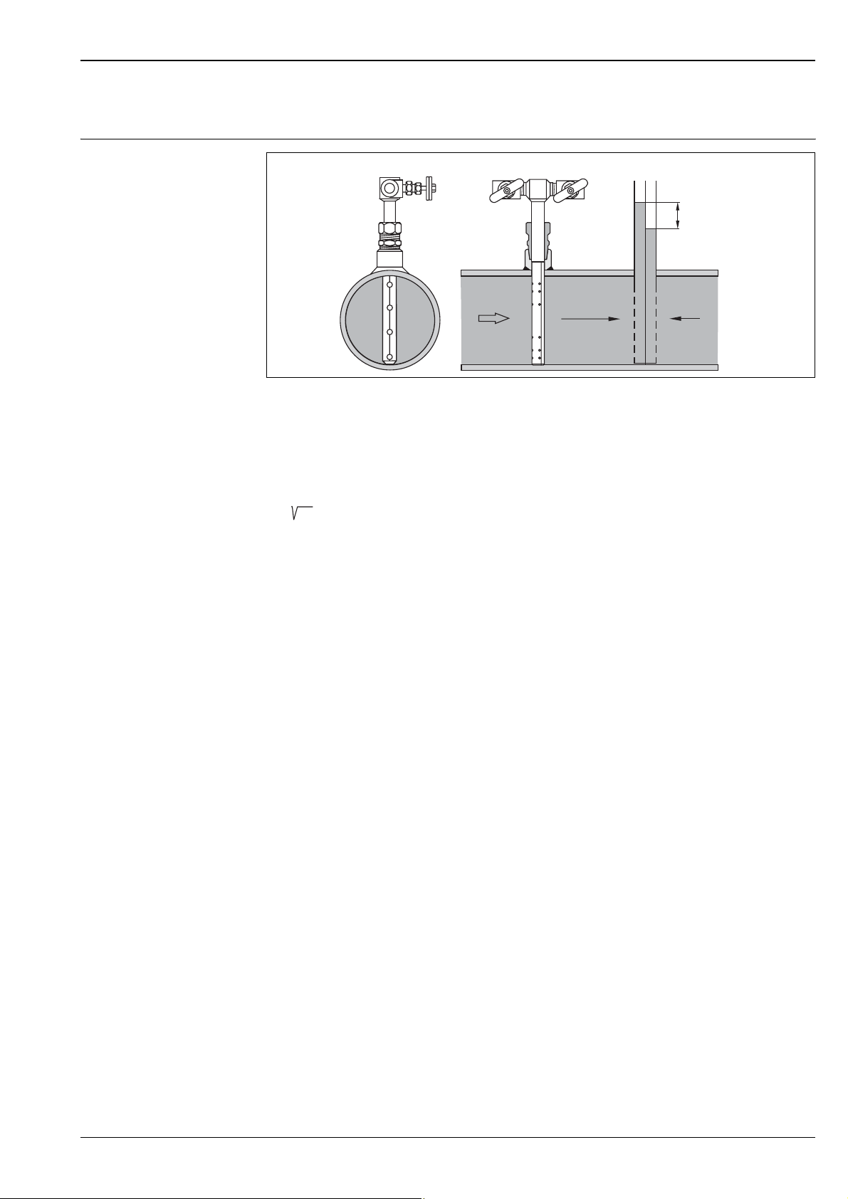
++
The front of the Pitot tube is exposed to the static pressure p
the back of the tube are exposed only to the static pressure p
–
p+p
dyn stat
plus the dynamic pressure p
stat
. The resulting differential pressure Δp can
stat
–
Dp
p
stat
P01-DPxxx-15-00-00-xx-002
. The side and
dyn
be used to calculate the flow rate Q.
The relationship between flow rate (Q) and differential pressure (Δp) is given by a square root function:
Q~
pΔ
Downstream of the Pitot tube the static pressure p
is reduced by the permanent pressure loss Δω. With Pitot
stat
P01-DOxxxxx-15-xx-xx-xx-008
tubes, this pressure loss Δω is much less significant than with other primary elements.
Endress+Hauser 3
Page 4
Deltatop DP71B, DP72B, DP73B
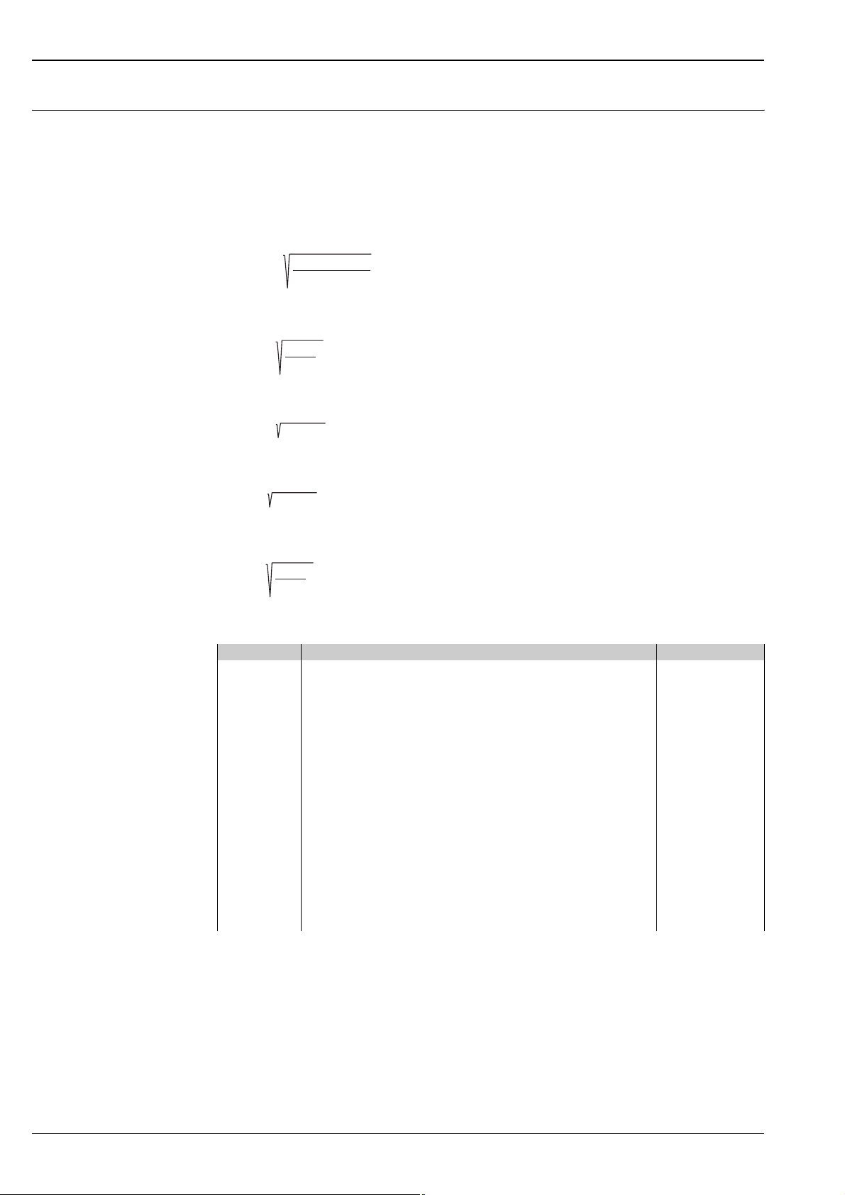
Flow calculation According to the continuity law derived by Bernoulli and the energy equation, the static pressure in the flow
plus the dynamic pressure is equal to a constant throughout the flow:
+ p
p
stat
From this law, the following flow equations can be derived:
Volumetric flow for gases under standard conditions
Q=kAe
Volumetric flow for gases under operating conditions
= const.
dyn
2 pD
P
T
Z
b
vn
r
nn
P
T
Z
n
bbn
Q=kAe
v
2 pD
r
b
Mass flow for gases and steam
Q=
kAe
m
2 pDr
b
Mass flow for liquids
Q=
kA
m
2 pDr
b
Volumetric flow for liquids
Q=kA
v
2 pD
r
b
Definition of the symbols
Symbol Quantity Unit
Δp Differential pressure at the probe profile Pa
ρ
n
ρ
b
A Cross-sectional area of the pipe m
b Width of the probe profile perpendicular to the flow direction m
k k-factor of the Pitot tube 1
κ Isentropic exponent of the gas
P
b
P
n
Q
m
Q
v
Q
vn
T
b
T
n
Z
b
Z
n
ε Expansion factor 1
Medium density at standard conditions kg/m
Medium density at operating conditions kg/m
1)
Operating pressure Pa
Absolute pressure of the gas at standard conditions Pa
Mass flow kg/s
Volumetric flow m3/s
Volumetric flow at standard conditions m3/s
Temperature of the gas at operating conditions K
Temperature of the gas at standard conditions K
Real gas factor at operating conditions 1
Real gas factor at standard conditions 1
3
3
2
1
1) The isentropic exponent is: 1.65 for monoatomic gases; 1.4 for diatomic gases; 1.28 for triatomic gases
4 Endress+Hauser
Page 5

Deltatop DP71B, DP72B, DP73B
Sizing and optimization The exact relationship between differential pressure, flow and pressure loss is described by the k-factor, which
depends on the shape and size of the Pitot tube.
The k-factors of the Deltatop Pitot tubes have been determined and verified in elaborate sample calibrations.
Every Pitot tube is shipped with a calculation sheet. The differential pressure, pressure loss, application limits
and further parameters are calculated based on the customer specifications. For this purpose, a form (Sizing
sheet - data sheet, → ä 49) has to be completed. The user does not have to be involved in complicated sizing
calculations.
"Applicator" selection and sizing tool
Endress+Hauser's Applicator software is a convenient selection and sizing tool for planning processes (for
details, see booklet IN013F). The Applicator program is available free of charge either in the form of a CD or
can be downloaded from the Internet at:
http://www.products.endress.com/applicator
Applicator Sizing Flow
The "Applicator Sizing Flow" module calculates all necessary data for the selected primary device:
• Differential pressure
• Pressure loss
• Measuring uncertainty
• k-factor
• Upstream and downstream straight lengths
• Pressure ratings
• Medium parameters
Additional options
• Sizing sheet - data sheet
• Sizing sheet - calculation sheet
• Determination of the mounting position
Sizing sheet - data sheet To ensure that the Deltatop measuring point exactly matches the requirements of the process, the completed
"Sizing sheet - data sheet" (→ ä 49) has to be attached to the order.
Endress+Hauser uses the data in this form to determine the optimum configuration of the measuring point.
The "Sizing sheet - data sheet" can be generated by the "Applicator" selection and sizing tool.
Selecting the differential pressure transmitter and the measuring cell
If they are ordered together with the primary element, it is possible to order the Deltabar differential pressure
transmitter with a suitable measuring cell and calibration even without knowing the complete calculation data.
Endress+Hauser will select the most suitable measuring cell based on the calculation results for the Pitot tube.
The differential pressure transmitter will be delivered completely configured and preadjusted to the calculated
values.
This allows easy and convenient ordering and commissioning of the measuring point even for less experienced
users.
Deltabar S PMD70/PMD75
Feature of the product structure Option to be selected
40: "Nominal Range; PN" Depending on working pressure PN:
• 78: "Prepared for Deltatop; PN = 2321 psi (160 bar)"
• 88: "Prepared for Deltatop; PN = 6092 psi (420 bar)" (only available for
PMD75)
50: "Calibration; Unit" 8: "Adjusted for Deltatop"
Deltabar M PMD55
Feature of the product structure Option to be selected
070: "Sensor Nominal Value" 88: "Prepared for Deltatop"
090: "Calibration; Unit" 8: "Adjusted for Deltatop"
Endress+Hauser 5
Page 6
Deltatop DP71B, DP72B, DP73B
RMC621
Endress+Hauser
ENDRESS+HAUSER
CERABART
Temperature and pressure compensation
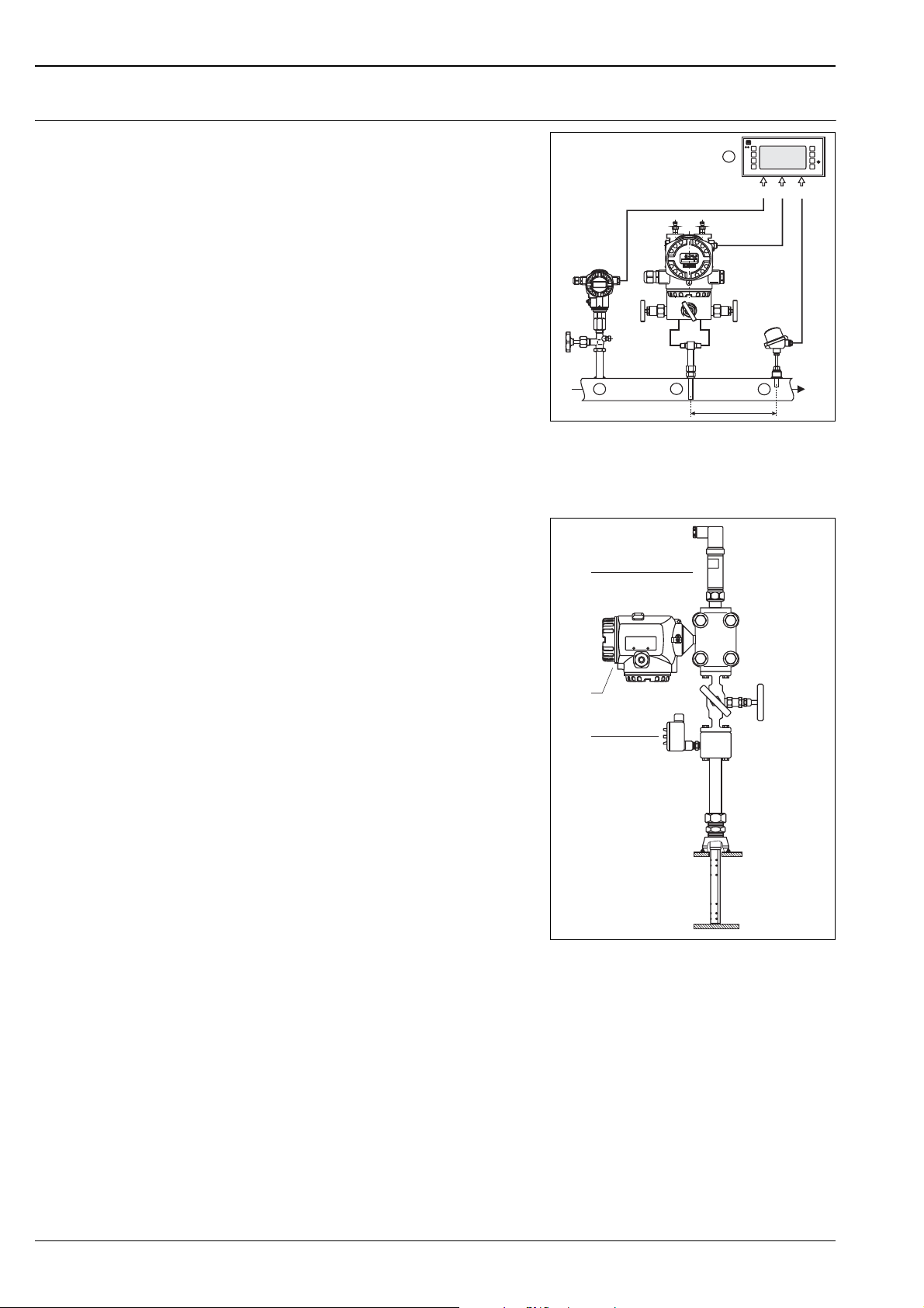
Separate process connections
Two additional probes are required for temperature
and pressure compensation:
• An absolute pressure sensor
This sensor must be mounted on the upstream side
of the Pitot tube.
• A temperature probe
In order to avoid disturbances of the flow profile,
this probe must be mounted on the downstream
side of the Pitot tube. The minimum distance
between the Pitot tube and the temperature probe
is 3D.
(D: diameter of the pipe)
Combined process connection for absolute
pressure, differential pressure and temperature
• Versions of the Deltatop DP72B and DP73B units
are available with an integrated Pt100 temperature
probe
• In the case of Deltabar S, an adapter (e.g. oval
flange PZO) can be used to screw a pressure
transmitter or a pressure sensor into the Deltabar S
flange. The absolute pressure sensor must be
mounted at the "+" side of the Deltabar S.
Endress+Hauser
RMC621
4
p
Dp
1
2
3
3D
P01-DPPxxxxx-15-xx-xx-xx-007
1: Absolute pressure probe
2: Pitot tube and differential pressure transmitter
3: Temperature probe
4: Flow computer
3
1
T
2
P01-DP6xBxxx-14-00-00-xx-001
1: Deltabar S differential pressure transmitter
2: Integrated Pt100 temperature probe
3: Absolute pressure transmitter (has to be ordered
separately)
6 Endress+Hauser
Page 7

Deltatop DP71B, DP72B, DP73B
Calculation of the compensated volume or mass flow
• For steam:
Flow and Energy Manager RMS621 for water and steam from Endress+Hauser;
for details see Technical Information TI092R
• For all media:
Universal Flow and Energy Manager RMC621 for gases, liquids and steam from Endress+Hauser;
for details see Technical Information TI098R
• For all media:
by a PLC;
In this case the compensation calculation has to be programmed by the user.
Calculation formula for temperature and pressure compensation
The starting point for compensation first has to be defined. The starting point is the calculation sheet which
accompanies every primary element. Layout data for a specific operating condition (pressure and temperature)
can be found on the calculation sheet.
The relationship between flow and differential pressure is described by a square root function:
Q=
m
2 pDr
for the mass flow (or volume flow at normal or standard conditions)
and
Q=
v
2 pD
r
for the volume flow
where
ρ = the density of the medium.
If the current output of the Deltabar transmitter is set to flow values, the square root function is already
implemented. Otherwise the square root function must be computed externally, e.g. in a PLC. Please make
sure that the square root function is not applied twice.
Whenever the real operating conditions differ from the conditions used in the calculation sheet, the density of
the gas will change and thus also the calculated flow rate will change according to the above-mentioned
formula.
PPTTZ
21 1
rr=
21
Z
12 2
where
P = absolute pressure
T = absolute temperature (K)
Z = compressibility factor
1 = operating condition according to the calculation sheet
2 = operating condition currently measured
The compensation can now be computed as follows:
Q=Q
21
Q=Q
21
21 1
12 2
PPTTZ
12 2
21 1
for mass flow (or volume flow at standard conditions)
Z
for volume flow
Z
PPTTZ
The compressibility factor Z can be neglected if its value is close to 1. If the compressibility factor is to be
included in the compensation, the value must be determined according to the pressure and temperature
currently measured. Compressibility factors are available in the corresponding literature in tables or graphs or
can be calculated using the Soave-Redlich-Kwong procedure for example.
Endress+Hauser 7
Page 8
Deltatop DP71B, DP72B, DP73B
RMC621
Endress+Hauser
Split range (expansion of the measuring range)
!
!
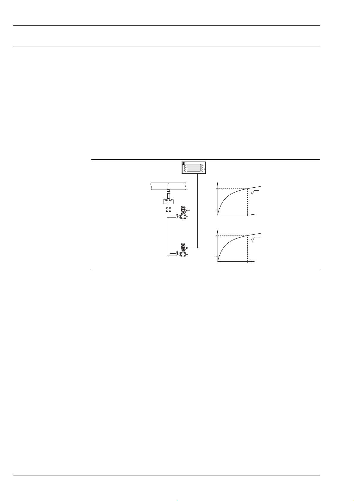
The square root function has a very steep slope in the vicinity of the zero point. Therefore, the measuring range
is limited from below, which results in an operable flow range of typically 6:1 (max. 12:1).
If the differential pressure is high enough, it is possible to increase the range by connecting multiple differential
pressure transmitters with different measuring ranges.
The following Endress+Hauser devices can be used to evaluate the measuring signals simultaneously:
• Flow and Energy Manager RMS621 for water and steam (see Technical Information TI092R)
• Universal Flow and Energy Computer RMC621 for gases, liquids and steam (see Technical Information
TI098R)
Note!
The maximum available operable flow range depends on the differential pressure available.
Note!
The same method can be used to implement redundant measurements.
Example
Endress+Hauser
Q
1800
300
10 360
Δp
Q
300
50
Δp
10
P01-DPPxxxxx-15-xx-xx-xx-008
8 Endress+Hauser
Page 9
Deltatop DP71B, DP72B, DP73B
Flow measurements in liquids or steam
"
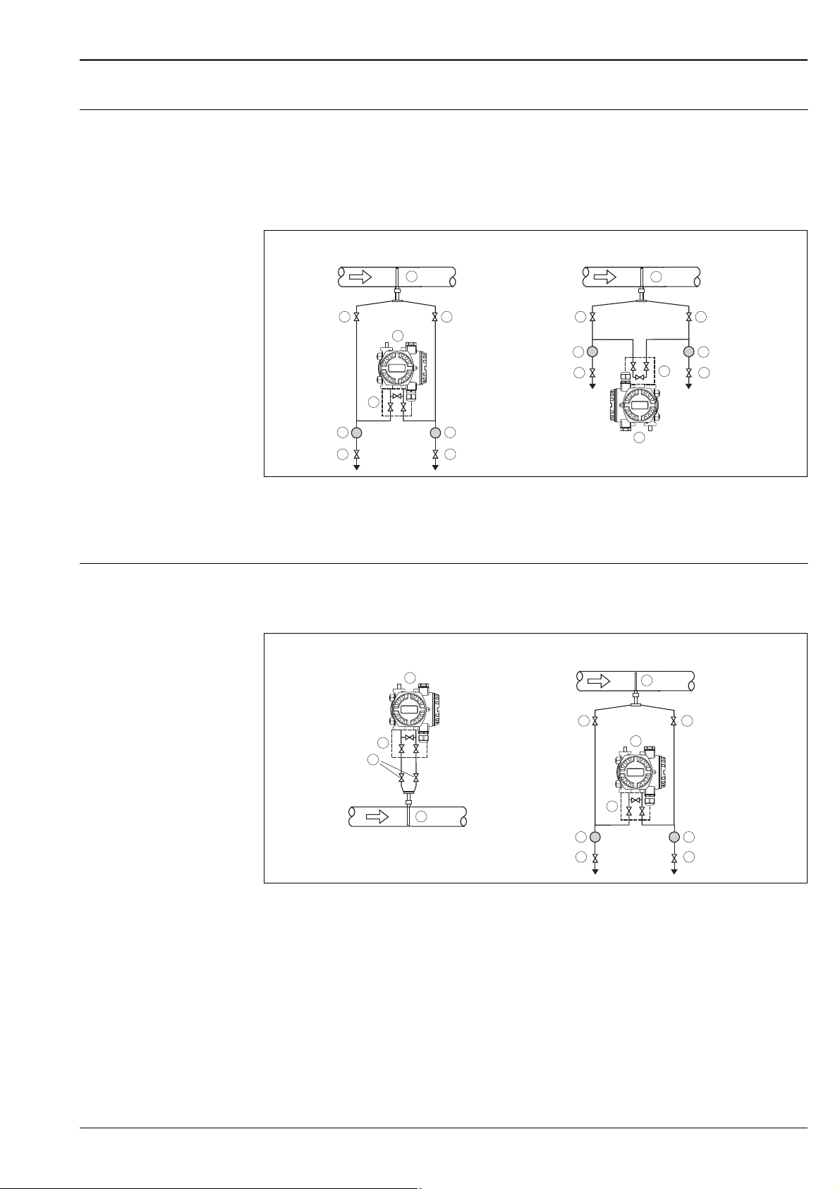
With liquid or steam applications, the transmitter must be mounted below the pipe. All impulse pipes must be
installed with a slope of at least 1:15 to the process connection - coming from the transmitter. This ensures
that trapped air and bubbles rise back to the process pipe and thus do not influence the measurement.
Caution!
With steam applications, the differential pressure transmitter must be located at a sufficient distance to allow
for cooling to meet the transmitter specification. A typical cooling rate is 100 °F per foot (55 °C per 300 mm).
AB
1
2
4
3
+
5
6
A: Preferred configuration; B:Alternative configuration (requires less space; only possible for clean media)
1: Pitot tube; 2: Shut-off valves; 3: Three-valve manifold; 4: Deltabar differential pressure transmitter; 5: Separator;
6: Drain valves
2
–
5
6
2
5
6
1
2
+
–
5
3
6
4
P01-DPxxxxxx-11-xx-xx-xx-005
Flow measurement in gases With gas applications, the transmitter must be mounted above the pipe. All impulse pipes must be installed
with a slope of at least 15:1 to the process connection - coming from the transmitter. This ensures that any
condensate flows back into the process pipe and thus does not influence the measurement.
A
4
2
3
2
+
–
1
5
6
A: Preferred configuration; B: Alternative configuration (if the transmitter cannot be mounted above the pipe; only possible
for clean media)
1: Pitot tube; 2: Shut-off valves; 3: Three-valve manifold; 4: Deltabar differential pressure transmitter; 5: Separator;
6: Drain valve
B
1
2
4
3
+
–
5
6
P01-DPxxxxxx-11-xx-xx-xx-006
Endress+Hauser 9
Page 10
Deltatop DP71B, DP72B, DP73B
Mounting positions
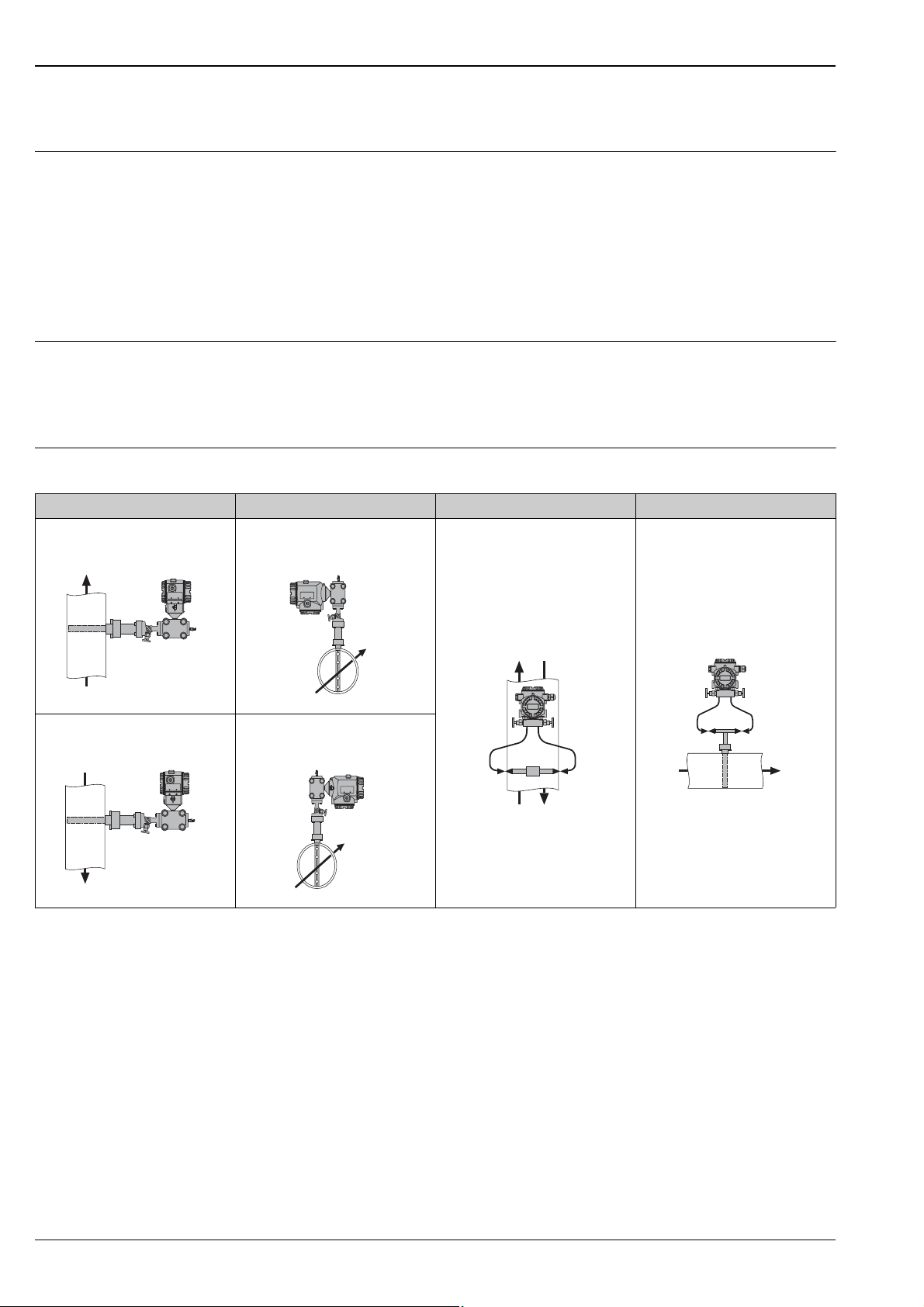
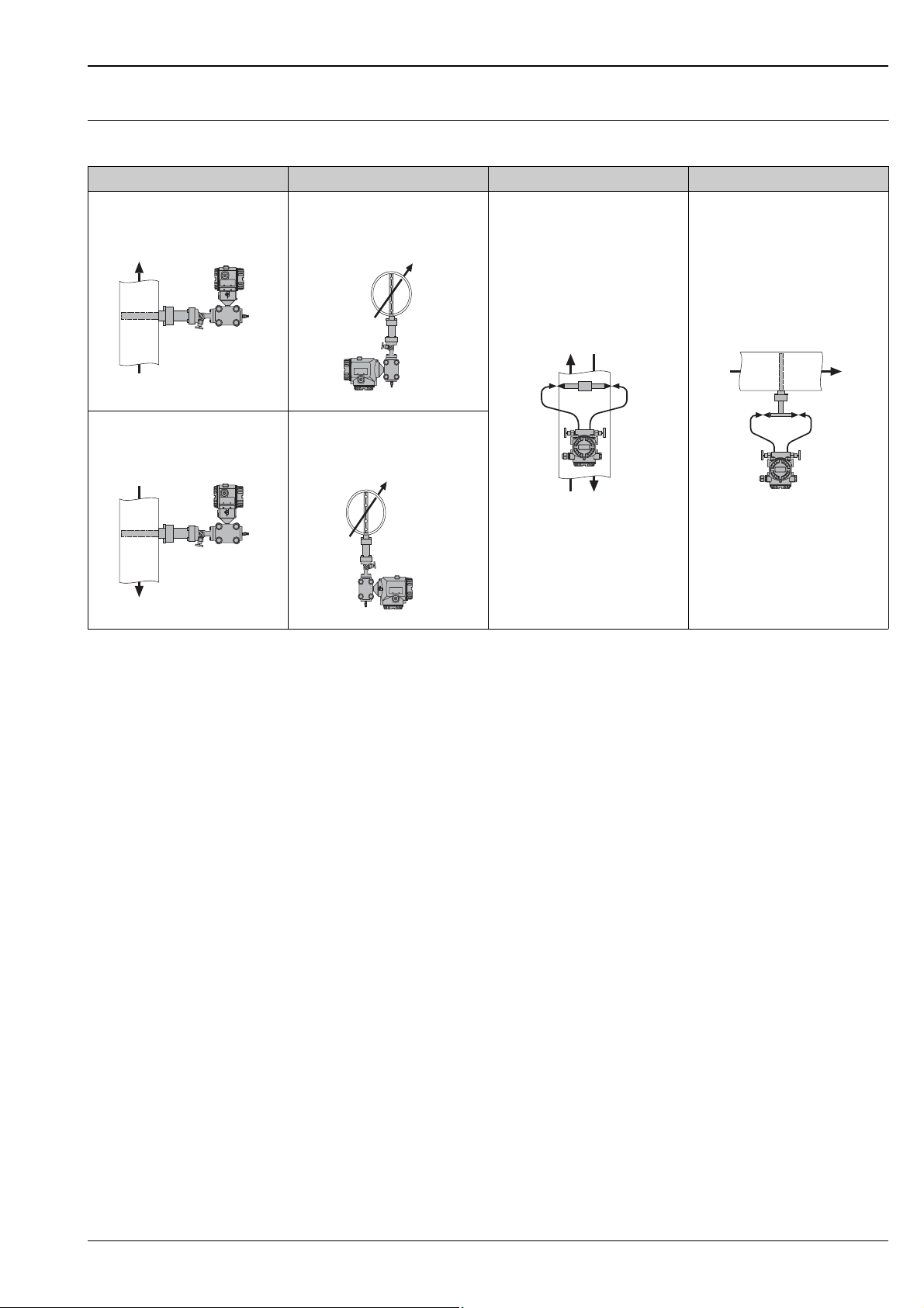
Versions Compact version
With the compact version of the Deltatop, the Pitot tube, the manifold and the transmitter are delivered readymounted. Additional piping and additional valves are not required. Thus, leakage problems are eliminated.
Remote version
With the remote version of the Deltatop, the Pitot tube, the manifold, the shut-off valves and the transmitter
are delivered separately and must be mounted on site. This version is recommended:
• For high process temperatures which make direct transmitter mounting impossible.
• If the transmitter cannot be mounted directly at the Pitot tube due to space restrictions.
Flow direction • The flow direction is indicated by an arrow on the flange plate (compact version) or on the probe head
(remote version).
• "Mounting left" and "Mounting right" refer to the flow direction (see drawings below).
• For compact versions, the transmitter is mounted in such a way that the display can be read in the specified
mounting position and does not need to be rotated.
Gas measurements
Compact; vertical1) Compact; horizontal
flow upwards
DP7xB-CV...
mounting left
DP7xB-CB...
2)
Remote; vertical Remote; horizontal
upwards/downwards
DP7xB-BW...
flow downwards
DP7xB-CU...
P01-DP61Dxxx-11-00-00-xx-001
mounting right
DP7xB-CC...
P01-DP61Dxxx-11-00-00-xx-002
P01-DP61Dxxx-11-00-00-xx-007
P01-DP61Dxxx-11-00-00-xx-008
1) Recommended housing version for the Deltabar S: T14 (for use of the Deltabar display)
2) Recommended housing version for the Deltabar S: T15 (for use of the Deltabar display)
P01-DP61Dxxx-11-00-00-xx-013
top/bottom
DP7xB-BD...
P01-DP61Dxxx-11-00-00-xx-016
10 Endress+Hauser
Page 11
Deltatop DP71B, DP72B, DP73B
Liquid or steam measurements
Compact; vertical
flow upwards
DP7xB-EV... (liquid)
DP7xB-GV... (steam)
1)
Compact; horizontal
mounting left
DP7xB-EB... (liquid)
DP7xB-GB... (steam)
2)
Remote; vertical Remote; horizontal
upwards/downwards
DP7xB-DW... (liquid)
DP7xB-FW... (steam)
flow downwards
DP7xB-EU... (liquid)
DP7xB-GU... (steam)
P01-DP61Dxxx-11-00-00-xx-001
mounting right
DP7xB-EC... (liquid)
DP7xB-GC... (steam)
P01-DP61Dxxx-11-00-00-xx-002
P01-DP61Dxxx-11-00-00-xx-009
P01-DP61Dxxx-11-00-00-xx-010
1) Recommended housing version for the Deltabar S: T14 (for use of the Deltabar display)
2) Recommended housing version for the Deltabar S: T15 (for use of the Deltabar display)
P01-DP61Dxxx-11-00-00-xx-014
top/bottom
DP7xB-DD... (liquid)
DP7xB-FD... (steam)
P01-DP61Dxxx-11-00-00-xx-017
Endress+Hauser 11
Page 12
Installation and process conditions
Deltatop DP71B, DP72B, DP73B
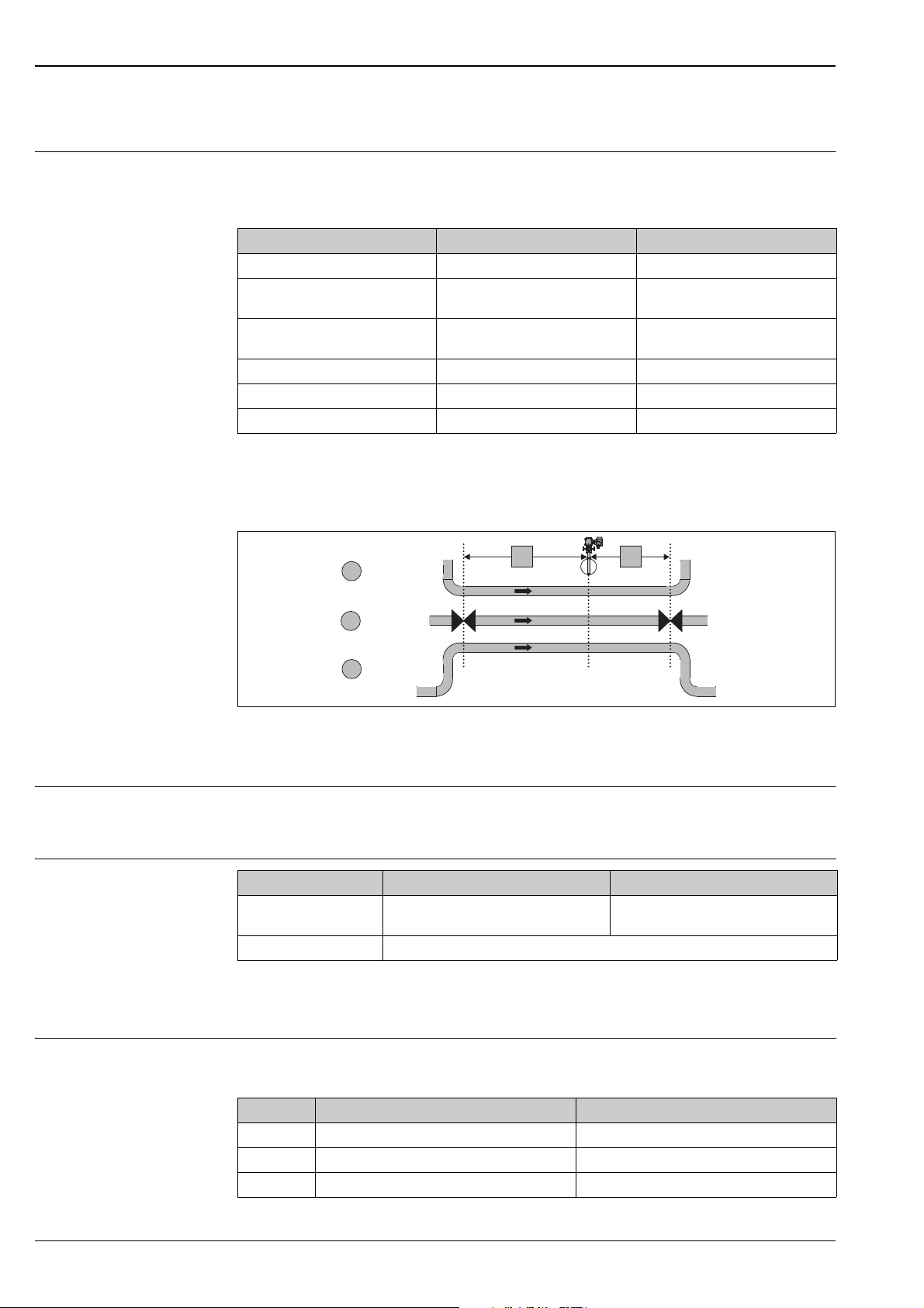
Upstream and downstream lengths
In order to ensure a homogeneous flow profile, it is necessary to mount the Pitot tube at a sufficient distance
to narrowings or bends in the pipe. The required upstream and downstream lengths for different types of
obstacles are summarized in the following table:
Type of obstacle Min. upstream length Min. downstream length
90° bend 7 x D 3 x D
2x90° bend
in the same plane
2x90° bend
in perpendicular planes
Concentric reducer 8 x D 3 x D
Concentric expander 8 x D 3 x D
Ball/gate valve, fully open 24 x D 4 x D
D: Inner pipe diameter
9 x D 3 x D
18 x D 3 x D
Examples (schematic)
a
1
2
b
c
P01-DPxxxxxx-11-xx-xx-xx-008
1: Upstream length; 2: Downstream length;
a: 90° bend; b: Valve, open; c: 2x90° bend
Homogeneity The fluid must be homogeneous. Changes of the state of aggregation (liquid, gas, steam) are not
permissible.
The pipe must always be completely filled.
Temperature, pressure
Max. temperature • For gases, liquids and steam:
Max. pressure 6000 psi (420 bar)
Compact version Remote version
390 °F (200°C)
•With standard material:
approx. 800 °F (427 °C)
Temperature and pressure may not be subject to large fluctuations.
If required, temperature and pressure compensation must be applied for gases and steam (→ ä 6).
Practical limits For a reliable measurement with Pitot tubes, the practical limits are shown in the table below. Equivalent dp
with the respective medium velocity.
Fluid Minimum DP Equivalent velocity
Gas 0.1" (2.5 mm) H
Liquid 1.0" (25 mm) H
Steam 1.5" (38 mm) H
O 15 ft/sec. (4.5 m/sec.)
2
O 2 ft/sec. (0.6 m/sec.)
2
O 32 ft/sec. (9.7 m/sec.)
2
12 Endress+Hauser
Page 13

Deltatop DP71B, DP72B, DP73B
Temperature limits of the materials applied
ASME/AISI/ASTM
Designation Short designation Material code Max. temperature Reference
Steels
C-Si A105 K03504 790 °F (425 °C) ASME B16.5
Heat-resistant steels
C-1/2Mo A182 Gr. F1 K12822 860 °F (465°C) ASME B16.5
1 1/4Cr-1/2Mo-Si A 182 Gr. F11 Cl.2 K11572 1090 °F (590 °C) ASME B16.5
2 1/4Cr-1Mo A 182 Gr. F22 Cl.3 K21590 1090 °F (590 °C) ASME B16.5
Stainless steels
18Cr-8Ni A 182 Gr. F304 S30400 1000 °F (538 °C) ASME B16.5
16Cr-12Ni-2Mo A 182 Gr. F316 S31600 1000 °F (538 °C) ASME B16.5
16Cr-12Ni-2Mo A 182 Gr. F316L S31603 840 °F (450 °C) ASME B16.5
22Cr-5Ni-3Mo-N A 182 Gr. F51 S31803 600 °F (315 °C) ASME B16.5
A 182 Gr. F904L N08904 700 °F (375 °C) ASME B16.5
1) Values for flanges: Maximum recommended temperature for permanent use or maximum temperature specification
of the pressure-temperature ratings.
1)
1)
1)
1)
1)
1)
1)
1)
1)
Plastics
Designation Short designation Max. temperature Reference
PVC Polyvinyl chloride Up to approx. 150 °F (70 °C) Manufacturer
specification
PP Polypropylene Up to approx. 190 °F (90 °C) Manufacturer
PE Polyethylene Up to approx. 170 °F (80 °C) Manufacturer
PVDF Polyvinylidene fluoride Up to approx. 260 °F (130 °C) Manufacturer
PTFE Polytetrafluorethylene Up to approx. 300 °F (150 °C) Manufacturer
specification
specification
specification
specification
Other materials
Designation Short designation Material code Max. temperature Reference
Monel 400 (S-)NiCu 30 Fe 2.4360 790 °F (425 °C) VdTÜV material data sheet
Hastelloy C4 NiMo 16 Cr 16 Ti 2.4610 750 °F (400 °C) VdTÜV material data sheet
Hastelloy C276 NiMo 16 Cr 15 W 2.4819 840 °F (450 °C) VdTÜV material data sheet
Alloy 625 NiCr 22 Mo 9 Nb 2.4856 1650 °F (ca. 900 °C) Key to steel
Alloy 825 NiCr 21 Mo 2.4858 840 °F (450 °C) VdTÜV material data sheet
263
424
400
1)
432
1) Values for forgings: Maximum temperature specification for fatigue strength and 1% creep limit.
!
Note!
All temperature specifications are only guide values. The temperature limits have to be checked in each case.
Depending on the pressure and the medium, they may strongly deviate from these values.
Endress+Hauser 13
Page 14
Deltatop DP71B, DP72B, DP73B
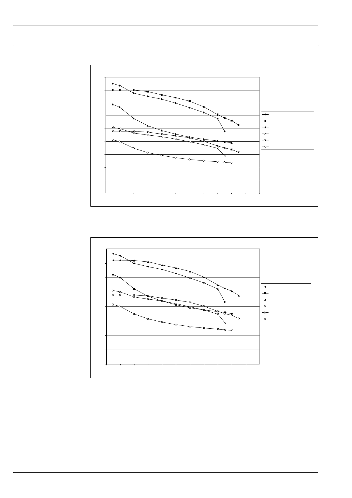
Pressure-temperature curves
for flanges according to
ANSI B16.5-2003
Cl. 2500 /Cl. 1500
P (bar)
450
400
350
300
250
200
150
100
50
0
0 50 100 150 200 250 300 350 400 450 500 550
A105 /Cl.2500
A182Gr.F1 / Cl.2500
316L / Cl.2500
A105 / Cl.1500
A182Gr.F1 / Cl.1500
316L / Cl.1500
T (°C)
P01-DOxxxxxx-05-xx-xx-xx-003
Cl. 900 / Cl. 600
P (bar)
160
140
120
100
80
60
40
20
0
0 50 100 150 200 250 300 350 400 450 500 550
A105 /Cl.900
316L / Cl.900
A182Gr.F1 / Cl.900
A105 / Cl.600
316L / Cl.600
A182Gr.F1 / Cl.600
T (°C)
P01-DOxxxxxx-05-xx-xx-xx-002
14 Endress+Hauser
Page 15
Deltatop DP71B, DP72B, DP73B
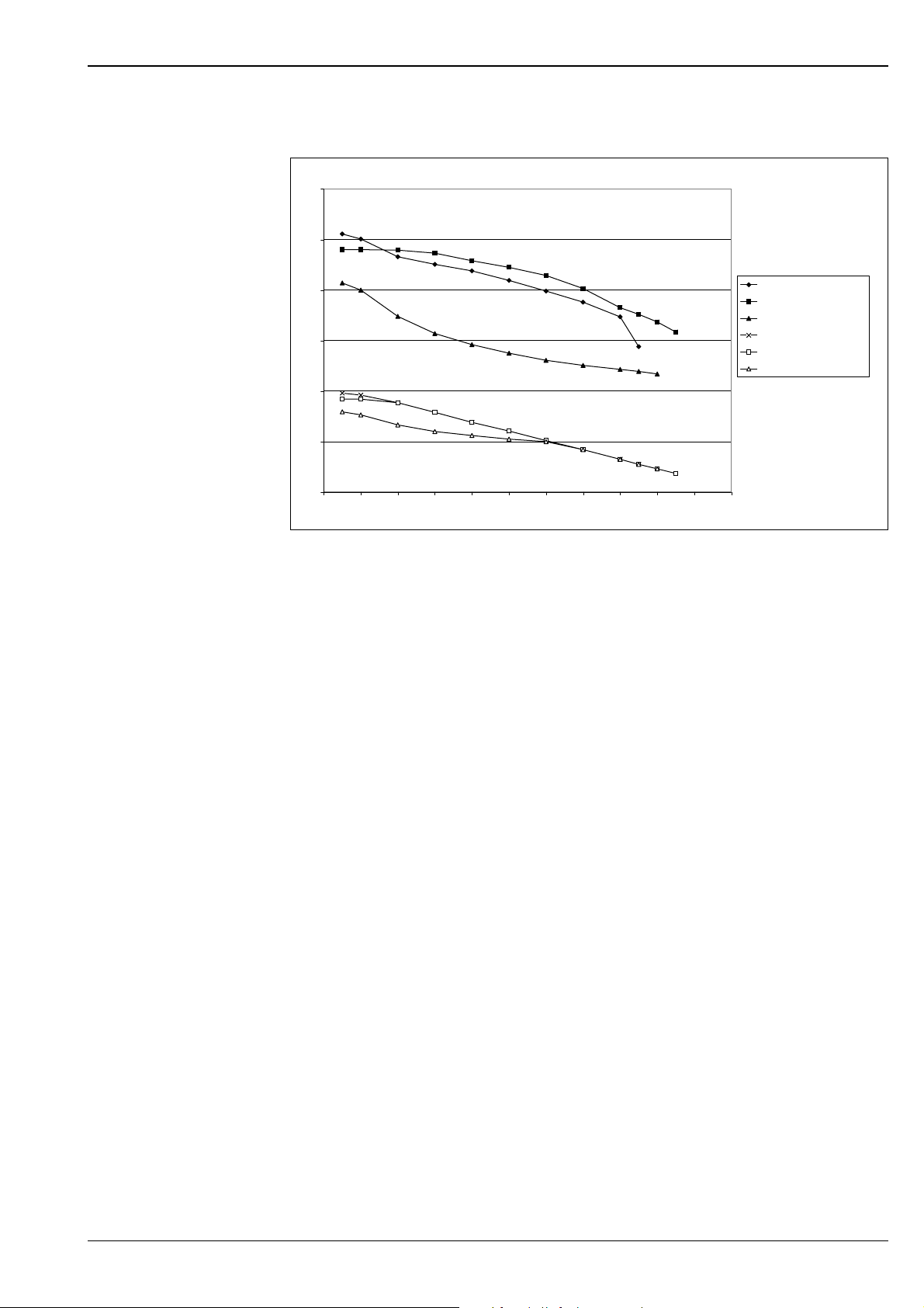
Cl. 300 /Cl. 150
P (bar)
60
50
!
40
30
20
10
0
0 50 100 150 200 250 300 350 400 450 500 550
Note!
The values for 316L refer to the 0.2% yield strength.
A105 /Cl.300
A182Gr.F1 / Cl.300
316L / Cl.300
A105 / Cl.150
A182Gr.F1 / Cl.150
316L / Cl.150
T (°C)
P01-DOxxxxxx-05-xx-xx-xx-001
Endress+Hauser 15
Page 16
Deltatop DP71B, DP72B, DP73B
Mechanical construction
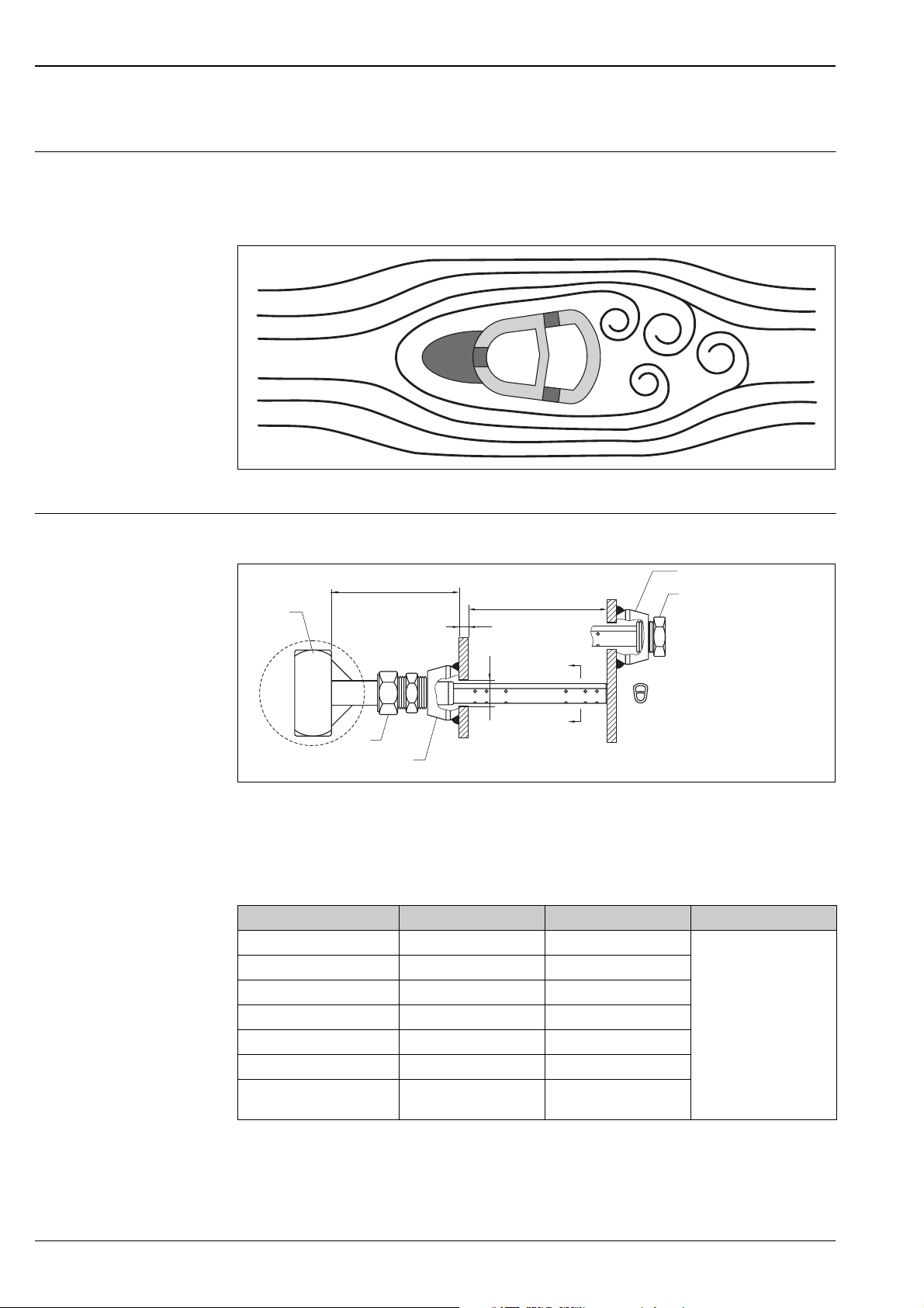
Probe profile Developed from aerospace technology, the Deltatop averaging Pitot flow sensor provides unsurpassed accuracy
and reliability. With its solid one-piece construction and bullet shape, the Deltatop makes flow measurement
clog-free and precise. The unique sensor shape reduces drag and flow-induced vibration. The location of the
low pressure ports eliminates the potential for clogging, hence improving signal stability.
P01-DPxxxxx-15-xx-xx-xx-016
Design, dimensions Process connection: "Pipe > cutting ring"
H
1
2
3
1: Device head
2: Tube fitting
3: Welding socket
4: Welding socket for end support (supplied if end support has been selected in the product structure)
5: Plug for end support (supplied if end support has been selected in the product structure)
DP71B DP72B DP73B
ANSI rating Class 600 Class 300
Sensor diameter 7/16" (11 mm) 7/8" (22 mm)
Dim. "D" drilled hole diameter 1/2" (13 mm) 1" (25 mm)
Tube fitting size 5/8" tube x 3/4" NPT 1" tube x 1" NPT
Welding socket size 3/4" NPT 1" NPT
Dim. "H" 4.0" (102 mm) 5.5" (140 mm)
Pipe size "ID" 2" - 6"
(50 mm - 150 mm)
4
ID
W
D
A
A
6" - 48"
(150 mm - 1200 mm)
A-A
5
P01-DP6xBxxx-06-00-00-xx-001
Not available
!
Note!
The wall thickness "W" and the inner diameter "ID" of the pipe have to be specified when ordering a Deltatop
measuring system.
16 Endress+Hauser
Page 17
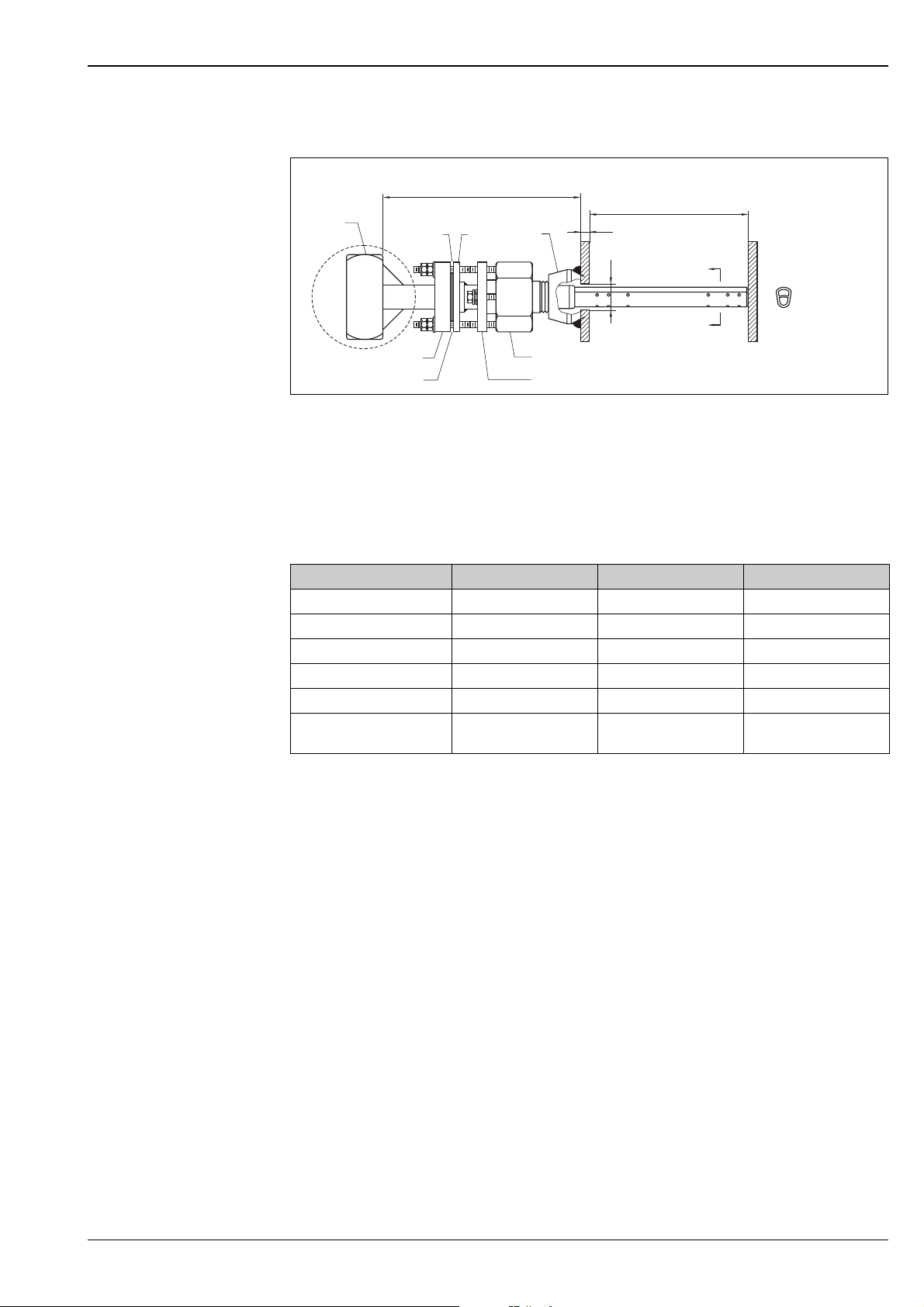
Deltatop DP71B, DP72B, DP73B
Process connection: "Pipe > spring lock"
H
1
48 7
ID
W
D
2
3
1: Device head
2: Load plate
3: Load springs
4: Visual load indication
5: Packing follower
6: Packing body
7: Welding socket
8: Indication ring
DP71B DP72B DP73B
ANSI rating Class 600 Class 600 Class 600
Sensor diameter 7/16" (11 mm) 7/8" (22 mm) 1-3/8" (35 mm)
Dim. "D" drilled hole diameter 1/2" (13 mm) 1" (25 mm) 1-1/2" (39 mm)
Welding socket size 3/4" NPT 1" NPT 2" NPT
Dim. "H" 7.5" (191 mm) 10.2" (259 mm) 11.7" (297 mm)
Pipe size "ID" 2" - 6"
(50 mm - 150 mm)
6
5
6" - 42"
(150 mm - 1050 mm)
A
A
A-A
P01-DP6xBxxx-06-00-00-xx-002
12" - 60"
300 mm - 1500 mm
!
Note!
The wall thickness "W" and the inner diameter "ID" of the pipe have to be specified when ordering a Deltatop
measuring system.
Endress+Hauser 17
Page 18
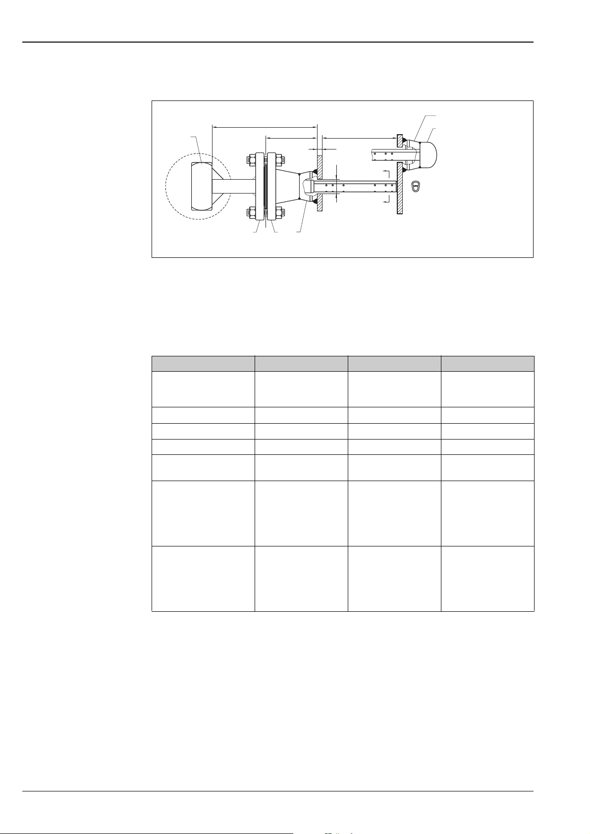
Process connection: "ANSI flange"
Deltatop DP71B, DP72B, DP73B
H
1
2 3 4
1: Device head
2: Sensor flange
3: Spiral wound gasket
4: Weld neck flange
5: Welding socket
6: Welding socket for end support
7: Weld cap for end support
DP71B DP72B DP73B
ANSI class
Sensor diameter 7/16" (11 mm) 7/8" (22 mm) 1-3/8" (35 mm)
Dim. "D" drilled hole diameter 1/2" (13 mm) 1" (25 mm) 1-1/2" (39 mm)
Flange size 1" 1-1/2" 2"
Pipe size "ID" 2" - 6"
Dim. "X" • Class 150:
Dim. "H" • Class 150:
1)
• Class 150
• Class 300
• Class 600
(50 mm - 150 mm)
• Class 300:
• Class 600:
• Class 300:
• Class 600:
XID
W
D
5
• Class 150
• Class 300
• Class 600
6" - 48"
(150 mm - 1200 mm)
• Class 150:
approx. 3.31" (84 mm)
approx. 3.56" (90 mm)
approx. 3.81" (97 mm)
approx. 6.7" (150 mm)
approx. 7.3" (186 mm)
approx. 7.8" (198 mm)
approx. 3.81" (97 mm)
• Class 300:
approx. 4.06" (103 mm)
• Class 600:
approx. 4.38" (111 mm)
• Class 150:
approx. 7.9" (200 mm)
• Class 300:
approx. 8.4" (214 mm)
• Class 600:
approx. 9.1" (230 mm)
A
A
6
7
A-A
P01-DP6xBxxx-06-00-00-xx-007
•Class 150
•Class 300
•Class 600
12" - 192"
(300 mm - 5000 mm)
• Class 150:
approx. 4.06" (103 mm)
• Class 300:
approx. 4.31" (110 mm)
• Class 600:
approx. 4.69" (119 mm)
• Class 150:
approx. 9.3" (235 mm)
• Class 300:
approx. 9.8" (249 mm)
• Class 600:
approx. 10.6" (268 mm)
1) Classes 1500 and 2500 on request
!
Note!
The wall thickness "W" and the inner diameter "ID" of the pipe have to be specified when ordering a Deltatop
measuring system.
18 Endress+Hauser
Page 19
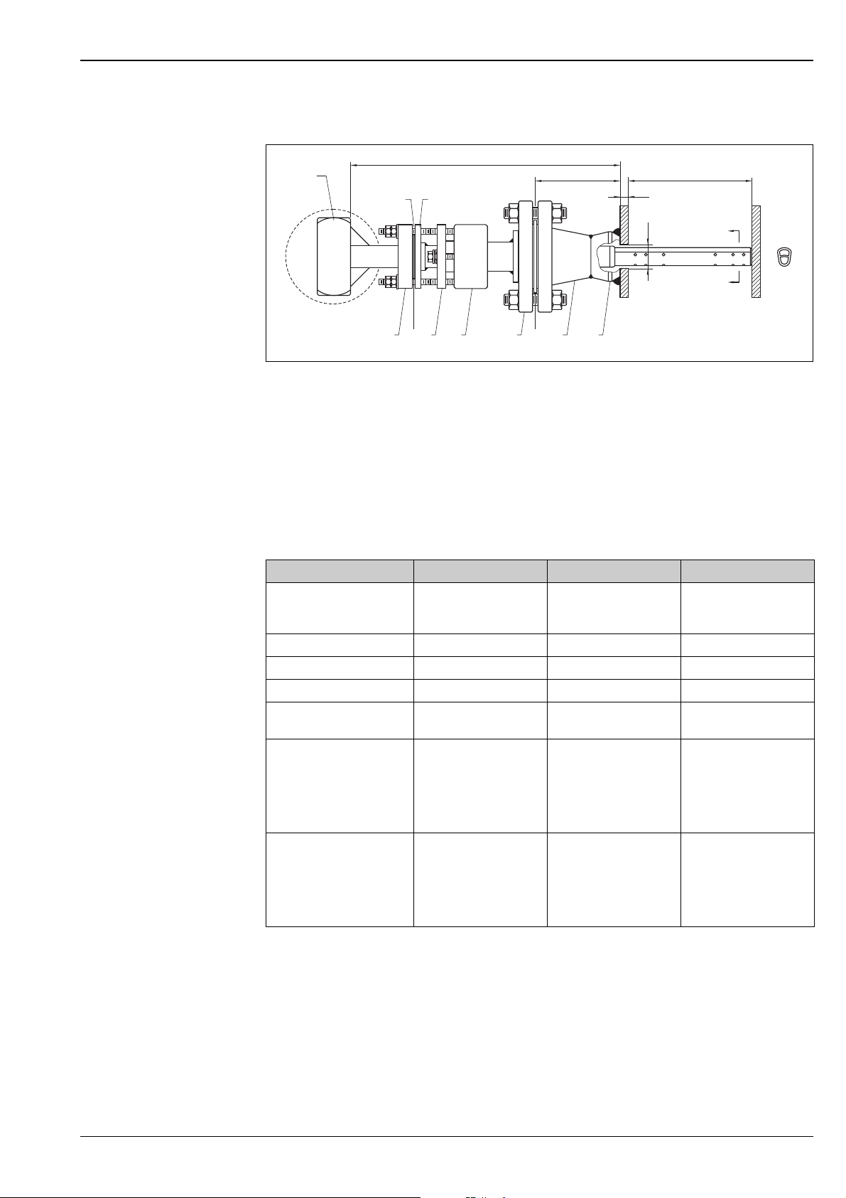
Deltatop DP71B, DP72B, DP73B
Process connection: "Spring lock + flange"
H
1
10
11
X
W
ID
D
2 3 4
1: Device head
2: Load plate
3: Load springs
4: Packing follower
5: Safety spring lock packing body
6: Sensor flange
7: Spiral-wound gasket
8: Weld neck flange
9: Welding socket
10: Visual load indication
11: Indication ring
ANSI class • Class 150
Sensor diameter 7/16" (11 mm) 7/8" (22 mm) 1-3/8" (35 mm)
Dim. "D" drilled hole diameter 1/2" (13 mm) 1" (25 mm) 1-1/2" (39 mm)
Flange and welding socket size 1" 1-1/2" 2"
Pipe size "ID" 2" - 6"
Dim. "X" • Class 300:
Dim. "H" • Class 300:
5 6
DP71B DP72B DP73B
• Class 300
• Class 600
(50 mm - 150 mm)
approx. 3.56" (90 mm)
• Class 600:
approx. 3.81" (97 mm)
approx. 12.0" (305 mm)
• Class 600:
approx. 12.5" (317 mm)
8 9
7
• Class 150
• Class 300
• Class 600
6" - 42"
(150 mm - 1050 mm)
• Class 150:
approx. 3.81" (97 mm)
• Class 300:
approx. 4.06" (103 mm)
• Class 600:
approx. 4.38" (111 mm)
• Class 150:
approx. 14.5" (368 mm)
• Class 300:
approx. 15.1" (383 mm)
• Class 600:
approx. 15.7" (399 mm)
A
A
P01-DP6xBxxx-06-00-00-xx-008
•Class 150
•Class 300
•Class 600
12" - 60"
(300 mm - 1500 mm)
• Class 150:
approx. 4.06" (103 mm)
• Class 300:
approx. 4.31" (110 mm)
• Class 600:
approx. 4.69" (119 mm)
• Class 150:
approx. 16.8" (427 mm)
• Class 300:
approx. 17.4" (441 mm)
• Class 600:
approx. 18.1" (460 mm)
A-A
!
Note!
The wall thickness "W" and the inner diameter "ID" of the pipe have to be specified when ordering a Deltatop
measuring system.
Endress+Hauser 19
Page 20
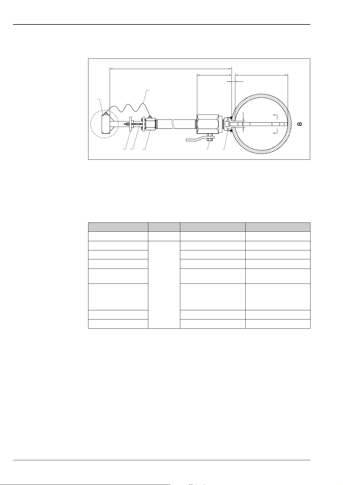
Process connection: "Flowtap + safety cable"
H
7
1
Deltatop DP71B, DP72B, DP73B
X
W
ID
D
4
3
2
Device head and access valve orientation shown 90 degrees from actual orientation for clarity.
1: Device head
2: Retaining ring
3: Studs and nuts
4: Packing glands
5: Access valve
6: Welding socket
7: Safety cable
DP71B DP72B DP73B
Max. pressure rating 30 psi (2.1 bar) 10 psi (0.7 bar)
Sensor diameter
Dim. "D" drilled hole diameter 1" (25 mm) 1-1/2" (39 mm)
Welding socket size 1-1/4" NPT 2" NPT
Pipe size "ID" 6" - 42"
Dim. "X" (valve) • For steel:
Dim. "H" - inserted H=ID+W+X+11.7" (279 mm) H=ID+W+X+13.5" (343 mm)
Dim. "H" - retracted H=2(ID+W+X)+11.5" (292 mm) H=2(ID+W+X)+13.2" (335 mm)
Not available
7/8" (22 mm) 1-3/8" (35 mm)
(150 mm - 1050 mm)
approx. 7.7" (196 mm)
• For 316SS
approx. 7.7" (196 mm)
6
5
12" - 60"
(300 mm - 1500 mm)
•For steel:
• For 316SS
A
A
P01-DP6xBxxx-06-00-00-xx-004
approx. 10.1" (257 mm)
approx. 8.8" (224 mm)
A-A
!
Note!
The wall thickness "W" and the inner diameter "ID" of the pipe have to be specified when ordering a Deltatop
measuring system.
20 Endress+Hauser
Page 21
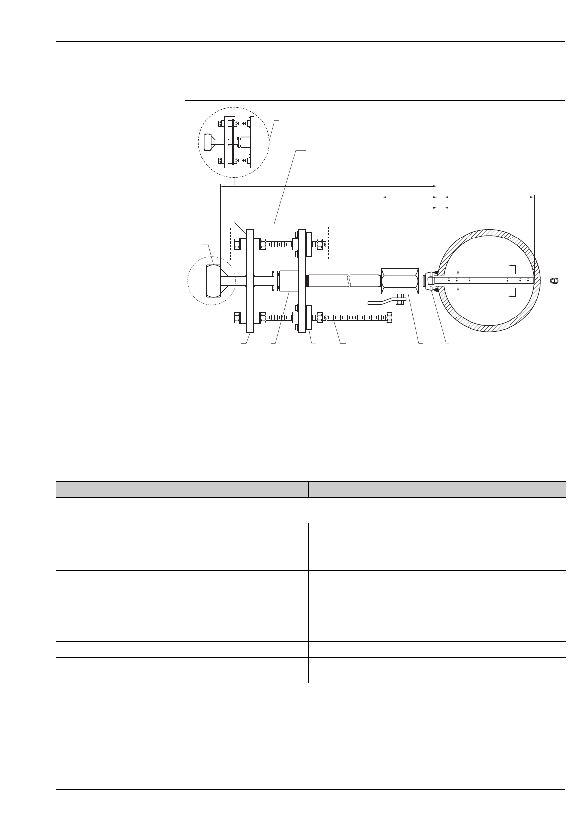
Deltatop DP71B, DP72B, DP73B
Process connection: "Flowtap" (single drive/double drive)
9
8
H
1
X
W
ID
D
6
3
2
Device head and access valve orientation shown 90 degrees from actual orientation for clarity.
1: Device head
2: Sensor plate
3: Packing gland
4: Anti-seize orbital bearing
5: Screw drive (threaded rod)
6: Access valve
7: Welding socket
8: Optional second drive rod (option for DP62B and DP63B)
9: Optional syncro drive
DP71B DP72B DP73B
Pressure rating 1000psi @ 100 °F (69 bar @ 38 °C)
Sensor diameter 7/16" (11 mm) 7/8" (22 mm) 1-3/8" (35 mm)
Dim. "D" drilled hole diameter 1/2" (13 mm) 1" (25 mm) 1-1/2" (39 mm)
Welding socket size 3/4" NPT 1-1/4" NPT 2" NPT
Pipe size "ID" 2" - 6"
Dim. "X" (valve) • For steel:
Dim. "H" - inserted H=ID+W+X+10.2" (260 mm) H=ID+W+X+11.6" (295 mm) H=ID+W+X+13.6" (345 mm)
Dim. "H" - retracted H=2(ID+W+X)+10.1" (257 mm) H=2(ID+W+X)+11.4" (290 mm)
(50 mm - 150 mm)
approx. 6.2" (157 mm)
• For 316SS:
approx. 6.0" (152 mm)
4
100psi @ 400 °F (6.9 bar @ 204 °C)
6" - 42"
(150 mm - 1050 mm)
• For steel:
• For 316SS:
add 1.5" for syncro drive
5
approx. 7.6" (193 mm)
approx. 7.7" (196 mm)
7
12" - 60"
(300 mm - 1500 mm)
•For steel:
approx. 9.1" (231 mm)
• For 316SS:
approx. 9.1" (231 mm)
H=2(ID+W+X)+13.3" (338 mm)
add 1.75" for syncro drive
A
A
P01-DP6xBxxx-06-00-00-xx-003
A-A
!
Note!
The wall thickness "W" and the inner diameter "ID" of the pipe have to be specified when ordering a Deltatop
measuring system.
Endress+Hauser 21
Page 22
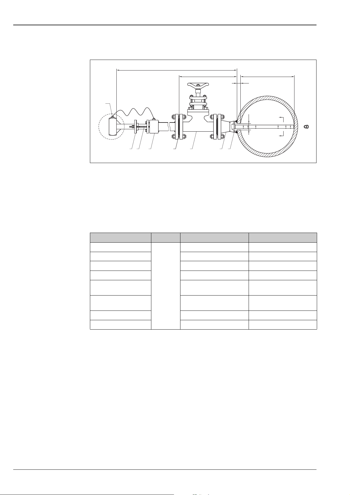
Process connection: "Flowtap + flange + safety cable"
H
X
1
Deltatop DP71B, DP72B, DP73B
ID
W
D
2 3 4 55 6 7 8
Device head and access valve orientation shown 90 degrees from actual orientation for clarity.
1: Device head
2: Retaining ring
3: Studs and nuts
4: Packing gland
5: Spiral wound gasket (2)
6: Flanged access valve
7: Weld neck flange
8: Welding socket
DP71B DP72B DP73B
Max. pressure rating
Sensor diameter 7/8" (22 mm) 1-3/8" (35 mm)
Dim. "D" drilled hole diameter 1" (25 mm) 1-1/2" (39 mm)
Flange size 1-1/2" NPT 2" NPT
Pipe size "ID" 6" - 42"
Dim. "X"
(flange face to outer pipe wall)
Dim. "H" - inserted H=ID+W+X+12.6" (320 mm) H=ID+W+X+14.4" (366 mm)
Dim. "H" - retracted H=2(ID+W+X)+13.2" (335 mm) H=2(ID+W+X)+15.0" (381 mm)
Not available
30 psi (2.1 bar) 10 psi (0.7 bar)
12" - 60"
(150 mm - 1050 mm)
10.5" (267 mm) 11.25" (286 mm)
(300 mm - 1500 mm)
A
A
P01-DP6xBxxx-06-00-00-xx-006
A-A
!
Note!
The wall thickness "W" and the inner diameter "ID" of the pipe have to be specified when ordering a Deltatop
measuring system.
22 Endress+Hauser
Page 23
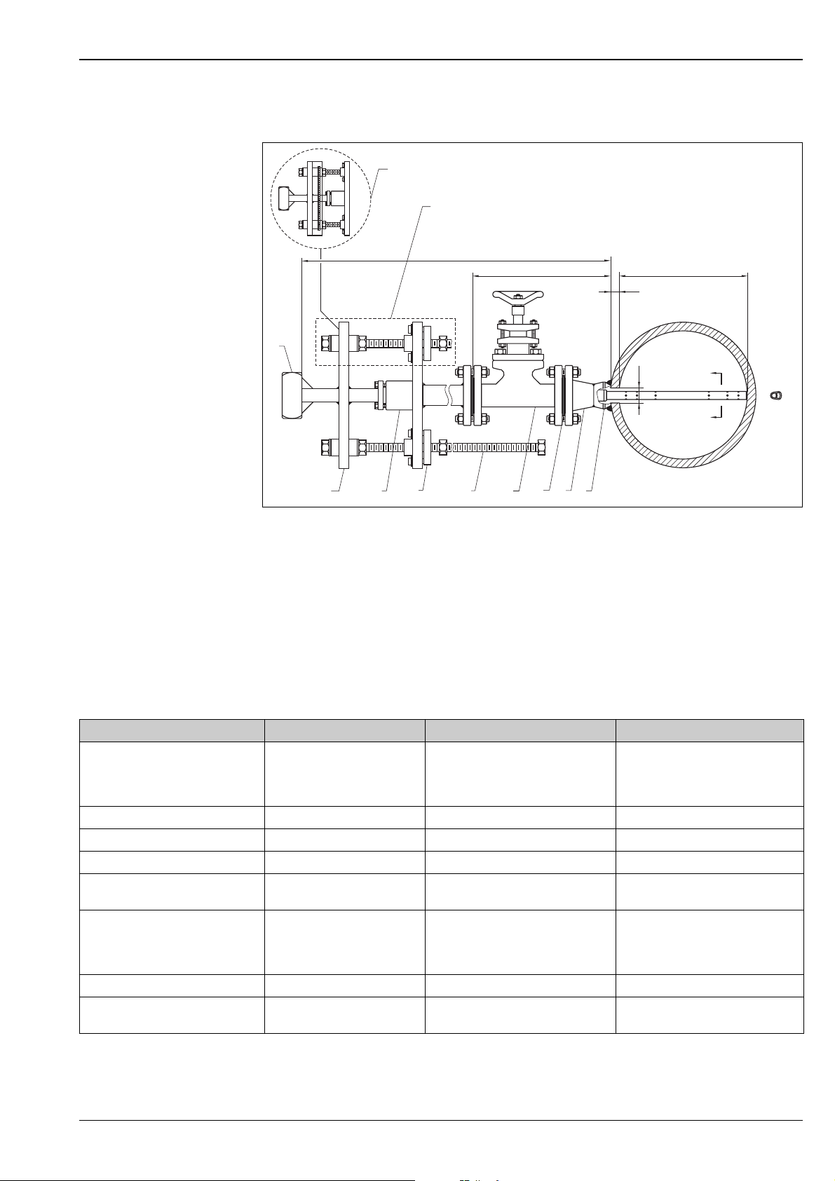
Deltatop DP71B, DP72B, DP73B
Process connection: "Flowtap + flange" (single drive/double drive)
11
10
H
X
1
ID
W
D
2
Device head and access valve orientation shown 90 degrees from actual orientation for clarity.
1: Device head
2: Sensor plate
3: Packing gland
4: Anti-seize orbital bearing
5: Drive rod
6: Flanged access valve
7: Spiral wound gasket (2)
8: Weld neck flange
9: Welding socket
10: Optional second drive rod (option for DP72B and DP73B)
11: Optional syncro drive
DP71B DP72B DP73B
Pressure rating • Single spindle:
Sensor diameter 7/16" (11 mm) 7/8" (22 mm) 1-3/8" (35 mm)
Dim. "D" drilled hole diameter 1/2" (13 mm) 1" (25 mm) 1-1/2" (39 mm)
Flange size 1/2" 1" 1-1/2"
Pipe size "ID" 2" - 6"
Dim. "X"
(flange face to outer pipe wall)
Dim. "H" - inserted H=ID+W+X+11.0" (279 mm) H=ID+W+X+12.5" (318 mm) H=ID+W+X+14.5" (368 mm)
Dim. "H" - retracted H=2(ID+W+X)+11.6" (294 mm) H=2(ID+W+X)+13.1" (333 mm)
ANSI Class 600
(50 mm - 150 mm)
12.5" (318 mm) • ANSI Class 150:
4
3
• Single spindle:
ANSI Class 150
• Double spindle:
ANSI Class 600
6" - 42"
(150 mm - 1050 mm)
approx. 10.5" (267 mm)
• ANSI Class 600:
approx. 14.06" (357 mm)
add 1.5" for syncro drive
6
5
8
7
9
• Single spindle:
ANSI Class 150
• Double spindle:
ANSI Class 600
12" - 60"
(300 mm - 1500 mm)
• ANSI Class 150:
approx. 10.25" (286 mm)
• ANSI Class 600:
approx. 16.38" (416 mm)
H=2(ID+W+X)+15.1" (384 mm)
add 1.75" for syncro drive
A
A
P01-DP6xBxxx-06-00-00-xx-005
A-A
!
Note!
The wall thickness "W" and the inner diameter "ID" of the pipe have to be specified when ordering a Deltatop
measuring system.
Endress+Hauser 23
Page 24
Deltatop DP71B, DP72B, DP73B
Process connection, mounting nozzle
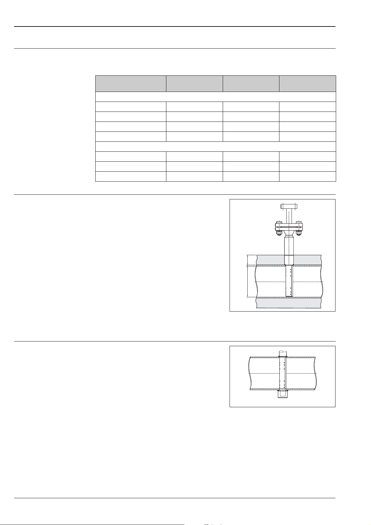
Extension welding socket
The features 40 ("Process connection") and 70 ("Welding socket") of the product structure must always be
selected in a suitable combination:
Process connection, mounting
nozzle
Standard versions
Welding socket 300# to 600# A** A**
Spring lock 600# A** A**
Flange connection 150# to 2500# G** G**
Flange connection and spring lock 150# to 600# P** P**
Flowtap version for exchanging the Pitot tube during ongoing operation
Flowtap with safety chain 10psi to 30psi R** R**
Flowtap with spindle 150# to 600# R** R**
Flowtap with flange and spindle 150# to 600# R** R**
Pressure rating Feature 40
"Process connection"
Feature 70
"Welding socket"
With insulated pipes, the length of the welding socket
must be increased by the thickness H of the insulating
layer. Therefore, this thickness must be specified on
the "Sizing sheet - data sheet" (→ ä 49). The
material of the mounting nozzle extension must be
specified in the product structure (feature 80).
The following lengths are available for the extension
of the mounting nozzle:
•2" (50 mm)
•4" (100 mm)
H
•5" (127 mm)
• 6" (152.4 mm)
ID
End support
P01-DPBxxxxx-14-xx-xx-xx-003
ID: Inner pipe diameter;
H: Thickness of the insulating layer
For Pitot tubes, an end support can optionally be
applied (e.g. for large flow velocities).
The probe length to be specified is always the inner
pipe diameter plus one time the wall thickness. The
additional length required for the end support is taken
into account by Endress+Hauser
P01-DPBxxxxx-14-xx-xx-xx-004
24 Endress+Hauser
Page 25
Deltatop DP71B, DP72B, DP73B
Differential pressure connection
!
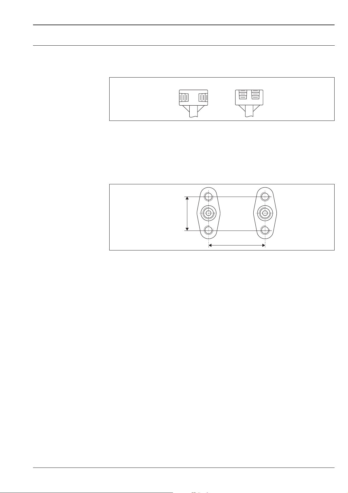
Differential pressure connection for the remote version (FNPT 1/2")
For the remote version, the following connections are available for the impulse line between the individual
components (remark: simple mounting; not suited for steam):
12
P01-DP6xBxxx-04-00-00-xx-001
1: FNPT 1/2"
2: FNPT 1/2", parallel
Note!
The differential pressure connection is selected in feature 100 of the product structure.
Differential pressure connection for the compact version (IEC61518)
1,3)
1.6 (4
!
inch (mm)
Standard connection for differential pressure transmitter (oval flanges or flange plate); dimensions in mm (inch)
Note!
The differential pressure connection is selected in feature 100 of the product structure.
2.1 (54)
P01-DOxxxxx-15-xx-xx-xx-014
Endress+Hauser 25
Page 26
Integrated temperature sensor
Deltatop DP71B, DP72B, DP73B
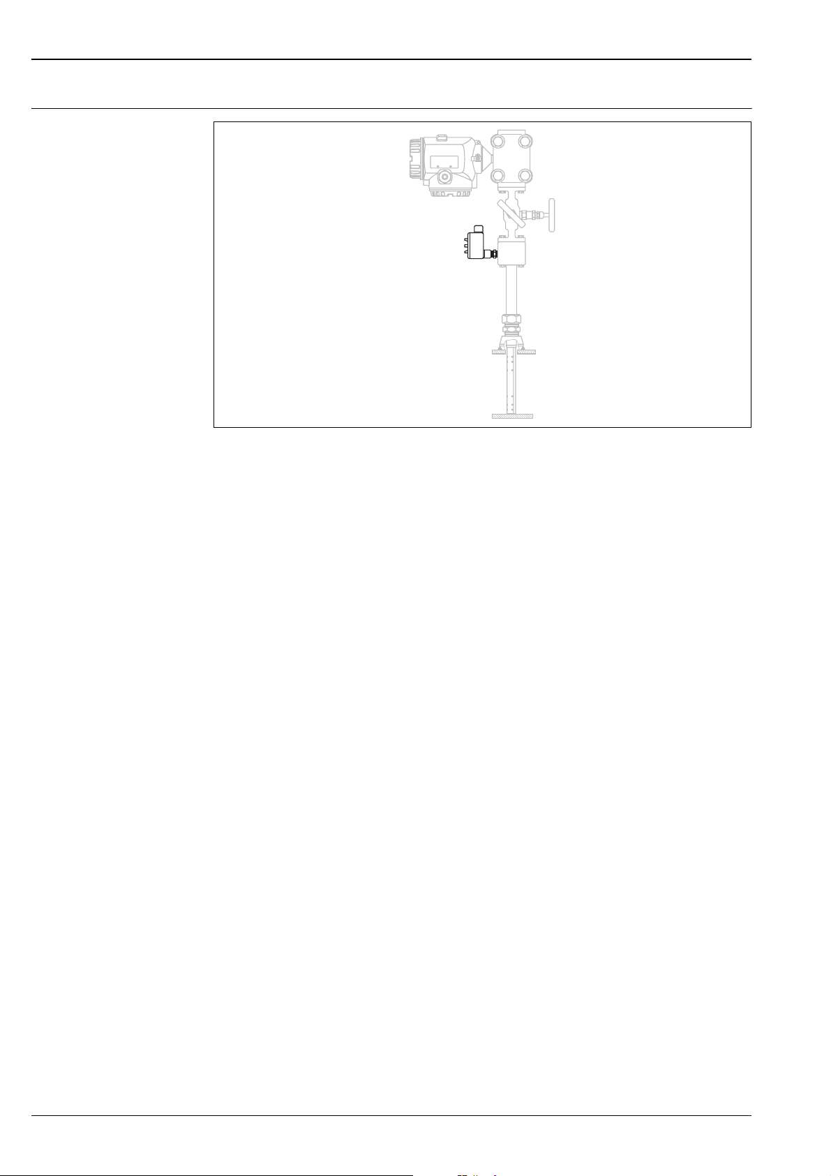
P01-DOxxxxx-15-xx-xx-xx-009
!
• For Pitot tubes:
– DP72B
– DP73B
• The resistance thermometer Pt100 is fixed within the probe profile. The protective tube which is formed by
the two partition walls between the probe chambers protects it against damage. It is not in contact with the
medium.
• Material of the sensor: 1.4571 (SS316TI)
Robust and resistant to vibrations
• Rapid installation and removal possible under operating pressure
• Measuring range: -328 °F to +1112 °F
( -200 °C to +600 °C)
• Probe head made of aluminum
• Output signal:
– Pt100, 3-wire connection
Note!
The integrated temperature sensor can be applied for pressure ratings up to Class 300/PN40.
26 Endress+Hauser
Page 27

Deltatop DP71B, DP72B, DP73B
Overview of the product structures
Feature Name Description Valid for
DP71B
Primary element
10 Application; Version • Application: "Gas", "Liquid" or "Steam"
• Version: "remote" or "compact"
See chapter "Mounting positions" (→ ä 10).
20 Pipe; Orientation • Pipe: "Horizontal", "Vertical"
• Orientation:
– "left", "right", "top/bottom" for horizontal pipes
– "upwards", "downwards", "upwards/downwards" for vertical pipes
See chapter "Mounting positions" (→ ä 10).
40 Process connection Defines the size, type and material of the process connection:
• Pipe > cutting ring (→ ä 16)
• Pipe > spring lock (→ ä 17)
• Flowtap (single drive / double drive) (→ ä 21)
• Flowtap + safety cable (→ ä 20)
• Flowtap + flange (single drive / double drive) (→ ä 23)
• Flowtap + flange + safety cable (→ ä 22)
• ANSI flange (→ ä 18)
• Spring lock + flange (→ ä 19)
For the temperature limits of the materials → ä 13.
60 Probe length Defines the length of the probe in mm. The probe length is the sum of the inner pipe
70 Welding socket Defines the type, size, pressure rating and material of the mounting nozzle.
80 Extension welding socket Defines the length and material of the mounting nozzle extension.
90 End support Defines the material of the end support (→ ä 24).
100 Diff pressure connection; Seal Defines:
110 Temperature sensor Pt100 Selection of the temperature sensor if needed.
diameter plus the wall thickness of the pipe.
The selection must match the selected process connection (feature 40).
For the temperature limits of the materials → ä 13.
The extension of the mounting nozzle is required for insulated pipes (→ ä 24).
Possible lengths: 1.97" (50 mm), 3.94" (100 mm), 4.33" (110 mm), 4.72" (120 mm),
5.12" (130 mm), etc.
Note!
!
The selected material must match the selection in feature 70 "Welding socket".
Note!
!
"Not selected" means that no mounting nozzle extension is required 0" (= 0 mm).
Note!
!
"Not selected" means that the order does not contain an end support.
• The type of differential pressure connection (→ ä 25)
• The material of the seal at the differential pressure connection
For details → ä 26.
Note!
!
"Not selected" means that no temperature sensor is integrated.
xxx
xxx
xxx
xxx
xxx
xxx
xxx
xxx
xx
DP72B
DP73B
Endress+Hauser 27
Page 28

Deltatop DP71B, DP72B, DP73B
Feature Name Description valid for
DP71B
DP72B
DP73B
Accessory: Condensate chamber on request
200 2x condens. chamber mat.;
volume; PN
210 Filling cap condens. chamber Defines the type of filling cap. x x x
220 Inlet condens. chamber Defines the inlet (from the process) of the condensate chamber. x x x
230 Outlet condens. chamber Defines the outlet of the condensate chamber. x x x
Accessory: Shut-off valve
250 2 x shut-off valve Defines:
260 Material shut-off valve Defines the material of the shut-off valve.
270 Inlet shut-off valve Defines the inlet (from the process) of the shut-off valve. x x x
280 Outlet shut-off valve Defines the outlet of the shut-off valve. x x x
Accessory: Manifold
300 Manifold version Defines the manifold version (→ ä 42).
310 Gasket manifold Defines the material of the gasket of the manifold.
320 Process connection manifold Defines the process connection of the manifold. x x x
330 Seal manifold, screws Defines:
Differential pressure transmitter
450 DP transmitter Deltabar Defines if a Deltabar differential pressure transmitter is provided separately. x x x
Additional options
500 Add. option Pitot tube These features are used to define additional characteristics of the respective
510 Add. option temperature sensor xx
520 Add. option condensate chamber xxx
530 Add. option shut-off valve xxx
540 Add. option manifold xxx
550 Add. option general xxx
895 Marking Selection of customer-specific device labeling. x x x
Defines:
• The material of the condensate chambers
• The volume of the condensate chambers
• The pressure rating of the condensate chambers
Note!
!
If "not selected" is chosen, no condensate chambers are included in the order. In this
case "not needed" has to be selected in features 210 to 230.
• The type of shut-off valve
• The material of the gasket
For details → ä 41.
Note!
!
If "not selected" is chosen, no shut-off valves are included in the order. In this case "not
needed" has to be selected in features 260 to 280.
For the temperature limits of the materials → ä 13.
Note!
!
If "not selected" is chosen, no manifold is included in the order. In this case "not
needed" has to be selected in features 310 to 330.
For the temperature limits of the materials → ä 13.
• The material of the seal between the manifold and the transmitter
• The size of the manifold screws
For the temperature limits of the materials → ä 13.
Caution!
"
The manifold screws must be selected in accordance with the Deltabar differential
pressure transmitter.
components (e.g. material inspection certificates).
The features are optional, which means:
• It is not necessary to select an option in these features.
• Multiple options can be selected in these features.
xxx
xxx
xxx
xxx
xxx
xxx
xxx
28 Endress+Hauser
Page 29

Deltatop DP71B, DP72B, DP73B
Ordering information
Product structure Deltatop DP71B
10 Application; Version
BGas; remote
DLiquid; remote
F Steam; remote
Y Special version, to be specified
20 Pipe; Orientation
D Horizontal; top/bottom
W Vertical; upwards/downwards
Y Special version, to be specified
40 Process connection
Tube
AGC Tube > cutting ring, Cl. 600, 316
ALC Tube > spring lock, Cl. 600, 316
ANSI flanges
GAC 1" Cl.150 RF, 316
GBC 1" Cl.300 RF, 316
GCC 1" Cl.600 RF, 316
GEC 1" Cl.1500 RF, 316
GFC 1" Cl.2500 RF, 316
Spring lock
PGC 1" Cl. 150 RF, 316, spring lock
PHC 1" Cl.300 RF, 316, spring lock
PIC 1" Cl.600 RF, 316, spring lock
Flowtap
RCC Flowtap Cl.600, 316 + single spindle
ROC Flowtap Cl.600, 316 + flange + single spindle
Y99 Special version, to be specified
60 Probe length (pipe ID + wall thickness)
A4 ... mm 316
J4 ... mm 316, flowtap Cl.600
R4 ... inch 316
V4 ... inch 316, flowtap Cl.600
Y9 Special version, to be specified
70 Welding socket
Cutting ring
AQA Cutting ring, Cl.600, steel
AQC Cutting ring, Cl.600, 316
ANSI flanges
GAA 1" Cl.150 RF, steel
GAC 1" Cl.150 RF, 316
GBA 1" Cl.300 RF, steel
GBC 1" Cl.300 RF, 316
GCA 1" Cl.600 RF, steel
GCC 1" Cl.600 RF, 316
GEA 1" Cl.1500 RF, steel
GEC 1" Cl.1500 RF, 316
GFA 1" Cl.2500 RF, steel
GFC 1" Cl.2500 RF, 316
Spring lock
PCA Cl.600, steel, spring lock
PCC Cl.600, 316, spring lock
Flowtap
RCA Flowtap Cl.600, steel + single spindle
RCC Flowtap Cl.600, 316 + single spindle
ROA Flowtap Cl.600, steel + flange + single spindle
ROC Flowtap Cl.600, 316 + flange + single spindle
Miscellaneous
XAX Not selected
Y99 Special version, to be specified
80 Extension welding socket
A ... mm, carbon steel
D ... mm, 316
K ... inch, carbon steel
Endress+Hauser 29
Page 30
80 Extension welding socket
L ... inch, 316
1 Not selected
9 Special version, to be specified
90 End support
A Carbon steel
D316
S Carbon steel, high pressure > Cl.600
T 316, high pressure > Cl.600
1 Not selected
2 Prepared for end support
9 Special version, to be specified
100 Diff. pressure connection; Seal
1FNPT1/2; w/o
2 FNPT1/2; w/o, parallel
Y Special version, to be specified
200 2x condens. chamber mat.; Volume; PN
1 Not selected
9 Special version, to be specified
210 Filling cap condens. chamber
A Not needed
Y Special version, to be specified
220 Inlet condens. chamber
A Not needed
Y Special version, to be specified
230 Outlet condens. chamber
A Not needed
Y Special version, to be specified
250 2x shut-off valve
1 Not selected
6 Valve; PTFE gasket, 392°F (200°C)
8 Valve; pure graphite gasket, 572°F (300°C)
9 Special version, to be specified
260 Material shut-off valve
A Not needed
E316
Y Special version, to be specified
270 Inlet shut-off valve
A Not needed
DFNPT1/2
UIntegral
Y Special version, to be specified
280 Outlet shut-off valve
A Not needed
CFNPT1/2
Y Special version, to be specified
300 Manifold version
111 Not selected
AB2 3 valve, 316L, milled
BB2 5 valve, 316L, milled, vent
YY9 Special version, to be specified
310 Gasket manifold
A Not needed
B PTFE, 200 °C
D Graphite / Graphoil
Y Special version, to be specified
320 Process connection manifold
A Not needed
BFNPT1/2
Y Special version, to be specified
Deltatop DP71B, DP72B, DP73B
30 Endress+Hauser
Page 31

Deltatop DP71B, DP72B, DP73B
330 Seal manifold; Screws
A Not needed
B PTFE; UNF7/16, max 420 bar
D Viton; UNF7/16, max 420 bar
K Graphite; UNF7/16, max 420 bar
Y Special version, to be specified
450 DP transmitter Deltabar
D Provided, sep. item
W Not provided
500 Add. option Pitot tube
(optional; multiple options can be selected)
A1 EN10204-3.1 material (wetted parts) inspection certificate
A2 EN10204-3.1 material, NACE MR0175 (wetted parts) inspection certificate
A5 Cleaned from oil+grease
A6 Oxygen service
520 Add. option condensate chamber
(optional; multiple options can be selected)
C1 EN10204-3.1 material (wetted parts) inspection certificate
C2 EN10204-3.1 material, NACE MR0175 (wetted parts) inspection certificate
530 Add. option shut-off valve
(optional; multiple options can be selected)
D1 EN10204-3.1 material (wetted parts) inspection certificate
D2 EN10204-3.1 material, NACE MR0175 (wetted parts) inspection certificate
D5 Cleaned from oil+grease
D6 Oxygen service
540 Add. option manifold
(optional; multiple options can be selected)
E1 EN10204-3.1 material (wetted parts) inspection certificate
E2 EN10204-3.1 material, NACE MR0175 (wetted parts) inspection certificate
E5 Cleaned from oil+grease
E6 Oxygen service
550 Add. option general
(optional; multiple options can be selected)
F8 Pressure test + certificate
895 Marking
Z1 Tagging (TAG), see additional spec.
Endress+Hauser 31
Page 32

Deltatop DP71B, DP72B, DP73B
Product structure Deltatop DP72B
10 Application; Version
BGas; remote
C Gas; compact
DLiquid; remote
E Liquid; compact
F Steam; remote
G Steam; compact
Y Special version, to be specified
20 Pipe; Orientation
B Horizontal; left
C Horizontal; right
D Horizontal; top/bottom
U Vertical; downwards
VVertical; upwards
W Vertical; upwards/downwards
Y Special version, to be specified
40 Process connection
Tube
AFC Tube > cutting ring, Cl.300, 316
ALC Tube > spring lock, Cl.600, 316
ANSI flanges
GNC 1-1/2" Cl.150 RF, 316
GPC 1-1/2" Cl.300 RF, 316
GQC 1-1/2" Cl.600 RF, 316
GSC 1-1/2" Cl.1500 RF, 316
GTC 1-1/2" Cl.2500 RF, 316
Spring lock
PMC 1-1/2" Cl.150 RF, 316, spring lock
PNC 1-1/2" Cl.300 RF, 316, spring lock
POC 1-1/2" Cl.600 RF, 316, spring lock
Flowtap
RAC Flowtap Cl.150, 316 + single spindle
RIC Flowtap Cl.600, 316 + double spindle
RMC Flowtap Cl.150, 316 + flange + single spindle
RUC Flowtap Cl.600, 316 + flange + double spindle
ROC Flowtap 30psi, 316 + safety cable
R2C Flowtap 30psi, 316 + flange + safety cable
Y99 Special version, to be specified
60 Probe length (pipe ID + wall thickness)
A4 ... mm 316
L4 ... mm 316, flowtap 30psi
M4 ... mm 316, flowtap Cl.150
N4 ... mm 316, flowtap Cl.600
R4 ... inch 316
S4 ... inch 316, flowtap 30psi
T4 ... inch 316, flowtap Cl.150
V4 ... inch 316, flowtap Cl.600
Y9 Special version, to be specified
70 Welding socket
Cutting ring
APA Cutting ring, Cl.300, steel
APC Cutting ring, Cl.300, 316
ANSI flanges
GNA 1-1/2" Cl.150 RF, steel
GNC 1-1/2" Cl.150 RF, 316
GPA 1-1/2" Cl.300 RF, steel
GPC 1-1/2" Cl.300 RF, 316
GQA 1-1/2" Cl.600 RF, steel
GQC 1-1/2" Cl.600 RF, 316
GSA 1-1/2" Cl.1500 RF, steel
GSC 1-1/2" Cl.1500 RF, 316
GTA 1-1/2" Cl.2500 RF, steel
GTC 1-1/2" Cl.2500 RF, 316
Spring lock
PCA Cl.600, steel, spring lock
PCC Cl.600, 316, spring lock
32 Endress+Hauser
Page 33
Deltatop DP71B, DP72B, DP73B
70 Welding socket
Flowtap
RAA Flowtap Cl.150, steel + single spindle
RAC Flowtap Cl.150, 316 + single spindle
RIA Flowtap Cl.600, steel + double spindle
RIC Flowtap Cl.600, 316 + double spindle
RMA Flowtap Cl.150, steel + flange + single spindle
RMC Flowtap Cl.150, 316 + flange + single spindle
RUA Flowtap Cl.600, steel + flange + double spindle
RUC Flowtap Cl.600, 316 + flange + double spindle
R0A Flowtap 30psi, steel + safety cable
R0C Flowtap 30psi, 316 + safety cable
R2A Flowtap 30psi, steel + flange + safety cable
R2C Flowtap 30psi, 316 + flange + safety cable
Miscellaneous
XAX Not selected
Y99 Special version, to be specified
80 Extension welding socket
A ... mm, carbon steel
D ... mm, 316
K ... inch, carbon steel
L ... inch, 316
1Not selected
9 Special version, to be specified
90 End support
A Carbon steel
D316
S Carbon steel, high pressure > Cl.600
T 316, high pressure > Cl.600
1Not selected
2 Prepared for end support
9 Special version, to be specified
100 Diff. pressure connection; Seal
B IEC61518; PTFE
C IEC61518; FKM
F IEC61518; graphite
1FNPT1/2; w/o
2 FNPT1/2; w/o, parallel
Y Special version, to be specified
110 Temperature sensor Pt100
A Not selected
F Terminal block 3-wire, max 425°C
Y Special version, to be specified
200 2x condens. chamber mat.; Volume; Pn
1Not selected
9 Special version, to be specified
210 Filling cap condens. chamber
A Not needed
Y Special version, to be specified
220 Inlet condens. chamber
A Not needed
Y Special version, to be specified
230 Outlet condens. chamber
A Not needed
Y Special version, to be specified
250 2x shut-off valve
1 Not selected
6 Valve; PTFE gasket, 392°F (200°C)
8 Valve; pure graphite gasket, 572°F (300°C)
9 Special version, to be specified
260 Material shut-off valve
A Not needed
E316
Endress+Hauser 33
Page 34
260 Material shut-off valve
Y Special version, to be specified
270 Inlet shut-off valve
A Not needed
DFNPT 1/2
UIntegral
Y Special version, to be specified
280 Outlet shut-off valve
A Not needed
CFNPT1/2
Y Special version, to be specified
300 Manifold version
111 Not selected
AB2 3 valve, 316L, milled
BB2 5 valve, 316L, milled, vent
HA2 3 valve, 316L, integral, IEC61518
KA2 3 valve, 316L, forging, IEC61518, both sides
LA2 5 valve, 316L, forging, IEC61518, both sides, vent
YY9 Special version, to be specified
310 Gasket manifold
A Not needed
B PTFE, 200 °C
D Graphite / Graphoil
Y Special version, to be specified
320 Process connection manifold
A Not needed
BFNPT1/2
E IEC61518
Y Special version, to be specified
330 Seal manifold; Screws
A Not needed
B PTFE; UNF7/16, max 420bar
D Viton; UNF7/16, max 420bar
K Graphite; UNF7/16, max 420bar
Y Special version, to be specified
450 DP transmitter Deltabar
D Provided, sep. item
W Not provided
500 Add. option Pitot tube
(optional; multiple options can be selected)
AA Syncro drive, flowtap + double spindle
A1 EN10204-3.1 material (wetted parts) inspection certificate
A2 EN10204-3.1 material, NACE MR0175 (wetted parts) inspection certificate
A5 Cleaned from oil+grease
A6 Oxygen service
510 Additional option temperature sensor
(optional; multiple options can be selected)
B7 Explosion protection NEMA6
520 Add. option condensate chamber
(optional; multiple options can be selected)
C1 EN10204-3.1 material (wetted parts) inspection certificate
C2 EN10204-3.1 material, NACE MR0175 (wetted parts) inspection certificate
530 Add. option shut-off valve
(optional; multiple options can be selected)
D1 EN10204-3.1 material (wetted parts) inspection certificate
D2 EN10204-3.1 material, NACE MR0175 (wetted parts) inspection certificate
D5 Cleaned from oil+grease
D6 Oxygen service
540 Add. option manifold
(optional; multiple options can be selected)
E1 EN10204-3.1 material (wetted parts) inspection certificate
E2 EN10204-3.1 material, NACE MR0175 (wetted parts) inspection certificate
Deltatop DP71B, DP72B, DP73B
34 Endress+Hauser
Page 35

Deltatop DP71B, DP72B, DP73B
540 Add. option manifold
(optional; multiple options can be selected)
E5 Cleaned from oil+grease
E6 Oxygen service
550 Add. option general
(optional; multiple options can be selected)
F8 Pressure test + certificate
895 Marking
Z1 Tagging (TAG), see additional spec.
Endress+Hauser 35
Page 36

Deltatop DP71B, DP72B, DP73B
Product structure Deltatop DP73B
10 Application; Version
BGas; remote
C Gas; compact
DLiquid; remote
E Liquid; compact
F Steam; remote
G Steam; compact
Y Special version, to be specified
20 Pipe; Orientation
B Horizontal; left
C Horizontal; right
D Horizontal; top/bottom
U Vertical; downwards
VVertical; upwards
W Vertical; upwards/downwards
Y Special version, to be specified
40 Process connection
Tube
ALC Tube > spring lock, Cl.600, 316
ANSI flanges
HAC 2" Cl.150 RF, 316
HBC 2" Cl.300 RF, 316
HCC 2" Cl.600 RF, 316
HEC 3" Cl.1500 RF, 316
HFC 3" Cl.2500 RF, 316
Spring lock
PSC 2" Cl.150 RF, 316, spring lock
PTC 2" Cl.300 RF, 316, spring lock
PUC 2" Cl.600 RF, 316, spring lock
Flowtap
RAC Flowtap Cl.150, 316 + single spindle
RIC Flowtap Cl.600, 316 + double spindle
RMC Flowtap Cl.150, 316 + flange + single spindle
RUC Flowtap Cl.600, 316 + flange + double spindle
R0C Flowtap 10psi, 316 + safety cable
R2C Flowtap 10psi, 316 + flange + safety cable
Miscellaneous
Y99 Special version, to be specified
60 Probe length (pipe ID + wall thickness)
A4 ... mm 316
K4 ... mm 316, from 1601mm
L4 ... mm 316, flowtap 10psi
M4 ... mm 316, flowtap Cl.150
N4 ... mm 316, flowtap Cl.600
S4 ... inch 316, flowtap 10psi
T4 ... inch 316, flowtap Cl.150
U4 ... inch 316, to 60inch
V4 ... inch 316, flowtap Cl.600
W4 ... inch 316, from 61inch
Y9 Special version, to be specified
70 Welding socket
ANSI flanges
HAA 2" Cl.150 RF, steel
HAC 2" Cl.150 RF, 316
HBA 2" Cl.300 RF, steel
HBC 2" Cl.300 RF, 316
HCA 2" Cl.600 RF, steel
HCC 2" Cl.600 RF, 316
HEA 3" Cl.1500 RF, steel
HEC 3" Cl.1500 RF, 316
HFA 3" Cl.2500 RF, steel
HFC 3" Cl.2500 RF, 316
Spring lock
PCA Cl.600, steel, spring lock
PCC Cl.600, 316, spring lock
36 Endress+Hauser
Page 37
Deltatop DP71B, DP72B, DP73B
70 Welding socket
Flowtap
RAA Flowtap Cl.150, steel + single spindle
RAC Flowtap Cl.150, 316 + single spindle
RIA Flowtap Cl.600, steel + double spindle
RIC Flowtap Cl.600, 316 + double spindle
RMA Flowtap Cl.150, steel + flange + single spindle
RMC Flowtap Cl.150, 316 +flange + single spindle
RUA Flowtap Cl.600, steel + flange + double spindle
RUC Flowtap Cl.600, 316 + flange + double spindle
R0A Flowtap 10psi, steel + safety cable
R0C Flowtap 10psi, 316 + safety cable
R2A Flowtap 10psi, steel + flange + safety cable
R2C Flowtap 10psi, 316 + flange + safety cable
Miscellaneous
XAX Not selected
Y99 Special version, to be specified
80 Extension welding socket
A ... mm, carbon steel
D ... mm, 316
K ... inch, carbon steel
L ... inch, 316
1Not selected
9 Special version, to be specified
90 End support
A Carbon steel
D316
S Carbon steel, high pressure > Cl.600
T 316, high pressure > Cl.600
1Not selected
2 Prepared for end support
9 Special version, to be specified
100 Diff. pressure connection; Seal
B IEC61518; PTFE
C IEC61518; FKM
F IEC61518; graphite
1FNPT1/2; w/o
2 FNPT1/2; w/o, parallel
Y Special version, to be specified
110 Temperature sensor Pt100
A Not selected
F Terminal block 3-wire, max 425°C
Y Special version, to be specified
200 2x condens. chamber mat.; Volume; Pn
1Not selected
9 Special version, to be specified
210 Filling cap condens. chamber
A Not needed
Y Special version, to be specified
220 Inlet condens. chamber
A Not needed
Y Special version, to be specified
230 Outlet condens. chamber
A Not needed
Y Special version, to be specified
250 2x shut-off valve
1 Not selected
6 Valve; PTFE gasket, 392°F (200°C)
8 Valve; pure graphite gasket, 572°F (300°C)
9 Special version, to be specified
260 Material shut-off valve
A Not needed
E316
Endress+Hauser 37
Page 38
260 Material shut-off valve
Y Special version, to be specified
270 Inlet shut-off valve
A Not needed
DFNPT1/2
UIntegral
Y Special version, to be specified
280 Outlet shut-off valve
A Not needed
CFNPT1/2
Y Special version, to be specified
300 Manifold version
111 Not selected
AB2 3 valve, 316L, milled
BB2 5 valve, 316L, milled, vent
HA2 3 valve, 316L, integral, IEC61518
KA2 3 valve, 316, forging, IEC61518, both sides
LA2 5 valve, 316, forging, IEC61518 both sides, vent
YY9 Special version, to be specified
310 Gasket manifold
A Not needed
B PTFE, 200 °C
D Graphite / Graphoil
Y Special version, to be specified
320 Process connection manifold
A Not needed
BFNPT1/2
E IEC61518
Y Special version, to be specified
330 Seal manifold; Screws
A Not needed
B PTFE; UNF7/16, max 420bar
D Viton; UNF7/16, max 420bar
K Graphite; UNF7/16, max 420bar
Y Special version, to be specified
450 DP transmitter Deltabar
D Provided, sep. item
W Not provided
500 Add. option Pitot tube
(optional; multiple options can be selected)
AA Syncro drive, flowtap + double spindle
A1 EN10204-3.1 material (wetted parts) inspection certificate
A2 EN10204-3.1 material, NACE MR0175 (wetted parts) inspection certificate
A5 Cleaned from oil+grease
A6 Oxygen service
510 Add. option temperature sensor
(optional; multiple options can be selected)
B7 Explosion protection NEMA6
520 Add. option condensate chamber
(optional; multiple options can be selected)
C1 EN10204-3.1 material (wetted parts) inspection certificate
C2 EN10204-3.1 material, NACE MR0175 (wetted parts) inspection certificate
530 Add. option shut-off valve
(optional; multiple options can be selected)
D1 EN10204-3.1 material (wetted parts) inspection certificate
D2 EN10204-3.1 material, NACE MR0175 (wetted parts) inspection certificate
D5 Cleaned from oil+grease
D6 Oxygen service
540 Add. option manifold
(optional; multiple options can be selected)
E1 EN10204-3.1 material (wetted parts) inspection certificate
E2 EN10204-3.1 material, NACE MR0175 (wetted parts) inspection certificate
Deltatop DP71B, DP72B, DP73B
38 Endress+Hauser
Page 39

Deltatop DP71B, DP72B, DP73B
540 Add. option manifold
(optional; multiple options can be selected)
E5 Cleaned from oil+grease
E6 Oxygen service
550 Add. option general
(optional; multiple options can be selected)
F8 Pressure test + certificate
895 Marking
Z1 Tagging (TAG), see additional spec.
Endress+Hauser 39
Page 40

Deltatop DP71B, DP72B, DP73B
Accessories
Overview The following accessories are available for differential-pressure flow measurement with Pitot tubes:
• DA73V: Shut-off valves (→ ä 41)
• DA74M: Manifold (→ ä 42)
Shut-off valves and the manifold can be ordered together with the Pitot tube. They are contained in the product
structures DP71B, DP72B and DP73B.
Alternatively, they can be ordered via their own product structures. The product structures are listed in the
following chapters.
40 Endress+Hauser
Page 41
Deltatop DP71B, DP72B, DP73B
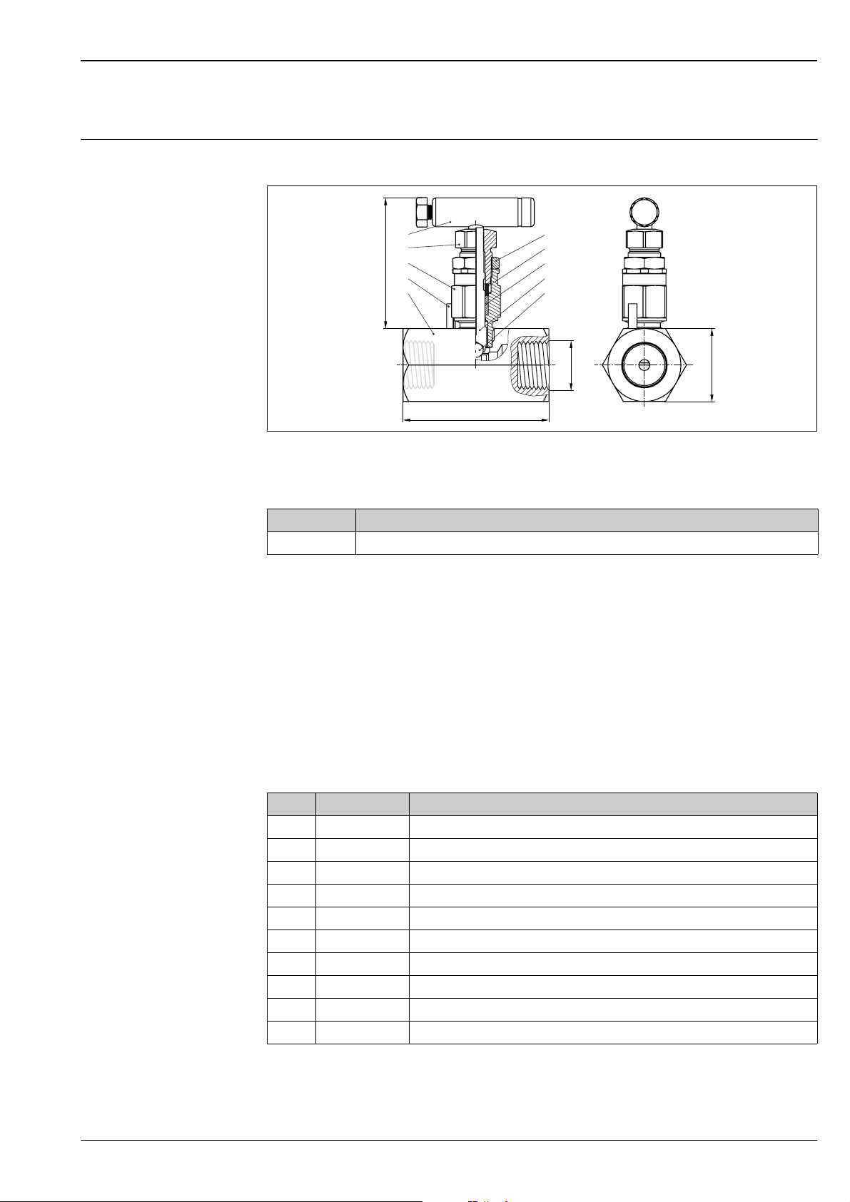
Deltatop DA73V: shut-off valve (accessory)
Version: valve (DA73V-6...)
Dimensions
6
7
5
2.4 (61)
10
1
inch (mm)
Input FNPT1/2; output FNPT1/2
2.5 (63,5)
Weight
Order code Weight
DA73V-6*CC* Approx. 1.8 lbs (0.8 kg)
8
9
3
4
2
NPT½"
1¼" (31,8)
P01-DPxxxxxx-06-xx-00-xx-047
Usage
Universal valve; not suited for humid gases;
DA73V-6*V... and DA73V-6*W...: for pressure ratings up to PN160
Design
• Body: die-pressed part
• Surface: stainless steel
• Stem thread: internal for all versions
• Replaceable valve seat
• Stem with cold rolled surface, back seat and non-rotating cone tip
Materials
Pos. Description Material
1 Valve body ASTM A479-316
2 Ball 316S.S
3Stem seal Teflon
4 Stem ASTM A479-316
5 Bonnet ASTM A479-316
6 Handle assembly 300SERIES SS
7 Packing adjuster ASTM A479-316
8 Jamnut 300SERIES SS
9 Packing follower ASTM A479-316
10 Rollpin 300SERIES SS
Endress+Hauser 41
Page 42
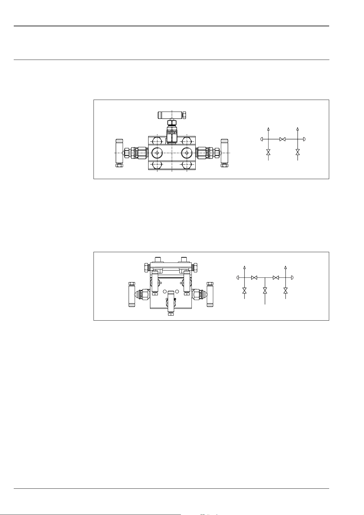
Deltatop DA73M: manifold (accessory)
Usage 3-valve manifold
The manifold is used to connect the impulse pipes to the differential pressure transmitter. Valves 1 and 2 can
be used to separate the transmitter from the impulse pipes.
Valve 3 is used for zero point adjustment between the impulse pipes.
Deltatop DP71B, DP72B, DP73B
3
B
1
2
3
1
A
2
P01-DPxxxxxx-14-xx-xx-xx-015
Left: Milled version (for gases and liquids)
A: Process side; B: Transmitter side
5-valve manifold
The manifold is used to connect the impulse pipes to the differential pressure transmitter. Valves 1 and 2 can
be used to separate the transmitter from the impulse pipes.
Valves 3 and 4 are used for zero point adjustment between the impulse pipes.
Valve 5 offers the possibility of venting or purging the impulse pipes.
B
3
3
1
4
2
5
1
4
5
2
A
P01-DOxxxxxx-14-xx-xx-xx-020
5-valve manifold with venting valve, milled version (for gases and liquids)
A: Process side; B: Transmitter side
42 Endress+Hauser
Page 43
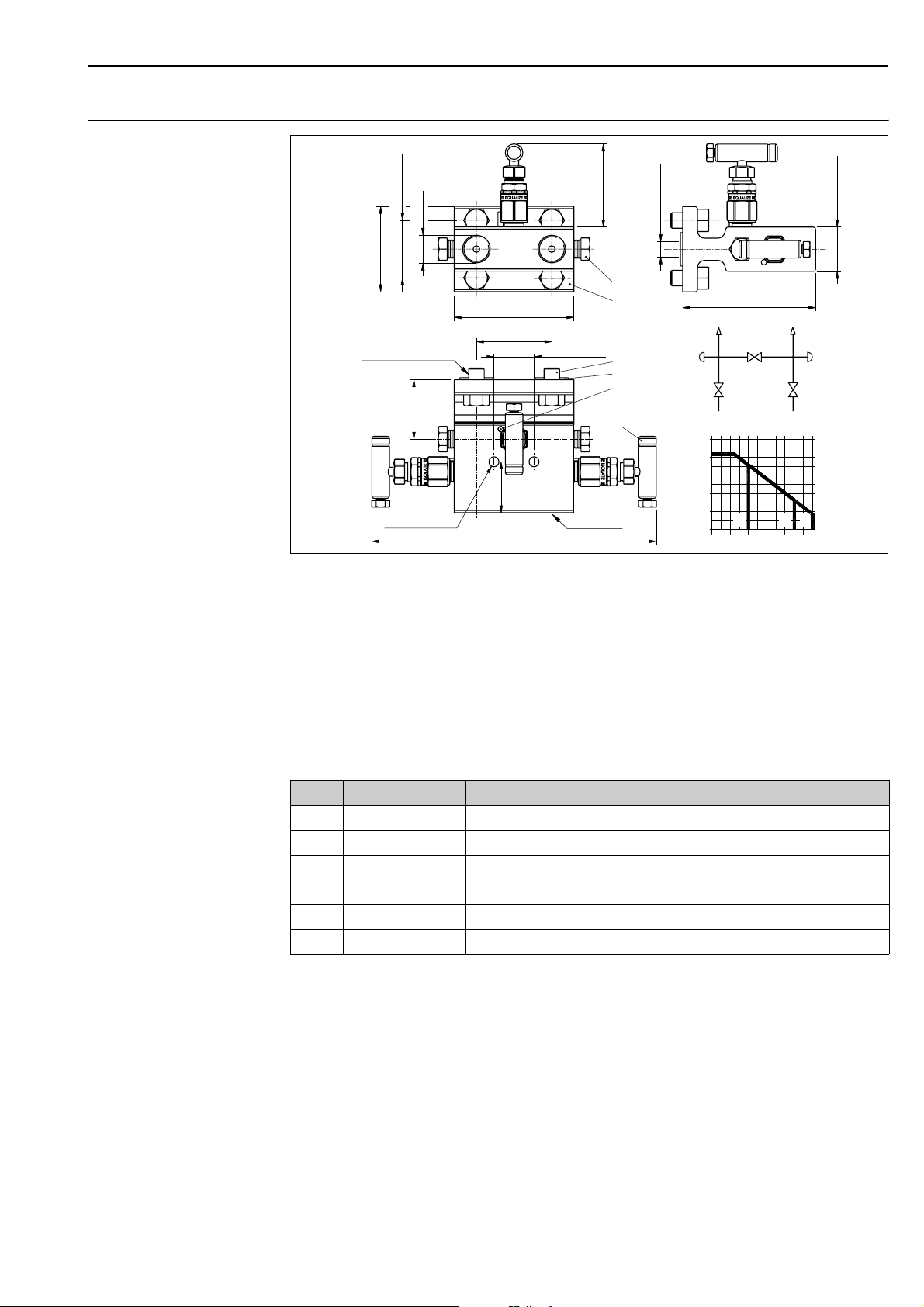
Deltatop DP71B, DP72B, DP73B
Version: 3-valve, manifold
1.63 (41,3)
½NPT
2.41 (61,1)
3.38 (85,7)
2.4 (61)
Ø0.43 (10,9)
5
1
2.13 (54,1)
1.13 (28,7)
½NPT
2
3
4
6
bar
500
400
300
200
100
0
0
inch (mm)
7/16-20 x 3/4 LG
1.68
(42,5)
Ø0.28 (7,1)
8.63 (219,2)
A: Process side; B: Transmitter side;
C: PTFE gasket; D: Pure graphite gasket 1.0460; E: Pure graphite gasket 1.4404
Design
• External stem thread
• Stem with cold rolled surface, back seat and non-rotating needle tip
• Inlet: 1/2 NPT female
• Outlet: IEC61518, type B
• Weight: approx. 4.4 lbs (2.0 kg), including 4 screws with washers and 2 seals
3.75 (95,3)
B
A
200
DC
E
450 550
P01-DOxxxxxx-06-xx-00-xx-050
1.25 (31,8)
°C
Materials
Pos. Description Material
1 Manifold body ASTM A479-316
2 Mounting bolts ASTM A479-316
3 Flange seal Teflon
4 Rollpin 300SERIES SS
5 1/4" NPT hexhd. plug 316 stainless steel
6 Handle assembly 300SERIES SS
Endress+Hauser 43
Page 44
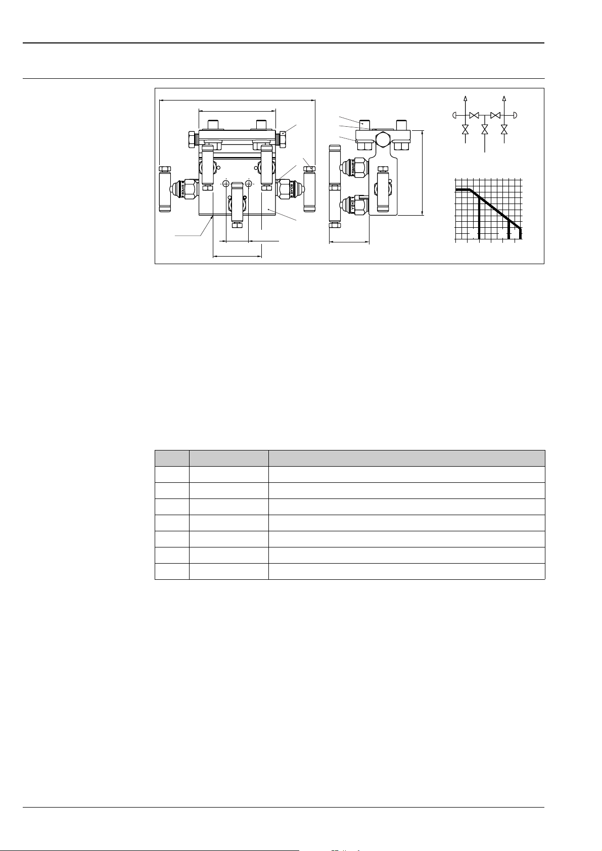
Deltatop DP71B, DP72B, DP73B
Version: 5-valve, manifold
7.18 (182,4)
3.38 (85,9)
2
7
3
1
½NPT
A: Process side; B: Transmitter side; C: Vent
D: PTFE gasket; E: Pure graphite gasket 1.0460; F: Pure graphite gasket 1.4404
1 (25,4)
2.13 (54)inch (mm)
6
5
4
3.75 (95,3)
1.9 (48,3)
Usage
Gas and liquid applications
Design
• External stem thread
• Stem with cold rolled surface, back seat and non-rotating needle tip
• Inlet: 1/2 NPT female
• Outlet: IEC61518, Type B
• Weight: approx. 7.3 lbs (3.3 kg), including 4 screws with washers and 2 seals
bar
500
400
300
200
100
B
C
C
A
D
E
0
200
0
F
550
°C
450
P01-DOxxxxxx-06-xx-00-xx-048
Materials
Pos. Description Material
1 Manifold body ASTM A479-316
2 1/4" NPT hexhd. plug INCONEL625
3 Rollpin 300SERIES SS
4 Washer ASTM A108
5 Flange seal Teflon
6 Mounting bolt ASTM A449-Type 1
7 Handle assembly 300SERIES SS
44 Endress+Hauser
Page 45
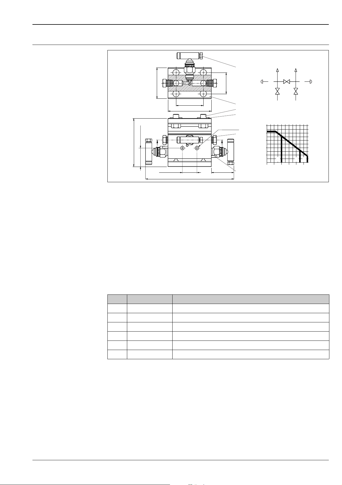
Deltatop DP71B, DP72B, DP73B
Version: 3-valve, manifold, IEC61518, both sides
A-A
6
3.75 (95,2)
inch (mm)
2.41 (61,1)
2.13 (54)
3.38 (85,7)
AA
1.44 (36,6)
1.13 (28,7)
7.13 (181)
1.63 (41,3)
Ø0.28 (7,1)
1.94 (49,3)
1
3
2
4
5
A: Process side; B: Transmitter side; C: Purge valve;
D: PTFE gasket; E: Pure graphite gasket 1.0450; F: Pure graphite gasket 1.4404
B
CC
A
bar
500
400
300
200
100
D
0
0
E
F
200 450 550
P01-DOxxxxxx-06-xx-00-xx-049
°C
Usage
For the compact version of Deltatop
Design:
• Body: die-pressed part
• External stem thread
• Stem with cold rolled surface, back seat and non-rotating needle tip
• Inlet: turned groove ∅18.5 acc. to IEC61518
• IEC61518, type B
• Weight: approx. 4.9 lbs (2.2 kg), including 4 screws with washers and 2 seals
Materials
Pos. Description Material
1 Manifold body ASTM A479-316
2 Flange seal Teflon
3 Mounting bolts ASTM A449-Type 1
4 1/4" NPT hexhd. plug INCONEL625
5 Rollpin 300SERIES SS
6 Handle assembly 300SERIES SS
Endress+Hauser 45
Page 46
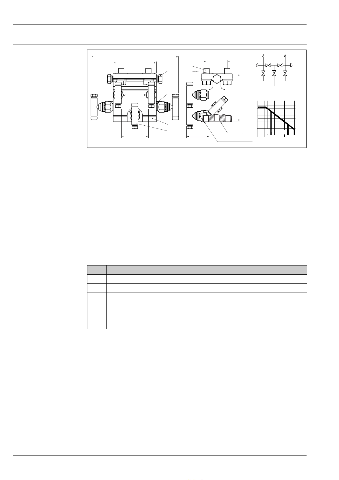
Deltatop DP71B, DP72B, DP73B
Version: 5-valve, manifold, IEC61518, both sides
8.18 (207,6)
3.38 (85,9)
2
3
1
2.13 (54)
inch (mm)
A: Process side; B: Transmitter side; C: Vent;
D: PTFE gasket; E: Pure graphite gasket 1.0460; F: Pure graphite gasket 1.4404
6
5
4
2.4 (61)
1.63 (41,3)
3.75 (95,3)
¼NPT
7/16-20 UNF-2B
Usage
For the compact version of Deltatop
Design
• Body: die-pressed part
• External stem thread
• Stem with cold rolled surface, back seat and non-rotating needle tip
• Inlet: turned groove ∅18.5 acc. to IEC61518
• Outlet (to transmitter): IEC61518, type B
• Outlet (test/vent): 1/4 NPT female with screw plug
• Weight: approx. 3.3kg (7.3 lbs), including 4 screws with washers and 2 seals
bar
500
400
300
200
100
B
C
C
A
D
E
0
200
0
F
550
°C
450
P01-DOxxxxxx-06-xx-00-xx-051
Materials
Pos. Description Material
1 Manifold body ASTM A479-316
2 1/4" NPT hexhd. plug ASTM A479-316
3 Rollpin 300 SERIES SS
4 IEC flange seal GRAFOIL
5 Mounting bolt 7/16-20 X 1" LG. ASTM A479-316
6 Handle assembly 300SERIES SS
46 Endress+Hauser
Page 47
Deltatop DP71B, DP72B, DP73B
Product structure DA73M
300 Version
AB2 3 valve, 316L, milled
BB2 5 valve, 316L, milled, vent
KA2 3 valve, 316L, IEC51528, both side
LA2 5 valve, 316L, IEC61518, both sides, vent
YY9 Special version, to be specified
310 Gasket
B PTFE, 200°C / 392°F
D Graphite / Graphoil
Y Special version, to be specified
320 Process connection
BFNPT1/2
E IEC61518
Y Special version, to be specified
330 Seals; Screws
B PTFE; UNF7/16, max 420bar
D Viton; UNF7/16, max 420bar
K Graphite; UNF7/16, max 420bar
Y Special version, to be specified
540 Additional option
EB Mounting bracket, stainless steel
E1 EN10204-3.1 material (wetted parts) inspection certificate
E2 EN10204-3.1 material, NACE MR0175 (wetted parts) inspection certificate
E5 Cleaned from oil+grease
E6 Oxygen service
895 Marking
Z1 Tagging (TAG), see additional spec.
Product structure DA73V
250 Version; Gasket
6 Valve; PTFE gasket < 200°C / 392°F
8 Valve; pure graphite gasket < 300°C / 572°F
9 Special version, to be specified
260 Material
F316L
Y Special version, to be specified
270 Inlet
DFNPT1/2
Y Special version, to be specified
280 Output
CFNPT1/2
Y Special version, to be specified
530 Additional option
D1 EN10204-3.1 material (wetted parts) inspection certificate
D2 EN10204-3.1 material, NACE MR0175 (wetted parts) inspection certificate
D5 Cleaned from oil+grease
D6 Oxygen service
Endress+Hauser 47
Page 48
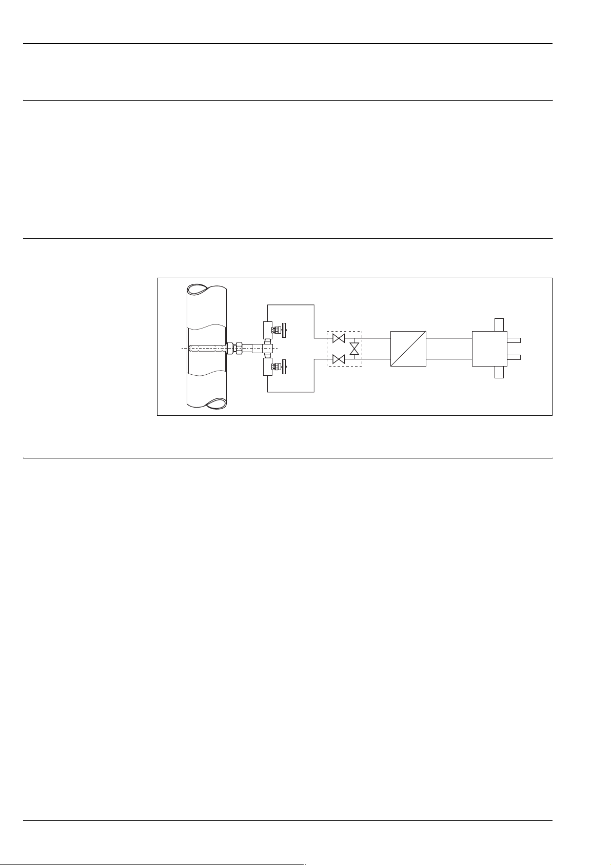
Deltatop DP71B, DP72B, DP73B
Purge unit
Usage With flow measurements of waste gases or soiled air, solid particles often settle at the profile of the Pitot tube
and, depending on the degree of soiling, reduce the measuring accuracy or even interfere with the functionality
of the Pitot tube.
In many applications, recurrent manual cleaning of the Pitot tube is not a feasible solution. Demounting the
probe, thorough cleaning and remounting are often too cost-intensive and time-consuming. Furthermore, no
measuring data are available during the cleaning procedure.
The purge unit helps to perform fully automated and effortless cleaning.
The application of a purge unit is recommended for a particle concentration of more than 1.17 gr/yd
(100 mg/m3). The usability of the purge unit is restricted for humid or adhesive solid particles. The maximum
permissible solid content depends on the abrasiveness and size of the particles and has to be examined
separately in each case.
System design The purge unit consists mainly of a purging block with a 2-way valve which can be directly triggered. A
customer-provided relay or a PLC can be used to trigger the two solenoid valves.
3
MV2
Purge Unit
MV1
P01-DP62Pxxx-14-00-00-00-002
A
A
MV1, MV2: Solenoid valves; A: Air purge connection
DA73M
Deltabar
Dp
I
Mounting 1. The purge unit is directly mounted to the differential pressure transmitter with the supplied screws and
seals.
2. The vent valves supplied together with the differential pressure transmitter are screwed into the purge
unit. The impulse pipes are mounted on the opposite side of the transmitter. This ensures that not only
the Pitot tube but also the measuring chambers of the differential pressure transmitter are purged and
cleared from any deposit.
3. The connections for the purging air are located at the bottom of the purge unit.
48 Endress+Hauser
Page 49
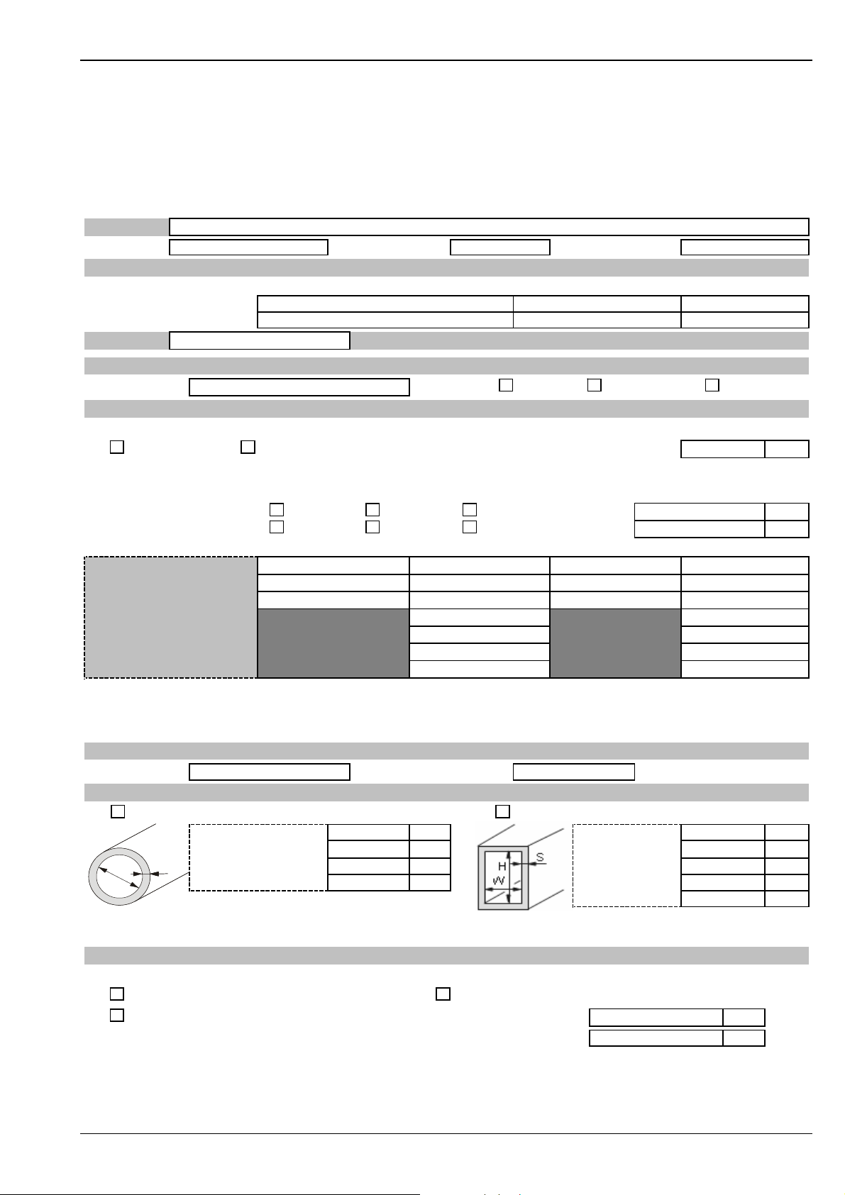
Deltatop DP71B, DP72B, DP73B
Sizing sheet - data sheet
Sizing Sheet - data sheet / Pitot Tube Sheet 1/2
Fields marked with * are mandatory to be filled-in
Project:
Customer: Project-No.: Contact partner:
Order Code
Order code Order no.* Position(s) *
Primary element
Transmitter
Tag:
Main Parameter
Medium: * Status * Gas Liquid Steam
Operating Conditions
Pressure *
absolute gauge ambient pressure:
Only for gases:
Flow rate * Reference temp.:
Density * Reference pressure:
Requested flow:
Pressure: *
Temperature: *
Density: 1)
Viscosity: 1)
Z-factor: 1,2)
Isentropic index: 1,2)
The sizing will be based on the maximum requested flow and nominal pressure and temperature.
The maximum requested flow will be set as upper range value.
1) For clearly specified fluids (e.g. water or air) those entries are not mandatory.
2) For gases only. If there are no values available the sizing will be based on standard values or the ideal gas law.
Flowmeter
Nominal width: * Pressure rating:*
Pipe (round) * Rectangular duct
S
D
D
The exact specification of the internal dimensions and wall thickness is absolutely necessary.
Nominal widths of DIN pipes DNxxx are not sufficient. Nominal widths of ANSI pipes including schedules according to ASME are sufficient.
S
i
i
i
i
Additional Data
Temperature transmitter not applicable for DP71D
without temperature sensor PT100 sensor with 4…20mA transmitter
PT100 sensor without transmitter Lower range value
For gauge pressure the ambient pressure is additionally required if different from sea level.
The values for requested flow resp. density of the medium are based on the following conditions:
operating normal standard (acc. to reference conditions)
minimum nominal maximum
*
Mounting position s. sheet 2Pipe dimensions *
Inner diameter (DI): Duct height (H) :
Wall thickness (S): Duct width (W) :
Isolation thickness:
Pipe material: Isolation thickness:
Upper range value
Wall thickness (S):
Pipe material:
unit *
unitunit
unit
unit
unit
FLOWDATA3-EN
Endress+Hauser 49
Page 50
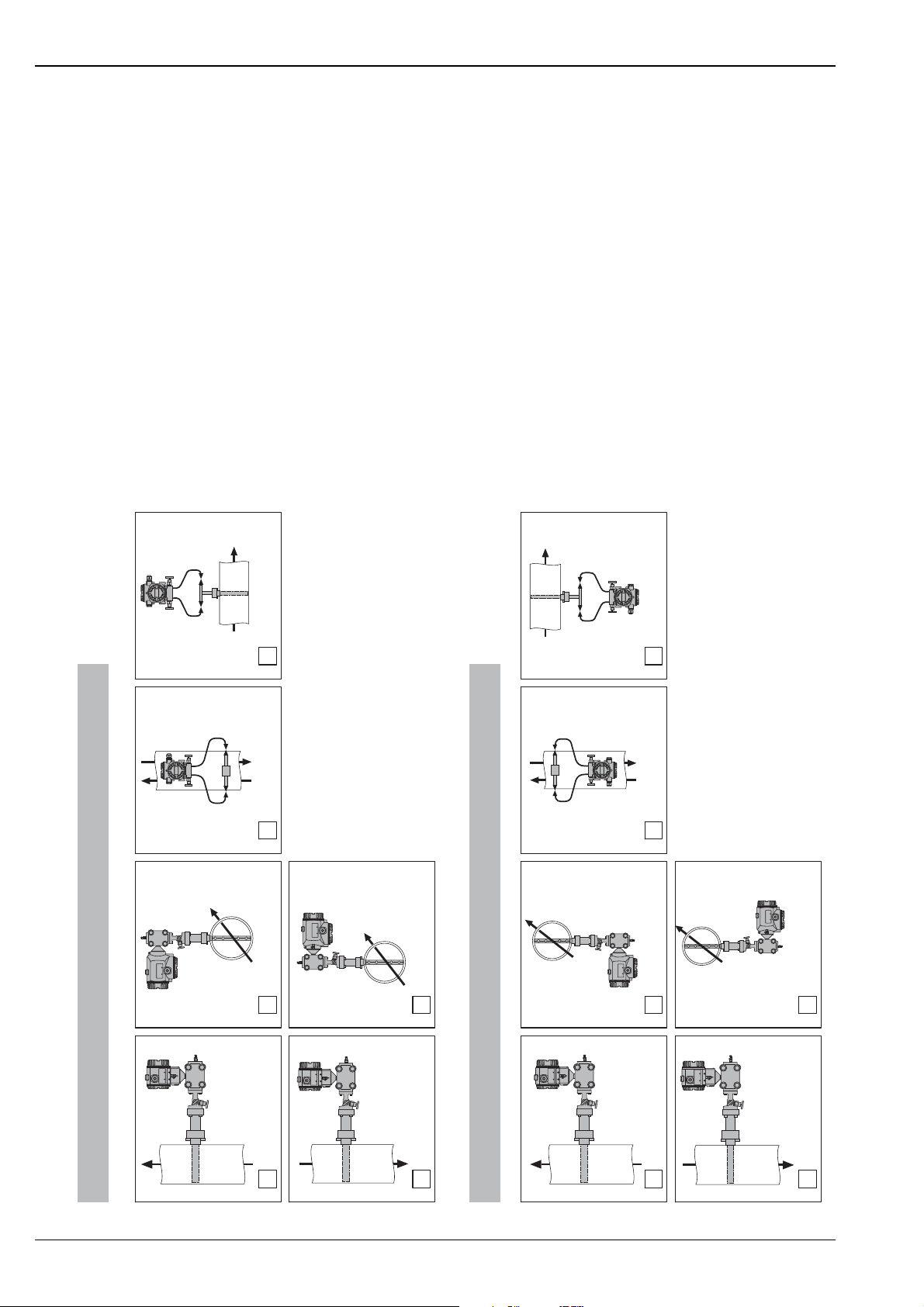
Deltatop DP71B, DP72B, DP73B
remote, horizontal
remote, vertical
compact, horizontal
above/on top
upwards/downwards
mounted left
mounted right
remote, horizontal
remote, vertical
compact, horizontal
below / at bottom
upwards/downwards
mounted left
mounted right
Sizing Sheet - Mounting Position / Pitot Tube
Gas:
compact, vertical
upwards
downwards
Liquid / Steam:
compact, vertical
upwards
downwards
FLOWDATA4_en
50 Endress+Hauser
Page 51

Deltatop DP71B, DP72B, DP73B
Instructions for completing the sizing sheet - data sheet
• The order code of a primary element does not completely describe the final device. Further information is
required. The optimized sizing and calculation of the primary element is based on the requested information
about process parameters and pipe dimensions etc. Additionally Endress+Hauser checks if the information
provided matches the order code of the device. Furthermore, the feasibility of the measuring point also has
to be examined. A fully completed questionnaire, including information on the project, order codes and tag
number, ensures the correct assignment of primary elements to differential transmitters and accessories
during order processing.
• The "Sizing sheet - data sheet" can be filled in and printed using the Endress+Hauser Applicator sizing
software. All required data can be entered or are available in the database.
• All fields marked with an asterisk * have to be completed. The order cannot be processed and device
production cannot commence before these points are clarified.
• All parameters have to be filled in with their value and the complete and correct unit (e.g. flow rate in Sm
h and not m3/h for flow at normal conditions).
Section Field / parameter Explanation of the entry Mandatory
A1)B1)C
Project
Project
Customer
Project no.
Order code
Primary element Order code Order code of the selected primary element
Order no.*
Positions*
Transmitter Order code Order code of the associated differential pressure transmitter.
Order no. *
Positions*
Tag
Tag Tag no. for clear assignment of primary element and dp transmitter.
Main parameter
Medium*
Status*
Operating conditions
Process The differential pressure calculation is based on correct information concerning the process
Pressure*
(absolute or gauge)
Ambient pressure The primary element calculation is always based on absolute static pressure in the pipe. If the static
Flow rate*
Density*
(at operating / normal
/ standard conditions)
Operating conditions For gases only:
Order-specific customer data
Order position, to be assigned to this data sheet. yes
Order position of the dp transmitter, to be assigned to the primary element. yes
Exact designation of the fluid with name (e.g. water) or chemical formula (e.g. CH
Type of fluid or state of aggregation of the medium at the given operating conditions - gas, liquid or
steam. Depending on this information, further data may have to be entered.
conditions. Generally, the layout point for the primary element is the maximum requested flow rate
at nominal pressure and nominal temperature.
Clearly state whether the static pressure is given as absolute or gauge pressure. yes yes
pressure is given as gauge pressure, the average ambient pressure (if different from sea level) or
alternatively the altitude of the location above sea level also has to be specified.
For gases only:
Values for the flow rate and/or density can be related to the actual operating conditions (nominal
pressure and temperature) or to normal or standard conditions. The resulting difference may be
large depending on the pressure and temperature. Please check the data carefully. Furthermore,
clearly specify the units for the flow rate and density (e.g. flow rate in Sm
at normal conditions).
The values for the flow rate or density are related to the nominal process conditions (pressure and
temperature).
3
/h and not m3/h for flow
).
4
yes
yes
yes
yes
3
/
1)
Endress+Hauser 51
Page 52

Deltatop DP71B, DP72B, DP73B
Section Field / parameter Explanation of the entry Mandatory
A1)B1)C
Normal conditions For gases only:
The values for the flow rate or density are related to normal conditions (pressure and temperature):
Pressure: 14696psi abs. (101.325 kPa abs.)
Temperature: 59°F (0°C) 273.15 K
Standard conditions
(acc. to reference
conditions)
For gases only:
The values for the flow rate or density are related to standard conditions (pressure and
temperature):
Pressure: 14696psi abs. (101.325 kPa abs.)
Temperature: 59°F (0°C) 273.15 K
If other reference conditions are to be considered, the values for these conditions have to be clearly
specified.
Reference temp. Reference temperature at standard conditions yes
Reference pressure Reference pressure at standard conditions yes
Req. flow Specification of the desired measuring range (minimum to maximum) and of the operating point
(nominal). The operable flow range is typically between 1:3 and 1:6 (minimum : maximum). An
operable flow range of more than 1:10 usually requires cascading (split range) of several differential
pressure transmitters (→ ä 8). Too large an operable flow range between the nominal and the
maximum flow can result in an increased measuring uncertainty at the operating point and should
be avoided.
Pressure Static pressure in the pipe upstream (plus side) of the primary element. yes yes
Temperature Temperature of the fluid at the primary element. yes yes
Fluid properties Clearly defined liquids and gases, such as steam, oxygen, nitrogen, pure water or ethanol, do not
require further fluid property entries. All necessary information about these data is easily accessible
in the relevant literature. Mixtures (e.g. natural gas) or brand names (e.g. Shell motor oil) do not
provide sufficient information for calculation purposes. More information is required. If the fluid
properties of a mixture are not clear, a list of ingredients and their composition can be attached to
this datasheet for clarification.The Endress+Hauser Applicator sizing tool provides users with a large
medium database with all the necessary fluid properties for a wide variety of fluids.
Density The density is an essential input value of the flow calculation. This field must be completed for
mixtures and brand names.
Viscosity The influence of the viscosity value on the calculation is normally very small but the Reynolds No. is
a function of the viscosity. This may be a limiting factor for the measurement especially with highly
viscous liquids.
Z-factor For gases only:
The compressibility factor Z has an influence on the density especially at higher pressures and/or
higher temperatures. If the density is given at normal or standard conditions this may have quite a
big impact on the calculation result. If this value is not available, the calculation will be performed
with the factor set to 1 or, in case of clearly defined mixtures, with a factor calculated or estimated
from the ingredients.
Isentropic index For gases only:
The isentropic index (or specific heat ratio) is required to calculate the expansion factor. If the value
is not available, the calculation will be performed with standard values:
1.65 for monoatomic gases (e.g. Helium He)
1.4 for diatomic gases (e.g. nitrogen N
1.28 for triatomic gases (e.g. carbon dioxide CO
)
2
)
2
Flowmeter
Nominal width* Nominal width of the pipe according to the relevant standards, e.g. 8" (ASME) or DN200 (DIN) yes
Pressure rating* Pressure rating of the selected connection (e.g. flange) according to the relevant standard, e.g.
Cl.600lbs (ASME) or PN40 (DIN).
Pipe dimensions
Pipe (round) /
Selection of the type of duct. Only one option can be selected. yes
Rectangular duct
yes
yes
yes yes
yes
yes
yes
yes
yes
1)
52 Endress+Hauser
Page 53

Deltatop DP71B, DP72B, DP73B
Section Field / parameter Explanation of the entry Mandatory
A1)B1)C
yes yes
yes
yes
yes
Additional data
Temperature
transmitter*
Mounting position
Inner diameter (DI) Mean inner diameter of the pipe. The precise inner diameter of the pipe forms the basis for
Duct height (H) /
Duct width (W)
Wall thickness (S) The wall thickness of the duct is added to the total length of the Pitot tube. Precise specification is
Isolation thickness Thickness of a possible thermal isolation of the pipe or of other covering shells. The isolation
Pipe material Specification of the correct pipe material. The selected material of the mounting components should
Without temperature
sensor
PT100 sensor without
transmitter
Mounting position A suitable mounting position in accordance with the situation on site can be chosen by marking the
calculating the differential pressure and determines the length of the probe in the pipe. Incorrect
specifications when ordering result in corresponding measuring errors or may mean that the probe
cannot be mounted properly or cannot be mounted at all. The inner diameter of the pipe is equal to
the length of the probe in the pipe. However, the inner diameter is NOT equal to the nominal
diameter. A pipe of nominal diameter DN200 according to ISO may have inner diameters between
194 mm and 215 mm depending on the pressure rating. For pipes according to ASME, it suffices to
specify the nominal diameter and the schedule number.
With rectangular ducts the inner pipe diameter is replaced by the inner dimensions of the duct
(height and width). These dimensions are used to calculate the cross-sectional area, which is
needed to calculate the differential pressure. The Pitot tube is usually mounted parallel to the longer
side of the rectangular duct. Therefore, this dimension determines the length of the Pitot tube in the
pipe. Incorrect specifications when ordering result in corresponding measuring errors or may mean
that the probe cannot be mounted properly or cannot be mounted at all.
essential.
thickness is added to the length of the neck of the probe. Failure to specify this information may
mean that the Pitot tube cannot be mounted properly (→ ä 24).
match the pipe material in order to ensure weldability.
Temperature sensors can only be integrated into device types DP72B and DP73B and for pressure
ratings up to 300lbs (PN40).
An integrated temperature sensor is not required. yes
A PT100 temperature sensor is required, but without a transmitter however. yes
check box below the pictogram. The mounting position selected has to match the order code.
Endress+Hauser will check if any features in the order code mutually exclude one another.
1)
1) A: Mandatory for differential pressure calculation;
B: Mandatory for device selection (material, pressure rating etc.);
C: Mandatory for order processing (assignment of devices)
Endress+Hauser 53
Page 54

Deltatop DP71B, DP72B, DP73B
54 Endress+Hauser
Page 55

Deltatop DP71B, DP72B, DP73B
Endress+Hauser 55
Page 56

Instruments International
Endress+Hauser
Instruments International AG
Kaegenstrasse 2
4153 Reinach
Switzerland
Tel. +41 61 715 81 00
Fax +41 61 715 25 00
www.endress.com
[email protected]
TI441P/00/EN/09.09
71102952
CCS/FM+SGML 6.0
71102952
 Loading...