

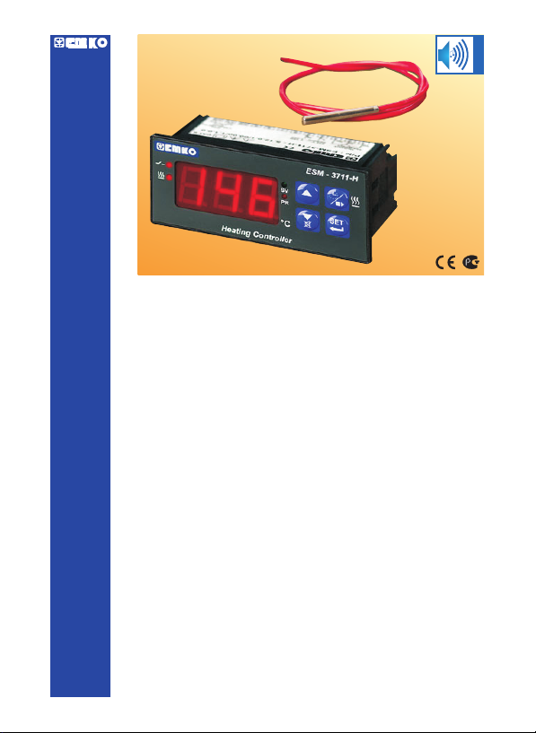
ESM- 77 x 35 DIN3711-H Size
Digital, ON / OFF Temperature Controller
- 3 Digits display
- PTC Input or,
J type Thermocouple Input or,
K type Thermocouple Input or,
2-Wire PT 100 Input or,
2-Wire PT 1000 Input (It must be determined in order)
- ON/OFF temperature control
- Adjustable temperature offset
- Set value low limit and set value high limit boundaries
- Relay or SSR driver output
- Digital Input (Cooking time start/stop input)
- Adjustable cooking time from front panel
- Temperature control according to the cooking time (Timer)
- User can select to start cooking time (Timer) when temperature
reaches to the set value
- Temperature control with manual heating function
- Alarm parameters
- Adjustable internalbuzzer accordingto cooking time, probe
defect and alarmstatus
- Button protection
- Password protection for programming section
Internal Buzzer
ESM- 77x35 DIN Size Heating Controller3711-H
Instruction Manual. ENG ESM-3711-H 02 V01 07/08

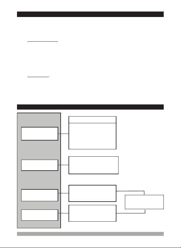
ABOUT INSTRUCTION MANUAL
Instruction manual of ESM-3711-H Temperature Controller consists of two main sections.
Explanation of these sections are below. Also, there are other sections which include order
information and technical specifications of the device. All titles and page numbers in instruction
manual arein section. Usercan reachto any titlewith sectionnumber.
Installation:
physical andelectrical installationof the deviceto thesystem are explained.
Operation and Parameters:
parameters areexplained.
physical andelectrical mounting orusing the device.
“CONTENTS”
In this section, physical dimensions of the device, panel mounting, electrical wiring,
In thissection user interface of the device, accessingto the parameters, description ofthe
Also in these sections, there are warnings to prevent serious injury while doing the
Explanation ofthe symbolswhich are usedin thesesections are givenbelow.
This symbol is used for safety warnings. User must pay attention to these
warnings.
c
This symbolis used todetermine the dangeroussituations as aresult of anelectric
shock. Usermust payattention to thesewarnings definitely.
a
This symbolis used todetermine the importantnotes about functionsand usage of
the device.
i
2

Contents
1.PREFACE............................................................................................................................................
1.1 GENERAL SPECIFICATIONS
1.2 ORDERING INFORMATION
1.3 WARRANTY
1.4 MAINTENANCE
2.INSTALLATION....................................................................................................................................
2.1 GENERAL DESCRIPTION
2.2 FRONT VIEW AND DIMENSIONS OF ESM-3711-H TEMPERATURE CONTROLLER
2.3 PANEL CUT-OUT
2.4 ENVIRONMENTAL RATINGS
2.5 PANEL MOUNTING
2.6 INSTALLATION FIXING CLAMP
2.7 REMOVING FROM THE PANEL
3.ELECTRICAL WIRINGS......................................................................................................................
3.1 TERMINAL LAYOUTAND CONNECTION INSTRUCTIONS
3.2 ELECTRICAL WIRING DIAGRAM
3.3 VIEW OF THE DEVICE LABEL
3.4 SUPPLY VOLTAGE INPUT CONNECTION OF THE DEVICE
3.5 TEMPERATURE INPUT SENSOR CONNECTION
3.5.1
TC (THERMOCOUPLE) CONNECTION
3.5.2
PTC CONNECTION
3.5.3
PT-100 AND PT-1000 CONNECTION
3.6 GALVANIC ISOLATION TEST VALUES OF ESM-3711-H TEMPERATURE CONTROLLER
3.7 OUTPUT CONNECTIONS
3.7.1 RELAY OUTPUT CONNECTION
3.7.2 SSR DRIVER OUTPUT CONNECTION
4.FRONT PANEL DEFINITION ANDACCESSING TO THE MENUS....................................................
4.1 OBSERVATION OF SOFTWARE REVISION ON THE DISPLAYS
4.2 CHANGING AND SAVING SETVALUE
4.3
CHANGING AND SAVING COOKINGTIME (TIMER) PARAMETER VALUE
4.4 PROGRAMMING MODE PARAMETER LIST
4.5
COOKING TIME (TIMER) ON/OFF OPERATION
4.5.1
COOKING TIME (TIMER) ON/OFF OPERATION WITH COOKING BUTTON
4.5.2
COOKING TIME (TIMER) ON/OFF OPERATION WITH COOKING TIME START/STOP
INPUT
4.6 OPERATION GRAPHICS OF ESM-3711-H HEATING CONTROLLER
4.7 EASY ACCESS DIAGRAM OF PROGRAMMING MODE PARAMETERS
4.8 ENTERING TO THE PROGRAMMING MODE, CHANGING AND SAVING PARAMETERS
5.FAILURE MESSAGES IN ESM- HEATING CONTROLLER....................................................
6.SPECIFICATIONS................................................................................................................................
3711-H
Page 5
Page 7
Page 12
Page 19
Page 29
Page 30
3

EU DECLARATION OF CONFORMITY
Manufacturer Company Name :
Manufacturer Company Address:
The manufacturer hereby declares that the product conforms to the following standards and
conditions.
Product Name
Model Number :
Type Number :
Product Category :
Conforms to the following directives :
73 / 23 / EEC The Low Voltage Directive as amended by 93 / 68 / EEC
89 / 336 / EEC The Electromagnetic Compatibility Directive
Has been designed and manufactured according to the following specifications
EN 61000-6-4:2001 EMC Generic Emission Standard for the Industrial Environment
EN 61000-6-2:2001 EMC Generic Immunity Standard for the Industrial Environment
EN 61010-1:2001 Safety Requirements for electrical equipment for measurement, control and
laboratory use.
Emko Elektronik A.S.
DOSAB, Karanfil Sokak, No:6, 16369 Bursa, Turkiye
: Heating Controller
ESM-3711-H
ESM-3711-H
Electrical equipment for measurement, control and laboratory
use
4
1.Preface
ESM-3711-H series heating controllers are designed formeasuring andcontrolling temperature.
They canbe used in many applicationswith their easyuse, On/ Offcontrol form and cooking time
properties.
Some applicationfields whichthey are usedare below:
Application Fields
Glass
Food
Plastic
Petro-Chemistry
Textile,Automative
Machine Production Industries
etc...
Applications
Heating
Baking Ovens
Incubators
Storages
Air Conditioning
Etc...
1.1 General Specifications
ESM-3711-H
Power Supply
Input
Temperature Sensor
Input
Standard
230 V (±15 ) , 50/60HzV %
Optional Supply Input
115 V (±15 ) , 50/60HzV %
24 V (±15 ) , 50/60HzV %
24 V (-15 ),
W %,+10%
50/60Hz
12 V (±15 ) , 50/60HzW %
PTC
JorKTypeTC
2 Wire PT 100
2 Wire PT 1000
Standard
Output-1 (Relay
Output)
Optional
Output-1
(SSr Driver Output)
Control Output
Alarm Output
Control Output
Alarm Output
Heating
Function
ON/OFF Operation
5
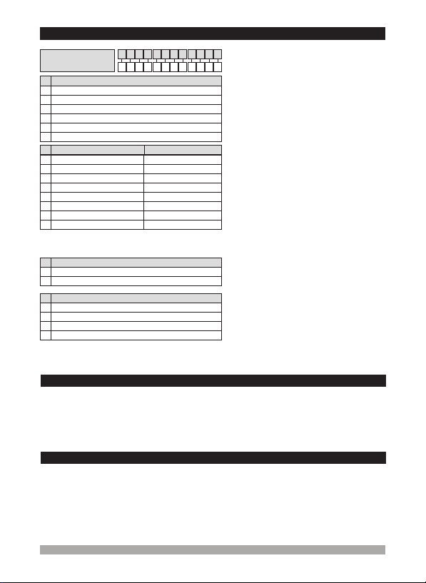
1.2 Ordering Information
/
-50°C
-19.9°C
-50°C
-19.9°C
-50°C
-19.9°C
00
Scale(°C)
0°C
0°C
/
U
VWZ/
800°C
999°C
400°C
99.9°C
150°C
99.9°C
400°C
99.9°C
All order information ofESM-3711-H
Temperature Controller are given on the
table at left. User may form appropriate
device configuration from information and
codes that at the table and convert it to the
ordering codes.
Firstly, supply voltage then other
specifications must be determined. Please
fill the order code blanks according to your
needs.
Please contact us, if your needs are
out ofthe standards.
Þ
VZVac,
Þ
applied.
ÞW
c
Vdc,
Vdc or Vac can be
ESM-3711-H (77x35DIN Size)
Supply VoltageA
24V ( -15%,+10% ) 50/60HzW
2
24V ( ± 15% ) 50/60HzV
3
115V ( ± 15% ) 50/60HzV
4
230V ( ± 15% ) 50/60HzV
5
12V ( ± 15% ) 50/60HzW
6
9
Customer
Input Type
BC
J, Fe CuNi IEC584.1(ITS90)
05
10
K, NiCr Ni IEC584.1(ITS90)
PT 100, IEC751(ITS90)
11
PT 100, IEC751(ITS90)
09
PTC (Note-1)
12
PTC (Note-1)
15
PT 1000, IEC751(ITS90)
14
PT 1000, IEC751(ITS90)
13
Note-1 : If input type is selected PTC ( BC = 12 or BC = 15), PTC
Temperature sensor is given with the device. For this reason,
PTC sensor type ( V ) must be declared in ordering information.
E
Output-1
1
Relay Output (resistive load 10 A@250 V , 1 NO + 1NC )V
2
SSR Driver Output (Maximum 15 mA@5 V )Z
Temp.Sensor which is given with ESM-3711-H
V
None
0
PTC-M6L40.K1.5(PTC Air probe with 1.5 m silicon cable)
1
PTCS-M6L30.K1.5(PTC Liquid probe with 1.5 m silicon cable)
2
Customer
9
ABCD E FGHI /
000100
1.3 Warranty
EMKO Elektronik warrants that the equipment delivered is free from defects in material and
workmanship. This warrantyis providedfor a period oftwo years. Thewarranty period starts from
the delivery date. This warranty is in force if duty and responsibilities which are determined in
warranty documentand instructionmanual performs bythe customercompletely.
1.4 Maintenance
Repairs should only be performed by trained and specialized personnel.Cut powerto the device
before accessinginternal parts.
Do not clean the case with hydrocarbon-based solvents (Petrol, Trichlorethylene etc.). Use of
these solventscan reduce the mechanical reliability of thedevice. Usea cloth dampened in ethyl
alcohol orwater toclean the externalplastic case.
6

2.Installation
Before beginning installation of this product, please read the instruction
manual andwarnings belowcarefully.
c
In package,
- Onepiece unit
- Two pieces mounting clamps
- Onepiece instructionmanual
A visual inspection of this product for possible damage occured during shipment is
recommended before installation. It is your responsibility to ensure that qualified
mechanical andelectrical techniciansinstall this product.
If there is danger of serious accident resulting from a failure or defect in this unit, power
off thesystem and the electricalconnection ofthe device fromthe system.
The unit is normally supplied without a power supply switch or a fuse. Use power switch
and fuseas required.
Be sure to use the rated power supply voltage to protect the unit against damage and to
prevent failure.
Keep the power off until all of the wiring is completed so that electric shock and trouble
with theunit canbe prevented.
Never attempt to disassemble, modify or repair this unit. Tampering with the unit may
results inmalfunction, electricshock or fire.
Do notuse theunit in combustibleor explosivegaseous atmospheres.
During the equipment is putted in hole on the metal panel while mechanical installation
some metalburrs cancause injury onhands, youmust be careful.
Montage of the product on a system must be done with it’s fixing clamps. Do not do the
montage of the device with inappropriate fixing clamp. Be sure that device will not fall
while doingthe montage.
It is your responsibility if this equipment is used in a manner not specified in this
instruction manual.
separate
7
2.1 General Description
Front Panel
IP65 protection
NEMA 4X
Panel surface
(maximum thickness 15 mm / 0.59 inch)
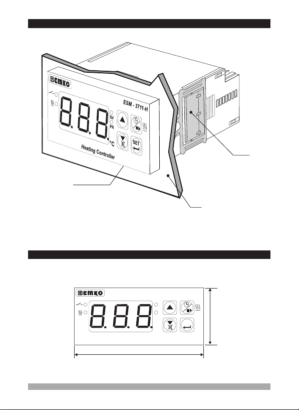
2.2 Front View and Dimensions of ESM-3711-H Temperature Controller
ESM - 3711-H
SV
PR
SET
°C
Heating Controller
Mounting Clamp
35 mm / 1.38 inch
77 mm / 3.03 inch
8
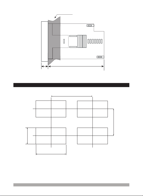
Maximum 15 0.59 inchmm /
2.3 Panel Cut-Out
29 mm / 1.14 inch
4 mm /0.16 inch
71 mm / 2.79 inch
58.5 mm / 2.30 inch
110 mm / 4.33 inch (min)
50 mm / 1.97 inch (min)
9

2.4 Environmental Ratings
Operating Conditions
Operating Temperature :
Max. Operating Humidity :
Altitude :
Forbidden Conditions:
Corrosive atmosphere
Explosive atmosphere
c
Home applications(The unitis only forindustrial applications)
2.5 Panel Mounting
0to50°C
90 Rh (non-condensing)
%
Up to 2000 m.
1
2
1-Before mounting the device in your
panel, make sure that the cut-out is of
the rightsize.
2-Insert the device through the cut-out.
If the mounting clamps are on the unit,
put out them before inserting the unit to
the panel.
During installation into a metal panel, care should be taken to avoid injury from
metal burrs which might be present. The equipment can loosen from vibration
and become dislodged if installation parts are not properly tightened. These
precautions forthe safetyof the personwho doesthe panel mounting.
c
10

2.6 Installation Fixing Clamp
1
Montage ofthe unit to a systemmust be done withit’s ownfixing clamps. Donot
do the montage of the device with inappropriate fixing clamps. Be sure that
device willnot fallwhile doing themontage.
c
2.7 Removing from the Panel
Before starting to removethe unit from panel, power off the unit and the related
system.
c
The unit is designed for panel
mounting.
1-Insert the unit in the panel cut-out
from thefront side.
2- Insert the mounting clamps to the
fixing sockets that located left and
right sidesof device and make theunit
completely immobilewithin thepanel
2
1-Pull mounting clamps from left and
right fixingsockets.
2-Pull theunit through thefront side of
the panel
1
2
11

3.Electrical Wiring
You must ensure that the device is correctly configured for your application.
Incorrect configurationcould result indamage to the process beingcontrolled,
and/or personal injury. It is your responsibility, as the installer, to ensure that
c
the configurationis correct.
Device parameters has factory default values. These parameters must be set
according tothe system’sneeds.
Only qualified personnel and technicians should work on this equipment. This
equipment contains internal circuits with voltage dangerous to human life.
There issevere dangerfor human lifein thecase of unauthorizedintervention.
c
Be sure to use the rated power supply voltage to protect the unit against
damage andto preventfailure.
c
Keep thepower off until all ofthe wiring is completed sothat electric shock and
trouble withthe unitcan be prevented.
c
3.1 Terminal Layout and Connection Instructions
123 4567 89101112
a
Screw driver
0,8 x3 mm
Torque
0,5 Nm
Max. 2.5 mm / 0.098 inch
Wire Size:
14 AWG/1 mm²
Solid /Stranded
12

3.2 Electrical Wiring Diagram
Electrical wiring of the device must be the same as ‘Electrical Wiring Diagram’
below toprevent damageto the processbeing controlledand personnel injury.
c
P/N : 711-HESM-3
CAT II
Yc
OUTPUT
10 A@250 V V
NO NCC
123 4567 89101112
a
(-)
(+)
For SSr Output
Relay or SSR
Driver Output
Supply Voltage Input
V
V ( ± 15% ) 50/60 Hz - 1.5
230 VA
V
V ( ± 15% ) 50/60 Hz - 1.5
115 VA
V
24 V ( ± 15% ) 50/60 Hz - 1.5
W
24 V ( -15%,10% ) 50/60 Hz - 1.5
(It must be determined in order)
TemperatureSensor Input is inCAT IIclass.
i
L N L(+) N(-)
Cooking Time(Timer)
DIGITAL
INPUT
Start/Stop Input
VA
VA
PTC, PT-100
PT-1000
TC
Temperature Sensor Input
(TC, PTC, PT-100 or
PT-1000)
Supply Voltage Input
12V ( ± 15% ) 50/60Hz - 1.5
W VA
(It must be determined in order)
13
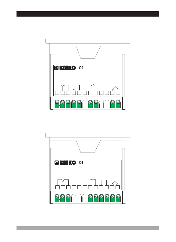
3.3 View of the Device Label
Device Label for J Type(0;800)scaled, with Thermocouple input , 230V Supply
Device Label for J Type(0;800)scaled , with 12V Supply Voltage Input and Relay
Voltage Input and Relay Output
CAT II
a
Y
P/N : ESM-3711-H - 5.05.0.1/00.00/1.0.0.0
OUTPUT
230 V ± 15%
2
50/60Hz - 1.5VA
L
3
41
V
N
5
10A@250V V
NO NCC
P/N : ESM-3711-H - 6.05.0.1/00.00/1.0.0.0
OUTPUT
10A@250V V
NO NCC
5
3
2
41
c
DIGITAL
INPUT
6 789101112
Output
DIGITAL
INPUT
6 7 8 9 10 11 12
W
c
W
12 V ± 15%
50/60Hz
1.5VA
L
N
-
+
( 0 to 800°C)
a
( 0 to 800°C)
J TypeTC
Scale
CAT II
J TypeTC
Scale
V
14

3.4 Supply Voltage Input Connection of the Device
Connection of Supply Voltage
Input
Y
Connection of Supply Voltage
Input
Note-2
Note-1
Power
Supply
Switch
External
Fuse
(1 A T)
a
9NL10
Note-2
External
Fuse
(1 A T)
a
4NL5
c
Supply Voltage
V
230 V (± 15%) 50/60 Hz or
V
115 V (± 15%) 50/60 Hz or
V
24 V (± 15%) 50/60 Hz or
W
24 V (-15%,+10%) 50/60 Hz
Make surethat thepower supply voltageis sameindicated on theinstrument.
Switch on the power supply only after that all the electrical connection have
been completed.
c
Supply voltage range must be determined in order. While installing the unit,
supply voltage range must be controlled and appropriate supply voltage must
be applied to the unit. Controlling prevents damages in unit and system and
possible accidentsas aresult of incorrectsupply voltage.
There is no power supply switch or fuse on the device. So a power supply
switch and a fuse must be added to the supply voltage input. Power supply
switch andfuse mustbe put toa placewhere user canreach easily.
c
Power supply switch must be two poled for seperating phase and neutral.
On/Off condition of power supply switch is very important in electrical
connection. On/Off condition of power supply switch must be signed for
preventing thewrong connection.
External fusemust beon phase connectionin supply input.
External fusemust beon (+) lineconnection in supply input.
Supply Voltage
12 V (± 15%) 50/60 HzW
Note-1: “L”is (+),“N” is (-)for 12V and
24V Supply Voltage
Z
Note-2: ExternalFuse isrecommended
V
Z
Note-1
Power
Supply
Switch
c
Z
15

3.5 Temperature Sensor Input Connection
3.5.1 TC (Thermocouple) Connection
TC
10
3.5.2 PTC Connection
PTC
1211
Connect the wires with the polarity as shown in the
figure left.
WHITERED
Always use compensation wire
corresponding to the thermocouple used. If
present, the shield must be connected to a
i
proper ground.
Input resistanceis greaterthan 10M W.
i
10
i
i
3.5.3 PT-100 and PT-1000 Connection
10
i
1211
Pay attention the cable colours of PTC probe while doing the PTC probe
connection.
Input resistanceis greaterthan 10M W.
PT-100
1211
Input resistanceis greaterthan 10M W.
10
PT-1000
1211
16
3.6 Galvanic Isolation Test Values of 711-HESM-3 Temperature Controller
2000 ( ESM-3 )
V For 711-H-5......
Supply Voltage
Input
V
500V ( For ESM- 711-H-3...... )
4
5
2000V V
2000V V
V
1
2
Relay Output
3
1
Optional SSR
2
Driver Output
2000V V
11
2000 V V
7
8
Output-1
Analog
Inputs
Digital
nputsI
3
Ground
2000V V
1
2
3
1
2
11
7
8
Galvanic IsolationTest Values for thedevices with12 V Supply voltageinput:W
Supply Voltage
Input
9
10
2000V V
1
Output-1
2
Relay Output
3
1
Optional SSR
2
Driver Output
Ground
2000V V
1
2
3
1
2
12
12
Analog
11
Inputs
7
Digital
8
Inputs
11
7
8
17

3.7 Output Connections
3.7.1 Relay Output Connection
Device
NC
3
C
2
1
NO
c
3.7.2 Output (SSR Driver Output) Connection
Fuses mustbe selectedaccording to theapplication.
A T Fuse10 V
Device
Last Control
Element
2
(SSR)
1
5V
Z
Max. 15mA
Max
Load
Load
c
c
Fuse
LN
LN
Fuses mustbe selectedaccording to theapplication.
c
18
4. Front Panel Definition and Accessing to the Menus
Led indication of SET value
changing mode
Led indication of
Output is Active
Cooking Time Active
and Temperature
Control Delay
Active Led
Heating Controller
Display Temperature
Value, Temperature
Set Value and
Parameters
Note-1: If increment or decrement button is pressed for 5 seconds continuously, increment and
decrement number become 10, if increment or decrement button is pressed for 10 seconds
continuously,increment and decrement numberbecome 100.
Note-1
It is used to
decrease the
value and silence
the buzzer
Led indication of
Programming Mode is
active
ESM - 3711-H
SV
PR
SET
°C
It is used to enter to the SET
value changing mode,
programming mode and used
as OK button.
Note-1
It is used to
increase the value
and access to the
parameter in
programming
mode.
Cooking Button
Cooking Time
(Timer) Value
Cooking ON/OFF
Button
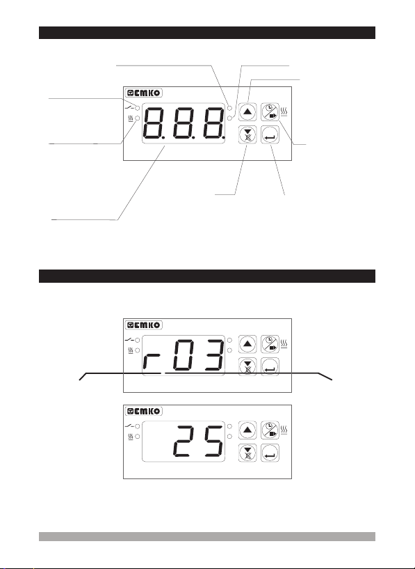
4.1 Observation of Software Revision on the Displays
When power is first applied to the temperature controller, software revision number is shown on
the displays.
ESM - 3711-H
SV
PR
SET
“ r” RevisionÞ
Heating Controller
Heating Controller
°C
SV
PR
°C
ESM - 3711-H
SET
Revision
number
Mai n Op era tion Scr een is shown
If there is an unexpected situation while opening the device, power off the
c
device andinform aqualified personnel.
19

4.2 Changing and Saving Set Value
Main Operation Screen
SV
PR
SET
When SET button is pressed, SV LED
lights on and SET value is shown on
°C
the display.
SET Value Screen
SV
PR
Change the SET value with increment
and decrement buttons.
°C
SET
SET Value Screen
SV
PR
°C
Press SET button for saving the
SET value
SET
Main Operation Screen
SV led lights off and main operation
screen is shown.
4.3 Changing and Saving Cooking Time (Timer) Parameter Value
Main Operation Screen
SV
PR
SET
When cooking button is pressed,
cooking time is shown and cooking time
active led starts to blink
°C
Cooking Time (Timer) Value Screen
SV
PR
SET
°C
Press Set button for saving the
cooking Time
If no operation is performed incooking Time enter mode and Set value enter mode
for 20seconds, deviceturns to mainoperation screenautomatically.
i
Cooking Time (Timer) Value Screen
Change the cooking time with increment
and decrement buttons
Main Operation Screen
Cooking time is saved, cooking time
active led lights off, main operation
screen is shown.
SV
PR
SET
°C
SV
PR
SET
°C
SV
PR
SET
°C
20

4.4 Programming Mode Parameter List
Hysteresis Parameterfor Output ( Default = 0)
From 0to 100°C for TC Type devices,
From 0to 100°C for PT-100 (-50°C ,400°C) and PT-1000(-50°C ,400°C) ,
From 0.0to 10.0°C for PT-100 (-19.9°C, 99.9°C)and PT-1000 (-19.9°C,99.9°C)
From 0to 20°C for PTC(-50°C, 150°C),
From 0.0to 10.0°C PTC (-19.9°C, 99.9°C)
In ON/OFF control algorithm, temperature
value is tried to keep equal to set value by
opening or closing the last control element.
ON/OFF controlled system, temperature
value oscillates continuously. Temperature
value’s oscillation period or amplitude
around set value changes according to
controlled system. For reducing oscillation
period of temperature value, a threshold
zone is formed below or around set value
and thiszone isnamed hysteresis.
Minimum SetValue Parameter( Default= Input Type Minimum Scale )
Set valuecan notbe lower thanthis value.
This parameter value can be adjusted from minimum value of device scale to
maximum setvalue parameter
Maximum SetValue Parameter( Default= Input Type Maximum Scale )
Set valuecan notbe greater thanthis value.
This parametervalue canbe adjusted fromminimum setvalue parameter to
maximum valueof thedevice scale
Process OffsetParameter ( Default= 0 )
From -100 to100°C forTC Typedevices,
From -100 to100°C forPT-100 (-50°C, 400°C) and PT-1000 (-50°C, 400°C),
From -10.0to 10.0°Cfor PT-100(-19.9°C, 99.9°C) andPT-1000 (-19.9°C,99.9°C),
From -20 to20°C forPTC (-50°C, 150°C),
From -10.0to 10.0°Cfor PTC (-19.9°C,99.9°C)
Temperature Control Delay at PowerOn
It canbe adjustedfrom 0 to99 minutes.
Cooking Time (Timer)Parameter
It can be adjusted from 1 to 999 minutes. When it is 1, can be observed by
pressing decrement buttonon the display. So Manual Controlis selected. In Manual
control, user can start and stop temperature controlling with cooking ON/OFF button
or .
cooking timestart/stop input
Selection of Temperature Control and Starting Cooking Time (Timer)
Parameter (Default =0 )
Temperature
Set
Temperature
Control Output
ON
OFF
( Default= 0)
( Default= 45)
HSt
Temperaturecontrol andcooking time (Timer) startsat poweron
Temperature control starts at power on. Cooking time (Timer) can be
started by pressing cooking ON/OFF button or when cooking time
start/stop inputis gettingclosed condition.
Temperature control and cooking time (Timer) can be started by pressing
cooking ON/OFF button or when cooking time start/stop input is getting
closed condition.
HSt
Time
Time
21

Cooking Time StartingConditions Parameter
This parametercan beobserved if cookingtime (Timer) is 1.³
Cooking time (Timer) is started with cooking ON/OFF button or when
cooking timestart/stop inputis getting closedcondition.
Cooking time (Timer) is started when temperature reaches to the process
set value after pressing cooking ON/OFF button or when cooking time
start/stop inputis gettingclosed condition.
TemperatureControlling Continuity Selection Parameter
Temperaturecontrolling can becontinues or stoppedaccording to theselection. This
parameter canbe observedif cooking time(Timer) is 1³
Continuous Operation : Temperature control starts after the temperature
control starting delay at power on is expired and continues. Ifbuzzer
function selection parameter Is 1or 4, at the end of the cooking time,
(Timer) internal buzzeroperates toindicate cooking timehas finished.
Interrupted Operation : Temperature control starts after temperature
control starting delay at power on is expired. Temperature control
can be stopped at the end of the cooking time (Timer) or by pressing
cooking ON/OFF button or when
open condition.
button is pressed again or when
closed conditionagain.
Temperature control does not start till cooking ON/OFF
( Default= 0)
( Default= 0)
cooking time start/stop input is getting
cooking time start/stop input is getting
TemperatureAlarm FunctionSelection Parameter (Default =0 )
TemperatureAlarm functionis inactive.
Absolute alarm is selected. If temperature is lower than and higher
than , thenalarm ison.
Relative alarm is selected. Alarm operates according to the set value. If
temperature is below ( Set - ) or above ( Set + ) , alarm
occurs.
Minimum Alarm Parameter
It canbe adjustedfrom minimum scaleof thedevice to maximumalarm value(AuH).
Maximum Alarm Parameter(Default =Input TypeMaximum Scale)
It canbe adjustedfrom minimum alarmvalue (AuL)to maximum scaleof thedevice.
Alarm DelayParameter (Default = 0)
If analarm occurs,delay can bedefined withthis parameter.It can beadjusted from0
To99 minutes.
Alarm DelayAfter PowerOn Parameter (Default =0)
This parameter defines the delay for the alarm is being active after power on. It can
be adjustedfrom 0to 99 minutes.
( Default= InputType MinimumScale )
Buzzer FunctionSelection Parameter( Default =1 )
Buzzer isinactive.
Buzzer isactive atthe end ofthe cookingtime.
Buzzer isactive ifan alarm occurs.
Buzzer isactive duringsensor failures.
Buzzer isactive atthe end ofthe cookingtime, alarm orsensor failures.
22
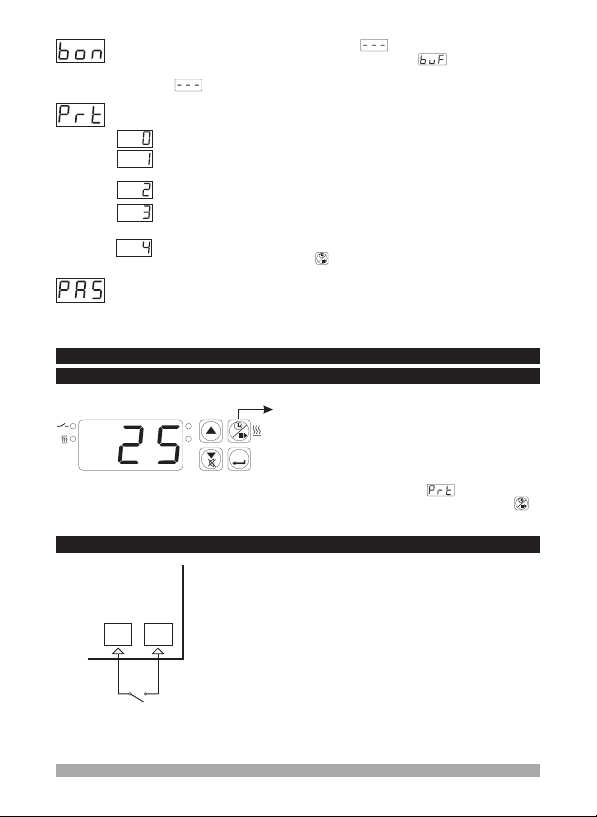
Buzzer isActive DuringThis Time
This parametercan beobserved if buzzerfunction selection is 1.
It canbe adjustedfrom 1 to99 minutes. When thisparameter is 1, if decrementbutton
is pressed, is observed. Thenbuzzer becomes active tillbuzzer silence button
( Default= )
³
Button ProtectionParameter (Default = 0)
There isno protection
Cooking time(Timer) can not be changed. Cooking ON/OFF operation is
not performed.
SET value cannot be changed
Cooking time (Timer) and set value can not be changed. Cooking ON/OFF
operation isnot performed.
Cooking time (Timer) and set value can not be changed. CookingON/OFF
operation isperformed when button is pressed.
Programming ModeAccessing Password
Password forentering tothe programming modeis definedwith this parameter.
It can be adjusted from 0 to 999. If it is 0, programming mode accessed without
entering password.
( Default= 0)
4.5 Cooking Time (Timer) ON/OFF Operation
4.5.1 Cooking Time (Timer) ON/OFF Operation with Cooking Button
Main Operation Screen
3 secs
In main operation screen, If cooking button is
SV
PR
°C
pressed for 3 seconds, then cooking time (Timer) is
started and cooking time active led becomes active.
While cooking time (Timer) continues if cooking
SET
button ispressed for 3seconds, cooking time(Timer)
is finishedand cookingtime active ledlights off.
If buttonprotection parameter = 4 cookingtime
(Timer) ON/OFF operationis performedwhen
button ispressed.
4.5.2 Cooking Time (Timer) ON/OFF Operation with Cooking Time Start/Stop Input
When K switch that is connected to the cooking time
start/stop input, getting closed condition, cooking
DIGITAL INPUT
78
time (Timer) is started and cooking time active led
becomes active. While cooking time (Timer)
continues if K switch getting open condition, cooking
time (Timer) is finished and cooking time active led
lights off.
K
23

4.6 Operation Graphics of ESM-3711-H Heating Controller
1- Whencooking time parameter 1, if selection oftemperature control and starting
the cooking time parameter = 0 ( Temperature control and cooking time starts at
power on)is selected;
01
( Continuous Operation)
Power
Cooking
Time
Active
Led
°C
Process
Hst
Set
Process
Output
=
Buzzer is
Active
=1
Temperature
Control is Active
³
Time
Cooking
Button starts
time
Time
Time
Time
Power
Cooking
Time
Active
Led
Process
Set
Process
Output
( Interrupted Operation )
°C
Hst
Control is Active
Temperature
=
Buzzer is
Active
=1
Time
Cooking
Button starts
time
Time
Time
Temperature
Control is Active
Time
2- Whencooking time parameter 1, if selection oftemperature control and starting
the cooking time parameter = 1 ( Temperature control starts at power on. Cooking
time (Timer) can be started by pressing cooking ON/OFF button or when
start/stop inputis gettingclosed condition)
01
( Continuous Operation) ( Interrupted Operation )
Power
Cooking
Time
Active
Led
= =
Cooking
Button starts
Buzzer is
time
=1 =1
°C
Process
Hst Hst
Set
Temperature
Process
Output
Control is Active
Active
³
Time
Cooking
Button starts
time
Time
Time
Time
is selected;
Power
Cooking
Time
Active
Led
°C
Process
Set
Process
Output
Cooking
Button starts
time
Temperature
Control is Active
cooking time
Buzzer is
Active
Temperature
Control is Active
Time
Cooking
Button starts
time
Time
Time
Time
24
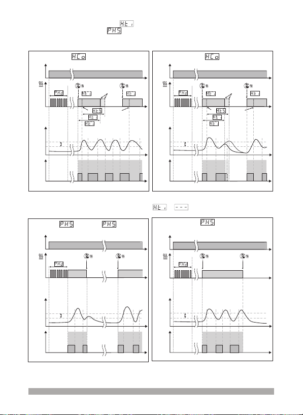
3- Whencooking time parameter 1, if selection oftemperature control and starting
the cookingtime parameter = 2 ( Temperature control andcooking time (Timer) can
be started by pressing cooking ON/OFF button or when
getting closedcondition)
( Continuous Operation) ( Interrupted Operation )
Power
Cooking
Time
Active
Led
is selected;
01
= =
Cooking
Button starts
Buzzer is
time
=1 =1
Active
³
Time
Cooking
Button starts
time
Time
Power
Cooking
Time
Active
Led
cooking time start/stop input is
Buzzer is
Active
Time
Cooking
Button starts
time
Time
Cooking
Button starts
time
°C
Process
Hst Hst
Set
Time
Time
Process
Output
Temperature
Control is Active
4- Manual Control : If cooking time (Timer)
0or 1
( Temperature control starts at power on )
Power
Cooking
Time
Active
Led
°C
Process
Hst
Set
Temperature
Process
Output
Control is Active
=
Cooking
Button stops
the temperature
control
=
Time
Cooking
Button starts
the temperature
control
Time
Time
Temperature
Control is Active
Time Time
°C
Process
Set
Process
Output
Temperature
Control is Active
Temperature
Control is Active
=
2
( Temperature control starts with cooking ON/OFF button or
Power
Cooking
Time
Active
Led
°C
Process
Hst
Set
Process
Output
=
Cooking
Button starts
the temperature
control
Temperature
Control is Active
Cooking
Button stops
the temperature
control
Time
Time
)when cooking time start/stop input is getting closed condition
Time
Time
Time
25
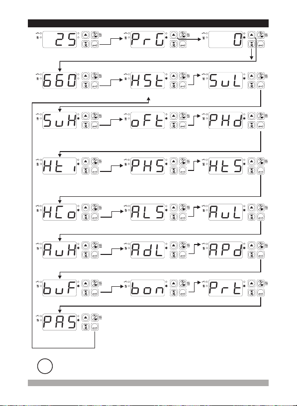
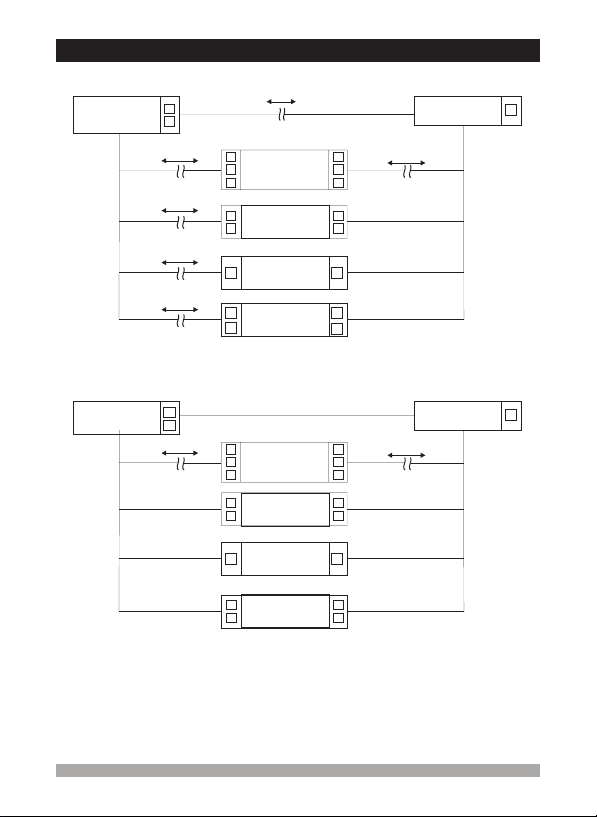
4.7 Easy Access Diagram of Programming Mode Parameters
SV
PR
Main Operation Screen
°C
Enter password with increment and decrement buttons
SV
PR
°C
Password
Entering Screen
Maximum Set Value
Press SET/OK button for
accessing parameters
SV
PR
°C
5 secs
SET
Programming Section
Entering Screen
SET
SET
Process Offset
Hysteresis
SV
PR
SET
°C
SV
PR
SET
°C
SV
PR
SET
°C
Password Entering
Screen
Minimum Set Value
Temperature Control
Delay at Power On
SV
PR
SET
°C
SV
PR
SET
°C
SV
PR
SET
°C
SV
PR
SET
Cooking Time (Timer)
Temperature Controlling
Continuity Selection
Maximum Alarm
Buzzer Function Selection
Programming Mode
Accessing Password
i
°C
SV
PR
°C
SV
PR
°C
SV
PR
°C
SV
PR
°C
If no operation is performed in programming mode for 20 seconds, device turns to
main operationscreen automatically.
Selection of Temperature Control
and Starting the Cooking Time
SET
Temperature Alarm
Function Selection
SET
Alarm Delay
SET
Buzzer is Active During this time
SET
SV
PR
SET
°C
SV
PR
°C
SV
PR
°C
SV
PR
°C
Cooking Time Starting
Conditions Parameter
SET
SET
Alarm Delay at Power On
SET
Minimum Alarm
Button Protection
SV
PR
SET
°C
SV
PR
SET
°C
SV
PR
SET
°C
SV
PR
SET
°C
26

4.8 Entering to the Programming Mode, Changing and Saving Parameters
Operation Screen
SV
PR
SET
°C
When SET button is pressed
for 5 seconds, “PR” led starts
to blink. If programming
section entering password is
different from 0, programming
section entering screen
is observed.
Note-1: If programming
section accessing
password is 0,
hysteresis screen
is observed instead of
programming screen
accessing password
Programming Section
Entering Screen
Press increment
button for accessing
to the password
SV
PR
SET
°C
SV
PR
SET
Password Entering Screen
Enter Programming Section
Accessing Password with
increment and decrement buttons.
Note-2: Parameters can be observed by pressing SET/OK button in password entering
screen withoutentering the programmingsection entering password. But parameterscan
not bechanged.
°C
Password Entering Screen
Press SET/OK button for
accessing to the parameters.
SV
PR
°C
Programming Screen
SV
PR
SET
°C
Hysteresis Parameter
Press increment button for accessing to the
parameter value. Press Set button for
accessing tothe nextparameter.
Hysteresis
Change the value with
increment and decrement
buttons.
SV
PR
°C
Programming Screen
SV
PR
SET
Hysteresis
Press Set button for saving
the parameter.
If no operation is performed in programming mode for 20 seconds, device turns to
main operationscreen automatically.
i
°C
Hysteresis Parameter
Press Set button for accessing
to the next parameter.
SV
PR
°C
SET
SET
SET
27

Programming Screen
SV
PR
SET
Minimum Set Value Parameter
Press increment button for accessing
to the parameter value. Press Set
button for accessing to the next
parameter.
Minimum Set Value
Press Set button for saving
the parameter.
°C
SV
PR
SET
°C
Other Programmingmode parameters canbe accessed
with the same method explained above, observed and
i
changed.
SV
PR
°C
Minimum Set Value
Change the value with
increment and decrement
buttons.
Programming Screen
SV
PR
Minimum Set Value Parameter
Press Set button for accessing
to the next parameter.
°C
SET
SET
If no operation is performed in programming mode for 20 seconds, device turns to
main operationscreen automatically.
i
28
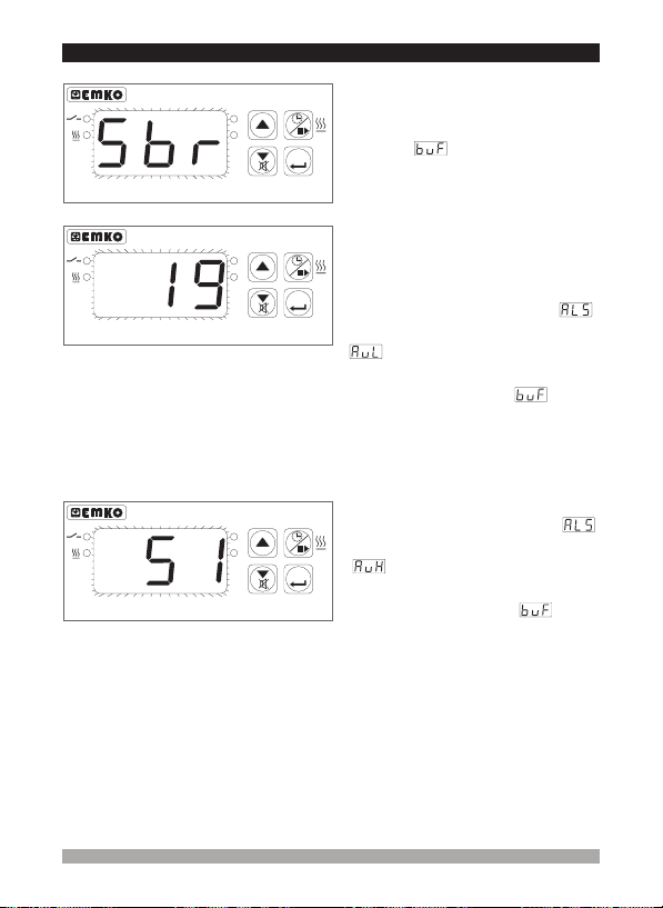
5. Failure Messages in ESM- Heating Controller3711-H
Heating Controller
Heating Controller
Heating Controller
SV
PR
°C
SV
PR
°C
SV
PR
°C
ESM - 3711-H
SET
ESM - 3711-H
SET
ESM - 3711-H
SET
1- Probe failure in analog inputs.
connection is wrong or there is no sensor
connection.
screen, if buzzer function selection
parameter is 3 or 4 , internal buzzer
starts tooperate.
2- Blinkingthe ScreenValue
If temperature higher than the alarm
parameters limit,value onthe screen startsto
blink
Example-1 :
If alarm function selection parameter
In programming section is 1(Absolute
alarm) and minimum alarm parameter
When temperature is less than 20
on the screen starts to blink. Also if buzzer
function selection parameter is 2 or 4
, then internal buzzer is on.
Example-2 :
If alarm function selection parameter
in programming section is 1 (Absolute
Alarm) and maximum alarm parameter
When temperature is above 50 °C, value
on the screen starts to blink. Also buzzer
function selection parameter is 2 or
4, then internal buzzer is on.
When this message is on the
Is 20 ;
is 50
Sensor
°C, value
29

6. Specifications
Device Type
Housing&Mounting
Protection Class
Weight
Environmental Ratings
Storage / Operating Temperature
Storage / Operating Humidity
Installation
Overvoltage Category
Pollution Degree
Operating Conditions
Supply Voltage and Power
Temperature Sensor Inputs
PTC Input Type
Thermocouple Input Types
Thermoresistance Input Type
Accuracy
Cold Junction Compensation
Sensor Break Protection
Sampling Cycle
Control Form
Relay Output
Optional SSR Output
Display
LED
Internal Buzzer
Approvals
: Heating Controler
: 77mm x 35mm x 62.5mm plastic housing for panel
Mounting. Panel cut-out is 71x29mm.
: NEMA 4X (IP65 at front, IP20 at rear).
: Approximately 0.20 Kg.
: Standard, indoor at an altitude of less than 2000 meters
with none condensing humidity.
oooo
: -40 C to +85 C / 0 C to +50 C
: 90 % max. (None condensing)
: Fixed installation
: II.
: II, office or workplace, none conductive pollution
: Continuous
: V (± 15%) 50/60 Hz. 1.5
V
230 VA
V (± 15%) 50/60 Hz. 1.5
V
115 VA
24V (± 15%) 50/60 Hz. 1.5
V
V (-%15, +%10) 50/60 Hz. 1.5
W
24 VA
V (± 15%) 50/60 Hz. 1.5
W
12 VA
: PTC, TC, RTD
: PTC (1000 @.25 °C )
: J, K (IEC584.1)(ITS90)
: PT-100, PT-1000 (IEC751)(ITS90)
: ±1 % of full scale for thermocouple and thermoresistance
: Automatically ± 0.1°C/1°C.
: Upscale
: 3 samples per second
:ON/OFF
: A@250V for resistive load
: Maximum 15 mA@5 V
: 14 mm Red 3 digits LED Display
: SV (Green) , Output Active (Red) , PR(Red) ,
: 83dB
: GOST-R,
W
10
(Electrical Life : 100.000 switching at full load)
Cooking Time Active (Red) 3 mm Led
³
V
VA
Z
30
 Loading...