

Page 1
ESM-9944-N / ESM-9945-N
COOKING CONTROLLERS
ESM-9944-N / ESM-9945-N Cook�ng Controllers
- 4 d�g�ts d�splay
- J type Thermocouple Input or
K type Thermocouple Input or
R type Thermocouple Input or
S type Thermocouple Input or
2 or 3 w�re PT 100 Input
- Adjustable Process Offset Value
- Programmable ON/OFF, P, PI, PD ve PID control types
- Adaptat�on of PID coeff�c�ents to the system by Auto Tune/Self Tune
- Work�ng t�me select�on �n m�nutes or seconds
- Vo�ced warn�ng v�a �nternal buzzer
- Cover sw�tch �nput
- Steam output (ESM-9945-N)
ESM-9944-N / ESM-9945-N cook�ng controllers are ma�nly used for Bakery
appl�cat�ons, fermantat�on cab�nets, ceram�cs and glass ovens, gra�n dr�er
cab�net, �ndustr�al fryer, �ncubators. Accurate and advanced controll�ng �s
performed w�th selectable ON-OFF, P, PI, PD ve PID, Self-Tune PID, AutoTune PID funct�ons.
SPECIFICATIONS
INPUT
Process Input: TC/RTD
Thermocouple (TC): J, K, R and S (IEC584.1)(ITS90)
Thermores�stance (RTD): 2 or 3 w�re Pt100 ( IEC 751) (ITS90)
Measurement Range: Please refer to parameter �n parameters sect�on.
Accuracy: ± 0.25% of scale for thermocouple and thermores�stance.
Cold Junct�on Compensat�on: Automat�cally ±0.1°C/1°C
L�ne Compensat�on: Max�mum 10 Ohm
Sensor Break Protect�on: Upscale
Sampl�ng Cycle: 0.1 second
CONTROL
Control Forms: ON/OFF, P, PI, PD veya PID (Control form can be
programmed by the user.)
OUTPUT
Temperature Control Output : Relay (7A@250VV at res�st�ve load) or opt�onal
SSR Dr�ver Output (Max�mum 10mA, 17VZ )
T�me Output : Relay (5A@250VV at res�st�ve load) or opt�onal SSR Dr�ver
Output (Max�mum 10mA, 17VZ )
Steam Output(ESM-9945) : Relay (5A@250VV at res�st�ve load) or opt�onal
SSR Dr�ver Output (Max�mum 10mA, 17VZ )
Bes�des these, there �s an �nternal buzzerfor vo�ced warn�ng.
SUPPLY VOLTAGE
230VV (±15%) 50/60Hz - 3VA
115VV (±15%) 50/60Hz - 3VA
24VV (±15%) 50/60Hz - 3VA
(Must be determ�ned �n order.)
DISPLAY
Temperature D�splay: 16 mm Red 4 d�g�ts LED D�splay
Led Ind�cators: O1 (Temperature Control Output Status LED), O2 (T�me Control
Output Status LED), Steam Output LED(ESM-9945-N), T�me Ind�cator,
Temperature Ind�cator, P(Programm�ng Mode LED),ºC, ºF LEDs
ENVIRONMENTAL RATINGS and PHYSICAL SPECIFICATIONS
Operat�ng Temperature: 0...50ºC
Hum�d�ty : 0-90%RH (none condens�ng)
Protect�on Class: IP65 at front , IP20 at rear
We�ght: 370 gr.
D�mens�on: 96 x 96 mm, Depth: 100 mm
Panel CutOut: 92 x 92 mm
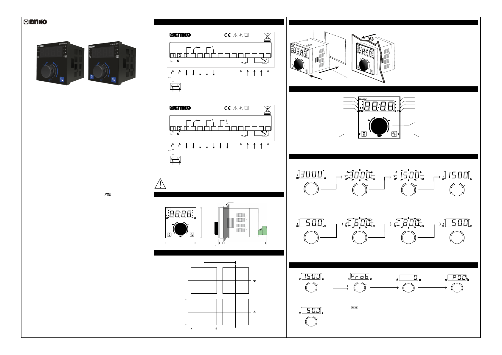
Electr�cal W�r�ngs
ESM-9944-N
7A@250VV 5A@250VV
NCCNO
CNO
5
6 7 8 9
4
Output-1
Output-2
L
N
1A T
Supply
Voltage
Sw�tch
Supply
Voltage
Sw�tch
S�gorta
1A T
S�gorta
(Temperature Control
Output)
Supply
Voltage
ESM-9945-N
7A@250VV 5A@250VV5A@250VV
Output-1
L
N
(Temperature Control
Output)
Supply
Voltage
To reduce the effect of electr�cal no�se on dev�ce, low voltage l�ne (espec�ally sensor
�nput cables) w�r�ng must be separately from h�gh current and voltage l�ne. If
poss�ble, use sh�elded cable abd sh�eld must be connected to ground only one s�de.
O1
4
O1
O2
(T�me End
Output)
NCCNO
5
6 7 8 9
Output-2
O2
(T�me End
Output)
CNO CNO
Output-3
O3
(Steam
Output)
10
10
CAT II
11 121314
D�g�tal Input
Temperature
Cover
Sensor Input
Sw�tch
CAT II
11 121314
D�g�tal Input
Temperature
Cover
Sensor Input
Sw�tch
D�mens�ons
ESM-9945-N
O1
O2
°C
°F
P
Max�mum 15 mm / 0.59 �nch
+ -
SET
96 mm / 3.78 �nch
96 mm / 3.78 �nch
11.5 1mm / 0.45 �nch
84 mm / 3.31 �nch
Panel Cut-out
129 mm / 5.08 �nch(m�n)
92 mm / 3.62 �nch(m�n)
92 mm / 3.62 �nch(m�n)
PT-100
PT-100
129 mm / 5.08 �nch(m�n)
Panel Mount�ng
1
4
5
15
TC
3
2
1- Before mount�ng the dev�ce �n your panel, make
sure that the cutouts �s of the r�ght s�ze.
2- Check front panel gasket pos�t�on.
3- Insert the dev�ce through the cutout. If the
mount�ng clamps are on the un�t, put out them before
�nsert�ng the un�t to the panel.
4- Insert the mount�ng clamps to the two of
des�gnated holes that located on four s�des of dev�ce.
5- Drag the mount�ng clamps �n d�rect�on 5 unt�l the
dev�ce completely �mmob�le w�th�n the panel.
6- In order to remove dev�ce push on the mount�ng
clamp as shown w�th arrow 6 and pull back.
Front Panel Def�n�t�on
Temperature Control Output Status
T�me End Output Status
Steam Output Status(ESM9945N)
T�me �nd�cator
O1
O2
ESM-9945-N
+ -
15
TC
Steam Start-Stop Button
(ESM9945N)
SET
Temperature Un�t Ind�cator
Temperature Un�t Ind�cator
°C
Programm�ng Mode Ind�cator
°F
Temperature Ind�cator
P
Encoder Button
T�me Start-Stop Button
If cooking time is not active, starts
cooking time. If cooking time is
started, cooking time is cancelled
and buzzer is silenced.
Access and Change Set Value
Time Set Value
Ma�n Screen
O1
O2
++
+
Press encoder button
to observe the set value.
°C
°F
P
SET
Temperature Set Value
O1
O2
++
+
Press encoder button
to observe the set value.
°C
°F
P
Note : If no operat�on for 10 seconds, dev�ce automat�cally ex�ts from Set Value Screen w�thout sav�ng the value.
Set Value Screen
O1
O2
++
+
SET
Turn left encoder button
to decrease or turn right
to increase the set value.
Set Value Screen
O1
O2
++
+
Turn left encoder button
to decrease or turn r�ght
to �ncrease the set value.
Set Value Screen
°C
°F
P
°C
°F
P
O1
O2
++
+
Press encoder button
to save new set value
and return main screen.
Set Value Screen
O1
O2
++
+
Press encoder button
to save new set value
and return ma�n screen.
°C
°F
SET
°C
°F
P
P
Ma�n Screen
O1
O2
++
+
Ma�n ScreenMa�n Screen
O1
O2
++
+
°C
°F
P
SET
ESD-9950-N
°C
°F
P
SET
Access the Parameters
Ma�n Screen
O1
O2
+
Press encoder
button dur�ng 10 seconds.
Ma�n Screen
O1
O2
+
Press encoder
button dur�ng 10 seconds.
°C
°F
P
++
SET
°C
°F
P
++
SET
O1
O2
+
If no pr�vacy lock �dent�f�cat�on
Parameters Screen w�ll be
observed. If pr�vacy lock �s
�dent�f�ed, w�ll be observed.
Press encoder button to access
Password Screen.
°C
°F
P
++
SET
Password Screen
O1
O2
+
Enter the password using
encoder button. Turn left
encoder button to decrease or
turn right to increase value.
Approve password using
encoder button.
°C
°F
P
++
Instruct�on Manual. ENG ESM-994X-N 01 V02 02/18
Parameters Screen
O1
O2
+
If Parameters Screen is
active, "P" led blinks. To
observe previous parameter,
turn encoder button left. To
observe next parameter, turn
encoder button right. Press
encoder button to observe
parameter value.
°C
°F
P
++
Page 2
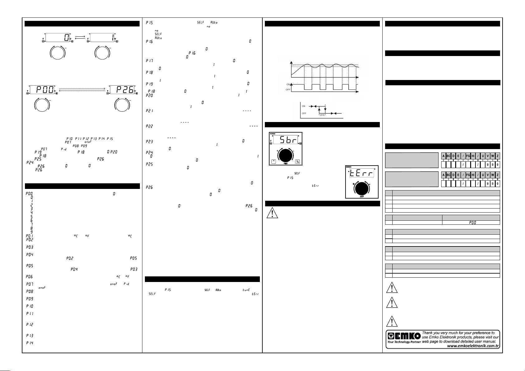
Access, Change and Record the Parameter Values
Parameter Values Screen
O1
O2
++
+
SET
To increase parameter
value, turn encoder button
right. Press encoder button
to save.
Parameters Screen
O1
O2
++
+
Turn encoder button
left to observe
previous parameter or
turn right to observe
next parameter.
Note1: PID control parameters ( , , , , , ) are not seen when
output control type parameter ( ) �s set as .
Note2: ON/OFF control parameters ( , ) are not seen when output control type
parameter ( ) �s set as .
Note3: parameter �s not seen when parameter set as . parameter can be
seen after parameter.
Note4: parameter �s not seen �n ESM9944N dev�ce. parameter can be seen after
parameter.
Note5: If �s d�fferent from and user enters on password screen, parameter values
except are observed but can not be changed.
Note6: If no operat�on for 20 seconds on Parameters Screen, dev�ce automat�cally returns
Ma�n Screen .
°C
°F
P
SET
Parameter Values Screen
O1
°C
°F
O2
P
++
+
To decrease parameter
value, turn encoder button
left. Press encoder button
to save.
°C
°F
P
SET
Parameters Screen
O1
O2
++
+
SET
Turn encoder button
left to observe
previous parameter or
turn right to observe
next parameter.
°C
°F
P
Parameters Descr�pt�ons
: Process �nput type select�on parameter. (Default: )
J type (Fe,Cu,N�) Thermocouple; -200ºC,900ºC ; -328ºF,1652ºF
J type (Fe,Cu,N�) Thermocouple; -199.9ºC,900.0ºC ; -199.9ºF,999.9ºF
K type (N�,Cr,N�) Thermocouple; -200ºC,1300ºC ; -328ºF,2372ºF
K type (N�,Cr,N�) Thermocouple; -199.9ºC,999.9ºC ; -199.9ºF,999.9ºF
R type (Pt13%RhPt) Thermocouple; 0ºC,1700ºC ; 32ºF,3092ºF
R t�p� (Pt13%RhPt) Thermocouple; 0.0ºC,999.9ºC ; 32.0ºF,999.9ºF
S t�p� (Pt10%RhPt) Thermocouple; 0ºC,1700ºC ; 32ºF,3092ºF
S t�p� (Pt10%RhPt) Thermocouple; 0.0ºC,999.9ºC ; 32.0ºF,999.9ºF
PT100 Thermores�stance; -200ºC,650ºC ; -328ºF,1202ºF
PT100 Thermores�stance; -199.9ºC,650.0ºC ; -199.9ºF,999.9ºF
: Un�t select�on parameter. or can be chosen. (Default: )
: Operat�on scale m�n�mum(Low L�m�t) value. It changes accord�ng to
the process �nput type and scale. (Default: -200)
: Operat�on scale max�mum(H�gh L�m�t) value. It changes accord�ng to
the process �nput type and scale. (Default: 900)
: Process set value low l�m�t parameter. It can be adjusted between
Operat�on Scale M�n�mum( ) and Process Set Value H�gh L�m�t( ).
(Default:-200)
: Process set value h�gh l�m�t parameter. It can be adjusted between
Process Set Value Low L�m�t( ) and Operat�on Scale Max�mum( )
and (Default: 900)
: Process offset value. It can be adjusted as a degree( or ), from
-10% of scale to 10% of scale.It �s added to the process value. (Default: 0)
: Output control type parameter. It can be selected or .
(Default: )
: Hysteres�s value. It can be adjusted from 1º(po�nt representat�on:
0.1º) to 20º. (Default: 3)
: M�n�mum ON/OFF control output t�me parameter. It can be adjusted
from 0 to 60 seconds. (SSR Default: 0 ; Relay Default: 5)
: Proport�onal band (P). It can be adjusted from %1.0 to %100.0.
(Default: 10.0)
: Output Control Per�od. If control output �s SSR, It can be adjusted
from 0.5 to 150.0 seconds. If control output �s Relay, It can be adjusted 60.0
to 150.0 seconds. (SSR Default: 10.0 ; Relay Default: 60.0)
: Proport�onal Offset value. Th�s parameter �s used for sh�ft�ng the
proport�onal band. It can be adjusted from (-Operat�on Scale Max�mum /2)
to (Operat�on Scale Max�mum /2). (Default: 0)
: Integral T�me. It can be adjusted from 0 to 3600 seconds.
(Default: 100)
: Der�vat�ve T�me. It can be adjusted from 0.0 to 999.9 seconds.
(Default: 25.0)
: If tune parameter �s set to or , dev�ce starts to calculate
PID parameters automat�cally. (Default: )
: Dev�ce does not calculate PID parameters.
: Step Response Tun�ng operat�on.
: L�m�t Cycle Tun�ng operat�on.
:Temperature - T�me d�splay form. If parameter value set as ,only
Temperature or T�me value �s d�splayed accord�ng to selected page. If
parameter value set as d�fferent from , Temperature and T�me value �s
d�splayed alternately dur�ng parameter value. It can be adjusted from
0 to 99 seconds. (Default: )
: T�mer d�splayed form. If parameter value set as , t�mer form �s
M�nute-Second. If parameter value set as , t�mer form �s Hour-M�nute.
(Default: )
: T�mer counts d�rect�on parameter. If the parameter set as , t�mer
counts downt-to-up. If the parameter set as , t�mer counts up-to-down.
(Default: )
: T�mer count�ng method parameter. If the parameter set as , t�mer
counts act�ve t�me. If the parameter set as , t�mer counts set t�me.
If parameter set as , th�s parameter �s not seen. (Default: )
: T�mer Relay Pos�t�on Parameter. If the parameter �s , T�mer relay
becomes act�ve pos�t�on w�th the t�me start and becomes pass�ve at the
end of the t�me. If the parameter �s , then t�me relay becomes act�ve at
the end of the t�me. (Default: )
: Relay act�ve t�me parameter. If parameter value set as then
T�me End Output w�ll be act�ve cont�nously. If value set as a d�fferent
value(from 1 to 9999 seconds), T�me End Output w�ll be act�ve dur�ng the
entered t�me. (Default: )
: Buzzer act�ve t�me parameter. If parameter value set as ,
Buzzer w�ll be act�ve cont�nously. If parameter value set as a d�fferent
value (from 1 to 9999 seconds), Buzzer w�ll be act�ve dur�ng the entered
t�me. (Default: )
: D�g�tal �nput c�rcu�t parameter. If the parameter set as , c�rcu�t �s
Normally Open (NO). If the parameter set as , c�rcu�t �s Normally Closed
(NC). (Default: )
: Type of command when d�g�tal �nput act�vated. If the parameter set
as , t�mer stops count�ng and resets t�me. If the parameter set as ,
t�mer pauses count�ng. (Default: )
: Steam durat�on parameter (ESM9945N). If the Steam Durat�on
Parameter �s selected as then the steam output w�l be on dur�ng the
Steam button �s pressed. If the parameter value set as a d�fferent value
(from 1 to 9999 seconds), after press�ng the steam button, output w�ll be
on dur�ng the Steam Durat�on Parameter value. If Steam button �s
pressed when steam output �s on, steam output w�ll be off. (Default: )
: Password for access�ng to the parameters sect�on. It can be
adjusted from 0 to 9999. If parameter value �s , password screen �s not
seen. If parameter value �s d�fferent from and ;
-If user enters d�fferent value from saved value, dev�ce w�ll return to
ma�n screen automat�cally.
-If user enters , all parameters can be observed except .
But dev�ce does not allow to do any changes �n parameters. (Default: )
Tune Operat�on
Start�ng the Tune operat�on
1- Enter the parameter and select or . Observe that bl�nks.
(If �s selected and start cond�t�ons are not okay for Tune operat�on,
bl�nks dur�ng 10 seconds.)
2- Dev�ce calculates PID control coeff�c�ents and sets the process value to
wanted value.
Cancell�ng tune operat�on:
1- If sensor breaks;
2-If tune operat�on can not be completed �n 8 hours;
3-Wh�le tune operat�on �s runn�ng, �f process value becomes greater than
process set value;
4-Wh�le tune operat�on �s runn�ng, �f user changes the process set value;
5-Wh�le tune operat�on �s runn�ng, �f user changes the parameter �n menu;
Then tune operat�on �s canceled and dev�ce cont�nues to run w�th former PID
parameters w�thout chang�ng PID parameters.
Adjustment of Hysteres�s Value for ON/OFF Control
In ON/OFF control algor�thm, temperature value �s tr�ed to keep equal to set
value by open�ng or clos�ng com pletely last control element. ON/OFF controlled
system, temperature value osc�llates cont�nuously. Temperature value’s
osc�llat�on per�od or ampl�tude around set value changes accord�ng to controlled
system. For reduc�ng osc�llat�on per�od of temperature value, a threshold zone
�s formed below or around set val ue and th�s zone �s named hysteres�s. Act�on
of control output �s descr�bed w�th f�gures below.
Temperature
Temperature
Set Value
Hysteresis
Temperature
Control Output
Temperature
Control Output
Temperature
Set Value
ON/OFF
Conrol Form
with
Hysteresis
Temperature
Time
Time
Error Messages
ESM-9945-N
O1
O2
+ -
Tune fa�lure. If �s selected �n PID Tune
Parameter( ) and start cond�t�ons are not
okay for Tune operat�on, the temperature value
�s d�splayed alternately w�th message on
d�splay dur�ng 10 seconds.
°C
°F
P
Sensor fa�lure �n analog �nput. If there �s no
sensor connect�on or the value that �s read from
the analog �nput goes out of the dev�ce scale,
warn�ng �s observed.
SET
O1
O2
ESD-9950-N
+ -
SET
Installat�on
Before beg�nn�ng �nstallat�on of th�s product, please read
the �nstruct�on manual and warn�ngs below carefully.
In package,
-One piece unit
-Two pieces mounting clamp
-One piece instruciton manual
A visual inspection of this product for possible damage occured
during shipment is recommended before installation. It is your
responsibility to ensure that qualified mechanical and electrical
technicians install this product.
If there is danger of serious accident resulting from a failure or
defect in this unit, power off the system and the electric al
connection of the device from the system.
The unit is normally supplied without a power switch or a fuse.
Use power switch and fuse as required.
Be sure to use the rated power supply voltage to protect the unit
against damage and to prevent failure.
Keep the power off until all of the wiring is completed so that
electric shock and trouble with the unit can be prevented.
Never attempt to disassemble, modify or repair this unit.
Tampering with the unit may results in malfunction, electric shock
or fire.
Do not use the unit in combustible or explosive gaseous
atmospheres. During the equipment is put in hole on the metal
panel while mechanical installation some metal burrs can cause
injury on hands, you must be careful.
Montage of the product on a system must be done with it's
mounting clamp. Do not do the montage of the device with
inappropriate mounting clamp. Be sure that device will not fall
while doing the montage.
It is your responsibility if this equipment is used in a manner not
specified in this instruction manual.
Warranty
EMKO Elektronik warrants that the equipment delivered is free from defects
in material and workmanship. This warranty is provided for a period of two
years. The warranty period starts from the delivery date.
This warranty is in force if duty and responsibilities which are
determined in warranty document and instruct on manual performs by the
customer completely.
Ma�ntenance
Repairs should only be performed by trained and specialized personnel. Cut
power to the device before accessing internal parts. Do not clean the case
with hydrocarbon-based solvents (Petrol, Trichlorethylene etc.). Use of
these solvents can reduce the mechanical reliability of the device. Use a
cloth dampened in ethyl alcohol or water to clean the external plastic
case.
Other Informat�ons
Manufacturer Informat�on:
a
Emko Elektron�k Sanay� ve T�caret A.Ş.
Dem�rtaş Organ�ze Sanay� Bölges� Karanf�l Sk. No:6 16369
BURSA/TURKEY
a
Phone : +90 224 261 1900
Fax : +90 224 261 1912
a
Repa�r and Ma�ntenance Serv�ce Informat�on:
a
Emko Elektron�k Sanay� ve T�caret A.Ş.
Dem�rtaş Organ�ze Sanay� Bölges� Karanf�l Sk. No:6 16369
Bakım
BURSA/TURKEY
a
Phone : +90 224 261 1900
Fax : +90 224 261 1912
Order�ng Informat�ons
ESM-9944-N(96x96 DIN 1/4)
°C
°F
P
S
ESM-9945-N(96x96 DIN 1/4)
Supply Voltage
A
24VV (±%15) 50/60Hz
3
115VV (±%15) 50/60Hz
4
230VV (±%15) 50/60Hz
5
9
Customer
Input Type
BC
Conf�gurable20
Output-1 (Temperature Control Output)
E
Relay Output (7A@250VV at Res�st�ve Load) (NO,NC,C)
1
SSR Dr�ver Output (Max. 10mA, 17VZ)
2
Output-2 (T�me Output)
FG
Relay Output (5A@250VV at Res�st�ve Load) (NO,C)
01
SSR Dr�ver Output (Max. 10mA, 17VZ)
02
Output-3 (Steam Output) (ESM-9945-N)
HI
Relay Output (5A@250VV at Res�st�ve Load) (NO,C)
01
SSR Dr�ver Output (Max. 10mA, 17VZ)
02
Before comm�ss�on�ng the dev�ce, parameters must be set �n
accordance w�th des�red use. Incomplete or �ncorrect conf�gurat�on
can cause dangerous st�uat�ons.
Because of l�m�ted mechan�cal l�fe of relay output contact, SSR output
�s recommended wh�ch the dev�ce use PID control algor�tm. The
dev�ce w�th ON/OFF control algor�tm, hysteres�s parameter must be
set a su�table value for your system, to avo�d too much relay sw�tch�ng.
V → Vac,
Z → Vdc,
W → Vdc or Vac can be appl�ed.
20
20
Scale
See Parameters ( )
00
0
0
1
1
 Loading...