

Page 1
ON/OFF TEMPERATURE CONTROL UNIT
Eco
Eco LITE, On/Off Temperature Control Un�t
- 3 d�g�t process (PV) and 4 d�g�t set (SV) d�splay
- Process �nput (TC,RTD)
- ON/OFF control form
- Selectable heat�ng and cool�ng funct�on
- Operat�ng type select�on w�th hysteres�s
- Adjustment of temperature offset value
- M�n�mum pull�ng t�me adjustment for control outputs
- Password protect�on for programm�ng mode
Eco ser�es temperature controllers are des�gned for measur�ng and
controll�ng temperature. They can be used �n many appl�cat�ons w�th
the�r TC and RTD temperature measurement �nput, On/Off control form
and heat�ng and cool�ng select�on.
They are ma�nly used �n glass, plast�c, petro-chem�stry, text�le,
automot�ve and mach�ne product�on �ndustr�es.
SPECIFICATIONS
Process Input: TC, RTD
Thermocouple (TC): J, K, R, S, T and L (IEC584.1)(ITS90)
Termores�stance (RTD): Cu-50 and PT-100 (IEC751)(ITS90)
Measurement Range: Please refer to process �nput type select�on �n
process menu parameters sect�on.
Accuracy:
Thermocouple (TC):( ± 0.25% of full scale or ± 3ºC, wh�ch one �s
greater) ±1 d�g�t max.
Thermores�stance (RTD):( ± 0.25% of full scale or ± 2ºC, wh�ch one �s
greater) ±1 d�g�t max.
Cold Junct�on Compensat�on: Automat�cally ±0.1°C/1°C
L�ne Compensat�on: Max�mum 10 Ohm
Sensor Break Protect�on: Upscale
Sampl�ng Cycle: 0.1 second
Input F�lter: Programmable
Control Form: ON/OFF
ON/OFF Hysteres�s: It can be conf�gured for two control outputs
OUTPUT
Process Output - 1: Relay (5A@250VV at res�st�ve load)
Process Output - 2: Relay (5A@250VVat res�st�ve load)
SUPPLY VOLTAGE (It must be determ�ned �n order)
230VV (±15%) 50/60Hz - 2VA
115VV (±15%) 50/60Hz - 2VA
100-240VV 50/60Hz - 2VA
24VV(±%15) 50/60Hz - 2VA
24VW (±%15) 50/60Hz - 2VA
10...30VZ - 2W
DISPLAY
Process D�splay: 16 mm Red 3 d�g�t LED D�splay
Set Value D�splay: 9 mm Orange 4 d�g�t LED D�splay
Led Ind�cators: PO1 (Process Output-1 Status Led), PO2 (Process
Output-2 Status Led), ºC, ºF LEDs
ENVIRONMENTAL RATINGS and PHYSICAL SPECIFICATIONS
Operat�ng Temperature: 0...50ºC
Hum�d�ty: 0-90%RH (none condens�ng)
Protect�on Class: IP65 at front, IP20 at rear
We�ght: 150 gr.
D�mens�on: 48 x 48 mm, Depth: 86,5 mm
Panel CutOut: 46 x 46 mm
LITE
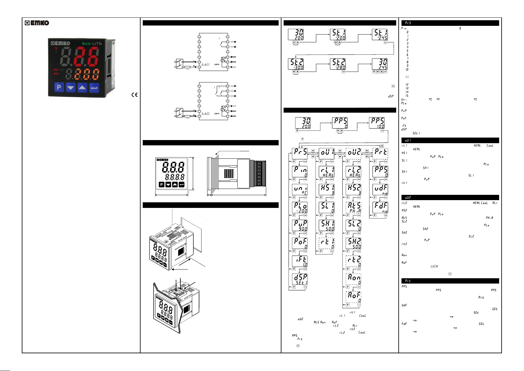
Electr�cal W�r�ngs
The Dev�ce w�th One Relay:
Supply
Voltage
Supply
Sw�tch
1A T
Fuse
1
2
3
4
5
N
6
L
7
Eco
LITE
8
NO
9
PO1
(Process Output 1)
C
5A@250V
10
11
12
Process
13
Input
TC
PT-100
14
The Dev�ce w�th Two Relays:
NO
1
2
5A@250V
Eco
5A@250V
LITE
3
4
5
N
Supply
Voltage
Supply
Sw�tch
To reduce the effect of electr�cal no�se on dev�ce, low voltage l�ne (espec�ally sensor
�nput cable) w�r�ng must be separetely from h�gh current and voltage l�ne. If poss�ble,
use sh�elded cable and sh�eld must be connected to ground only one s�de.
c
1A T
Fuse
6
L
7
D�mens�ons
Max�mum 9 mm / 0.35 �nch
Eco
°C
°F
PO1
PO2
/
LITE
AL1
48 mm / 1.89 �nch
48 mm / 1.89 �nch
6 mm / 0.24 �nch
Panel Mount�ng
1
°C
°F
Eco
LITE
PO1
AL1
PO2
/
3
2
4
5
6
°C
°F
Eco
LITE
PO1
AL1
PO2
/
1- Before mount�ng the dev�ce �n your
panel, make sure that the cutout �s of
the r�ght s�ze.
2- Check front panel gasket pos�t�on.
3- Insert the dev�ce through the cutout.
If the mount�ng clamps are on the un�t,
put out them before �nsert�ng the un�t to
the panel.
4- Insert the mount�ng clamps to the two
of des�gnated holes that located four
s�des of dev�ce.
5- Drag the mount�ng clamps �n
d�rect�on 5 unt�l the dev�ce completely
�mmob�le w�th�n the panel.
6- In order to remove dev�ce push on
the mount�ng clamp as shown w�th
arrow 6 and pull back.
PO2 / AL1
8
(Process Output 2 or
Alarm Output 1)
NO
9
PO1
(Process Output 1)
C
10
11
12
Process
13
Input
TC
PT-100
14
80,52 mm / 3.17 �nch
Access and Change Set Values
Ma�n Screen
°C
°F
PO1
AL1
PO2
/
AL2
Press �ncrement or decrement
button to change Set1 value.
°C
°F
PO1
AL1
PO2
/ PO2
AL2
Press �ncrement or decrement
button to change Set2 value.
Note1: User can ex�t from set value sect�on w �thout sav� ng the values by press�ng
button. If no operat�on for 120 seconds, dev�ce automat�cally ex�ts from Set Value
sect�on.
Note2: D�splayed set value at ma�n screen could be changed accord�ng to
parameter
Note3: Set values can be adjusted between Set Value Low and H�gh L�m�ts.
Easy Access D�agram For Program Parameters
Ma�n Screen
°C
°F
PO1
AL1
PO2
/
AL2
To enter program menu
press button
°C
°F
PO1
AL1
PO2
/
AL2
°C
°F
PO1
AL1
PO2
/
AL2
°C
°F
PO1
AL1
PO2
/
AL2
°C
°F
PO1
AL1
PO2
/
AL2
°C
°F
PO1
AL1
PO2
/
AL2
°C
°F
PO1
AL1
PO2
/
AL2
°C
°F
PO1
AL1
PO2
/
AL2
°C
°F
PO1
AL1
PO2
/
AL2
*1 - M�n�mum pull�ng t�me parameter for Output-1( ) �s not seen unless operat�on
type select�on for output-1 parameter( ) �s set as .
*2 - Out-2( ) parameters are not seen on dev�ces w�th one relay.
*3 - Alarm parameters( , and ) are not seen unless operat�on type
select�on for output-2 parameter( ) �s set as .
*4 - M�n�mum pull�ng t�me parameter for Output-2( ) �s not seen unless operat�on
type select�on for output-2 parameter( ) �s set as .
*5 - If �s d�fferent from 0 and user enters to program menu w�thout enter�ng the
password menu �s not seen.
Note: User can ex�t from any parameter screen w�thout sav�ng the values by
press�ng button. If no operat�on for 120 seconds, dev�ce automat�cally return to
the ma�n screen.
°C
°F
PO1
AL1
PO2
/ PO2
AL2
Press Enter button to save new
Set1 value and open Set2 screen.
°C
°F
PO1
AL1
/
AL2
Press Enter button to save new
Set2 value and return ma�n screen.
°C
°F
PO1
AL1
/
AL2
Enter Password w�th
�ncrement or decrement buttons.
°C
°F
PO1
AL1
PO2
/
AL2
°C
°F
PO1
AL1
PO2
/ PO2
AL2
°C
°F
PO1
AL1
PO2
/ PO2
AL2
°C
°F
PO1
AL1
PO2
/
AL2
°C
°F
PO1
AL1
PO2
/
AL2
°C
°F
PO1
AL1
PO2
/
AL2
°C
°F
PO1
AL1
/
AL2
°C
°F
PO1
AL1
/
AL2
°C
°F
PO1
AL1
/
AL2
°C
°F
PO1
AL1
/
AL2
°C
°F
PO1
AL1
/
AL2
°C
*1
°F
PO1
AL1
/
AL2
°C
°F
PO1
AL1
/
AL2
°C
°F
PO1
AL1
/
AL2
°C
°F
PO1
AL1
/
AL2
Password Screen
PO2
PO2
PO2
PO2
PO2
PO2
PO2
°C
°F
PO1
AL1
PO2
/PO2
AL2
Approve password
w�th Enter button
*2
*3
*4
*3
*3
°C
°F
PO1
AL1
/
AL2
Ma�n Screen
°C
°F
PO1
AL1
PO2
/
AL2
°C
°F
PO1
AL1
PO2
/
AL2
°C
°F
PO1
AL1
PO2
/
AL2
°C
°F
PO1
AL1
PO2
/
AL2
°C
°F
PO1
AL1
PO2
/
AL2
*5
: Process Menu Parameters
: Process �nput type select�on. (Default: )
: J type (Fe,Cu,N�) Thermocouple , -199ºC,900ºC ; -199ºF,999ºF
: J type (Fe,Cu,N�) Thermocouple , -19.9ºC,99.9ºC ; -19.9ºF,99.9ºF
: K type (N�,Cr,N�) Thermocouple , -199ºC,999ºC ; -199ºF,999ºF
: K type (N�,Cr,N�) Thermocouple , -19.9ºC,99.9ºC ; -19.9ºF,99.9ºF
: R type (Pt13%RhPt) Thermocouple , 0ºC,999ºC ; 32ºF,999ºF
: R type (Pt13%RhPt) Thermocouple , 0.0ºC,99.9ºC ; 32.0ºF,99.9ºF
: S type (Pt10%RhPt) Thermocouple , 0ºC,999ºC ; 32ºF,999ºF
: S type (Pt10%RhPt) Thermocouple , 0.0ºC,99.9ºC ; 32.0ºF,99.9ºF
: T type (Cu,Cu,N�) Thermocouple , -199ºC,400ºC ; -199ºF,752ºF
: T type (Cu,Cu,N�) Thermocouple , -19.9ºC,99.9ºC ; -19.9ºF,99.9
: L type (N�,Cr,Co / N�,Fe,Mn,Cu) Thermocouple , -150ºC,800ºC ;
-199ºF,999ºF
: L type (N�,Cr,Co / N�,Fe,Mn,Cu) Thermocouple , -19.9ºC,99.9ºC ;
-19.9ºF,99.9ºF
: Cu-50 , -199ºC,200ºC ; -199ºF,392ºF
: Cu-50 , -19.9ºC,99.9ºC ; -19.9ºF,99.9ºF
: Pt-100 , -199ºC,650ºC ; -199ºF,999ºF
: Pt-100 , -19.9ºC,99.9ºC ; -19.9ºF,99.9ºF
: Un�t Select�on. or can be chosen. (Default: )
: Operat�on Scale m�n�mum (Low L�m�t) value. It changes accord�ng
to the process �nput type and scale. (Default: -199)
: Operat�on Scale max�mum (H�gh L�m�t) value. It changes accord�ng
to the process �nput type and scale. (Default: 900)
: D�splay offset for process value. It can be adjusted from -10% of
scale to 10% ofscale. It �s added to the process d�splay value. (Default: 0)
: Def�ne f�lter t�me(sec) for d�splayed value. (Default: 1.0)
: Select�on of wh�ch set value d�splayed at ma�n screen.
(Default: )
: Output-1 Parameters
: Operat�on Type Select�on for Output-1. It can be or .
(Default: )
: Hysteres�s Value for Output-1. It can be adjusted from %0 to %50 of
the Operat�on Scale ( - ). (Default: 3)
: Set1 Value Low L�m�t. M�n�mum Set1 value �s def�ned w�th th�s
parameter. It can be adjusted from Operat�on Scale Low L�m�t( ) to
Set1 H�gh L�m�t( ). (Default: 0)
: Set1 Value H�gh L�m�t. Max�mum Set1 value �s def�ned w�th th�s
parameter. It can be adjusted from Set1 Low L�m�t( ) to Operat�on
Scale H�gh L�m�t( ). (Default: 500)
: M�n�mum Pull�ng T�me for Output-1. When Output-1 �s �nact�ve th�s
t�me must be exp�red for Output-1 to become act�ve aga�n. It can be
adjusted from 0 to 100 seconds. (Default: 0)
: Output-2 Parameters (Only for dev�ces w�th two relays)
: Operat�on Type Select�on for Output-2. It can be , or .
(Default: )
: Hysteres�s Value for Output-2. It can be adjusted from %0 to %50 of
the Operat�on Scale ( - ). (Default: 3)
: Alarm type select�on. See "Alarm Types" sect�on. (Default: )
: Set2 Value Low L�m�t. M�n�mum Set2 value �s def�ned w�th th�s
parameter. It can be adjusted from Operat�on Scale Low L�m�t( ) to
Set1 H�gh L�m�t( ). (Default: 0)
: Set2 Value H�gh L�m�t. Max�mum Set2 value �s def�ned w�th th�s
parameter. It can be adjusted from Set2 Low L�m�t( ) to Operat�on
Scale H�gh L�m�t( ). (Default: 500)
: M�n�mum Pull�ng T�me for Output-2. When Output-2 �s �nact�ve th�s
t�me must be exp�red for Output-2 to become act�ve aga�n. It can be
adjusted from 0 to 100 seconds. (Default: 0)
: Alarm on Delay T�me. It can be adjusted from 0 to 9999 seconds.
(Default: 0)
: Alarm off Delay T�me. It can be adjusted from 0 to 9998 seconds. If
�t �s h�gher than 9998, �s seen on the screen and alarm latch�ng
output �s selected. In alarm latch�ng output mode �n order to make
pass�ve alarm outputs, press enter button at ma�n screen. (Default: 0)
: Protec�on Menu Parameters
: Password for access�ng to the programm�ng sect�on. It can be
adjusted from 0 to 9999.If �s 0, password screen �s not seen. If
�s d�fferent from 0 and user enters to the menu pages w�thout enter�ng the
password, all menus can be seen except protect�on menu . But
dev�ce does not allow to do any changes �n parameters. (Default: 0)
: User default parameters. Th�s parameter �s used for sav�ng all
parameters to restore later or restore all parameters saved before. If
�s chosen, all parameters saved before are restored. If �s chosen, all
parameters saved to restore later. If �s chosen, noth�ng �s changed.
(Default: )
: Th�s parameter �s used for restore factory defaults. If �s chosen,
factory defaults parameters restored. If �s chosen, noth�ng �s changed.
(Default: )
Remove all �nput/output connect�ons on term�nals before
restor�ng parameters to user/factory defaults.
c
Introduct�on Brochure. ENG EcoLITE 01 V06 10/19
Page 2
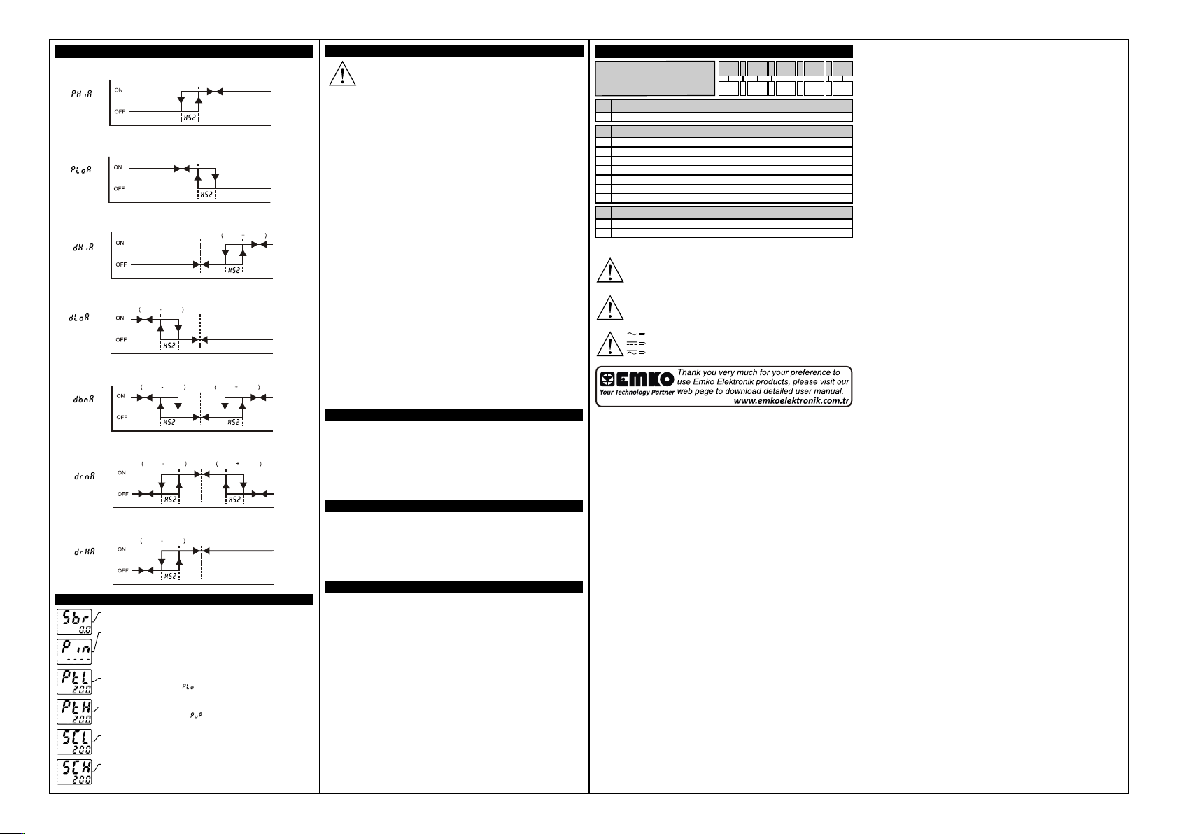
Alarm Types
Process H�gh
Alarm
Process Low
Alarm
Dev�at�on H�gh
Alarm
Dev�at�on Low
Alarm
Dev�at�on Band
Alarm
Dev�at�on Range
Alarm
Dev�at�on Range
H�gh Alarm
Error Messages
°C
°F
PO1
AL1
PO2
/
AL2
°C
°F
PO1
AL1
PO2
/
AL2
°C
°F
PO1
AL1
PO2
/
AL2
°C
°F
PO1
AL1
PO2
/
AL2
°C
°F
PO1
AL1
PO2
/
AL2
°C
°F
PO1
AL1
PO2
/
AL2
Alarm
Output
Alarm
Output
Alarm
Output
Alarm
Output
Alarm
Output
Output
Output
1-Sensor fa�lure �n analog �nputs. Sensor connect�on �s wrong or there
�s no sensor connect�on.
a
2-If programm�ng sect�on enter�ng password �s d�fferent from “0” and
user accesses to the parameter by enter button w�thout enter�ng the
password and wants to change a parameter, the warn�ng message �s
shown on the bottom d�splay as shown on the left. Dev�ce does not
allow to do any changes w�thout enter�ng the password correctly.
a
3-If value that �s read from the analog �nput �s lower than process set
low l�m�t parameter value ( ), value on the top d�splay starts to bl�nk
as shown on the p�cture.
a
4-If value that �s read from the analog �nput �s h�gher than process set
h�gh l�m �t parameter value ( ), value on the top d�splay starts to
bl�nk as shown on the p�cture.
a
5-If value that �s read from the analog �nput �s low er than sensor scale
low l�m�t, value on the top d�splay starts to bl�nk as shown on the
p�cture.
a
6-If value that �s read from the analog �nput �s h�gher than sensor scale
h�gh l�m�t, value on the top d�splay starts to bl�nk as shown on the
p�cture.
Set 1 Set 2 Set 1 Set 1 Set 2
Alarm
Set 1 Set 2 Set 1 Set 1 Set 2
Alarm
Set 1 Set 2 Set 1
Set 2
Process Value
Set 2
Process Value
Set 1 Set 1 Set 2
Process Value
Set 1Set 1 Set 2
Process Value
Process Value
Process Value
Process Value
Installat�on
Before beg�nn�ng �nstallat�on of th�s product, please
read the �nstruct�on manual and warn�ngs below
carefully.
In package,
-One p�ece un�t
-Two p�eces mount�ng clamp
-One p�ece �nstruct�on manual
A v�sual �nspect�on of th�s product for poss�ble damage occured
dur�ng sh�pment �s recommended before �nstallat�on. It �s your
respons�b�l�ty to ensure that qual�f�ed mechan�cal and electr�cal
techn�c�ans �nstall th�s product.
If there �s danger of ser�ous acc�dent result�ng from a fa�lure or defect
�n th�s un�t, power off the system and the electr�cal connect�on of the
dev�ce from the system.
The un�t �s normally suppl�ed w�thout a power sw�tch or a fuse. Use
power sw�tch and fuse as requ�red.
Be sure to use the rated power supply voltage to protect the un�t
aga�nst damage and to prevent fa�lure.
Keep the power off unt�l all of the w�r�ng �s completed so that electr�c
shock and trouble w�th the un�t can be prevented.
Never attempt to d�sassemble, mod�fy or repa�r th�s un�t. Tamper�ng
w�th the un�t may results �n malfunct�on, electr�c shock or f�re.
Do not use the un�t �n combust�ble or explos�ve gaseous
atmospheres. Dur�ng the equ�pment �s putted �n hole on the metal
panel wh�le mechan�cal �nstallat�on some metal burrs can cause
�njury on hands, you must be careful.
Montage of the product on a system must be done w�th �t’s mount�ng
clamp. Do not do the montage of the dev�ce w�th �nappropr�ate
mount�ng clamp. Be sure that dev�ce w�ll not fall wh�le do�ng the
montage.
It �s your respons�b�l�ty �f th�s equ�pment �s used �n a manner not
spec�f�ed �n th�s �nstruct�on manual.
Warranty
EMKO Elektron�k warrants that the equ�pment del�vered �s free from
defects �n mater�al and workmansh�p. Th�s warranty �s prov�ded for a
per�od of two years. The warranty per�od starts from the del�very
date.
Th�s warranty �s �n force �f duty and respons�b�l�t�es wh�ch are
determ�ned �n warranty document and �nstruct�on manual performs
by the customer completely.
Ma�ntenance
Repa�rs should only be performed by tra�ned and spec�al�zed
personnel. Cut power to the dev�ce before access�ng �nternal parts.
Do not clean the case w�th hydrocarbon-based solvents (Petrol,
Tr�chlorethylene etc.). Use of these solvents can reduce the
mechan�cal rel�ab�l�ty of the dev�ce. Use a cloth dampened �n ethyl
alcohol or water to clean the external plast�c case.
Other Informat�ons
Manufacturer Informat�on:
Emko Elektron�k Sanay� ve T�caret A.Ş.
Dem�rtaş Organ�ze Sanay� Bölges� Karanf�l Sk. No:6 16369
BURSA/TURKEY
Phone: +90 224 261 1900
Fax: +90 224 261 1912
a
Repa�r and Ma�ntenance Serv�ce Informat�on:
Emko Elektron�k Sanay� ve T�caret A.Ş.
Dem�rtaş Organ�ze Sanay� Bölges� Karanf�l Sk. No:6 16369
BURSA/TURKEY
Phone: +90 224 261 1900
Fax : +90 224 261 1912
Order�ng Informat�on
A
Eco LITE ( 48x48 DIN 1/16 )
D�mens�on
A
48x48 DIN 1/16
4
Supply VoltageB
100-240VV 50/60Hz1
24VW (±%15) 50/60Hz2
115VV (±%15) 50/60Hz
3
230VV (±%15) 50/60Hz
5
10...30VZ
6
24VV (±%15) 50/60Hz
7
9
Customer
Outputs-1
C
1 x Relay Output (5A@250VV at Res�st�ve Load) (NO,C)
1R
2 x Relay Output (5A@250VV at Res�st�ve Load) (NO,NO,C)
2R
Before comm�ss�on�ng the dev�ce, parameters must be set �n
accordance w�th des�red use. Incomplete or �ncorrect conf�gurat�on
can cause dangerous st�uat�ons.
Because of l�m�ted mechan�cal l�fe of relay output contact, SSR
output �s recommended wh�ch the dev�ce use PID control algor�tm.
The dev�ce w�th ON/OFF control algor�tm, hysteres�s parameter must
be set a su�table value for your system, to avo�d too much relay
sw�tch�ng.
Vac,
Vdc,
Vdc or Vac can be appl�ed
B.C.D
4 .
0 .E0
 Loading...