


| <![if ! IE]> <![endif]>Cooling Controller |
<![if ! IE]> <![endif]>ENGLISH |
<![endif]>ESM-3712-CN 77x35 DIN Size
ESM-3712-CN 77 x 35 DIN Size Digital , ON / OFF Cooling Controller
-4 Digits Display
-NTC Input or PTC Input (Must be determined in order.)
-Adjustable temperature offset
-Set value boundaries
-Operation selection of compressor operates continuously, stops or operates periodically in case of sensor defect
-Compressor protection delays
-Defrost time easily changeable from front panel
-Manual defrost capability from front panel
-Defrost parameters
-Alarm parameters
-Adjustable internal buzzer according to the defrost, sensor defect and alarm status
-Defrost time and/or manual defrost and/or temperature set value protection
-Password protection for programming section
-Installing parameters using Prokey
-Remote access, data collecting and controlling with Modbus RTU
-Having CE mark according to European Norms
Instruction Manual. ENG ESM-3712-CN 01 V06 11/15

1.Preface
ESM-3712-CN series cooling controllers are designed for controlling cooling process. They can be used in many applications with their easy-use, On / Off control form and defrost
properties. Some application and application fields which they are used are below:
Applications
Refrigerators Air Conditioning Storages Freezers
etc...
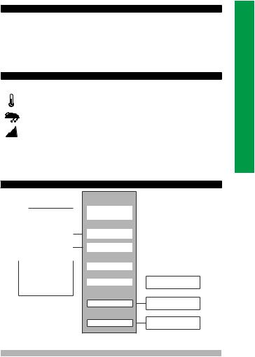
Operating Temperature : 0 to 50 °C
Max. Operating Humidity : 90% Rh (non-condensing)
Altitude |
: Up to 2000 m. |
cForbidden Conditions Corrosive atmosphere
Explosive atmosphere
Home applications (The unit is only for industrial applications)
1.2 General Specifications
|
Standard |
|
|
|
ESM-3712-C |
|
|
|
230VV ( ±%15) 50/60Hz |
|
|
|
|
|
|
|
Optional Supply Voltage |
|
|
|
|
|
|
|
|
|
|
Power Supply |
|
|
|
|
115 VV(±%15) 50/60Hz, |
|
|
|
|
|
|
|
|
|
|
Input |
|
|
|
|
24 VV(±%15) 50/60Hz, |
|
|
|
|
|
|
|
|
|
|
|
|
|
|
|
10 - 30 V Z |
|
|
|
|
|
|
|
|
|
|
|
|
|
|
|
NTC, PTC |
|
|
|
Evaporator |
|
|
|
|
|
|
Sensor Input |
|
|
|
|
|
|
|
|
|
|
|
|
|
|
|
|
|
|
|
|
NTC,PTC |
|
|
|
Cabinet |
|
|
|
|
|
|
Sensor Input |
|
|
|
|
|
|
|
|
|
|
|
Configurable Digital |
|
|
|
Digital Input |
|
|
|
Input |
|
|
|
|
|
|
|
|
|
|
|
|
|
||
- Stopping fan |
|
|
|
|
|
|
|
- Stopping compressor |
|
|
|
|
|
|
|
- Stopping fan and |
|
|
|
Compressor Input |
|
Cooling Function |
|
|
|||||||
|
compressor |
|
|
|
|
|
ON/OFF Operation |
- Manual defrost |
|
|
|
|
|
|
|
|
|
|
|
|
|
||
- Alarm |
|
|
|
|
|
|
|
|
|
|
|
|
Defrost Output |
|
Defrost Function |
|
|
|
|
|
|
|
ON/OFF Operation |
|
|
|
|
|
|
|
|
|
|
|
|
|
Fan Output |
|
Fan Control Output |
|
|
|
|
|
|
|
|
|
|
|
|
|
|
|
ON/OFF Operation |
2
<![endif]>ENGLISH

1.3 Installation
A visual inspection of this product for possible damage occurred during shipment is recommended before installation. It is your responsibility to ensure that qualified mechanical and electrical technicians install this product.
If there is danger of serious accident resulting from a failure or defect in this unit, power off the system and separate the electrical connection of the device from the system.
The unit is normally supplied without a power supply switch or a fuse. Use power switch and fuse as required.
Be sure to use the rated power supply voltage to protect the unit against damage and to prevent failure.
Keep the power off until all of the wiring is completed so that electric shock and trouble with the unit can be prevented.
Never attempt to disassemble, modify or repair this unit. Tampering with the unit may results in malfunction, electric shock or fire.
Do not use the unit in combustible or explosive gaseous atmospheres.
During putting equipment in hole on the metal panel while mechanical installation some metal burrs can cause injury on hands, you must be careful.
Montage of the product on a system must be done with it’s fixing clamps. Do not do the montage of the device with inappropriate fixing clamp. Be sure that device will not fall while doing the montage.
It is your responsibility if this equipment is used in a manner not specified in this instruction manual.
1.4 Warranty
EMKO Elektronik warrants that the equipment delivered is free from defects in material and workmanship. This warranty is provided for a period of two years. The warranty period starts from the delivery date. This warranty is in force if duty and responsibilities which are determined in warranty document and instruction manual performs by the customer completely.
<![endif]>ENGLISH
1.5 Maintenance
Repairs should only be performed by trained and specialized personnel. Cut power to the device before accessing internal parts.
Do not clean the case with hydrocarbon-based solvents (Petrol, Trichlorethylene etc.). Use of these solvents can reduce the mechanical reliability of the device. Use a cloth dampened in ethyl alcohol or water to clean the external plastic case.
1.6 Manufacturer Company
Manufacturer Company Name :
Emko Elektronik A.S .DOSAB Karanfil Sk.No:6 16369 BURSA/TURKEY Phone: +90 224 261 19 00
Fax: +90 224 261 19 12
Repair and maintenance service information:
Emko Elektronik Sanayi ve Ticaret A.Ş.
Demirtaş Organize Sanayi Bölgesi Karanfil Sk. No:6 16369 BURSA/TURKEY
Phone |
: +90 224 261 1900 |
Fax |
: +90 224 261 1912 |
3

2. General Description
Front Panel |
Mounting Clamp |
IP65 protection |
Panel Surface |
NEMA 4X |
|
|
(maximum thickness 15 mm / 0.59 inch) |
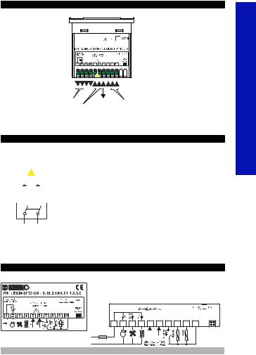
2.1 Front View and Dimensions of ESM-3712-CN Cooling Controller
Maximum 15 mm / 0.59 inch
OC OF |
S P |
|
<![if ! IE]> <![endif]>inch |
|
|
ESM-3712CN |
|
|
|
|
ü |
|
<![if ! IE]> <![endif]>mm / 1.36 |
|
|
|
|
<![if ! IE]> <![endif]>34,5 |
|
|
|
|
|
|
65 mm / 2.56 inch
76 mm / 3 inch
6 mm / 0.24 inch
2.2 Panel Cut-Out
110 mm / 4.33 inch (min)
| <![if ! IE]> <![endif]>/ 1.14 inch |
<![if ! IE]> <![endif]>50 mm / 1.97 inch (min) |
| <![if ! IE]> <![endif]>29 mm |
|
|
71 mm / 2.79 inch |
4
<![endif]>ENGLISH

2.3 Panel Mounting and Removing
1
ESM-3712CN |
ESM-3712CN |
1 |
3 |
|
2 |
|
|
|
2 |
|
|
1-Before mounting the device in your panel, make |
1-Pull mounting clamps from left and |
|
sure that the cut-out is of the right size. |
right fixing sockets. |
|
2-Insert the device through the cut-out. If the |
2-Pull the unit through the front side of |
|
mounting clamps are on the unit, put out them before |
the panel |
|
inserting the unit to the panel. |
Before starting to remove the unit |
|
3- Insert the mounting clamps to the fixing sockets |
from panel, power off the unit and |
|
that located left and right sides of device and make |
c the related system. |
|
the unit completely immobile within the panel |
|
|
3.Optinal Accessories |
|
|
1.RS-485 Module |
2.PROKEY Programming Module |
|
RS-485 Communication |
The device is programmed (Upload or |
Interface |
Download) by using the parameters. |
3. Using Prokey
TO USE PROKEY, VALUE OF THE PrC PARAMETER MUST BE ‘0’.
IF PrC=1 AND  BUTTON IS PRESSED


 MESSAGE WILL BE SHOWN. 10s. LATER DEVICE TURNS BACK TO THE MAIN OPERATION SCREEN OR YOU CAN PRESS SET BUTTON TO TURN BACK TO MAIN OPERATION SCREEN.
DOWNLOADING FROM DEVICE TO PROKEY
1.The device is programmed by using the parameters.
2.Energize the device then put in PROKEY and press  button.


 Message is shown on the display. When the loading has finished,


 message is shown.
3.Press any button to turn back to main operation screen. 4.Remove the PROKEY.
NOTE: 


 message is shown when an error occurs while programming. If you want to reload, put in PROKEY and press
  button. If you want to quit, remove PROKEY and press
  button. The device will turn back to main operation screen.
DOWNLOADING FROM PROKEY TO DEVICE
1.Switch off the device.
2.Put in PROKEY then energize the device.
3.When the device is energized, the parameter values in PROKEY, start downloading to the device automatically. At first, 


 message is shown on the display, when loading has finished,


 message is shown.
4.After 10 seconds device starts to operate with new parameter values. 5.Remove the PROKEY.
NOTE: 


 message is shown when an error occurs while programming. If you want to reload, switch off the device and put in PROKEY then energize the device. If you want to quit remove PROKEY and press
  button. The device will turn back to main operation screen.
<![endif]>ENGLISH
5
4. Electrical Wiring Diagram
1 |
2 |
3 |
4 |
5 |
6 |
7 |
8 |
9 |
10 |
|
|
|
|
a |
|
|
|
|
|
|
|
|
|
L |
N |
|
|
|
|
24VV ( ±%15) 50/60Hz ,
Relay Output |
Digital Input |
Cabinet and Evaporator Temperature |
Power Supply Input |
Sensor Input (NTC or PTC) |
|
230VV ( ±%15) 50/60Hz , |
|
|
115VV ( ±%15) 50/60Hz ,
24VV ( ±%15) 50/60Hz ,
10...30 VZ - 1.5 W Must be determined in order.
4.1 Supply Voltage Input Connection of the Device
Power Supply Connection |
Make sure that the power supply voltage is the same |
||||||||||
indicated on the instrument. |
|||||||||||
|
|
|
|
|
|
|
|
|
|
|
cSwitch on the power supply only after that all the electrical |
|
|
|
|
|
|
|
|
|
|
|
|
|
|
|
|
|
|
a |
|
|
|
connections have been completed. |
|
|
|
L |
|
N |
|
Supply voltage range must be determined in order. While |
|||||
|
|
|
5 |
|
6 |
|
|
installing the unit, supply voltage range must be controlled |
|||
|
|
|
|
|
|
and appropriate supply voltage must be applied to the unit. |
|||||
|
|
|
|
|
|
|
|
|
|
|
|
EXTERNAL |
|
|
<![if ! IE]> <![endif]>-1 |
|
|
|
|
|
|||
FUSE |
|
|
<![if ! IE]> <![endif]>Note |
|
|
There is no power supply switch on the device. So a power |
|||||
(1A T) |
|
|
|
|
|
|
Supply |
csupply switch must be added to the supply voltage input. |
|||
|
|
|
|
|
|
||||||
|
|
|
|
|
|
|
|
|
|
||
|
|
|
|
|
|
|
|
|
|
Switch |
Power switch must be two poled for seperating phase and |
cneutral, On/Off condition of power supply switch is very important in electrical connection.
Supply Voltage |
External fuse that on Vpower supply inputs must be on |
230VV ( ±%15) 50/60Hz , |
phase connection. |
115VV ( ±%15) 50/60Hz , |
External fuse that on Zpower supply inputs must be on (+) |
10...30 VZ - 1.5 W |
connection. |
Must be determined in order. |
|
Note-1 : External fuse is recommended. |
|
4.2 Device Label and Connection Diagram
230VV CONNECTION DIAGRAM
2x5A@ 250VV |
L
N
|
16(8)A |
|
|
|
|
|
|
|
|
@250VV1HP |
|
|
a |
|
|
|
|
||
|
. |
|
|
|
|
|
|
||
1 |
COMP |
3 |
4 |
7 |
8 |
9 |
10 |
||
2 |
5 |
6 |
|||||||
16A T Sigorta |
NTC |
NTC |
L |
N |
|
230 VV ± 15% |
|
|
50/60Hz - 1.5VA |
|
|
RS-485 or
PROKEY
6
<![endif]>ENGLISH
5.Front Panel Definition and Accessing to the Menus
BUTTON DEFINITIONS
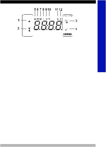
1. Increment Button :
**It is used to increase the value in the Set screen, Defrost screen and Programming mode.
2. Decrement, Silencing Buzzer and Downloading to Prokey Button :
**It is used to decrease the value in the Set screen, Defrost screen and Programming mode.
**It is used to silence the buzzer.
**If Prc =0, it is used to download from device to prokey.
3. Defrost Button :
**In the main operation screen; if this button pressed, defrost time value will be displayed. **In the main operation screen; if this button pressed for 3 seconds, manual defrost starts.
4. Set Button :
**In the main operation screen; if this button pressed, set value will be displayed. Value can be changed using increment and decrement buttons. When Set button pressed again, value is saved and returns back to main operating screen.
**To access the programming screen; in the main operation screen, press this button for 5 seconds.
**It is used to saving value in the Set screen, Defrost screen and programming screen.
LED DEFINITIONS
5. Compressor output led :
**This led indicates that compressor output is active. If any of compressor protection time active, this led blinks.
6.Defrost led :
**This led indicates that defrost output is active.
**Blinks once in a second while Defrost delay time.
**Blinks (5 Hz) while entering Defrost time value.
7.Alarm led :
**It is active when low alarm and high alarm statuses.
8.Celcius led :
**Indicates that device is in oC mode.
9.Fahrenheit led :
**Indicates that device is in oF mode.
10.Set led :
**Indicates that device is in Set value changing mode.
11.Program led :
**Blinks in programming mode .
<![endif]>ENGLISH
7
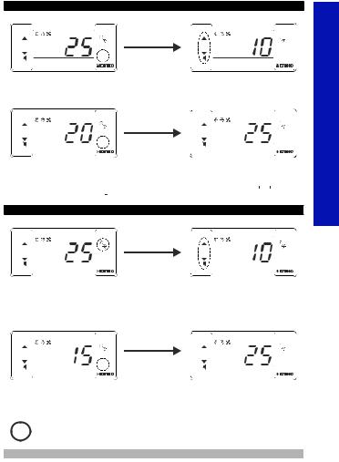
6. Changing and Saving Temperature Set Value
Main Operation Screen |
SET Value Screen |
||
|
ESM-3712CN |
|
ESM-3712CN |
OC OF |
S P |
OC OF |
S P |
ü |
ü |
When SET button pressed ‘’S’’ led will |
Temperature set value can |
||
be active and temperature set value will |
be changed with increment |
||
be displayed. |
|
and decrement buttons. |
|
|
|
Main Operation Screen |
|
|
ESM-3712CN |
|
ESM-3712CN |
OC OF |
S P |
OC OF |
S P |
ü |
ü |
When SET button pressed |
‘’S’’ will be inactive and goes back to |
temperature set value can be saved. |
main operation screen. |
Temperature set value parameter (Default=10) MODBUS ADDRESS:40001
Temperature set value, can be programmed between minimum temperature set value  and maximum temperature set value
  .
.
6.1 Changing and Saving Defrost Time Set Value
Main Operating Screen |
Defrost Time Value Screen |
||
|
ESM-3712CN |
|
ESM-3712CN |
OC OF |
S P |
OC OF |
S P |
|
ü |
|
ü |
When defrost button is pressed, defrost |
Change the defrost time set |
||
time set value is shown and defrost |
value with increment and |
||
output led starts to fast blink (5 Hz). |
decrement buttons. |
|
|
Defrost Time Value Screen |
Main Operating Screen |
||
|
ESM-3712CN |
|
ESM-3712CN |
OC OF |
S P |
OC OF |
S P |
ü |
ü |
Press set button for saving the defrost |
Defrost time set value is saved, defrost |
||
output led stop the fast blink (5 Hz), main |
|||
time set value |
|||
operation screen is shown. |
|||
|
|
||
i |
If no operation is performed in defrost time set value changing mode and temperature set |
||
value changing mode for 20 seconds, device turns to main operation screen automatically. |
|||
<![endif]>ENGLISH
8

6.2 Programming Mode Parameter List
Temperature Unit Selection Parameter ( Default = 0 ) MODBUS ADDRESS:40002
°C selected.
°F selected.
Decimal Seperator Enabling Parameter ( Default = 0 ) MODBUS ADDRESS:40003
Disable.
Enable.
Hysteresis Parameter for Compressor Output ( Default = 1 ) |
|
||
MODBUS ADDRESS:40004 |
|
|
|
from 1 to 20°C for NTC (-50°C, 100°C) or PTC (-50°C, 150°C) |
|
||
from 1 to 36°F for NTC (-58°F, 212°F) or PTC (-58°F, 302°F) |
|
||
from 0.1to 10.0°C for NTC (-50.0°C,100.0°C) or PTC (-50.0°C,150.0°C) |
|
||
from 0.1 to 18.0°F for NTC (-58.0°F,212.0°F) or PTC(-58.0°F,302.0°F) |
|
||
In ON/OFF control algorithm, |
Temperature |
|
|
temperature value is tried to keep equal |
|
|
|
to set value by opening or closing the last |
HSt |
HSt |
|
control element. ON/OFF controlled |
|
||
|
Set |
|
|
system, temperature value oscillates |
|
|
|
|
|
Time |
|
continuously. Temperature value’s |
|
|
|
oscillation period or amplitude around set |
Control |
|
|
value changes according to controlled |
|
Output |
|
system. For reducing oscillation period of |
ON |
Time |
|
temperature value, a threshold zone is |
|
OFF |
|
formed below or around set value and |
|
|
|
this zone is named hysteresis. |
|
|
|
Minimum Temperature Set Value Parameter(Default =Minimum Value of Device Scale) MODBUS ADDRESS:40005
Temperature set value can not be lower than this value. This parameter value can be adjusted from minimum value of device scale to maximum temperature set value parameter 
Maximum Temperature Set Value Parameter
(Default = Maximum Value of Device Scale) MODBUS ADDRESS:40006
Temperature set value can not be greater than this value.
This parameter value can be adjusted from minimum temperature set value parameter  to maximum value of the device scale.
Cabinet Sensor Offset Parameter ( Default = 0 ) MODBUS ADDRESS:40007
From -20 to 20 °C for NTC(-50°C, 100°C) or PTC(-50°C, 150°C), From -36 to 36 °F for NTC(-58°F, 212°F) or PTC(-58°F, 302°F),
From -10.0 to 10.0°C for NTC(-50.0°C,100.0°C) or PTC(-50.0°C,150.0°C), From -18.0 to 18.0°F for NTC(-58.0°F,212.0°F) or PTC(-58.0°F,302.0°F).
Evaporator Sensor Selection Parameter ( Default =1 ) MODBUS ADDRESS:40008
Evaporator sensor is inactive.
Evaporator sensor is active.
Evaporator Sensor Offset Parameter ( Default = 0 ) MODBUS ADDRESS:40009
If evaporator sensor selection parameter  is 1, then this parameter is observed. From -20 to 20°C for NTC(-50°C, 100°C) or PTC(-50°C, 150°C) ,
From -36 to 36°F for NTC(-58°F, 212°F) or PTC(-58°F, 302°F),
From -10.0 to 10.0°C for NTC(-50.0°C,100.0°C) or PTC(-50.0°C,150.0°C), From -18.0 to 18.0 °F for NTC(-58.0°F,212.0°F) or PTC(-58.0°F,302.0°F).
Defrost Type Selection Parameter ( Default =0 ) MODBUS ADDRESS:40010
Electric defrost.
Hot gas defrost.
Defrost Time Parameter ( Default =10 ) MODBUS ADDRESS:40011
It can be adjusted from 0 to 999 minutes.
If it is selected 0 automatic or manual defrost is not performed.
Defrost Repeat Cycle Parameter ( Default = 1 ) MODBUS ADDRESS:40012
It can be adjusted from 1 to 99 hours.
<![endif]>ENGLISH
9

Defrost Stopping Temperature Parameter (Default = 2°C) MODBUS ADDRESS:40013
For evaporator sensor selection parameter  is 1 (evaporator sensor is active), while defrost operation, if evaporator temperature reaches to temperature that defined at this parameter in a shorter time than
  parameter, then defrost operation stops.
Defrost at Power On Selection and Defrost Delay Parameter ( Default =  ) MODBUS ADDRESS:40014
It can be adjust from 0 to 99 minutes. When tihs parameter is 0, if decrement button is pressed, is observed. In this condition system goes through a defrost cycle at the end of the defrost repeat cycle time
  after power on.If this parameter value is between 0 and 99, then system goes through a defrost cycle at the end of the this parameter time after power on.
Display Status During Defrost Parameter ( Default = 3 )
MODDBUS ADRESS:40015
The cabinet temperature value is displayed during defrost.
Cabinet temperature value at the start of the defrost is displayed during defrost.
Temperature set value is displayed during defrost.
 is displayed to indicate the defrost is in progress.
Displaying Current Temperature Delay After Defrost Parameter ( Default = 0 ) MODDBUS ADRESS:40016
This parameter defines the delay for displaying current temperature being active after defrost. It can be adjusted from 0 to 255 minutes.
Dripping Time Parameter (Default = 2) MODBUS ADDRESS:40017
This parameter defines for dripping time after defrost. It can be adjusted from 0 to 15 minutes.
Temperature Alarm Delay After Dripping Parameter (Default = 0) MODBUS ADDRESS:40018
This parameter defines the delay for temperature alarm being active after dripping time completion. It can be adjusted from 0 to 15 minutes.
Compressor Start Delay at Power On Parameter ( Default = 0 ) MODBUS ADDRESS:40019
When power is first applied to the device,This time delay must be expired for activation of compressor. It can be adjusted from 0 to 20 minutes.
Compressor Start-Start Delay Parameter ( Default = 0 ) MODBUS ADDRESS:40020
This time delay must be expired between two activation of the compressor. It can be adjusted from 0 to 20 minutes.
Minimum Compressor OFF Time Parameter ( Default = 0 )MODBUS ADDREDS:40021
When compressor is inactive, this time delay must be expired for activation of the compressor. It can be adjusted from 0 to 20 minutes.
Minimum Compressor ON Time Parameter ( Default = 0 )MODBUS ADRES:40022
When compressor is active, this time delay must be expired for deactivation of the compressor. It can be adjusted from 0 to 20 minutes.
Cabinet Probe Defect Parameter ( Default = 0 ) MODBUS ADDRESS:40023
Compressor is OFF in case of cabinet probe defect.
Compressor is ON in case of cabinet probe defect.
Compressor operates periodically according to  and
and  time periods in case of cabinet probe defect.
Compressor Active Time in Case of Cabinet Probe Defect Parameter (Default = 0) MODBUS ADDRESS:40024
If cabinet probe defect parameter  is 2, then this parameter is observed. It canbe adjusted from
  to 99 minutes.
Compressor İnactive Time in Case of Cabinet Probe Defect Parameter ( Default = 0 ) MODBUS ADDRESS:40025
If cabinet probe defect parameter  is 2, then this parameter is observed. It canbe adjusted from
  to 99 minutes.
<![endif]>ENGLISH
10
Temperature Alarm Function Selection Parameter ( Default = 0 )
MODBUS ADRES:40026
Temperature alarm function is inactive.
Absolute alarm is selected. If temperature lower than |
and higher than |
, then alarm is on. |
|
Relative alarm is selected. Alarm operates according to the set value. If cabinet temperature value is below ( Set -  ) or above ( Set +
  ), alarm ocurs.
Temperature Alarm Minimum Parameter
(Default = Minimum Value of Device Scale) MODBUS ADRES:40027
For 


 = 1, this parameter value can be adjusted from minimum value of device scale to temperature alarm maximum parameter
  value. For


 = 2, this parameter value can be adjusted 0 to %50 of the device scale.
Temperature Alarm Maximum Parameter
(Default =Maximum Value of Device Scale ) MODBUS ADRES:40028
For 


 = 1, this parameter value can be adjusted from temperature alarm minimum parameter
  value to maximum value of device scale.For


 = 2, this parameter value is can be adjusted 0 to %50 of the device scale.
Temperature Alarm On Delay Time Parameter(Default = 0) MODBUS ADDRESS:40029
Temperature Alarm On Delay Time can be defined with this parameter. It can be adjusted from 0 to 99 minutes.
Temperature Alarm Delay After Power On Parameter(Default = 0) MODBUS ADDRESS:40030
When power is first applied to the device, this time delay must be expired for activation of temperature alarm. It can be adjusted from 0 to 99 minutes.
Fan Operation Selection Parameter (Default = 1) MODBUS ADDRESS:40031
Fan is OFF.
Fan is ON.
Fan operates according to the evaporator sensor temperature value. Fan operates according to the ( cabinet - evaporator ) temperature value.
Fan Stopping Temperature Parameter (Default = 2°C) MODBUS ADDRESS:40032
Fan stopping temperature can be defined with this parameter. It can be adjusted from minimum value to maximum value of device scale.
Hsyteresis Parameter for Fan Output (Default = 1 ) MODBUS ADDRESS:40033
From 1 to 20°C for NTC (-50°C, 100°C) , from 1 to 36°F for NTC (-58°F, 212°F), from 0.1 to 10.0°C for NTC (-50.0°C,100.0°C), from 0.1 to 18.0°F for NTC (-58.0°F,212.0°F)
Fan Activity Selection According to the Compressor and Defrost (Default = 0) MODBUS ADDRESS:40034
Fan operates according to the 


 parameter.
Fan operates according to the 


 parameter, but fan is stopped if commpressor is stops.
Fan operates according to the 


 parameter, but fan is stopped during defrost and dripping time.
Fan operates according to the 


 parameter.If compressor stops, during defrost and dripping operations fan stops.
Fan Delay Time After Completion of Dripping Time Parameter (Default = 2) MODBUS ADDRESS:40035
Fan Delay Time After Completion of Dripping Time is defined with this parameter. It can be adjusted from 0 to 15 minutes.
<![endif]>ENGLISH
11

Digital Input Contact Selection Parameter ( Default = 1 ) MODBUS ADDRESS:40036
Digital input is inactive.
NO “normally open” digital input is active when the contact is closed. NC “normally close” digital input is active when the contact is opened.
Digital Input Function Selection Parameter ( Default = 0 ) MODBUS ADDRESS:40037
If digital input contact selection parameter value 


 = 0, this parameter is not observed.


 When the digital input is active, fan is stopped.


 screen will be displayed.
When the digital input is active, compressor is stopped.


 screen will be displayed and defrost operation will be disabled. If Buzzer function selection parameter


 = 2 or 4 buzzer is active.
When the digital input is active, first fan stops, 10 seconds later compressor stops. 


 will be displayed at main operation screen.
When the digital input is active, defrost starts.
When the digital input is active, alarm will be active. 


 will be displayed at main operation screen. If Buzzer function selection parameter


 = 2 or 4 buzzer is active.
Digital Input Effect Time Parameter ( Default =  ) MODBUS ADDRESS:40038
If digital input contact selection parameter value 


 = 0, this parameter is not observed. For digital input function selection parameter


 = 0 or 2, maximum effect time of digital input is determined with this parameter. It can be adjust from 0 to 120 minutes. When this parameter is 0, if decrement button is pressed,
  is observed. In this condition the effect will be ended when digital input is deactive.
Buzzer Function Selection Parameter ( Default = 0 ) MODBUS ADDRESS:40039
Buzzer is inactive.
Buzzer is active during defrost operation.
Buzzer is active if an alarm occurs.
Buzzer is active during cabinet sensor failures.
Buzzer is active during defrost, alarm or cabinet sensor failures.
Buzzer Active Time ( Default =  ) MODBUS ADDRESS:40040
If buzzer function selection parameter value 


 = 0, this parameter is not observed. Buzzer active time can be define with this parameter. It can be adjusted from 1 to 99 minutes. When this parameter is 1, if decrement button is pressed,
 is observed. In this condition buzzer is active till buzzer silence button is pressed.
Button Protection Parameter ( Default = 0 ) MODBUS ADDRESS:40041
There is no protection.
Defrost time set value can not be changed and manual defrost is not available.
Temperature set value can not be changed.
Defrost time set value and temperature set value can not be changed and manual defrost is not available.
Defrost time can not be changed,Defrost ON/OFF operation is available.
Communication Mode Selection Parameter( Default = 0 ) MODBUS ADRESS:40042
PROKEY communication selected.
RS485 communication selected.
Slave ID Parameter ( Default = 1 ) MODBUS ADDRESS=40043
Device communication address parameter (1 to 247)
Programming Mode Accessing Password ( Default = 0 ) MODBUS ADDRESS:40044
It is used for accessing to programming mode. It can be adjusted from 0 to 999. If it is 0, password is not entered for accessing to the parameters. If password is ‘12’ only 


 ,
,


 ,
,


 can be accesible.
<![endif]>ENGLISH
12

6.3 Operation Graphics of ESM-3712-CN Cooling Controller
1- Defrost time parameter value 
 1,
1,
Defrost repeat cycle parameter value 
 1,
1,
Defrost at power on selection and defrost delay parameter value 


 1, Dripping time parameter value
 1 ise;
Power
ON |
|
|
OFF |
|
Time |
|
|
|
ON |
|
|
OFF |
|
Time |
Evap.°C |
|
|
Sensor |
|
|
Temp. |
|
|
Defrost |
|
Time |
Manual defrost button |
||
Output |
starts |
time |
Led |
|
|
ON |
|
|
OFF |
|
Time |
Defrost |
|
|
|
|
|
Output |
|
|
ON |
|
Time |
OFF |
|
|
|
|
|
2- Compressor start delay at power on parameter value |
1, |
|
Compressor start - start delay parameter value |
1, |
|
Minimum compressor OFF time parameter value |
1, |
|
Minimum compressor ON time parameter value |
1 ise; |
|
Power |
|
|
ON |
|
|
OFF |
|
Time |
Cab. °C |
|
|
|
|
|
Sensor |
|
|
Temp. |
Hst |
|
SET |
|
|
|
|
|
|
|
Time |
Comp.
Output
Led
ON |
|
|
OFF |
Time |
|
Comp. |
||
Output |
|
|
ON |
Time |
|
OFF |
||
|
<![endif]>ENGLISH
13

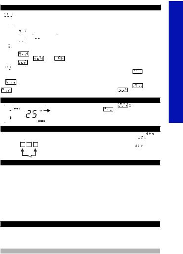
6.4 Entering To The Programming Mode, Changing and Saving Parameter
Main Operating Screen
|
ESM-3712CN |
|
ESM-3712CN |
OC OF |
S P |
OC OF |
S P |
ü |
ü |
When SET button is pressed for 5 |
Note1: If programming mode |
Programming Mode |
|
seconds, “P” led starts to blink. If |
accessing password is 0, |
Entering Screen |
|
programming mode entering |
Temperature Unit Selection |
Press SET button for |
|
password is different from 0, |
Screen |
is observed |
accessing to the |
programming mode entering screen |
instead of programming |
password entering screen. |
|
will be observed. |
screen accessing password |
|
|
ESM-3712CN |
|
|
ESM-3712CN |
OC OF |
S P |
OC OF |
S P |
ü |
ü |
Password Entering Screen |
Password Entering Screen |
Enter programming mode accessing |
Press SET/OK button for |
password with increment and decrement |
entering the password. |
Note-2: If programming mode accessing password is 0 parameter values can be seen.But parameter values can not be changed.
Programming Screen
ESM-3712CN |
ESM-3712CN |
OC OF |
S P |
OC OF |
S P |
ü |
ü |
Press SET button for accessing to the parameter value. Press increment button for accessing to the next parameter, press decrement button for accessing to the previous parameter
ESM-3712CN
OC OF S P
ü |
Compressor Output
Hysteresis Parameter Value
Compressor Output
Hysteresis Parameter Value
Change the value with increment and decrement buttons.
ESM-3712CN


 OC OF S P
ü |
Compressor Output
Hysteresis Parameter
|
Press set button for saving |
Press increment button for accessing to the |
|
the parameter. |
next parameter, press decrement button for |
i |
|
accessing to the previous parameter |
If no operation is performed in programming mode for 20 seconds, device turns to main |
||
operation screen automatically.. |
|
|
7. Failure Messages in ESM-3712-CN Cooling Controller
1-  message blinking.Cabinet temperature sensor failure. Sensor connection is wrong or there is no sensor connection. While this message shown on this display, if buzzer function selection parameter
  is 3 or 4, internal buzzer starts to operate.
14
<![endif]>ENGLISH
7. Failure Messages in ESM-3712-CN Cooling Controller
2- message blinking.
Evaporator temperature sensor failure. sensor connection is wrong or there is no sensor connection.
3- message blinking.
For absolute alarm, if cabinet temperature sensor value is lower than temperature alarm minimum parameter  value and for relative alarm, if cabinet temperature sensor value is lower than (Temperature Set -
  ), then
  message starts to blink.If buzzer function selection parameter
  is 2 or 4, internal buzzer starts to operate.
4- message blinking.
For absolute alarm, if cabinet temperature sensor value is higher than temperature alarm maximum
parameter |
value and for relative alarm, if cabinet temperature sensor value is higher than |
||
(Temperature Set + |
), then |
message starts to blink. If buzzer function selection |
|
parameter |
is 2 or 4, internal buzzer starts to operate. |
||
5-  message blinking.
When the digital input is active and digital input function selection parameter value 


 is 0 or 2
  message starts to blink.
6- |
message blinking. |
|
|
When the digital input is active and digital input function selection parameter value |
is 1 or 4 |
||
|
message starts to blink. If buzzer function selection parameter |
is 2 or 4, internal buzzer |
|
starts to operate. |
|
|
|
8. Manual Defrost Operation with Defrost Button
ESM-3712CN |
While defrost time parameter value |
1, button |
|
OC OF S P |
3 sn. protection parameter value |
= 0 or 2 and defrost output is |
|
|
|||
|
inactive, in main operation screen if defrost button is pressed |
||
ü |
for 3 seconds manual defrost will be active. |
|
|
8.1 Manual Defrost Operation with Digital Input
DIGITAL INPUT |
While digital input function selection parameter value |
|
|
=3 |
||||||
if digital input contact selection parameter value |
|
|
|
|
=1 |
|
||||
7 |
8 |
9 |
(normally open NO) and the K switch is getting closed, or if |
|||||||
digital input contact selection parameter value |
|
|
|
=2 |
|
|||||
(normally close NC) and the K switch is getting opened manual defrost will be active
K
9.Modbus Adresses of Device Status Parameters (Read Input Register)
MODBUS ADRES:30001 |
Cabinet Temperature Value |
||
MODBUS ADRES:30002 |
Evaporator Temperature Value |
||
MODBUS ADRES:30003 |
Led Status |
: |
0.bit oC Led, 4.bit Fan Led, 5.bit Defrost Led, |
|
|
|
6.bit Compressor Led, 7.bit Alarm Led |
MODBUS ADRES:30004 |
Device Status : |
13.bit Programming Led, 14.bit Set Led |
|
0.bit Alarm Status, 1.bit Buzer Status |
|||
|
|
|
2.bit Cabinet Sensor Lost Status, |
|
|
|
3.bit Evaporator Sensor Lost Status |
MODBUS ADRES:30005 |
|
|
7.bit Defrost Status |
Output Status : 0.bit Compressor Output |
|||
|
|
|
1.bit Defrost Output |
MODBUS ADRES:30006 |
|
|
2.bit Fan Output |
Device Type and Version |
|||
10. Specifications
Device Type : Cooling Controler
Housing&Mounting: 76 mm x 34.5 mm x71 mm plastic housing for panel
Panel cut-out is 71 x 29 mm
Protection Class : NEMA 4X (IP65 at front, IP20 at rear )
<![endif]>ENGLISH
15
10. Specifications
Weight |
: Approximately 0.2 Kg |
|
Environmental Ratings |
: Standard, indoor at an altitude of less than 2000 meters |
|
|
|
with none condensing humidity. |
Storage / Operating Temperature : -40 oC to +85 oC / 0 oC to +50 oC |
||
Storage / Operating Humidity |
: 90 % max. (None condensing) |
|
Installation |
: Fixed installation |
|
Overvoltage Category |
: |
II. |
Pollution Degree |
: II, office or workplace, none conductive pollution |
|
Operating Conditions |
: Continuous |
|
Supply Voltage and Power |
: 230VV ( ±%15) 50/60Hz - 1.5VA |
|
|
: 115VV ( ±%15) 50/60Hz - 1.5VA |
|
Temperature Sensor Inputs |
: 24VV ( ±%15) 50/60Hz - 1.5VA, 10-30VZ 1.5W |
|
: NTC or PTC |
||
NTC Input Type or PTC Input Type: NTC (10 kW @25 °C ) or PTC (1000 W @25 °C ) |
||
Accuracy |
: ±1 % of full scale for thermoresistance |
|
Sensor Break Protection |
: Upscale |
|
Sampling Cycle |
: 3 samples per second |
|
Control Form |
: ON / OFF |
|
Relay Outputs |
: 16(8) A@250 V V at resistive load(Compressor Output) |
|
Display |
|
5 A@250 V V at resistive load(Defrost and Fan Output) |
: 14 mm Red 4 digit LED Display |
||
LED |
: S (Green), P (Green), oC (Yellow), oF(Yellow), |
|
|
|
Alarm(Red), Defrost Output (Red), Fan Output (Red) |
Internal Buzzer |
|
Compressor Ouput (Red), |
: |
83dB |
|
Approvals |
: |
, |
<![endif]>ENGLISH
A BC D E / FG HI / U V W Z
(77x35 DIN Size)
0 |
/ |
/ 1 |
0 0 |
A Supply Voltage
324VV ( ±%15) 50/60Hz - 1.5VA
4115VV ( ±%15) 50/60Hz - 1.5VA
5230VV ( ±%15) 50/60Hz - 1.5VA
810 - 30 V Z
BC Input Type |
Scale(°C) |
||
12 |
PTC (Note-1) |
-50°C/-58°F ; 150°C/302°F |
|
18 |
NTC (Note-1) |
-50°C/-58°F ;100°C/212°F |
|
E |
Compressor Output |
|
|
1 Relay Output ( 16(8) A@250 V V at resistive load, 1 NO ) |
|||
FG Defrost Output |
|
|
|
01 Relay Output ( 5 A@250 V V at resistive load, 1 NO ) |
|||
HI Fan Output
01 Relay Output ( 5 A@250 V V at resistive load, 1 NO )
V Temp. Sensor which is given with ESM-3712-CN
0None
1PTC-M6L40.K1.5 (PTC Air Probe with 1.5 mt silicon cable)
2PTCS-M6L30.K1.5.1/8” (PTC Liquid Probe with1.5 mt silicon cable)
3NTC-M5L20.K1.5 (NTC Sensor, thermoplastic moulded with
1.5m cable for cooling application)
4NTC-M6L50.K1.5 (NTC Sensor, stainless steel housing with
1.5m cable for cooling application)
9 Customer
All order information of ESM-3712-CN Cooling Controller are given on the table at left. User may form appropriate device configuration from information and codes that at the table and convert it to the ordering codes.
Firstly, supply voltage then other specifications must be determined. Please fill the order code blanks according to your needs.
Please contact us, if your needs are out of the standards.
Note-1:If input type is selected PTC or NTC (BC= 12, 18), Temperature sensor is given with the device.For this reason, if input type is selected as PTC,sensor type (V = 0,1 or 2) or if input type is selected as NTC, sensor type (V =0,3 or 4) must be declared in ordering information.
V Ş Vac,
ZŞ Vdc
cW Ş Vdc or Vac can be applied
Thank you very much for your preference to use Emko Elektronik products, please visit our
Your Technology Partner web page to download detailed user manual. www.emkoelektronik.com.tr
16

<![endif]>Kühlregler
<![if ! IE]><![endif]>ESM-3712-CN 77x35 DIN Maß
<![endif]>DEUTSCH
ESM-3712-CN 77 x 35 DIN Maß
Digitaler EIN / AUS Kühlregler
-4-stellige Anzeige
-NTC Eingang oder PTC Eingang (Muss vorher festgelegt werden)
-3 Ausgänge für Kompressor, Abtauund Ventilatorregelung
-2 Sensoreingänge für Kühlfach und Verdampfer
-Konfigurierbarer Digitaleingang
-EIN / AUS Schalter
-2 getrennt einstellbare abweichende Werte für den Kühlfach-und den Verdampfersensor
-Begrenzung der einstellbaren Werte
-Beim Ausfall des Kühlfachsensors ist ein Dauerbetrieb des Kompressors, aber auch Kompressor-Stop oder ein periodischer Betrieb möglich.
-Kompressor-Schutzschalter mit Verzögerung
-Wahlweise 2 Abtaufunktionen (mit heißem Gas oder elektrisch )
-Auf der Frontplatte einstellbare Abtauzeit
-Manuelles Abtauen von der Frontplatte aus
-Abtauparameter
-Alarmparameter
-Ventilator läuft abhängig vom Kompressor und vom Abtauvorgang
-Ventilator läuft abhängig von der Verdampfertemperatur oder der Kühlfachtemperatur.
-Einstellbarer, eingebauter Summer signalisiert das Abtauen, einen Kühlfachsensorschaden und einen Alarmstatus.
-Automatisches oder manuelles Abtauen und/oder Schutz der eingestellten Temperaturwerte
-Programmiermodus mit Passwortschutz
-Installationsparameter von Prokey
-Fernregelung, Datenkontrolle und Regelung mit Modbus RTU
-EU-Kennzeichnung gebaut nach den europäischen Normen
Bedienungsanleitung: DE ESM-3712-CN 02 V02 09/12
1.Vorwort:
Kühlregler der Serie ESM-3712-CN sind dafür konstruiert, den Kühlprozess zu steuern. Sie sind sehr vielfältig einsetzbar, wegen ihres einfachen Gebrauchs, ihrer EIN-und AUS-Schaltfunktion und ihrer Abtaufunktion.Einige der Anwendungsbereiche und Anwendungen sind unten aufgelistet:
Anwendungsbereiche |
Anwendungen |
Lebensmittel |
Kühlschränke |
Maschinen Produktion Industrie |
Klimaanlagen |
u.s.w. |
Kühlhäuser |
|
Tiefkühltruhen |
|
u.s.w. |
1.1 Umweltfreundlichkeit:
Betriebstemperatur |
: 0 bis 50 °C |
Max. Luftfeuchtigkeit |
: 90% r.L. (kein Kondenswasser) |
Höhe ü.M. |
: Bis zu 2000 m. |
Unzulässig: Korrosive Umgebung Explosive Atmosphäre
Verwendung im Heimbereich (Gerät ist nur für industrielle Anwendung gedacht)
1.2 Technische Daten:
|
Standard |
|
|
|
ESM-3712-CN |
|
|
230V |
( ±%15) 50/60Hz |
|
|
|
|
|
Andere Spannungen: |
|
|
|
Anschlusswerte- |
|
|
115 V |
(±%15) 50/60Hz |
|
|
|
Stromversorgung |
|
10 - 30 V |
|
|
|
|
|
|
|
|
|
|||
|
|
|
|
|
|
|
|
NTC,PTC |
|
|
|
Sensoreingang |
|
|
|
|
|
Verdampfer |
||
|
|
|
|
|
|
|
|
|
|
|
|
|
|
|
|
|
|
|
|
|
|
NTC,PTC |
|
|
|
Sensoreingang |
|
|
|
|
|
Kühlfach |
||
|
|
|
|
|
|
|
|
|
|
|
|
|
|
|
|
|
|
|
|
|
Konfigurierbarer |
|
|
|
|
||
|
|
|
Digitaler Eingang |
|||
Digitaleingang |
|
|
|
|||
-Ventilator Stop
-Kompressor Stop
- Ventilator und |
Kompressoreingang |
|
Kühlfunktion |
Kompressor Stop |
|
EIN/Aus-Betrieb |
-Manuelles Abtauen
-Alarm
Abtaufunktion
Ausgang Abtauvorgang
EIN/Aus-Betrieb
Regelausgang-Ventilator
Ventilatorausgang
EIN/Aus-Betrieb
2
<![endif]>DEUTSCH

1.3 Installation
Vor Montage das Gerät visuell prüfen, ob das Gerät während der Beförderung beschädigt wurde.Die Montage und Inbetriebnahme muss durch geschultes Personal ausgeführt werden. Dies steht unter der Verantwortung des Käufers.
Falls aufgrund eines Fehlers oder einer Störung des Geräts eine Gefahr bestehen sollte, Spannungsversorgung abschalten und alle elektrischen Verbindungen zum Geräts entfernen.
Standardmäßig wird das Gerät ohne Netzschalter und ohne Sicherung ausgeliefert.
Bei Bedarf müssen diese vom Anwender selbst angebracht werden.
Es muss eine zum Gerät passende Versorgungsspannung verwendet werden, um Fehlfunktionen und Schäden zu vermeiden.
Um einen elektrischen Schock und ähnliche Unfälle zu vermeiden, darf das Gerät vor Abschluss der Verkabelung nicht mit Spannung versorgt werden.
An dem Gerät keine Veränderungen vornehmen, und das Gerät nicht reparieren.
Eingriffe am Gerät können fehlerhafte Funktion, Beschädigung des Geräts oder angeschlossener Geräte, elektrischen Schocks und Feuer auslösen.
Das Gerät darf unter keinen Umständen in der Nähe von brennbaren und explosiven Gasen verwendet werden.
Die Schalttafelausschnitte können scharfe Kanten aufweisen, welche bei der Montage des Geräts Schnittverletzungen verursachen können. Bitte treffen Sie die erforderlichen Vorsichtsmaßnahmen.
Es ist wichtig, dass das Gerät mit den mitgelieferten Befestigungsteilen montiertwird.
Das Gerät nicht mit ungeeigneten montieren. Achten Siedarauf, dass das Gerät während der Montage nicht herunterfällt.
Es unterliegt Ihrer Verantwortung, wenn das Gerät nicht wie in dieser Anleitung beschrieben, verwendet wird.
1.4 Garantie
2 Jahre Garantieschutz gegen Materialund Verarbeitungsfehler.
Diese Garantie wird mit dem Vorbehalt gewährleistet, dass der Kunde den in Garantieschein und Bedienungsanleitung erwähnten Pflichten nachkommt.
1.5 Instandhaltung
Das Gerät muss durch geschultes Personal gewartet werden. Vor dem Zugriff auf Innenteile, alle stromführenden Leitungen trennen. Gerät nicht mit auf Kohlenwasserstoff basierenden Lösungsmitteln (wie Benzin, Trichlorethylen etc.) reinigen. Das Reinigen mit diesen Lösungen kann die mechanische Sicherheit des Geräts vermindern. Verwenden Sie ein mit Ethylalkohol oder Wasser benetztes Tuch um das Plastikgehäuse außen zu reinigen.
1.6 Sonstige Angaben
Information des Herstellers:
Emko Elektronik Sanayi ve Ticaret A.Ş.
Demirtaş Organize Sanayi Bölgesi Karanfil Sk. No:6 16369 BURSA
Tel : +90 224 261 1900
Fax : +90 224 261 1912
Information über Reparatur und Wartungsdienst
Emko Elektronik Sanayi ve Ticaret A.Ş.
Demirtaş Organize Sanayi Bölgesi Karanfil Sk. No:6 16369 BURSA
Tel : +90 224 261 1900
Fax : +90 224 261 1912
<![endif]>DEUTSCH
3

2. Allgemeine Beschreibung:
Vorderseite: |
Halteklammern |
Schutzklasse IP-65 |
Frontplatte |
NEMA 4X |
|
|
(max. Dicke 15 mm / 0.59 Zoll) |
2.1 Vorderansicht und Abmessungen des ESM-3712-CN Kühlregelung
Maximal 15 mm / 0.59 Zoll
OC OF |
S P |
ESM-3712CN |
<![if ! IE]> <![endif]>Zoll |
|
|
|
|
|
|
|
<![if ! IE]> <![endif]>34,5 mm / 1.36 |
76 mm / 3 Zoll |
|
|
65 mm / 2.56 Zoll |
|
|
6 mm / 0.24 Zoll |
|
|
|
|
2.2 Schalttafelausschnitt
110 mm / 4.33 Zoll (min)
| <![if ! IE]> <![endif]>/ 1.14 Zoll |
<![if ! IE]> <![endif]>50 mm / 1.97 Zoll (min) |
| <![if ! IE]> <![endif]>29 mm |
|
|
71 mm / 2.79 Zoll |
<![endif]>DEUTSCH
4
 Loading...