

Page 1
Instruction Manual
D101728X012
3710 and 3720 Positioners
Fisherr 3710 and 3720 Valve Positioners and
3722 Electro-Pneumatic Converter
January 2015
Contents
Introduction 2.................................
Scope of Manual 2.............................
Description 2.................................
Positioner to Actuator Mountings List 5.......
Specifications 6...............................
Educational Services 6.........................
Installing the 3722 Converter 6...................
Hazardous Area Classifications and
Special Instructions for “Safe Use” and
Installation in Hazardous Areas
for 3722 Converter 7.......................
CSA 7....................................
FM 8.....................................
ATEX 8...................................
IECEx 10..................................
Installation 11................................
Mounting the Positioner 11......................
Installing the 3710 or 3720
Pneumatic Positioner on Size 25 or 50
585 and 585R Actuators 16..................
Connections 18................................
Supply Connection 19..........................
Output Connections 20........................
Instrument Connection 20......................
Vent Opening, Purge Option, and Actuator
Vent Connection 20.........................
Connecting the Purge Tube 22...............
Electrical Connection for the 3720
Positioner 22...............................
Diagnostic Connections 23.....................
Calibration 25..................................
Setting the Initial Cam Position 25...............
Zero and Span Adjustments 26..................
Standard or Beacon Indicator Alignment 27........
Changing Positioner Action 28....................
Single‐Action/Double‐Action 29.................
Direct‐Action/Reverse‐Action 29.................
Split‐Range Operation 30.......................
Changing the Spool Valve
(To Increase Positioner Output Capacity) 30.....
Changing the Span Adjuster Assembly
(To Change Positioner Input Range) 32.........
Principle of Operation 33........................
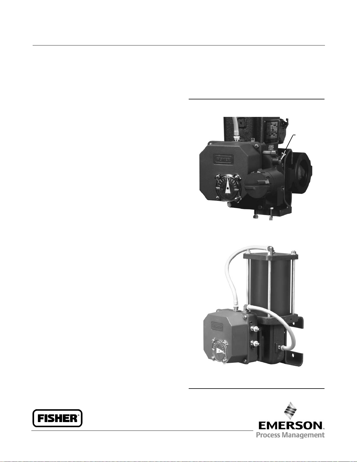
Figure 1. Positioners
SUPPLY
CONNECTION
W6144
3720 POSITIONER MOUNTED ON
A FISHER 1052 ACTUATOR
W6058‐1
3710 POSITIONER MOUNTED ON
A FISHER 1066 ACTUATOR
www.Fisher.com
Page 2

3710 and 3720 Positioners
January 2015
Instruction Manual
D101728X012
Contents (cont'd)
Maintenance 34................................
Positioner Maintenance 34......................
Replacing the Standard or Beacon Indicator 34.
Removing the 3722 Converter 35............
Removing the Positioner 35.................
Removing the Feedback Arm Assembly 36.....
Disassembling the Feedback Arm Assembly
and Span Adjuster Assembly 37............
Removing the Feedback Shaft (Cam Shaft) 37..
Disassembling the Spool Valve, Action Block,
and Gasket 37..........................
Disassembling the Input Module and
Summing Beam Assembly 38.............
Replacing the Input Module Diaphragm 39.....
Assembling the Input Module and Summing
Beam Assembly 40......................
Assembling the Spool Valve, Action Block,
and Gasket 41..........................
Assembling the Feedback Shaft
(Cam Shaft) 42..........................
Introduction
Replacing the Feedback Arm Assembly
and Span Adjuster Assembly 42............
3722 Converter Maintenance 42.................
Replacing the Converter Primary O‐Ring
and Filter 42............................
Disassembling the 3722 Converter 43.........
Assembling the 3722 Converter 43...........
Testing the 3722 Converter Module 44........
Parts Ordering 44...............................
Parts Kits 44...................................
Parts List 44...................................
Positioner Common Parts 44.....................
Diagnostic Connections 48.......................
3722 Electro‐Pneumatic Converter 49.............
Positioner Mounting Parts 50.....................
Mounting Parts for Mounting Positioner
on 585 and 585R Actuators 54..................
Mounting Parts for the 67CFR on the
1032 Actuator 54.............................
Fittings 54.....................................
Loop Schematics 54.............................
Scope of Manual
This instruction manual includes installation, operation, calibration, maintenance, and parts ordering information for
the Fisher 3710 pneumatic positioner and 3720 electro‐pneumatic positioner.
This manual also provides field installation and maintenance information for the Fisher 3722 electro‐pneumatic
converter. Refer to separate instruction manuals for information on the actuator, control valve, and other accessories.
Do not install, operate, or maintain a 3710 pneumatic positioner, a 3720 electro‐pneumatic positioner or a 3722
electro‐pneumatic converter without being fully trained and qualified in valve, actuator and accessory installation,
operation and maintenance. To avoid personal injury or property damage it is important to carefully read, understand,
and follow all of the contents of this manual, including all safety cautions and warnings. If you have any questions
about these instructions, contact your Emerson Process Management sales office before proceeding.
Description
The 3710 pneumatic positioner and 3720 electro‐pneumatic positioner are used with either diaphragm actuators
(spring return) or piston rotary actuators (spring return or double‐action) as shown in figure 1. These positioners
provide a valve ball or disk position for a specific input signal. These positioners can easily be configured to provide
single‐ or double‐action output for rotary actuators.
The 3710 pneumatic positioner accepts a pneumatic input signal. The 3720 electro‐pneumatic positioner accepts a
milliampere (mA), direct current (DC), input signal. Refer to table 1 for an explanation of type numbers.
The 3710 pneumatic positioner provides a valve position for a standard pneumatic input signal. The positioner may
also be split‐ranged. See table 3 for input signal ranges.
The 3720 electro‐pneumatic positioner provides a valve position for a milliampere (mA), direct current (DC), input
signal. The positioner may also be split‐ranged. See table 3.
2
Page 3

Instruction Manual
D101728X012
Table 1. Specifications
3710 and 3720 Positioners
January 2015
Available Configurations
3710: J Single‐ or J double‐acting pneumatic
rotary valve positioner
3720: J Single‐ or J double‐acting
electro‐pneumatic rotary valve positioner
consisting of a 3710 with a 3722 attached
3722: An electro‐pneumatic converter that
converts a 4-20 mA DC input signal to a 0.2 to
1.0 bar (3 to 15 psig) signal for the pneumatic
positioner
Input Signal
3710:
Standard: J 0.2 to 1.0 bar (3 to 15 psig)or J 0.4 to
2.0 bar (6 to 30 psig)
Split‐Range: J 0.2 to 0.6 bar (3 to 9 psig) and 0.6 to
1.0 bar (9 to 15 psig) or J 0.4 to 1.2 bar (6 to 18
psig) and 1.2 to 2.0 bar (18 to 30 psig)
3720:
Standard: J 4-20 mA DC constant current with
30 VDC maximum compliance voltage
Split‐Range: J 4-12 mA DC or 12-20 mA DC
Equivalent Circuit
3720: 120 ohms shunted by three 5.6 V zener
diodes. See figure 15.
Output Signal
Pneumatic pressure as required by the actuator up
to full supply pressure
(1)
Action
: Field‐reversible between J direct and
J reverse within the pneumatic positioner
Supply Pressure
(2)
Recommended: 0.3 bar (5 psig) above actuator
requirement
Maximum: 10.3 bar (150 psig) or maximum
pressure rating of the actuator, whichever is lower
Supply Medium
3710: air or natural gas
(3)
3720: air
3720 positioners are not approved for use with
natural gas as the supply medium
Steady‐State Air Consumption
(4)
3710:
3
6 mm Standard Spool Valve: 0.82 normal m
/hr
(29 scfh) at 4.1 bar (60 psig) supply pressure
3720:
6 mm Spool Valve: 1.0 normal m
3
/hr (36 scfh) at
4.1 bar (60 psig) supply pressure
(4)
Maximum Supply Air Demand
(Double Acting
Output)
6 mm Spool Valve: 20 normal m
3
/hr (700 scfh) at
4.1 bar (60 psig) supply pressure
Typical Performance
(5)
3710:
Independent Linearity: ±0.5% of output span
Hysteresis: 0.5% of output span
Deadband: 0.3% of input span
3720:
Independent Linearity: ±1.0% of output span
Hysteresis: 0.6% of output span
Deadband: 0.35% of input span
Electromagnetic Compatibility for 3722
electro‐pneumatic converter
Meets EN 61326‐1 (First Edition)
Immunity—Industrial locations per Table 2 of
the EN 61326‐1 standard. Performance is
shown in table 2 below.
Emissions—Class A
ISM equipment rating: Group 1, Class A
Note: Electromagnetic Interference (EMI)
specifications also apply to 3720 positioners
Operating Influences
Supply Pressure Sensitivity: A 10% change in supply
pressure changes the valve shaft position less than
the following percentages of valve rotation:
3710: 1.0% at 4.1 bar (60 psig) supply pressure
3720: 1.5% at 4.1 bar (60 psig) supply pressure
Operative Temperature Limits
J -40 to 80_C (-40 to 180_F), J -50 to 107_C
(2)
(-58 to 225_F)
‐ continued ‐
3
Page 4
3710 and 3720 Positioners
January 2015
Table 1. Specifications (Continued)
Instruction Manual
D101728X012
Hazardous Area Classification for 3710 Positioner
3710 pneumatic positioners comply with the
requirements of ATEX Group II Category 2 Gas and
Dust
Other Classifications/Certifications for 3722
Converter
INMETRO— National Institute of Metrology, Quality
and Technology (Brazil)
KGS— Korea Gas Safety Corporation (South Korea)
Contact your Emerson Process Management sales
office for classification/certification specific
Electrical Classifications for 3722 Converter
information
Pressure Connections
CSA— Intrinsically Safe, Explosion-proof, Type n,
Dust Ignition-proof
FM— Intrinsically Safe, Explosion-proof, Type n,
Dust Ignition-proof, Non‐incendive
ATEX— Intrinsically Safe, Flameproof, Type n
IECEx— Intrinsically Safe, Flameproof, Type n
Refer to Hazardous Area Classifications and Special
1/4 NPT internal
Electrical Connection for 3720 Positioner
1/2‐14 NPT conduit connection
Rotary Valve Rotation
J 90 degrees (standard) J 60 degrees (optional)
Instructions for “Safe Use” and Installation in
Hazardous Locations, starting on page 7, for
additional information.
Note: These classifications also apply to the 3720
Approximate Weight
3710: 2.04 kg (4.5 pounds)
3720: 2.72 kg (6.0 pounds)
positioner
Declaration of SEP
Housing Classification for 3722 Converter
CSA— Type 3 Encl.
FM— NEMA 3, IP54
ATEX— IP64
IECEx— IP54
Mount instrument with vent on side or bottom if
weatherproofing is a concern.
Note: These classifications also apply to the 3720
positioner
NOTE: Specialized instrument terms are defined in ANSI/ISA Standard 51.1 ‐ Process Instrument Terminology.
1. For direct action, an increasing input signal extends actuator rod. For reverse action, an increasing input signal retracts actuator rod.
2. The pressure and temperature limits in this document, and any applicable code or standard limitation should not be exceeded.
3. Natural gas should not contain more than 20 ppm of H
4. Normal cubic meters per hour (0°C and 1.01325 bar absolute). Scfh — standard cubic feet per hour (60°F and 14.7 psia).
5. Typical values tested using a 1061 size 30 actuator at 4.1 bar (60 psig) supply pressure. Performance may vary with other actuator types and supply pressures.
S.
2
Fisher Controls International LLC declares this
product to be in compliance with Article 3
paragraph 3 of the Pressure Equipment Directive
(PED) 97 / 23 / EC. It was designed and
manufactured in accordance with Sound
Engineering Practice (SEP) and cannot bear the CE
marking related to PED compliance.
However, the product may bear the CE marking to
indicate compliance with other applicable European
Community Directives.
Table 2. Fisher 3722 Electro‐Converter
Port Phenomenon Basic Standard Test Level
Electrostatic Discharge (ESD) IEC 61000‐4‐2
Enclosure
I/O signal/control
Specification limit = ±1% of span
1. The information contained in this table also applies to the 3720 positioner.
2. A = No degradation during testing. B = Temporary degradation during testing, but is self‐recovering.
4
Radiated EM field IEC 61000‐4‐3
Rated power frequency magnetic
field
Burst (fast transients) IEC 61000‐4‐4 1 kV A
Surge IEC 61000‐4‐5 1 kV (line to ground only, each) B
Conducted RF IEC 61000‐4‐6 150 kHz to 80 MHz at 3 Vrms A
(1)
EMC Summary Results—Immunity
4 kV contact
8 kV air
80 to 1000 MHz @ 10V/m with 1 kHz AM at 80%
14000 to 2000 MHz @ 3V/m with 1 kHz AM at 80%
2000 to 2700 MHz @ 1V/m with 1 kHz AM at 80%
IEC 61000‐4‐8 60 A/m at 50 Hz A
Performance
Criteria
A
A
(2)
Page 5
Instruction Manual
D101728X012
3710 and 3720 Positioners
January 2015
Table 3. Input Signal Range
POSITIONER
3710
w/3 to 15 psig span adj. ass'y
(no color coding)
3710
w/6 to 30 psig span adj. ass'y
(red color coding)
3720
Pneumatic Electronic
J 0.2 to 1.0 bar (3 to 15 psig)
J 0.2 to 0.6 bar (3 to 9 psig) and
0.6 to 1.0 bar (9 to 15 psig), split‐ranging
J 0.4 to 2.0 bar (6 to 30 psig)
J 0.4 to 1.2 bar (6 to 18 psig) and
1.2 to 2.0 bar (18 to 30 psig), split‐ranging
–––
INPUT SIGNAL RANGE
–––
–––
J 4-20 mA DC
J 4-12 mA DC or 12-20 mA DC, split‐ranging
Positioner to Actuator Mountings List
The positioner mounts directly to the actuator cover plate of Fisher 1051, 1052, and 1061 actuators. See table 4 for
actuator sizes.
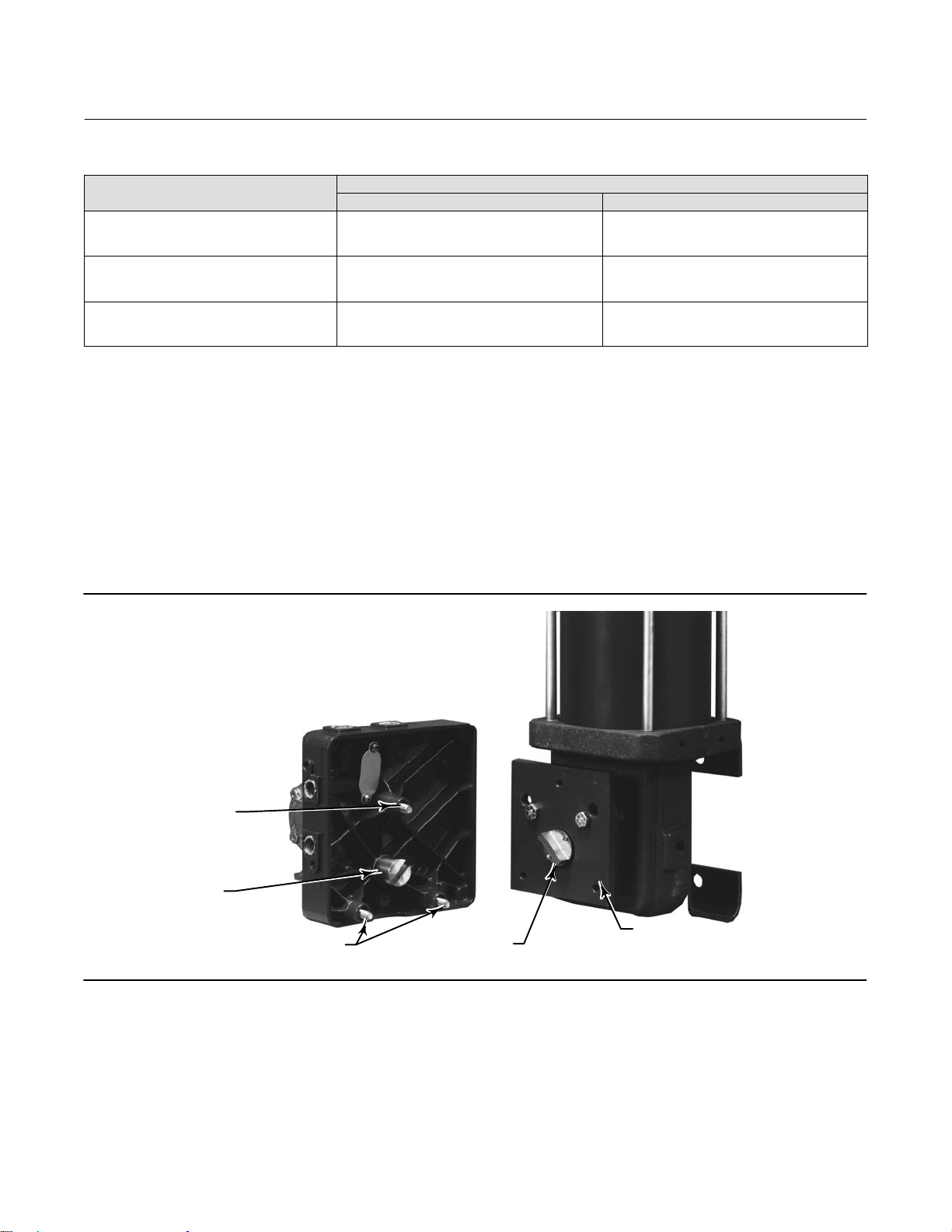
Figure 2 shows a positioner ready for mounting on a piston rotary actuator. A mounting plate (key 43) is used to
mount the positioner base plate to Fisher 1031, 1032, 1051, 1052, 1061, 1066, and 2052 actuators. See table 4 for
actuator sizes.
The positioner also mounts on a Fisher 585 and 585R size 25 or 50 sliding‐stem actuator. A mounting plate (key 43) is
used to mount the positioner base plate to the actuator.
Figure 2. Mounting the Positioner Base Plate
MOUNTING
SCREW
FEEDBACK
SHAFT
POSITIONER
MOUNTING
PLATE (KEY 43)
W6059‐1
MOUNTING SCREWS
TIE BAR
EXTENSION (KEY 44)
5
Page 6

3710 and 3720 Positioners
January 2015
Instruction Manual
D101728X012
Table 4. Positioner to Actuator Mountings
POSITIONER TO ACTUATOR MOUNTINGS
Direct Mounting to Actuator Cover Plate
S1051, size 30
S1052, sizes 30
S1061, size 30, 40, 60, and 68
1. Includes purge tube option.
2. The size 30 actuator is no longer manufactured by Emerson Process Management. 3710 and 3720 positioners are available for field installation on existing size 30 actuators.
(2)
, 40, and 60
(2)
, 40, 60, and 70
(1)
S1031, size 26, 33, 45, 60, and 80
S1032, size 45, 70, 185, 280, 425, 680, 1125, 1370, 2585, and 4580
S1051, size 33
S1052, size 20, 33
S1061, size 80, 100
S1066, size 20, 27, and 75
S2052, size 1, 2, and 3
Mounting Plate Required
Specifications
Specifications are shown in table 1.
Educational Services
For information on available courses for 3710 pneumatic positioners or 3720 electro‐pneumatics positioners, as well
as a variety of other products, contact:
Emerson Process Management
Educational Services, Registration
Phone: +1-641-754-3771 or +1-800-338-8158
e‐mail: education@emerson.com
http://www.emersonprocess.com/education
Installing the 3722 Converter
See figure 3.
WARNING
Avoid personal injury from sudden release of process pressure. Before mounting the 3720 electro‐pneumatic positioner or
3722 electro‐pneumatic converter:
D Wear protective eyewear, gloves and clothing whenever possible.
D Do not remove the actuator from the valve while the valve is still pressurized.
D Disconnect any operating lines providing air pressure, electric power, or a control signal to the actuator. Be sure the
actuator cannot suddenly open or close the valve.
D Use bypass valves or completely shut off the process to isolate the valve from process pressure. Relieve process pressure
on both sides of the valve.
D Relieve any supply or output pressure in the existing positioner.
D When installing an electro‐pneumatic positioner or converter in a hazardous area, turn off control signals until
installation is complete. Be sure all safety barriers, connections, and the converter housing cap and O‐ring are properly
installed before supply a control signal to the unit.
6
Page 7

Instruction Manual
D101728X012
D Use lock‐out procedures to be sure that the above measures stay in effect while you work on the equipment.
D Do not open where an explosive dust atmosphere is present.
D Check with your process or safety engineer for any additional measures that must be taken to protect against process
media.
3710 and 3720 Positioners
January 2015
WARNING
The positioner can provide full supply pressure to any connected equipment. To avoid personal injury and equipment
damage, make sure supply pressure never exceeds the maximum safe working pressure of any connected equipment.
Hazardous Area Classifications and Special Instructions for “Safe Use” and
Installation in Hazardous Locations for 3722 Converter
Note
These Special Instruction for “Safe Use” and Installation in Hazardous Location also apply to 3720 positioners.
Certain nameplates may carry more than one approval, and each approval may have unique installation/wiring
requirements and/or conditions of “safe use”. These special instructions for “safe use” are in addition to, and may
override, the standard installation procedures. Special instructions are listed by approval.
Note
This information supplements the nameplate markings affixed to the product.
Always refer to the nameplate itself to identify the appropriate certification. Contact your Emerson Process Management sales
office for approval/certification information not listed here.
WARNING
Failure to follow these conditions of “safe use” could result in personal injury or property damage from fire or explosion,
and area re‐classification.
CSA
Intrinsically Safe, Explosion-proof, Type n, Dust Ignition-proof
No special conditions for safe use.
Refer to table 5 for approval information.
7
Page 8

3710 and 3720 Positioners
January 2015
Instruction Manual
D101728X012
Table 5. Hazardous Area Classifications for Fisher 3722 Converter
Certification Body Certification Obtained Entity Rating Temperature Code
Intrinsically Safe
Ex ia IIC T4/T5/T6 per drawing GE28591 (figure 34)
Ex ia Intrinsically Safe
Class I, II Division 1 GP A,B,C,D,E,F,G T4/T5/T6
per drawing GE28591 (figure 34)
Explosion-proof
CSA
1. These hazardous area classification also apply to 3720 positioners.
Ex d IIC T5
Class I, Division 1, GP A,B,C,D T5
Type n
Ex nA IIC T6
Class I, Division 2, GP A,B,C,D T6
Class II, Division 1, GP E,F,G T5 T5 (Tamb ≤ 82°C)
Class II, Division 2, GP F,G T6 T6 (Tamb ≤ 82°C)
(1)
—CSA (Canada)
Vmax = 30 VDC
Imax = 150 mA
Pi = 1.25 W
Ci = 0 nF
Li = 0 mH
- - - T5 (Tamb ≤ 82°C)
- - - T6 (Tamb ≤ 82°C)
- - -
T4 (Tamb ≤ 82°C)
T5 (Tamb ≤ 62°C)
T6 (Tamb ≤ 47°C)
T6 (Tamb ≤ 82°C)
FM
Intrinsically Safe, Explosion-proof, Type n, Dust Ignition-proof, Non‐incendive
No special conditions for safe use.
Refer to table 6 for approval information.
Table 6. Hazardous Area Classifications for Fisher 3722 Converter
Certification Body Certification Obtained Entity Rating Temperature Code
Intrinsically Safe
Class I Zone 0 AEx ia IIC T4/T5/T6 per drawing GE28590 (figure 35)
Class I, II, III Division 1 GP A,B,C,D,E,F,G T4/T5/T6
per drawing GE28590 (figure 35)
Explosion-proof
FM
1. These hazardous area classification also apply to 3720 positioners.
Class I Zone 1 AEx d IIC T5
Class I, Division I, GP A,B,C,D T5
Type n
Class I Zone 2 AEx nA IIC T5
Class I, Division 2, GP A,B,C,D T5
Class II, Division 1, GP E,F,G T5
Class II, Division 2, GP F,G T5
(1)
—FM (United States)
Vmax = 30 VDC
Imax = 150 mA
Pi = 1.25 W
Ci = 0 nF
Li = 0 mH
T4 (Tamb ≤ 82°C)
T5 (Tamb ≤ 62°C)
T6 (Tamb ≤ 47°C)
- - - T5 (Tamb ≤ 82°C)
- - - T5 (Tamb ≤ 82°C)
- - - T5 (Tamb ≤ 82°C)
ATEX
Standards Used for Certification
EN 60079-0: 2012 EN 60079-31: 2009
EN 60079-1: 2007 EN 61241-0: 2006
EN 60079-11: 2012 EN 61241-1: 2004
EN 60079-15: 2010 EN 61241-11: 2006
8
Page 9
Instruction Manual
D101728X012
3710 and 3720 Positioners
January 2015
Special Conditions for Safe Use
Intrinsically Safe
This equipment is intrinsically safe and can be used in potentially explosive atmospheres.
The electrical parameters of certified equipment which can be connected to the device must not exceed one of these
following values: U
≤ 30 VDC; I0 ≤ 150 mA; P0 ≤ 1.25 W
0
Ambient temperature: T6, at Tamb = 47_C ; T5, at Tamb = 62_C ; T4, at Tamb = 82_C
Flameproof
The flame path is other than required by EN 60079‐1. Contact the manufacturer for information on the dimensions of
the flameproof joints.
Electrical connections are typically made using either cable or conduit.
D If using a cable connection, the cable entry device shall be certified in type of explosion protection flameproof
enclosure “d”, suitable for the conditions of use and correctly installed.
For ambient temperatures over 70_C, cables and cable glands suitable for at least 90_C shall be used.
D If using a rigid conduit connection, an Ex d certified sealing device such as a conduit seal with setting compound
shall be provided immediately to the entrance of the enclosure.
For ambient temperatures over 70_C, the wiring and setting compound in the conduit seal shall be suitable for at least
90_C.
Type n
No special conditions for safe use.
Refer to table 7 for approval information.
(1)
Table 7. Hazardous Area Classifications for Fisher 3722 Converter
Certification Certification Obtained Entity Rating Temperature Code
II 1 G & D
Intrinsically Safe
Gas
Ex ia IIC T4/T5/T6 Ga
Dust
Ex ia IIIC Da T120 °C (Tamb ≤ 82°C)/T100 °C
(Tamb ≤ 62°C) / T85 °C (Tamb ≤ 47°C)
II 2 G & D
ATEX
1. These hazardous area classification also apply to 3720 positioners.
Flameproof
Gas
Ex d IIC T5 Gb
Dust
Ex tb IIIC T82 °C Db (Tamb ≤ 79°C)
II 3 G & D
Type n
Gas
Ex nA IIC T6 Gc
Dust
Ex tc IIIC Dc T85 °C (Tamb ≤ 82°C)
—ATEX
Ui = 30 VDC
Ii = 150 mA
Pi = 1.25 W
Ci = 0 nF
Li = 0 mH
- - -
- - -
T4 (Tamb ≤ 82°C)
T5 (Tamb ≤ 62°C)
T6 (Tamb ≤ 47°C)
- - -
T5 (Tamb ≤ 82°C)
- - -
T6 (Tamb ≤ 82°C)
- - -
9
Page 10

3710 and 3720 Positioners
January 2015
IECEx
Conditions of Certification
Intrinsically Safe
WARNING
Substitution of components may impair intrinsic safety.
-40_C ≤ Ta ≤ +82_C; T6 (Ta ≤ +47_C); T5 (Ta ≤ +62_C); T4 (Ta ≤ +82_C)
Instruction Manual
D101728X012
Entity Parameters: Ui
30 V, li = 150 mA, Pi = 1.25 W, Ci = 0 nF, Li = 0 mH
=
Flameproof
WARNING
Disconnect power before opening.
-40_C ≤ Ta ≤ +82_C; T5 (Ta ≤ +82_C)
Type n
WARNING
Disconnect power before opening.
-40_C ≤ Ta ≤ +82_C; T6 (Ta ≤ +82_C)
Refer to table 8 for approval information.
(1)
Table 8. Hazardous Area Classifications for Fisher 3722 Converter
Certification Certification Obtained Entity Rating Temperature Code
Intrinsically Safe
Gas
Ex ia IIC T4/T5/T6 Ga
IECEx
1. These hazardous area classification also apply to 3720 positioners.
Flameproof
Gas
Ex d IIC T5 Gb
Type n
Gas
Ex nA IIC T6 Gc
—IECEx
Ui = 30 VDC
Ii = 150 mA
Pi = 1.25 W
Ci = 0 nF
Li = 0 mH
- - - T5 (Tamb ≤ 82°C)
- - - T6 (Tamb ≤ 82°C)
T4 (Tamb ≤ 82°C)
T5 (Tamb ≤ 62°C)
T6 (Tamb ≤ 47°C)
10
Page 11
Instruction Manual
D101728X012
3710 and 3720 Positioners
January 2015
Installation
To change an existing 3710 positioner into a 3720 positioner, install a 3722 electro‐pneumatic converter (figure 3).
The 3722 electro‐pneumatic converter mounts over the input and supply connections of the 3710 positioner.
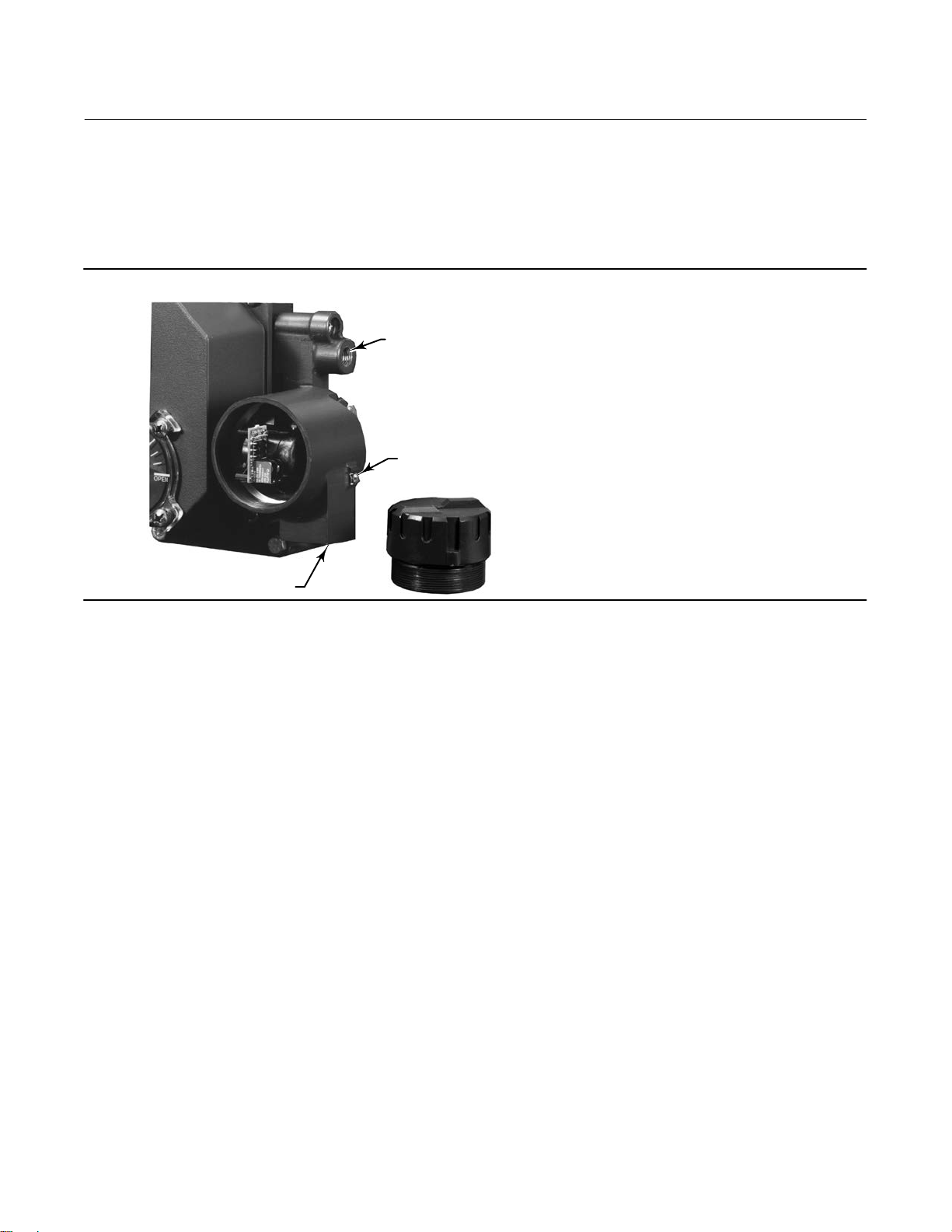
Figure 3. Fisher 3722 Electro‐Pneumatic Converter
SUPPLY CONNECTION
EXTERNAL GROUNDING
SCREW
1/2‐NPT CONDUIT CONNECTION
W6145
1. Be sure all safety procedures have been followed. Remove the input and supply connections from the existing 3710
base plate and clean the ports.
2. Locate the two O‐rings (key 85, figure 32) and properly lubricate (key 82) them. Place one O‐ring in the recessed
area surrounding the input port on the positioner base plate. Place the other O‐ring around the supply port.
3. Locate the two socket head mounting screws (key 84). Properly orient the converter and secure it to the positioner
base plate with the mounting screws. Be sure the O‐rings remain in place while securing the converter to the
positioner base plate.
4. Connect supply pressure to the converter supply port.
Mounting the Positioner
Typically, a positioner is ordered with an actuator. At the factory, the positioner is mounted on the actuator and
calibrated. However, a positioner can be ordered separately and mounted on an existing actuator.
To field‐mount a positioner to an existing actuator, an actuator cover plate with mounting holes and purge tube
knockout may be required. Check the existing actuator cover plate. It must have three positioner mounting holes and,
for specific actuators, a purge tube knockout. See table 4.
11
Page 12

3710 and 3720 Positioners
January 2015
Instruction Manual
D101728X012
If the proper mounting holes are present, perform the following mounting procedure and then follow the calibration
procedures in this instruction manual. Refer to the appropriate instruction manuals for actuator and valve mounting
procedures.
WARNING
Avoid personal injury from sudden release of process pressure. Before mounting the 3720 electro‐pneumatic positioner or
3722 electro‐pneumatic converter:
D Wear protective eyewear, gloves and clothing whenever possible.
D Do not remove the actuator from the valve while the valve is still pressurized.
D Disconnect any operating lines providing air pressure, electric power, or a control signal to the actuator. Be sure the
actuator cannot suddenly open or close the valve.
D Use bypass valves or completely shut off the process to isolate the valve from process pressure. Relieve process pressure
on both sides of the valve.
D Vent the power actuator loading pressure and relieve any actuator spring precompression.
D Use lock‐out procedures to be sure that the above measures stay in effect while you work on the equipment.
D When installing a positioner or converter in a hazardous area, turn off control signals until installation is complete. Be
sure all safety barriers, connections, and the converter housing cap and O‐ring are properly installed before supplying a
control signal to the unit.
D Check with your process or safety engineer for any additional measures that must be taken to protect against process
media.
WARNING
The positioner can provide full supply pressure to any connected equipment. To avoid personal injury and equipment
damage, make sure supply pressure never exceeds the maximum safe working pressure of any connected equipment.
Note
The positioner mounts directly to the actuator cover plate of several Fisher actuators. See table 4. To directly mount the positioner
to an existing Fisher actuator, you must use an actuator cover plate with three positioner mounting holes and the 5/8‐inch purge
option knockout plug.
See the parts list for the specific actuator cover plate required above to integrally mount the positioner.
See figures 4 and 33 for positioner mounting drawings.
Note
To mount the positioner to an actuator with an existing Fisher 3610 positioner, remove the 3610 positioner and replace it with an
appropriate metal cover plate and four cap screws. For assistance, contact your Emerson Process Management sales office.
12
Page 13
Instruction Manual
D101728X012
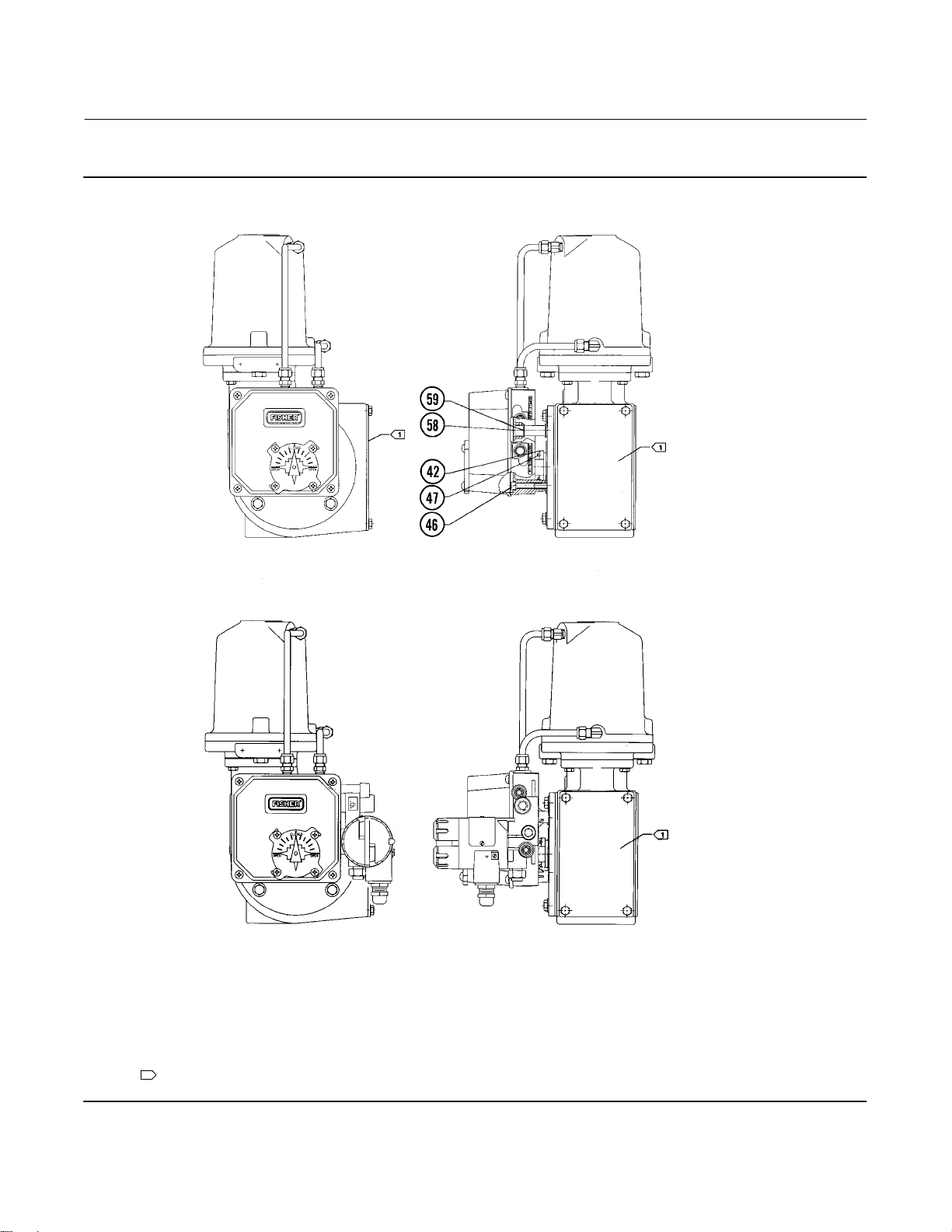
Figure 4. Typical Positioner/Actuator Combinations
3710 and 3720 Positioners
January 2015
42B8466‐A
3710 POSITIONER MOUNTED ON A
1061 SIZE 30 ACTUATOR
42B8466‐A
3720 POSITIONER MOUNTED ON A
1061 SIZE 30 ACTUATOR
NOTES:
FIGURE 33 SHOWS ADDITIONAL POSITIONER/ACTUATOR COMBINATIONS
1
ACTUATOR COVER PLATE REQUIRED WHEN REPLACING AN INSTALLED 3610 POSITIONER
13
Page 14

3710 and 3720 Positioners
January 2015
Instruction Manual
D101728X012
1. See figure 5 for a typical actuator. Remove the actuator travel indicator machine screws, travel indicator, and
actuator cover cap screws.
Note
When removing the actuator cover plate, take care not to change the position of the rod end bearing on the end of the turnbuckle
inside the actuator housing.
2. If necessary, install a new cover plate.
a. Remove the existing cap screws and actuator cover plate from the actuator housing.
b. Remove the retaining ring (e‐clip) and hub from the cover plate.
c. Install the hub and retaining ring into the new actuator/positioner cover plate.
Note
Position the actuator cover plate so the positioner mounting holes on the new cover plate allow placement of the positioner in the
desired orientation.
Actuator cover alignment on the 1052 actuator can be aided by moving the actuator slightly away from its “up” travel stop using a
regulated air source. If the hole alignment cannot be obtained in this manner, temporarily loosen the cap screws that secure the
housing to the mounting yoke and shift the housing slightly. Do not completely travel the actuator while the cover is removed.
Tighten the actuator cap screws before continuing.
3. Position the new actuator/positioner cover plate so the positioner mounting holes on the new cover plate allow
placement of the new positioner in the desired orientation. Secure the new cover plate to the actuator.
4. Install the positioner tie bar (key 42) in place of the travel indicator on the actuator hub.
Note
Before installation of the positioner mounting plate (key 43), review the mounting drawings (figures 4 and 33). Properly align the
positioner mounting plate before attaching the mounting plate to the actuator cover plate. Note that the three positioner
mounting holes must be aligned to match the three mounting screws which will pass through the base of the positioner.
5. If the specific actuator requires a positioner mounting plate (key 43), install the mounting plate using the cap
screws (key 45).
6. Unscrew the four captive cover screws and remove the cover assembly (key 7) from the positioner.
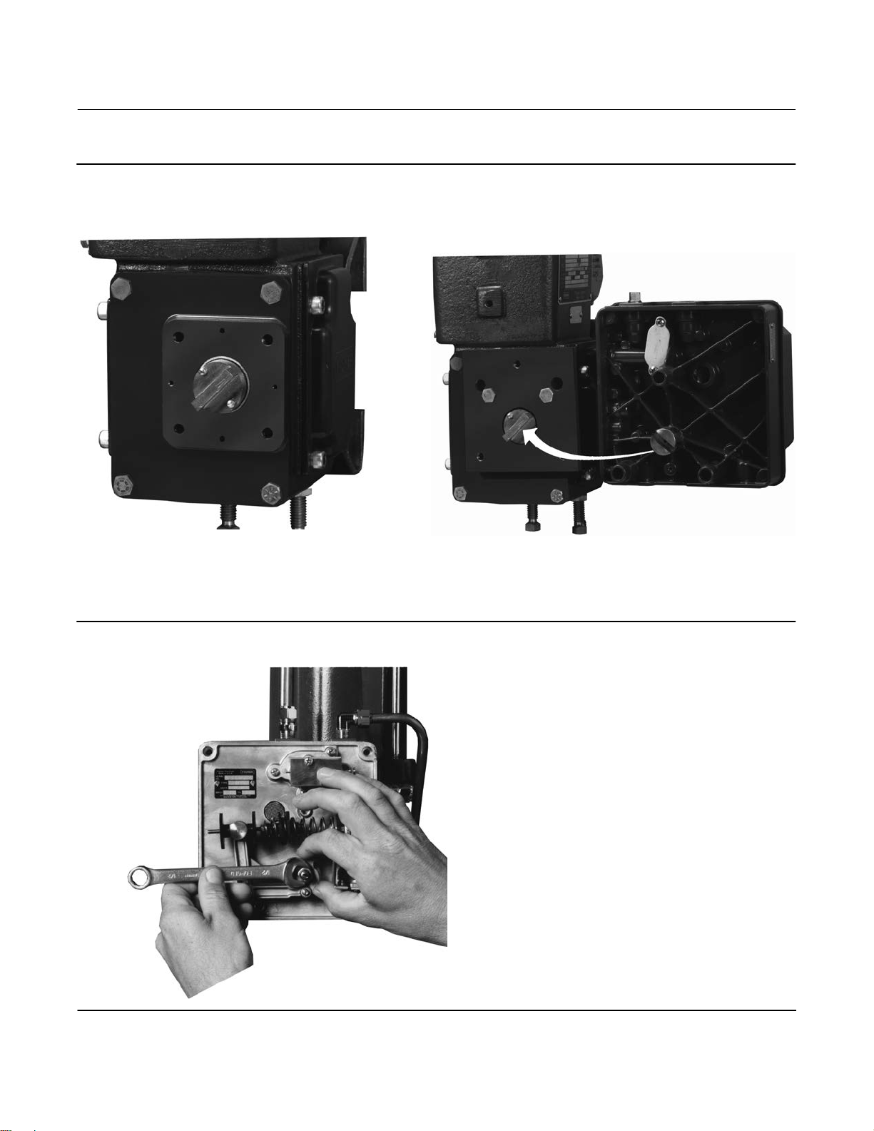
7. See figure 6. Loosen the cam locknut (key 37) and rotate the feedback shaft (key 38) as necessary to align the slot in
the feedback shaft end with the tie bar on the actuator hub. Tighten the cam locknut.
8. Align the positioner with the mounting holes in the new actuator cover plate or positioner mounting plate. Be sure
that the tie bar fits securely into the feedback shaft end slot. Secure the positioner to the actuator cover plate or
mounting plate using the (hex) socket head cap screws (key 46).
9. Before installing the positioner cover, properly align the valve position indicator (standard, low‐profile indicator or
optional beacon indicator). Follow the standard or beacon indicator alignment procedure given in this instruction
manual. Then, install the positioner cover assembly.
14
Page 15
Instruction Manual
D101728X012
Figure 5. Typical Piston Actuator (Fisher 1061)
3710 and 3720 Positioners
January 2015
W6147‐1
TIE BAR, MOUNTING PLATE REMOVED
Figure 6. Loosening the Cam Locknut
W6146‐1
REAR VIEW, POSITIONER BASE PLATE, AND MOUNTING AREA
W5916
15
Page 16
3710 and 3720 Positioners
January 2015
Instruction Manual
D101728X012
Installing the 3710 or 3720 Pneumatic Positioner on Size 25 or 50 585 and
585R Actuators
Refer to figures 7, 8, and 9 for key number locations unless noted otherwise.
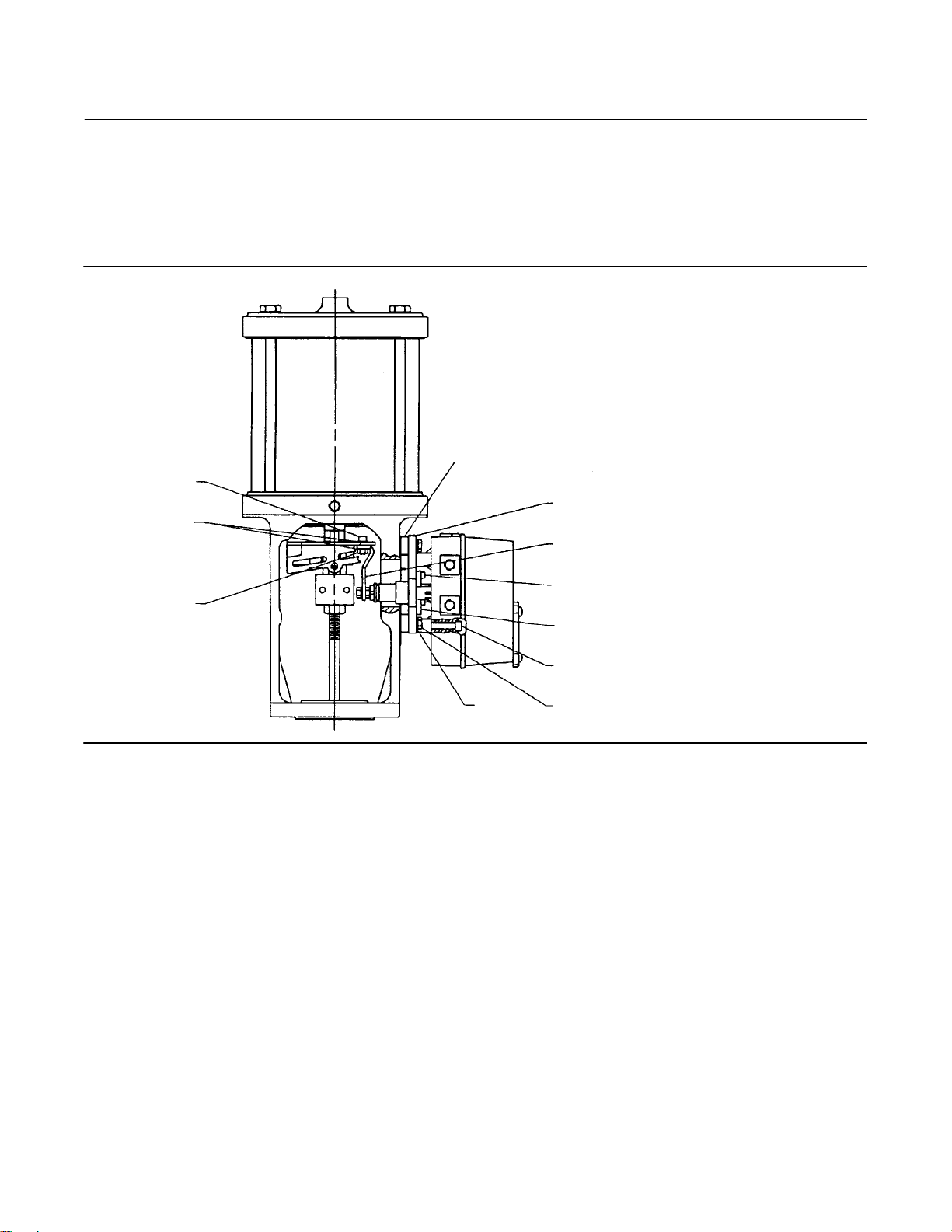
Figure 7. Typical Fisher 3710 Positioner Mounted on a 585 Actuator
SPACER
CAP SCREW
(KEY 99)
LOCK WASHER
(KEY 100)
(KEY 61)
MOUNTING PLATE
(KEY 43)
DRIVE STUD BRACKET
(KEY 98)
CAP SCREW
HEX NUT
(KEY 96)
LOCK
WASHER
(KEY 92)
(KEY 93)
MOUNTING BEARING
(KEY 97)
CAP SCREW
(KEY 46)
CAP SCREW
KEY 45
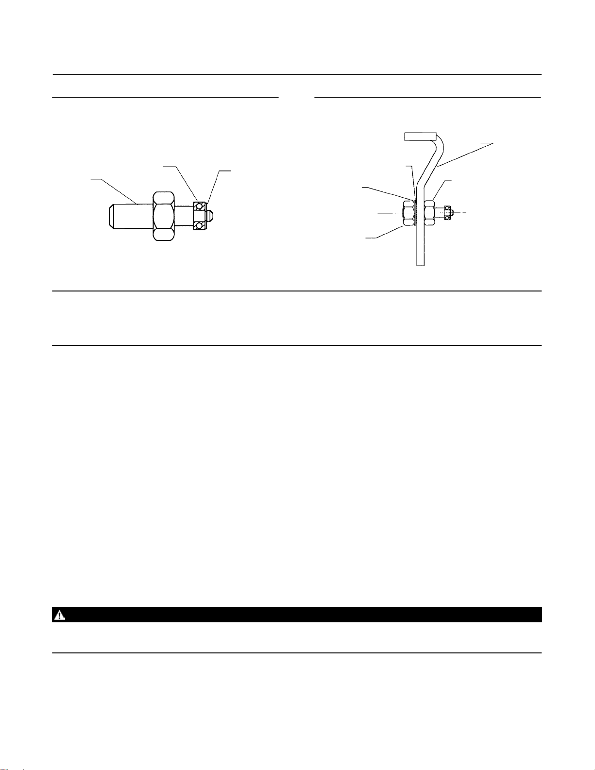
1. An actuator stem bracket is supplied with the positioner. Assemble the various positioner feedback parts to the
stem bracket as follows:
a. Refer to figure 8. Install the roller bearing (key 101) on the drive stud (key 95) and secure with the E‐ring
(key 102).
b. Refer to figure 9. Attach the drive stud (with roller bearing) to the drive stud bracket (key 98) with 1/4‐inch hex
nut (key 96), lock washer (key 100), and flat washer (key 103). Place the flat washer between the lock washer and
the hex nut. The washers and hex nut should all be on the same side of the drive stud bracket as shown in figure
9. The flat washer may be moved to the other side of the drive stud (between the drive stud and the drive stud
bracket) if extra space is required to position the roller bearing near the center of the feedback lever. Leave the
hex nut loose for later adjustment.
c. Attach the drive stud bracket (with drive stud) to the actuator stem bracket using two cap screws (key 99), two
lock washers (key 100), and two hex nuts (key 96). Leave the hex nuts loose for later adjustment.
2. Stroke the actuator from the top stop to the bottom stop, and record the travel.
In steps 3 through 6, refer to the actuator instruction manual for key number locations unless noted otherwise.
3. Loosen eight screws, and remove the front and back yoke covers (keys 18 and 20).
4. Loosen the two cap screws in the stem connector assembly (key 15) and remove the stem connector. Separate the
actuator piston stem (key 12) from the valve plug stem.
16
Page 17
Instruction Manual
D101728X012
3710 and 3720 Positioners
January 2015
Figure 8. Drive Stud and Roller Bearing Assembly
Figure 9. Drive Stud Bracket with Drive Stud and
Roller Bearing Assembly
DRIVE STUD BRACKET
ROLLER BEARING
DRIVE STUD
(KEY 95)
Note
Before performing the next step, position the valve plug stem at the lower end of its travel. Position the actuator stem at the upper
travel stop. Check for sufficient clearance between the actuator stem and the valve stem to allow removing the stem bracket
assembly. If there is insufficient clearance, remove the actuator from the valve.
(KEY 101)
E‐RING
(KEY 102)
FLAT WASHER
(KEY 1103)
HEX NUT
(KEY 96)
LOCK
WASHER
(KEY 100)
(KEY 98)
DRIVE STUD
AND ROLLER BEARING
5. Loosen the stem bracket retainer (key 14) and let it slide down over the valve plug stem. Remove the stem bracket
assembly (key 13).
6. Install the stem bracket assembly (with drive stud and drive stud bracket) on the actuator stem. Align the stem
bracket assembly so that it will be parallel with the back yoke cover. Install the stem bracket retainer and tighten to
68 NSm (50 lbfSft). If the actuator was removed from the valve, install the actuator on the valve. Do not attach the
stem connector at this time.
7. Attach the mounting bearing (key 97) to the mounting plate (key 43) with three hex socket cap screws (key 93).
8. Refer to the actuator instruction manual. Loosen the four screws, and remove the actuator blanking plate.
9. Attach the positioner mounting plate to the actuator yoke as shown in figure 10 with four spacers (keys 61), four
cap screws (key 45) and lock washers (key 92).
10. Loosen the four captive cover screws and remove the positioner cover.
11. Loosen the cam locknut (key 37, figure 31).
12. Attach the positioner to the mounting plate with three hex socket cap screws (key 46). Make sure that the
positioner feedback shaft (key 38, figure 31) rotates freely and is not binding with the mounting bearing, adjust if
necessary.
13. Attach the feedback lever (key 94) to the end of the feedback shaft with the two hex socket cap screws (key 93).
The markings on the feedback lever should be visible when looking toward the back of the positioner. Make sure the
roller bearing (key 101) on the drive stud engages the slot in the feedback lever.
WARNING
An unexpected change in actuator supply pressure while performing the following steps could result in personal injury. Use
lockout procedures to ensure a stable air supply.
14. Perform the Actuator Mounting procedure steps 2 through 8 in the actuator instruction manual to reconnect the
actuator stem and valve stem.
17
Page 18

3710 and 3720 Positioners
January 2015
Instruction Manual
D101728X012
15. Make sure the cam locknut (key 37, figure 31) is loose, then stroke the valve/actuator to mid‐travel. Adjust the drive
stud location vertically so that the feedback lever is perpendicular to the stem. Tighten the hex nut attached to the
drive stud.
16. Refer to figure 11. Adjust the position of the drive stud bracket so that the center of the roller bearing aligns with
the appropriate travel mark on the feedback lever.
17. Tighten the cap screws to secure the drive stud bracket to the stem bracket. If necessary, readjust the drive stud
position to keep the feedback lever perpendicular to the stem.
18. Make the output, supply, instrument, and vent connections as described in the Connection section. Calibrate the
positioner by performing the procedures in the Calibration section.
19. Replace the actuator front and back yoke covers. Discard the actuator blanking plate and four screws.
Figure 10. Mounting Plate Positioned on Actuator
W8461
Figure 11. Positioning Drive Stud in Feedback Lever
FEEDBACK LEVER
(KEY 94)
DRIVE STUD
AND ROLLER BEARING
Connections
WARNING
The positioner is capable of providing full supply pressure to connected equipment. To avoid personal injury and
equipment damage, make sure the supply pressure never exceeds the maximum safe working pressure of any connected
equipment.
To complete the installation of a positioner, connect tubing and fittings between the positioner and the actuator. The
fittings, tubing, and mounting parts required depend on the type number and optional equipment such as filter,
regulator, and bypass valve.
Positioner pressure and electrical connection locations are shown in figure 12. All pressure connections are 1/4 NPT
internal. Use 3/8‐inch tubing or 1/4 NPT pipe for all tubing connections.
18
Page 19

Instruction Manual
D101728X012
Figure 12. Connections
OUTPUT CONNECTIONS
3710 and 3720 Positioners
January 2015
INPUT (SUPPLY)
CONNECTION
RIGHT SIDE VIEW
34B0693‐A
B2386‐1
TOP VIEW
INPUT
CONNECTIONS
3710 POSITIONER
REAR VIEW
VENT
OPENING
M20 CABLE
GLAND
RIGHT SIDE VIEW
3720 POSITIONER
VENT
The conduit connection to the converter is 1/2‐14 NPT.
The positioner does not have a remote vent connection. Refer to the section on vent opening, purge option, and
actuator vent connection for instructions about a remote vent connection.
Supply Connection
WARNING
Severe personal injury or property damage may occur if the instrument supply medium is not clean, dry and oil‐free. While
use and regular maintenance of a filter that removes particles larger than 40 micrometers in diameter will suffice in most
applications, check with an Emerson Process Management field office and industry instrument air quality standards for use
with corrosive gas or if you are unsure about the proper amount or method of air filtration or filter maintenance.
3720 positioners and 3722 converters do not meet third party approvals for use with natural gas as the supply pressure
medium. Use of natural gas as the supply medium can result in personal injury or property damage from fire or explosion.
See figure 12.
Connect a clean, dry, oil‐free, noncorrosive air source to the supply connection of the positioner. Recommended
supply line size is 3/8‐inch tubing or 1/4 NPT pipe. Use of an appropriate supply air filter or filter regulator is
recommended. Refer to the positioner specifications, table 1, for supply pressure requirements.
19
Page 20

3710 and 3720 Positioners
January 2015
Supply pressure must not exceed the following limits:
D For the positioner, do not exceed the maximum pressure rating of 10.3 bar (150 psig).
D For actuator pressure, refer to the appropriate actuator instruction manual for maximum allowable pressures.
D For the valve body assembly, do not exceed the maximum allowable torque or thrust of the specific valve.
Instruction Manual
D101728X012
Output Connections
See figure 12.
Use 3/8‐inch tubing between the actuator and positioner.
For diaphragm rotary actuators (single‐action output from the positioner): Plug OUTPUT A. Connect OUTPUT B to the
diaphragm casing connection.
For piston rotary actuators (double‐action output from the positioner): To extend the actuator stem with increasing
instrument input signal, connect OUTPUT A to the lower actuator cylinder connection and OUTPUT B to the upper
actuator cylinder connection. To retract the actuator stem with increasing instrument input signal, connect OUTPUT A
to the upper actuator cylinder connection and OUTPUT B to the lower actuator cylinder connection.
Instrument Connection
See figure 12.
Use 3/8‐inch tubing to connect the output from the control device to the INSTRUMENT connection on a pneumatic
positioner. For the electro‐pneumatic positioner, refer to the Electrical Connection section.
Vent Opening, Purge Option, and Actuator Vent Connection
WARNING
Personal injury or property damage could result from fire or explosion of the accumulated gas if a flammable gas is used as
the supply pressure medium. Personal injury or property damage could also result from contact with the hazardous gas.
The 3710 positioner/actuator assembly does not form a gas‐tight seal and flammable or hazardous gas could leak from the
assembly. Therefore, if the assembly is enclosed, install a remote vent line from the enclosure. However, a remote vent
pipe from the enclosure alone cannot be relied upon to remove all hazardous gas. Use adequate ventilation and other
necessary safety measures. Vent line piping should comply with local and regional codes and should be as short as possible
with adequate inside diameter and few bends to reduce case pressure buildup.
WARNING
3720 and 3722 do not meet third party approvals for use with natural gas as the supply pressure medium. Use of natural
gas as the supply medium can result in personal injury or property damage from fire or explosion.
See figure 13.
20
Page 21

Instruction Manual
D101728X012
Figure 13. Mounting the Positioner Base Plate with Purge Tube
PURGE TUBE
(KEY 58)
O‐RINGS (KEY 59)
3710 and 3720 Positioners
January 2015
LONG‐BLADED SCREW
DRIVER THROUGH VENT
W6073
The positioner does not have an external vent connection. A unit exhausts actuator pressure through a screened hole
(vent opening, figure 12) located in the positioner base plate. Do not restrict the vent opening. Restricting the vent
opening can produce a pressure buildup in the positioner case and degrade positioner performance.
A purge tube (key 58, figure 13) is available as an option when mounting the positioner on selected Fisher actuators.
One end of the purge tube with an O‐ring (key 59) installs in the actuator cover plate. The other end of the purge tube
with an O‐ring installs in the vent opening in the positioner base plate. When the purge tube is used, it relays actuator
exhaust pressure from the positioner into the actuator housing.
Within the actuator and positioner assembly, exhaust pressure takes the following course:
D The actuator exhaust pressure vents from the actuator through the positioner spool valve into the positioner
case.
D The exhaust pressure then exits the positioner case through the vent opening.
D The purge tube carries the exhaust pressure into the actuator housing.
D The exhaust pressure then purges the actuator housing and dissipates from the housing.
Most Fisher actuators do not have vent openings. The exhaust pressure simply dissipates from within the actuator
housing. However, the 1051, 1052, and 1061 actuators feature an operational screened vent connection when a
metal access plate is specified for the actuator housing.
When using the purge option, remember: The actuator and positioner assembly is not airtight. However, if you use the
optional purge tube to connect the positioner to the actuator and the actuator has a vent opening, leave open the 1/4
NPT vent connection in the actuator housing to prevent pressure buildup in the positioner case.
21
Page 22

3710 and 3720 Positioners
January 2015
Instruction Manual
D101728X012
If the 1/4 NPT vent connection is available, a vent line can be installed from the actuator. However, the
valve/actuator/positioner assembly is not airtight. Maintain adequate ventilation and observe other safety measures.
For help in selecting the purge option for positioner/ actuator combinations, contact your Emerson Process
Management sales office.
Connecting the Purge Tube
The positioner mounts directly to the actuator cover plate of 1051, 1052, and 1061 actuators. See table 4 for actuator
sizes.
With an integral mounting, a purge tube (key 58), with two O‐rings (key 59), can be used to relay actuator exhaust
pressure from the positioner into the actuator housing. If the current actuator cover plate does not have the positioner
mounting holes and purge tube knockout, order a new cover plate. See the parts list for the specific actuator cover
plate required for each actuator.
1. The actuator cover plate features a purge tube knockout. Locate the knockout and use appropriate tools to open
this hole in the cover plate.
2. Install the actuator cover plate and then insert the purge tube with O‐ring into the purge tube hole in the cover
plate.
Note
When mounting a positioner to an actuator with the purge tube installed, guide the purge tube into the vent opening in the
positioner base plate by removing the vent screen (key 41) and then inserting an appropriate tool such as a screwdriver through
the vent opening into the purge tube.
When the positioner is secured to the actuator, install the vent screen.
3. Before mounting the positioner, be sure the second O‐ring is properly fitted to the end of the purge tube. Use care
when mounting the positioner. Be sure the purge tube with O‐ring fits into the vent opening on the rear of the
positioner base plate.
4. Secure the positioner to the mounting plate using the (hex) socket head cap screws (key 46).
5. Install the vent screen in the positioner base plate.
Electrical Connection for the 3720 Positioner
WARNING
In explosion‐proof applications, disconnect power before removing the converter housing cap.
In Class I, Division 1 explosion‐proof applications, install rigid metal conduit and a conduit seal no more than 457 mm
(18 inches) from the converter. Personal injury or property damage may result from explosion if the seal is not installed.
For intrinsically‐safe installations, refer to the loop schematics shown in figures 34 and 35 or to instructions provided by the
barrier manufacturer for proper wiring and installation.
Select wiring and/or cable glands that are rated for the environment of use (such as hazardous area, ingress protection and
temperature). Failure to use properly rated wiring and/or cable glands can result in personal injury or property damage
from fire or explosion.
Wiring connections must be in accordance with local, regional, and national codes for any given hazardous area approval.
Failure to follow the local, regional, and national codes could result in personal injury or property damage from fire or
explosion.
22
Page 23

Instruction Manual
D101728X012
3710 and 3720 Positioners
January 2015
Use the 1/2‐14 NPT conduit connection for field wiring installation. Refer to figures 14 and 15 when connecting field
wiring from the control device to the converter. Connect the positive wire from the control device to the converter's
positive ( + ) terminal and the negative wire from the control device to the converter's negative ( ‐ ) terminal.
Do not overtighten the terminal screws. Maximum torque is 0.45 Newton‐meters (0.45 NSm) or 4 pounds force per
inch (4 lbfSin).
Figure 14. Field Wiring Diagram
CONVERTER MODULE
TERMINAL BLOCK
FIELD WIRING
INDICATING DEVICE
1
GROUNDING
2
SCREW
NOTES:
FOR TROUBLESHOOTING OR MONITORING OPERATION THE INDICATING
1
DEVICE CAN BE A VOLTMETER ACROSS A 250 OHM RESISTOR OR CURRENT METER
THE 3722 CONVERTER HOUSING FEATURES INTERNAL AND EXTERNAL
2
GROUNDING SCREWS
EARTH SCREW
Diagnostic Connections
See figure 16.
Figure 15. Circuit Schematic
4-20 mA
5.6 V 5.6 V5.6 V
60 OHMS
60 OHMS
For diagnostic testing of control valve packages (valve, actuator, positioner, and accessories), special connectors and
hardware are available. The hardware required for diagnostic connections includes 3/4 NPT pipe nipples and pipe tees
with a
1/8 NPT pipe bushing for the connector. The connector consists of a 1/8 NPT body and body protector. If the
diagnostic connectors are ordered for a positioner with gauges, 1/8‐inch stems are also included.
Install connectors and hardware between the positioner and the actuator.
1. Before assembling the pipe nipple, pipe tee, pipe bushing, actuator piping, and connector body, apply sealant
(key 64) to all threads.
2. Assemble connectors and hardware. Remove standard piping connections, if necessary, and install the diagnostic
connections.
D 3720: For a diagnostic connection to the instrument pressure output from the converter module, remove the 1/8
NPT pipe plug (key 86) from the 3722 converter housing. Apply sealant (key 83) to the threads of the 1/8 NPT
connector body and install it directly into the housing.
D 3710, 3720: For diagnostic connections made up of a pipe nipple, pipe tee, pipe bushing, and connector body,
turn the pipe tee to position the connector body for easy access when doing diagnostic testing.
23
Page 24

3710 and 3720 Positioners
January 2015
Instruction Manual
D101728X012
Figure 16. Diagnostic Connections
PIPE NIPPLE
OUTPUT “B”
NOTE:
REMOVE PIPE PLUG,
1
THEN INSTALL CONNECTOR BODY
13B8743‐A
B2414
PIPE NIPPLE
OUTPUT “A”
3710
3722
3720 POSITIONER
STEM PROVIDED WHEN
GAUGE IS SPECIFIED
PIPE NIPPLE
SUPPLY
CONNECTOR BODY
TO INSTRUMENT
GAUGE
BODY PROTECTOR
BODY
PIPE BUSHING
PIPE TEE
1
PIPE NIPPLE
OUTPUT “B”
24
12B8055‐A
B2385
PIPE NIPPLE
OUTPUT “A”
PIPE NIPPLE
SUPPLY
3710
GAUGE
STEM PROVIDED
WHEN GAUGE IS SPECIFIED
BODY PROTECTOR
BODY
PIPE BUSHING
PIPE TEE
PIPE
NIPPLE INSTR.
3710 POSITIONER
Page 25

Instruction Manual
D101728X012
3710 and 3720 Positioners
January 2015
Calibration
The following calibration procedures are for the 3710 pneumatic positioner adjustment. For the 3720
electro‐pneumatic positioner, there are no adjustments within the 3722 converter portion of the positioner. All
adjustments are accomplished within the pneumatic portion of the positioner.
WARNING
During calibration the valve will move. To avoid personal injury or property damage caused by the release of pressure or
process fluid, provide some temporary means of control for the process.
Setting the Initial Cam Position
Before trying any calibration procedure, follow these instructions to position the cam (key 36) with respect to the valve
position.
1. Unscrew the four captive cover screws (key 8) and remove the positioner cover assembly (key 7).
2. See figure 17. Inspect the cam (key 36) and loosen the cam locknut (key 37).
3. Disconnect the positioner output tubing at the actuator and attach a regulated air source or other means of
positioning the actuator.
4. Position the actuator to correspond with the initial valve position at minimum instrument input signal. Stroke the
actuator to the final valve position and note the direction of actuator shaft rotation. Return the actuator to its initial
valve position.
5. See figure 18. Position the cam on the roller for the desired input signal range, for example, 0-100%, and insure that
the arrow on the cam corresponds with the direction of actuator shaft rotation for increasing input signal. Tighten
the cam locknut, leaving a gap of approximately 0.80 mm (0.031 inches) between the cam and roller. Tighten the
cam nut to 3.8 to 9.1 nSm (30 to 75 lbfSin).
6. Reconnect the output tubing to the actuator.
Figure 17. Loosening the Cam Locknut
W5916
Figure 18. Proper Cam Position
0.8 mm
(0.031 INCH)
A6045
25
Page 26

3710 and 3720 Positioners
January 2015
Zero and Span Adjustments
See figure 19.
Figure 19. Features and Adjustments
1
SPAN ADJ ASSY
2
NAMEPLATE
AREA
SCREENED
VENT OPENING
ZERO ADJ PIVOT
SPAN ADJ SHAFT
(THREADED ROD)
ACTION BLOCK
Instruction Manual
D101728X012
MOUNTING SCREW HOLE
SPOOL VALVE
INPUT MODULE
ZERO ADJUSTER
LOCK NUT
ZERO ADJUSTER
FEEDBACK
ARM ASSY
NOTES:
1
THE SPAN ADJ ASSY IS MADE UP OF THE RANGE SPRING, SPAN ADJ SHAFT (THREADED ROD), AND SPAN ADJ KNOB.
2
THE SPAN ADJ ASSY FEATURES A RED COLOR‐CODED RANGE SPRING FOR A 6 TO 30 PSIG INPUT SIGNAL
W5947
MOUNTING
SCREW HOLE
CAM
SUMMING BEAM ASSEMBLY
SUMMING BEAM FLEXURE
MOUNTING SCREW HOLE
1. To start this procedure, if necessary, unscrew the four captive cover screws (key 8) and remove the cover assembly
(key 7).
2. Apply supply pressure.
3. Provide a way to check the input signal. Apply the minimum input signal. For example:
D For a 3710 pneumatic positioner, if the input signal range is 0.2 to 1.0 bar (3 to 15 psig), apply 0.2 bar (3 psig).
D For a 3720 electro‐pneumatic positioner, if the input signal range is 4-20 mA, apply 4 mA to the 3722 converter.
Note
The zero adjustment locknut and zero adjustment knob are identical parts, key 35.
4. Loosen the zero adjustment locknut (key 35) and turn the zero adjustment knob (key 35) until the actuator moves
the valve to the proper position. This valve position must correspond to the minimum input signal.
26
Page 27

Instruction Manual
D101728X012
3710 and 3720 Positioners
January 2015
Tighten the zero adjustment locknut before proceeding to step 5.
5. Slowly increase the input signal until the input reaches the maximum input signal. Observe the actuator travel and
valve position as the input increases. Determine the actuator/valve position at the maximum input signal.
6. After observing the actuator/valve travel at maximum input signal, return the input signal to the minimum input
signal before turning the span adjustment knob.
D If the actuator/valve travel, observed in step 5, stopped short of the required valve position at maximum input
signal, increase the actuator/valve travel by rotating the positioner span adjustment knob toward the zero
adjustment nut (key 35) to add active spring coils to the range spring.
D If the actuator/valve travel, observed in step 5, reaches the required valve position before the input signal
reaches the maximum input signal, decrease the actuator/valve travel by rotating the positioner span
adjustment knob away from the zero adjustment nut (key 35) to remove active spring coils from the range
spring.
7. After turning the span adjustment knob to change actuator travel, re‐zero the positioner using the procedure given
in steps 4 and 5, above.
Note
The outputs of a properly calibrated positioner will be in the saturated condition (zero pressure or full supply) when the valve is
fully open or closed.
8. Increase the input signal until the input reaches the maximum input signal. Observe the actuator/valve travel as the
input increases.
Repeat steps 3 through 8 until the actuator travel corresponds to the input signal range.
9. Properly align the indicator and replace the positioner cover assembly.
Standard or Beacon Indicator Alignment
Note
The standard, low‐profile indicator consists of the indicator cover (key 14), indicator (key 15) with internal retaining ring (e‐clip)
(key 12), and separate pointer (key 13) recessed into the indicator. An O‐ring (key 15A) fits over the molded screwdriver slot in the
indicator to retain the pointer.
The optional beacon indicator consists of an external unit (key 10) with external retaining ring (key 12) and extension shaft
(key 11).
See figure 20.
1. Locate the indicator/extension shaft (key 11 or key 15) inside the front cover. To align the indicator, rotate the
indicator/extension shaft to match the position of the feedback shaft extending from the cam (key 36).
2. Install the cover assembly (key 7) so that the indicator/extension shaft joins with the feedback shaft. The standard
indicator (key 15) features a molded screwdriver slot that protrudes through the indicator cover (key 14). If
necessary, use a small, Phillips head screwdriver to align the indicator with the feedback shaft.
27
Page 28

3710 and 3720 Positioners
January 2015
Figure 20. Standard Indicator
2
FEEDBACK SHAFT
(CAM SHAFT) (KEY 38)
NOTES:
1RETAINING RING (E‐CLIP) (KEY 12) IS NOT SHOWN.
2THE SHAFT OF THE INDICATOR (KEY 15) PASSES THROUGH THE POSITIONER COVER AND FITS OVER THE END OF THE FEEDBACK SHAFT (CAM SHAFT) (KEY 38).
W6061
1
INDICATOR (KEY 15)
INDICATOR SCALE (KEY 14)
Instruction Manual
D101728X012
3. Inspect the indicator, pointer, and scale. Make sure the proper valve position is shown. Follow the procedures given
in this instruction manual to move the valve from fully opened to fully closed. Make sure the indicator properly
displays the valve position.
If the indicator is not properly aligned, continue with the following procedure.
4. If the indicator pointer and indicator scale are slightly out of alignment, loosen the four machine screws (key 3) that
hold the indicator scale to the positioner cover. Turn the scale to properly align it with the pointer. Tighten the four
screws and move the valve to confirm proper valve position indication.
5. If the pointer in the standard, low‐profile indicator is positioned in the wrong quadrant, loosen the four machine
screws (key 8) that hold the indicator scale (key 14) to the positioner cover. Remove the indicator scale. Then,
carefully lift the pointer (key 13) from the indicator (key 15). Place the pointer in the proper position and re‐install
the indicator scale, and screws. Make sure the indicator scale and pointer are now properly aligned by moving the
valve. If sufficient adjustment is not available in the scale, the actuator might be installed incorrectly.
6. If the internal scale of the beacon indicator is not properly aligned, remove the four machine screws that hold the
beacon indicator (key 10) to the positioner cover. Properly orient the beacon cover and replace the screws. Make
sure the beacon cover and scale are now properly aligned by moving the valve.
Changing Positioner Action
WARNING
Avoid personal injury or equipment damage from sudden release of process fluid. Before changing positioner action:
D Wear protective eyewear, gloves, and clothing whenever possible.
D Do not remove the actuator from the valve while the valve is still pressurized.
D Disconnect any operating lines providing air pressure, electric power, or a control signal to the actuator and
accessories. Be sure the actuator cannot suddenly open or close the valve.
D Use bypass valves or completely shut off the process to isolate the valve from process pressure. Relieve process pressure
on both sides of the valve.
28
Page 29

Instruction Manual
D101728X012
D Vent the actuator loading pressure.
D Use lock‐out procedures to be sure that the above measures stay in effect while you work on the equipment.
D Check with your process or safety engineer for any additional measures that must be taken to prevent against process
media.
3710 and 3720 Positioners
January 2015
Single‐Acting/Double‐Acting
See figure 21 for positioner output connections. See figure 23 for the positioner schematic.
Figure 21. Output Connections
OUTPUT CONNECTIONS
A6056
TOP VIEW
Use 3/8‐inch tubing between the positioner and actuator.
D For single‐acting output, plug positioner OUTPUT A. Refer to the actuator instruction manual for the specific
connection for positioner OUTPUT B. Connect positioner OUTPUT B to the actuator connection for single‐acting.
For Fisher diaphragm actuators, this connection is known as the diaphragm casing connection.
D For double‐acting output (with direct‐action), refer to the actuator instruction manual for the specific
connections for positioner OUTPUT A and B. Connect positioner OUTPUT A to the actuator cylinder connection
where actuator air pressure is exhausted during the initial actuator stroke. Connect positioner OUTPUT B to the
actuator cylinder connection where supply pressure enters the actuator during the initial actuator stroke. For
Fisher piston actuators, OUTPUT A connects to the lower actuator cylinder connection and OUTPUT B connects
to the upper actuator cylinder connection.
Direct‐Acting/Reverse‐Acting
This section explains changing the positioner action from direct to reverse or reverse to direct. With direct‐action, the
actuator stem extends as the input signal to the positioner increases. With reverse‐action, the actuator stem retracts
as the input signal to the positioner increases.
29
Page 30

3710 and 3720 Positioners
January 2015
See figure 21.
1. Turn off supply pressure. Reverse the piping connections between the actuator and the positioner output
connections (OUTPUT A and OUTPUT B).
D For single‐acting output, disconnect piping from OUTPUT B. Unplug OUTPUT A and connect the piping to it. Plug
OUTPUT B.
D For double‐acting output, disconnect piping from both positioner outputs. Connect piping from OUTPUT A to
OUTPUT B. Connect piping from OUTPUT B to OUTPUT A.
It may be necessary to bend new lengths of tubing if rigid tubing is used.
2. After reversing the piping connections, remove the positioner cover assembly (key 7) and reverse the cam (key 36).
To reverse the cam, unscrew the cam locknut (key 37). Remove the cam, turn it over, and reinstall it, making sure
the cam is positioned for the proper input signal range.
3. Set the initial cam position following the cam alignment procedure given in this manual. Tighten the cam locknut.
4. Turn on supply pressure. Perform the zero and span adjustment procedure given in this manual.
5. Replace the positioner cover assembly.
Instruction Manual
D101728X012
Split‐Range Operation
The positioner can be used for split‐range operation with the input signal from a single control device split between
two positioner/actuator/control valve packages. One positioner will fully stroke one actuator with an input signal
range from:
D 0.2 to 0.6 bar (3 to 9 psig)
D 0.6 to 1.0 bar (9 to 15 psig)
D 0.4 to 1.2 bar (6 to 18 psig)
D 1.2 to 2.0 bar (18 to 30 psig)
1. Turn off supply pressure. Remove the positioner cover assembly (key 7).
2. Loosen the cam locknut (key 37). Rotate the cam to the desired split‐range value: either “0-50%” or “50-100%”.
3. Before tightening the cam locknut, perform the cam alignment procedure given in this manual.
4. Turn on supply pressure. Perform the zero and span adjustment procedure given in this manual. Use the proper
input signal range to match the cam split‐range value selected in step 2, above.
5. Replace the positioner cover assembly.
Changing the Spool Valve
WARNING
Avoid personal injury or equipment damage from sudden release of process fluid. Before changing the spool valve:
D Wear protective eyewear, gloves, and clothing whenever possible.
D Do not remove the actuator from the valve while the valve is still pressurized.
D Disconnect any operating lines providing air pressure, electric power, or a control signal to the actuator and
accessories. Be sure the actuator cannot suddenly open or close the valve.
D Use bypass valves or completely shut off the process to isolate the valve from process pressure. Relieve process pressure
on both sides of the valve.
30
Page 31

Instruction Manual
D101728X012
D Vent the actuator loading pressure.
D Use lock‐out procedures to be sure that the above measures stay in effect while you work on the equipment.
D Check with your process or safety engineer for any additional measures that must be taken to prevent against process
media.
3710 and 3720 Positioners
January 2015
1. Turn off supply pressure. Release actuator pressure. Remove the positioner cover assembly (key 7).
Note
Handle the spool valve body and spool with care. The body and spool are manufactured to precise tolerances and are prepared as a
matched set.
2. Unscrew the two machine screws (key 3) that hold the spool valve (key 1) onto the action block (key 28). Remove
the spool valve, taking care when separating the spool from the spool flexure on the summing beam.
3. Inspect the three O‐rings (key 2) found between the spool valve and the action block. Remove and replace the
O‐rings, if necessary.
Note
Handle the spool valve body and spool with care. The body and spool are manufactured to precise tolerances and are prepared as a
matched set.
4. Check the function of the new spool valve to be installed. The spool should slide freely in the valve body.
Note
See figure 22. Before securing the spool valve, make sure the spool head makes proper contact with the end of the summing
beam.
5. See figure 22. Position the spool valve on the action block. Make sure the spool extending from the spool valve body
properly engages the summing beam. Start the two machine screws (key 3) so the spool valve is loosely held in
position on the action block.
6. Before tightening the machine screws holding the spool valve, make sure the end of the summing beam does not
contact the spool. Rather, the summing beam should contact the spool head. If necessary, adjust the position of
the spool valve on top of the action block, making sure the summing beam does not bind on the spool throughout
the full travel of the summing beam. Tighten the two machine screws.
7. Be sure the spool head and summing beam remain engaged, but do not bind up, over the entire operating range of
the input module.
31
Page 32

3710 and 3720 Positioners
January 2015
Figure 22. Spool Valve and Summing Beam
Instruction Manual
D101728X012
SPOOL VALVE ASSY
SPOOL
FLEXURE
SUMMING
BEAM ASSY
A6044
SPOOL RELIEF
SPOOL
HEAD
CLEARANCE
SPOOL
HEAD
SPOOL
FLEXURE
LARGER VIEW OF SPOOL HEAD
Changing the Span Adjuster Assembly (To Change Positioner Input
Range)
The span adjuster assembly (key 4) consists of the span adjustment knob, span adjustment shaft (threaded rod), range
spring, and washer. The range spring is welded to the washer and the washer is welded to the span adjustment shaft.
To identify the span adjuster assembly for 0.4 to 2.0 bar (6 to 30 psig) input range, red color coding appears on the
range spring.
1. Unscrew the cam locknut (key 37) and remove the cam (key 36).
Note
The zero adjustment locknut and zero adjustment knob are identical parts, key 35.
2. Loosen the zero adjustment locknut and turn the zero adjustment knob (key 35) until the range spring is free from
the summing beam. Move the feedback arm (key 21) until the range spring falls away from the summing beam.
Note
The feedback pivot cannot be removed from the positioner base plate.
3. Remove the retaining ring (e‐clip) (key 27) which holds the feedback arm assembly (key 21) onto the feedback
pivot. Remove the washer under the retaining ring and pull the feedback arm from the pivot.
4. Remove the span adjuster assembly from the feedback arm by removing the zero adjuster locknut and sliding the
span adjustment shaft (threaded rod) from the zero adjustment pivot on the feedback arm.
5. Remove the zero adjustment knob from the span adjuster assembly. Install the zero adjustment knob on the new
span adjuster assembly.
32
Page 33

Instruction Manual
D101728X012
3710 and 3720 Positioners
January 2015
6. Inspect the zero adjustment pivot (key 32). Be sure it rotates freely. If necessary, replace the zero adjustment pivot.
Also, if necessary, replace the feedback arm assembly (key 21) and cam roller (key 23), following the instructions
given in this manual.
7. Install the new span adjuster assembly by sliding the span adjustment shaft (threaded rod) through the zero
adjustment pivot. Install the zero adjustment locknut on the span adjustment shaft.
8. Install the feedback arm assembly with the new span adjuster assembly by returning the feedback arm assembly to
the feedback pivot. Turn the zero adjustment locknut and zero adjustment knob as needed to fit the range spring to
the summing beam. Install the washer and retaining ring that hold the feedback arm assembly in position.
9. Install the cam and cam locknut. Be sure the cam roller on the feedback arm assembly is properly positioned in
contact with the cam.
10. Perform the calibration procedures in this manual.
Principle of Operation
See figure 23.
Figure 23. Fisher 3710 Positioner Schematic
INPUT SIGNAL PRESSURE
SPOOL VALVE
SUPPLY
SPAN ADJ
ZERO ADJ
OUTPUT B
OUTPUT A
A5944‐1
INPUT MODULE
SUMMING BEAM
PIVOT
FEEDBACK SPRING
CAM
PIVOT
FEEDBACK LEVER
PIVOT
PISTON ACTUATOR
The 3710 pneumatic positioner accepts a pneumatic input signal and the 3720 electro‐pneumatic positioner accepts a
milliampere (mA), direct current (DC), input signal from a control device. The 3720 positioner uses a 3722 converter
to provide a pneumatic input to the pneumatic portion (3710) of the electro‐pneumatic positioner.
The pneumatic portion of the positioner is a force‐balance instrument that provides a control valve position
proportional to a pneumatic input signal. The balance of opposing forces in the positioner occurs at the summing
beam.
One force applied to the summing beam is developed from the input signal pressure on the diaphragm. The other
force is from the range spring and is proportional to the position of the feedback lever. The feedback lever position is
33
Page 34

3710 and 3720 Positioners
January 2015
Instruction Manual
D101728X012
determined by the location or rise of the cam which is attached to the feedback shaft. When the two opposing forces
are equal or at a steady state, the summing beam holds the spool in a neutral position. At steady state, a small flow of
air passes from supply through both outputs of the spool valve to the actuator, holding the actuator at a constant
position. At the same time, another small flow of air exhausts out each end of the spool valve.
When the input pressure is increased to the diaphragm of the input module, the diaphragm strokes down, increasing
the effective force from the input module and compressing the range spring. The summing beam moves the spool
down in the spool body, opening output port B to supply air to the left side of the actuator. At the same time, output
port A of the spool valve opens, allowing the right side of the actuator to vent to atmosphere.
The piston in the actuator moves to the right, rotating the feedback shaft and cam counterclockwise. This rotation
causes the feedback lever to rotate clockwise, increasing the compression on the range spring. These rotations
continue until the additional force from the spring balances with the input module force on the summing beam. When
the forces are equal, the summing beam returns to its steady state or neutral position and the actuator is held at a new
position.
Maintenance
Parts are subject to normal wear and must be inspected and replaced as necessary. The frequency of inspection and
replacement depends upon the severity of service conditions. The following procedure describes disassembly and
reassembly of the positioner. When inspection or repairs are required, disassemble only those parts necessary to
accomplish the task. When reassembly is complete, adjust the positioner as described in the Calibration section of this
manual.
WARNING
Avoid personal injury or equipment damage from sudden release of process fluid. Before performing any positioner
maintenance:
D Wear protective eyewear, gloves and clothing whenever possible when performing any maintenance operation.
D Do not remove the actuator from the valve while the valve is still pressurized.
D Disconnect any operating lines providing air pressure, electric power, or a control signal to the actuator and
accessories. Be sure the actuator cannot suddenly open or close the valve.
D Use bypass valves or completely shut off the process to isolate the valve from process pressure. Relieve process pressure
on both sides of the valve.
D Vent the actuator loading pressure.
D Use lock‐out procedures to be sure that the above measures stay in effect while you work on the equipment.
D Check with your process or safety engineer for any additional measures that must be taken to protect against process
media.
Positioner Maintenance
Replacing the Standard or Beacon Indicator
1. Remove the positioner cover assembly (key 7).
2. Remove the four machine screws (key 8) that hold the indicator scale (key 14) to the positioner cover. Remove any
other external indicator parts such as the pointer (key 13).
Note
The standard, low‐profile indicator uses a retaining ring (e‐clip) (key 12) inside the positioner cover. The retaining ring holds the
indicator. After removing the external scale, remove the internal retaining ring to free the indicator.
34
Page 35

Instruction Manual
D101728X012
The optional beacon indicator uses a retaining ring (e‐clip) (key 12) on the outside of the positioner cover. The retaining ring holds
the extension shaft. After removing the beacon indicator, remove the external retaining ring to free the extension shaft.
3710 and 3720 Positioners
January 2015
3. Remove the internal or external retaining ring that holds the indicator/extension shaft. Remove the
indicator/extension shaft from the positioner cover.
4. Install the new indicator/extension shaft and secure it with the retaining ring. Install other indicator parts and
properly align the indicator using the procedure given in this instruction manual.
Removing the 3722 Converter
See figure 24.
Figure 24. Removing the Converter Mounting Screws
W6149
REMOVING ONE OF THE TWO MOUNTING SCREWS
W6148
SEPARATING THE CONVERTER FROM THE
POSITIONER BASE PLATE
1. Be sure all safety procedures have been followed. Remove the input wiring and supply connection from the installed
3722 housing.
2. Remove the two mounting screws (key 84) and carefully separate the converter from the positioner base plate.
Locate the two O‐rings (key 85) and inspect them. Save or replace as necessary.
3. Be sure the input and supply ports in the positioner base plate are clean. Apply sealant (key 64) to the threads of any
pipe nipples or other connectors to be installed in the ports in the positioner base plate. Connect pneumatic input
and supply pressure to the positioner, if necessary.
Removing the Positioner
1. If you are planning to remove a 3720 positioner, be sure to turn off electric power to the 3722 converter.
Disconnect field wiring. Release all pressure to the positioner. Disconnect the supply, instrument, and output
tubing.
2. Unscrew the four captive cover screws (key 8) and remove the positioner cover assembly (key 7).
3. Unscrew the three socket head screws (key 46) and remove the positioner.
35
Page 36

3710 and 3720 Positioners
January 2015
Instruction Manual
D101728X012
4. Inspect the feedback tie bar (key 42) attached to the actuator hub. If necessary, unscrew the machine screws
(key 47) and remove the tie bar.
Removing the Feedback Arm Assembly
1. Unscrew the cam locknut (key 37) and remove the cam (key 36).
Note
The zero adjustment locknut and zero adjustment knob are identical parts, key 35.
2. Loosen the zero adjustment locknut and turn the zero adjustment knob (key 35) until the range spring is free from
the summing beam. See figure 25. Move the feedback arm (key 21) until the range spring falls away from the
summing beam.
Note
The feedback pivot cannot be removed from the positioner base plate.
Figure 25. Cam Removed; Range Spring Free From Summing Beam
W6062
3. Remove the retaining ring (E‐clip) (key 27) which holds the feedback arm (key 21) onto the feedback pivot. Remove
the washer under the retaining ring and pull the feedback arm from the pivot.
4. Remove the flanged bearing (key 22) from the feedback pivot or from the feedback arm. Inspect and replace the
bearing, if necessary.
36
Page 37

Instruction Manual
D101728X012
3710 and 3720 Positioners
January 2015
Disassembling the Feedback Arm Assembly and Span Adjuster Assembly
Note
The zero adjustment locknut and zero adjustment knob are identical parts, key 35.
Note
To identify the span adjuster assembly for 0.4 to 2.0 bar (6 to 30 psig) input range, red color coding appears on the range spring.
1. Remove the feedback arm assembly and flanged bearing (key 22) from the feedback pivot in the positioner base
plate. Then, remove the span adjuster assembly (key 4) by unscrewing the zero adjuster locknut (key 35) and sliding
the span adjustment shaft (threaded rod) from the zero adjustment pivot on the feedback arm (key 21).
2. Inspect the flanged bearing. If the bearing shows signs of wear or damage, replace it.
3. Inspect the zero adjustment pivot. Be sure the pivot rotates freely. If necessary, remove the retaining ring (e‐clip)
(key 34), washer (key 33), and zero adjustment pivot (key 32).
4. After removing the retaining ring, washer, and pivot, inspect the needle bearing (key 25). The needle bearing is
pressed into the feedback arm. If the needle bearing must be replaced, replace the feedback arm assembly (key 21).
5. If necessary, replace the retaining ring, washer, and zero adjustment pivot.
6. Be sure the cam roller (key 23) turns freely. If necessary, remove the shoulder screw (key 24) and cam roller from
the feedback arm and replace them.
Removing the Feedback Shaft (Cam Shaft)
1. Unscrew the cam locknut (key 37) and remove the cam (key 36).
2. Remove the retaining ring (e‐clip) (key 40) and washer (key 39) that hold the feedback shaft (key 38) in place.
3. Grasp the feedback shaft where it extends from the back of the positioner base plate. Pull the feedback shaft from
the base plate, being careful not to scratch the outside diameter of the shaft.
4. Inspect the spacer (key 69) on the shaft. Inspect the flanged bearings (key 17) in the positioner base plate. If the
spacer or bearings show signs of wear or damage, replace them. When re‐installing the feedback shaft, spacer, and
bearings, be sure the shaft rotates freely.
Disassembling the Spool Valve, Action Block, and Gasket
Note
See figure 26. Handle the spool valve body and spool with care. The body and spool are manufactured to precise tolerances and
are prepared as a matched set.
37
Page 38

3710 and 3720 Positioners
January 2015
Figure 26. Spool Valve Body and Spool
SPOOL VALVE
BODY
Instruction Manual
D101728X012
SPOOL HEAD
W5917
SPOOL
1. Unscrew the two machine screws (key 3) that hold the spool valve (key 1) onto the action block (key 28). Remove
the spool valve, taking care when separating the spool from the flexure on the summing beam.
2. Inspect the three O‐rings (key 2) found between the spool valve and the action block. Remove and replace the
O‐rings, if necessary. Lubricate (key 63) O‐rings before installation.
3. Unscrew the four machine screws (key 3) that hold the action block onto the positioner base plate. Lift off the
action block and inspect the gasket (key 29) underneath it. Replace the gasket, if necessary.
4. Check the function of the spool valve. The spool should slide freely in the valve body. If it doesn't, clean the spool
valve or replace it.
Disassembling the Input Module and Summing Beam Assembly
1. Remove the four machine screws (key 3) that hold the input module assembly (key 30) to the positioner base plate.
If the spool valve has not been removed, use care when lifting off the input module and summing beam assembly.
Be sure to properly separate the spool from the spool flexure.
2. Inspect the one O‐ring (key 31) in the positioner base plate. Replace it, if necessary.
CAUTION
Avoid damage to the diaphragm (key 30B) when removing the machine screw (key 30E) that joins the diaphragm
connector and the summing beam assembly. Use a wrench or other tool to hold the diaphragm connector while removing
the machine screw.
3. Remove the machine screw (key 30E) holding the diaphragm connector to the summing beam assembly, taking
care not to twist the diaphragm connector and diaphragm. Use a wrench or other tool to hold the diaphragm
connector while removing the machine screw.
38
Page 39

Instruction Manual
D101728X012
3710 and 3720 Positioners
January 2015
4. See figure 27. Separate the summing beam assembly from the input module by removing one of the two machine
screws (key 20) that hold the flexure retainers which join the summing beam flexure to the input module housing.
Figure 27. Separating the Summing Beam Assembly from the Input Module
W5913
Replacing the Input Module Diaphragm
See figure 28.
1. After removing the input module, remove the four machine screws (key 20) that hold the input module housing
together. Remove the diaphragm cover.
D Note the orientation of the diaphragm (key 30B) inside the input module.
D Note the raised center circular area (convolution) of the diaphragm.
D Note the orientation of the diaphragm plates. The diaphragm plates support the diaphragm and act as travel
stops. When assembling the input module, be sure the diaphragm plates are properly positioned.
D Pull out the assembly (diaphragm, diaphragm plates, and diaphragm connector).
2. Grasp the diaphragm connector with a wrench or other appropriate tool and unscrew the machine screw (key 30F)
on the opposite side of the diaphragm. Remove the diaphragm plates and discard the diaphragm.
3. See figure 29. Position the new diaphragm (key 30B) between the diaphragm plates (key 30C). Be sure the
diaphragm convolution is properly oriented between the diaphragm plates. Attach the diaphragm connector
(key 30D) with the machine screw (key 30F).
4. Position the diaphragm assembly inside the input module housing using the alignment pins. Replace the
diaphragm cover and secure it to the input module housing with the four machine screws (key 20).
39
Page 40

3710 and 3720 Positioners
January 2015
Instruction Manual
D101728X012
Figure 28. Input Module Diaphragm and Diaphragm
Housing
W5915
Figure 29. Assembly of Input Module
A6043
Assembling the Input Module and Summing Beam Assembly
1. Position the summing beam on the input module housing. Place the flexure over the alignment pins extending
from the summing beam and input module. Secure the flexure by placing the two flexure retainers over the
alignment pins extending through the flexure. Install the two machine screws (key 20) that hold the flexure
retainers.
CAUTION
Avoid damage to the diaphragm (key 30B) when installing the machine screw (key 30E) that holds the diaphragm
connector to the summing beam assembly. Use a wrench or other tool to hold the diaphragm connector while installing
the machine screw.
2. Install the machine screw (key 30E) that connects the summing beam assembly to the diaphragm connector,
taking care not to twist the diaphragm connector and diaphragm (key 30B). Use a wrench or other tool to hold the
diaphragm connector while installing the machine screw.
3. Inspect the one O‐ring (key 31) in the positioner base plate. Replace it, if necessary. Properly lubricate (key 63) the
O‐ring.
Note
See figure 30. Before securing the input module and summing beam assembly, make sure the end of the summing beam does not
come in contact with the spool shaft. Instead, the end of the summing beam should engage the spool head.
40
Page 41

Instruction Manual
D101728X012
3710 and 3720 Positioners
January 2015
4. See figure 30. Properly position the input module and summing beam assembly on the positioner base plate using
the alignment pins on the input module. If the spool valve (key 1) has not been removed, use care when positioning
the input module and summing beam assembly. Make sure the spool extending from the spool valve body properly
engages the spool flexure.
Figure 30. Spool Valve and Summing Beam
SPOOL VALVE ASSY SPOOL RELIEF
A6044‐1
SPOOL
FLEXURE
SUMMING
BEAM ASSY
SPOOL
HEAD
SPOOL
FLEXURE
LARGER VIEW OF SPOOL HEAD
CLEARANCE
0.381 - 0.762 mm
0.015 - 0.030 INCHES
SPOOL
HEAD
5. Secure the assembly with the four machine screws (key 3).
Assembling the Spool Valve, Action Block, and Gasket
1. Place the action block gasket (key 29) on the mounting area found on the positioner base plate. Place the action
block (key 28) on the gasket and secure it to the base plate using the four machine screws (key 3).
2. Inspect the three O‐rings (key 2) found between the spool valve (key 1) and the action block. Replace the O‐rings, if
necessary.
Note
See figure 26. Handle the spool valve body and spool with care. The body and spool are manufactured to precise tolerances and
are prepared as a matched set.
3. Be sure the spool valve is ready for service. Clean or replace it, if necessary.
Note
See figure 30. Before securing the spool valve, make sure the spool head makes proper contact with the end of the summing
beam.
4. See figure 30. Position the spool valve on the action block. Make sure the spool extending from the spool valve body
properly engages the summing beam. Start the two machine screws (key 3) so the spool valve is loosely held in
position on the action block.
41
Page 42

3710 and 3720 Positioners
January 2015
5. Before tightening the machine screws holding the spool valve, make sure the end of the summing beam does not
contact the spool. Rather, the summing beam should contact the spool head. If necessary, adjust the position of
the spool valve on top of the action block, making sure the summing beam does not bind on the spool throughout
the full travel of the summing beam. Tighten the two machine screws.
6. Be sure the spool head and summing beam remain engaged, but do not bind up, over the entire operating range of
the input module.
Instruction Manual
D101728X012
Assembling the Feedback Shaft (CamShaft)
1. Inspect the feedback shaft (key 38). Be sure the shaft is free from any damage. Inspect the flanged bearings (key 17)
and spacer (key 69). Replace, if necessary.
2. Properly install the flanged bearings in the positioner base plate. Install the spacer on the feedback shaft. Insert the
shaft with spacer through the bearings and base plate. Make sure the feedback shaft rotates freely.
3. Install the washer (key 39) and retaining ring (e‐clip) (key 40) that hold the feedback shaft in place.
4. Attach the cam (key 36) and cam locknut (key 37).
5. Set the initial cam position following the procedures given in this manual, if necessary.
Replacing the Feedback Arm Assembly and Span Adjuster Assembly
Note
The zero adjustment locknut and zero adjustment knob are identical parts, key 35.
Note
To identify the span adjuster assembly for 0.4 to 2.0 bar (6 to 30 psig) input range, red color coding appears on the range spring.
1. Make sure the zero adjustment knob (key 35) is installed on the span adjustment shaft (threaded rod) before
installation into the zero adjustment pivot. Install the span adjustment assembly by sliding the threaded rod
through the zero adjustment pivot on the feedback arm. Install the zero adjuster locknut on the threaded rod.
2. Install the cam roller (key 23) and shoulder screw (key 24). Be sure the cam roller rotates freely.
3. Place the flanged bearing (key 22) and feedback arm assembly on the feedback pivot. Place the washer (key 26) on
the pivot and install the retaining ring (e‐clip) (key 27) to secure the feedback arm on the feedback pivot.
4. If necessary, attach the cam (key 36) and cam locknut (key 37) to the feedback shaft.
5. Perform the calibration procedures in this manual.
3722 Converter Maintenance
Replacing the Converter Primary O‐Ring and Filter
Key numbers used in this procedure are shown in figure 32.
1. Locate and remove the nozzle restriction adaptor assembly (key 75).
2. Inspect and replace, if necessary, the O‐rings (keys 76 and 77). Apply lubricant (key 82) to the O‐ring before
replacing.
3. Inspect and replace the filter cartridge (key 88).
42
Page 43

Instruction Manual
D101728X012
3710 and 3720 Positioners
January 2015
Disassembling the 3722 Converter
See figure 31 for key number locations.
1. Turn off electrical power to the converter. Release all supply pressure from the positioner.
2. Remove the cap (key 72) and disconnect the field wiring from the terminal block.
D If a grounding wire is used inside the housing compartment, disconnect the wire from the internal housing
ground screw (key 81).
D If an external grounding wire is used, disconnect the grounding wire from the external ground screw (key 81).
3. To remove the converter module, remove the two screws (key 80) and pull the module out of the housing. Inspect
the O‐ring (key 77) and replace it, if necessary.
D If you are removing the converter assembly from the pneumatic positioner, continue with steps 4 and 5. Or:
D If you are replacing the converter module only, obtain a replacement converter module and refer to the
procedure for assembling the converter. After replacing the converter module, calibrate the pneumatic portion
of the positioner by performing the calibration procedures. There is no converter module calibration.
4. Disconnect the supply tubing, output tubing, and conduit from the converter.
5. Remove the two socket head screws (key 84) and remove the converter from the positioner base plate (key 16,
figure 31). Inspect the two O‐rings (key 85) and replace them if necessary. Apply lubricant (key 82) to the O‐rings
before replacement.
Assembling the 3722 Converter
Refer to figure 32 for key number locations, unless otherwise indicated, while assembling the converter. If the
converter was removed from the pneumatic positioner, re‐install using the following instructions.
1. Inspect the O‐rings (key 85) and replace, if necessary. If the O‐rings are in good condition, apply lubricant (key 82)
to the O‐rings and install them in the recessed areas surrounding the input and supply ports on positioner base
plate (key 16, figure 31). Be sure the O‐rings remain in place.
2. Apply sealant (key 64 or 83) to the two socket head screws (key 86). Then, properly align the converter and attach it
to the positioner base plate using the socket head screws. Be sure the O‐rings remain in place. Tighten the socket
head screws.
3. Apply sealant (key 64 or 83) and install pipe bushings (key 68), pipe tees (key 56), gauges (key 53, 54, or 55), pipe
plugs (key 57 or 86), tire valves (key 62), or diagnostic connectors as applicable to the converter.
4. If the converter module was removed from the housing, apply lubricant (key 82) to the O‐ring (key 77) and insert
the converter module into the housing.
5. Replace the two screws (key 80) and tighten them.
6. Connect the supply tubing, output tubing, and conduit to the converter.
7. Connect the wiring to the terminal block by using installation procedures.
D If an internal grounding wire is used inside the housing compartment, connect the wire to the internal housing
ground screw (key 81).
D If an external grounding wire is used, connect the grounding wire to the external ground screw (key 81).
8. Inspect the O‐ring (key 79) inside the converter cap (key 72). Replace, if necessary. Lubricate (key 82) the O‐ring
and install it inside the cap.
9. Lubricate (key 87) the threads of the cap and replace it.
10. If the converter module was replaced, calibrate the pneumatic portion of the positioner by performing the
procedures in the Calibration section of this manual. Do not attempt to calibrate the converter module. There are
no converter module adjustments.
43
Page 44

3710 and 3720 Positioners
January 2015
Instruction Manual
D101728X012
Testing the 3722 Converter Module
Check the operation of the converter module by installing a pressure gauge in the instrument output port in the
converter housing.
1. Remove the pipe plug (key 86, figure 32) in the instrument output port and connect a pressure gauge. Provide
supply pressure and a 4 to 20 mA DC input signal.
2. Apply a 1.4 bar (20 psig) supply pressure. The instrument output pressure at a 4 mA DC input signal should be 0.16
to 0.24 bar (2.3 to 3.5 psig). The pressure output at a 20 mA dc input signal should be 0.97 to 1.07 bar (14.0 to 15.5
psig).
3. If necessary, replace the converter module and test the new module. Then, calibrate the pneumatic portion of the
positioner by performing the procedures in the Calibration section of this manual. Do not attempt to calibrate the
converter module. There are no converter module adjustments.
Parts Ordering
When corresponding with your Emerson Process Management sales office about this equipment, be sure to mention
the positioner serial number. When ordering replacement parts, refer to the part number of each required part as
found in the following parts list.
WARNING
Use only genuine Fisher replacement parts. Components that are not supplied by Emerson Process Management should
not, under any circumstances, be used in any Fisher instrument. Use of components not supplied by Emerson Process
Management may void your warranty, might adversely affect the performance of the instrument, and could cause personal
injury or property damage.
Parts Kits
Description Part Number
Parts List
Positioner Common Parts (refer to
figure 31)
Pneumatic Positioner Elastomers Kit
Contains keys 2, 17, 19, 22, 29,
30B, 31, 59
nitrile R3710X00012
EPDM R3710X00022
Electro‐Pneumatic Converter Kit
Contains keys 76, 77, 79, 85, 88
nitrile R3722X00012
EPDM R3722X00022
Note
Part numbers are shown for recommended spares only. For part
numbers not shown, contact your Emerson Process Management sales
office.
44
Page 45

Instruction Manual
D101728X012
3710 and 3720 Positioners
January 2015
Key Description Part Number
1* Spool Valve Ass'y, 6 mm SST/SST GE34480X022
2* O‐ring, used between spool valve and
action block (3 req'd)
nitrile 12B7253X012
EPDM 12B7253X022
(1)
3
Screw (metric), slot‐head/cross‐recessed,
18‐8 SST
For attaching action block to
positioner base plate (4 req'd) 12B7254X012
For attaching spool valve to
action block (2 req'd) 12B7254X012
For attaching input module to
positioner base plate (4 req'd) 12B7254X012
Note
To identify the span adjuster ass'y for 0.4 to 2.0 bar
(6 to 30 psig) input
range, red color coding appears on the range spring.
Key Description Part Number
Note
Key 13, pointer, is used with key 15, indicator. Key 13, pointer, fits over
the molded slot in the center of key 15 and rests in appropriate quadrant
recess in the surface of key 15.
13 Pointer
14 Indicator scale
Note
Key 15, indicator, features a molded slot to facilitate adjustment of the
indicator during installation of the positioner cover.
15 Indicator w/molded screwdriver slot, plastic
w/nitrile O‐ring (key 15A)
Note
Key 16, base ass'y, includes key 38, feedback shaft, and key 17, flanged
bearing (qty 2) only. Key 16 does not include key 18, supply cover, key
19, O‐ring, and key 70, screw (qty 2).
4 Span adjuster ass'y, SST/plastic
0.2 to 1.0 bar (3 to 15 psig) (no color‐coding)
0.4 to 2.0 bar (6 to 30 psig) (color‐coded red)
5 Nameplate, positioner
6 Screw, self‐tapping, pan head, slotted,
for positioner nameplate
18‐8 SST (2 req'd)
7 Cover ass'y, includes screws (key 8) and
O‐rings (key 7B), plastic/SST
W/nitrile O‐rings
W/EPDM O‐rings
7B* O‐ring, used to hold positioner
cover screws (4 req'd)
nitrile 12B7268X012
EPDM 12B7268X022
(1)
8
Screw (metric), slot‐head/cross‐recessed,
18‐8 SST
For indicator cover (4 req'd) 12B7267X012
For positioner cover (captive) (4 req'd) 12B7267X012
9 Hex nut, 18‐8 SST (4 req'd)
For indicator cover screws (key 8)
10 Beacon indicator
11 Extension feedback shaft, for use with
beacon indicator
(1)
12
Retaining ring (E‐clip) (metric), SST
Used to secure the indicator.
For standard indicator, use inside the
positioner cover 1F6252X0012
For beacon indicator, use outside the
positioner cover 1F6252X0012
16 Base assy, aluminum/SST
17* Flanged bearing, nylon
For feedback shaft (key 38) (2 req'd)
18 Supply cover, 18‐8 SST
19 O‐ring, used under the supply cover (key 18)
nitrile
EPDM
21 Feedback arm assy, aluminum/SST
Includes needle bearing (key 25)
pressed into the feedback arm
22* Flanged bearing, nylon
For feedback pivot 12B7273X012
23* Cam roller (ball bearing, metric)
18‐8 SST
The bearing is used as the cam roller,
attached to the feedback arm ass'y (key 21)
by the shoulder screw (key 24) 12B7297X012
(1)
24
Shoulder screw (metric), 18‐8 SST 12B7298X012
Note
The needle bearing (key 25) is pressed into the feedback arm (key 21).
To install a new needle bearing, the existing bearing must be pressed
out. Consult your Emerson Process Management sales office.
25 Needle bearing, 18‐8 SST
(1)
26
Washer (metric), 18‐8 SST 12B7299X012
(1)
Retaining ring (e‐clip) (metric) 18‐8 SST 12B7300X012
27
*Recommended spare parts
1. Also recommended as a spare if metric
fasteners are not available at the installation site.
45
Page 46

3710 and 3720 Positioners
January 2015
Figure 31. Fisher 3710 Components and Subassemblies
Instruction Manual
D101728X012
42B7272 SHT 1 OF 3
V ADD LUBE
42B7272 SHT 2 OF 3
SECTION A‐A
SECTION C‐C
3710 WITH BEACON INDICATOR
42B7272 SHT 2 OF 3
46
V ADD LUBE
REAR VIEW
SECTION D‐D
SECTION B‐B
Page 47

Instruction Manual
D101728X012
Figure 31. Fisher 3710 Components and Subassemblies (continued)
3710 and 3720 Positioners
January 2015
3710 WITH GAUGES
V ADD LUBE
42B7272 SHT 3 OF 3
Key Description Part Number
28 Action block, A03600 (aluminum)
29* Action block gasket
Chloroprene 32B7262X012
Synthetic rubber 32B7262X032
30* Input module assy
Includes summing beam assy and flexure
Nitrile 32B7280X012
Synthetic rubber 32B7280X022
31* O‐ring
For use between input module assy and
positioner base plate
Nitrile 12B7292X012
Synthetic rubber 12B7292X032
32 Zero adjustment pivot, 18‐8 SST
(1)
33
Washer (metric), 18‐8 SST
For zero adjustment pivot 12B7317X012
3710 WITH STANDARD LOW‐PROFILE INDICATOR
3710 WITH TIRE VALVES
Key Description Part Number
(1)
34
Retaining ring (E‐clip) (metric)
18‐8 SST
For zero adjustment pivot 12B7318X012
Note
Two zero adjusters (key 35) are required: one for the zero adjustment
locknut and one for the zero adjustment knob.
35 Zero adjuster, SST/plastic (2 req'd)
36* Cam, 18‐8 SST
Rotary Valves, std 90 deg rotation 32B7303X012
Sliding‐Stem Valves 34B4169X012
(1)
37
Cam locknut (hex/metric),
18‐8 SST 12B7296X012
*Recommended spare parts
1. Also recommended as a spare if metric
fasteners are not available at the installation site.
47
Page 48

3710 and 3720 Positioners
January 2015
Instruction Manual
D101728X012
Key Description Part Number
38 Feedback shaft (cam shaft),
S30300 (303 SST)
(1)
39
Washer (metric), 18‐8 SST
For feedback shaft (cam shaft) (key 38)
(1)
40
Retaining ring (e‐clip) (metric)
18‐8 SST, for feedback shaft
(cam shaft) (key 38) 12B7316X012
41 Vent screen, 18‐8 SST
Note
To attach a gauge or tire valve to the positioner or converter, use a pipe
nipple (key 68) and a street tee (key 56).
53* Supply gauge, plastic case,
W/chrome‐plated brass connection
(requires street tee, key 56)
0 to 30 psig/0 to 0.2 MPa/0 to 2 bar 11B4040X012
0 to 60 psig/0 to 0.4 MPa/0 to 4 bar 11B4040X022
0 to 160 psig/0 to 1.1 MPa/0 to 11 bar 11B4040X032
Key Description Part Number
68 Pipe bushing, qty 1, required to attach each
pipe tee (key 56) to positioner connection
Steel, carbon steel, pl
SST, S31600
69 Spacer, installed between the feedback
shaft (key 38) and the positioner base plate
plastic
(1)
70
Screw (metric), slot‐head/cross‐recessed
Used to secure key 18, supply cover, to key 16,
base ass'y 18‐8 SST (2 req'd)n) 13B9626X012
Diagnostic Connections
(refer to figure 16)
FlowScanner valve diagnostics system hook‐up
Includes pipe tee, pipe nipple, pipe bushings, connector body, and body
protector. If ordered for units with gauges, a stem is also included.
Note
Part numbers are shown for recommended spares only. For part
numbers not shown, contact your Emerson Process Management sales
office.
54* Instrument gauge, plastic case,
W/chrome‐plated brass connection
(requires street tee, key 56)
0 to 30 psig/0 to 0.2 MPa/0 to 2 bar 11B4040X012
0 to 60 psig/0 to 0.4 MPa/0 to 4 bar 11B4040X022
55* Output gauge, plastic case w/chrome‐plated brass connection
(requires street tee, key 56)
0 to 30 psig/0 to 0.2 MPa/0 to 2 bar 11B4040X012
0 to 60 psig/0 to 0.4 MPa/0 to 4 bar 11B4040X022
0 to 160 psig/0 to 1.1 MPa/0 to 11 bar
(single or double action) 11B4040X032
56 Street tee, qty 1, required to attach each
gauge or tire valve to pipe bushing (key 68)
Steel, carbon steel, zn pl
SST, S31600 (316 SST)
57 Pipe plug, for single‐acting positioners only
alloy steel, pl
SST
62 Tire valve
Single action (1 req'd) or Double action (2 req'd)
63 Lubricant, silicone sealant, (not furnished with positioner)
64 Anti‐seize sealant (not furnished with positioner)
65 Lubricant, 20W/50 Motor Oil or equivalent
(not furnished with positioner)
66 PTFE Petroleum based lubricant
(not furnished with positioner)
For 3710 Positioner
Single‐acting units
For units w/gauges
SST fittings
Brass fittings
For units w/o gauges
SST fittings
Brass fittings
Double‐acting units
For units w/gauges
SST fittings
Brass fittings
For units w/o gauges
SST fittings
Brass fittings
For 3720 Positioner
Single‐acting units
For units w/gauges
SST fittings
Brass fittings
For units w/o gauges
SST fittings
Brass fittings
Double‐acting units
For units w/gauges
SST fittings
Brass fittings
For units w/o gauges
SST fittings
Brass fittings
48
*Recommended spare parts
1. Also recommended as a spare if metric
fasteners are not available at the installation site.
Page 49

Instruction Manual
D101728X012
3710 and 3720 Positioners
January 2015
3722 Electro‐Pneumatic
Converter (refer to figure 32)
Key Description
71 Housing, aluminum
1/2‐14 NPT conduit connection
72 Cap, aluminum
73 Screw, aluminum (not shown)
used to secure explosion‐proof cap
75 Nozzle restriction
Aluminum/synthetic sapphire
76 O‐ring
Used w/nozzle restriction, key 75
Nitrile
Synthetic rubber
Figure 32. Fisher 3722 Components and Subassemblies
Key Description Part Number
77* O‐ring
For use w/nozzle restriction, key 75
Nitrile 1C8538X0132
Synthetic rubber
For use w/converter module, key 89
Nitrile 1C8538X0132
Synthetic rubber
78 Vent, plastic/stainless steel
79* O‐ring
Used with converter cap, key 72
Nitrile 1H8762X0012
Synthetic rubber 1H8762X0072
80 Machine screw, stainless steel (2 req'd)
81 Wire retaining screw, pl steel
Used as a grounding screw for both
internal and external locations
includes square washer (2 req'd)
V APPLY LUB/SEALANT
34B0694‐A
*Recommended spare parts
3720 WITH
SUPPLY GAUGE
SECTION A‐A
49
Page 50

3710 and 3720 Positioners
January 2015
Instruction Manual
D101728X012
Key Description Part Number
82 Lithium Grease (not furnished with positioner)
83 Anti‐seize Sealant
(not furnished with positioner)
84 Cap screw, hex socket, 18‐8 SST
For attaching the converter to the
positioner base plate (2 req'd)
85* O‐ring (2 req'd)
Used between positioner base plate and converter
Nitrile 11A8741X052
Synthetic rubber
86 Pipe plug, hex head
Steel
Stainless steel
87 Anti‐seize Lubricant (not furnished with positioner)
88* Filter, stainless steel 11B5996X012
89 I/P converter module
90 Nameplate, converter module
91 Screw, self‐tapping, pan head, slotted,
for positioner nameplate
18‐8 SST (2 req'd)
Positioner Mounting Parts
(refer to figure 33)
Key Description
42 Tie bar, 18‐8 SST
For 1051/1052 size 33 and 1066 size 20, use tie bar extension
(key 44) instead of the tie bar (key 42)
For 1032 sizes 45, 70, 185, 280, 425, 680, 1125, 1370, 2585,
4580, use the coupling (key 60) and spacer (key 61) instead of
the tie bar (key 42).
For 1031 size 26
For 1031 sizes 33, 45, 60, 80
For 1051/1052 sizes 30
For 1052 size 20, size 70
For 1061 sizes 30, 40, 60, 68, sizes 80, 100
For 1066 size 27, size 75
43 Mounting plate, steel
For 1031 sizes 26, 33, 45, 60, 80
For 1032 size 45
For 1032 sizes 70, 185, 280
For 1032 sizes 1125, 1370, 2585, 4580
For 1052 size 20
For 1051/1052 size 33
For 1061 sizes 80, 100
For 1066 size 20, 27, size 75
For 2052 size 1, 2, 3
44 Tie bar extension, 18‐8 SST
For 1051/1052 size 33
For 1066 size 20
For 2052 size 1, 2, 3
(2)
, 40, 60
Note
Part numbers are shown for recommended spares only. For part
numbers not shown, contact your Emerson Process Management sales
office.
Note
To mount the 3710 or 3720 positioner to an existing actuator, replace
the actuator cover plate with a new plate which has the three positioner
mounting holes and the 5/8‐inch purge option knockout plug. Contact
your Emerson Process Management sales office for any additional parts
required for controller mounting.
Key Description
Actuator cover plate, aluminum
(2)
For 1051/1052 size 30
1061 size 30
For 1051 size 60, 1052 size 60, 70, and
1061 size 30, 40, 60
, 40 and
45 Cap screw, hex head, steel, pl
For attaching the mounting plate to
the actuator cover plate
For 1031 sizes 26, 33, 45, 60, 80 (2 req'd)
For 1032 size 45 (4 req'd)
For 1032 sizes 70, 185, 280 (4 req'd)
For 1032 sizes 425, 680 (2 req'd)
For 1032 sizes 1125, 1370 (2 req'd)
For 1032 sizes 2585, 4580 (2 req'd)
For 1052 size 20 (4 req'd)
For 1051/1052 size 33 (2 req'd)
For 1066 size 20, size 27, size 75 (2 req'd)
For 2052 size 1, 2, 3
46 Cap screw, hex socket, 18‐8 SST
For attaching the positioner base
plate to the mounting plate or
actuator cover plate
For 1031 sizes 26, 33, 45, 60, 80 (3 req'd)
For 1032 sizes 45, 70, 185, 280,
425, 680 (3 req'd)
For 1032 sizes 1125, 1370,
2585, 4580 (3 req'd)
For 1051/1052 sizes 30
1052 size 70; 1061 sizes 30, 40,
60, 68 (3 req'd)
For 1051/1052 size 33; 1052 size 20;
1061 sizes 80, 100; and
1066 sizes 20, 75 (3 req'd)
For 1066 size 27 (3 req'd)
For 1066 size 75 (3 req'd)
For 2052 size 1, 2, 3
(2)
, 40, 60;
50
*Recommended spare parts
2. The size 30 actuator is no longer manufactured by Emerson
Process Management. The 3710 positioner is available for field
installation on existing size 30 actuators.
Page 51

Instruction Manual
D101728X012
Figure 33. Positioner Mountings
3710 and 3720 Positioners
January 2015
42B8478‐A
3710 POSITIONER MOUNTED ON A
1051/1052 SIZE 33 ACTUATOR
Key Description Part Number
47 Machine screw, self‐tapping, 18‐8 SST
For attaching the tie bar or tie
bar extension to the actuator hub
For 1031 sizes 26, 33, 45, 60, 80 (2 req'd)
For 1051/1052 sizes 30
1052 size 70; 1061 sizes 30, 40,
60, 68 (2 req'd)
For 1052 size 20 (2 req'd)
For 1051/1052 size 33 (2 req'd)
For 1061, sizes 80, 100 (2 req'd)
For 1066 sizes 20, 27 (2 req'd)
For 1066 size 75 (2 req'd)
For 2052 size 1, 2, 3 (2 req'd)
58 Purge tube, 18‐8 SST
For 1051/1052 sizes 30
1052 size 70; 1061 sizes 30, 40, 60, 68
59* O‐ring, purge tube
Nitrile (2 req'd) F1367806562
Synthetic rubber (2 req'd) 1E5914X0062
(2)
(2)
, 40, 60;
, 40, 60;
Key Description
60 Coupling, 18‐8 SST
For 1031 sizes 26, 33, 45, 60, 80
For 1031 sizes 60, 80
For 1032 sizes 45, 70, 185, 280, 425, 680
For 1032 sizes 1125, 1370, 2585, 4580
For 1061 sizes 80, 100
For 1066 size 27
61 Spacer, steel
For 1031 sizes 26, 33, 45, 60, 80 (2 req'd)
For 1032 sizes 45, 70, 185, 280,
425, 680 (3 req'd)
For 1032 sizes 1125, 1370 (2 req'd)
For 1032 sizes 2585, 4580 (2 req'd)
For 1066 size 27 (3 req'd)
For 2052 size 1, 2, 3 (3 req'd)
67 Indicator, steel
For 1031 size 26
For 1031 size 33
For 1031 size 45
For 1031 size 60
For 1031 size 80
- - - Lock Washer
For 2052 size 1, 2, 3 (4 req'd)
*Recommended spare parts
51
Page 52

3710 and 3720 Positioners
January 2015
Figure 33. Positioner Mountings (Continued)
Instruction Manual
D101728X012
42B8466‐A
1051/1052 SIZE 30 THROUGH 70 OR 1061 ACTUATOR
3710 POSITIONER MOUNTED ON A
52
42B8484‐A
3710 POSITIONER MOUNTED ON A 1066 SIZE 75 ACTUATOR
Page 53

Instruction Manual
D101728X012
Figure 33. Positioner Mountings (Continued)
3710 and 3720 Positioners
January 2015
32B8490‐A
33B0322‐B
3710 POSITIONER MOUNTED ON A
1031 SIZE 20 THROUGH 80 ACTUATOR
3710 POSITIONER MOUNTED ON A
1032 SIZE 45 THROUGH 680 ACTUATOR
33B0321‐B
3710 POSITIONER MOUNTED ON A
1032 SIZE 1125 THROUGH 4580 ACTUATOR
53
Page 54

3710 and 3720 Positioners
January 2015
Instruction Manual
D101728X012
Mounting Parts for the 67CFR on the
1032 Actuator
Key Description
Cap screw (2 req'd)
Lock washer (2 req'd)
Hex nut (2 req'd)
Mounting Parts for Mounting Positioner on
585 and 585R Actuators (refer to figures 7,
8, and 9 unless otherwise noted)
38 Feedback Shaft (see figure 31)
43 Mounting Plate
45 Cap Screw
46 Cap Screw
61 Spacer
92 Lock washer
93 Cap Screw
94 Feedback Lever
95 Drive Stud
96 Hex Nut
97 Mounting Bearing
Key Description
98 Drive Stud Bracket
99 Cap Screw
100 Lock washer
101 Roller Bearing
102 E‐Ring
103 Washer
Pipe Nipple, for mounting the 67 Filter Regulator
Fittings
Note
Contact your Emerson Process Management sales office for descriptions
of fittings, including materials of construction. Specify quantity of
fittings required.
50 Elbow
51 Connector
52 Swivel
Loop Schematics
This section includes loop schematics required for wiring of intrinsically safe installations. If you have any questions,
contact your Emerson Process Management sales office.
Figure 34. CSA Loop Schematic for Fisher 3722 Converter (Installation Drawing GE28591)
HAZARDOUS LOCATION
INTRINSIC SAFETY
CLASS I, II, III, DIV 1, GROUPS A,B,C,D,E,F,G
NON-INCENDIVE
CLASS I, DIV 2, GROUPS A,B,C,D
FISHER TYPE: 3722
Vmax = 30 VDC
Imax = 150 mA
Ci = 0 nF
Li = 0 mH
Pi = 1.25 W
NOTES:
1. BARRIERS MUST BE CSA CERTIFIED WITH ENTITY PARAMETERS AND ARE TO BE INSTALLED IN
ACCORDANCE WITH THE MANUFACTURER'S I.S. INSTALLATION INSTRUCTIONS.
2. EQUIPMENT SHALL BE INSTALLED IN ACCORDANCE WITH THE CANADIAN ELECTRICAL CODE, PART I.
3. FOR ENTITY INSTALLATION (I.S. AND N.I.): Vmax > Voc, Imax > Isc, Ci + Ccable < Ca, Li + Lcable < La.
GE28591‐A
NON-HAZARDOUS LOCATION
CSA APPROVED BARRIER
54
Page 55

Instruction Manual
D101728X012
Figure 35. FM Loop Schematic for Fisher 3722 Converter (Installation Drawing GE28590)
3710 and 3720 Positioners
January 2015
HAZARDOUS LOCATION
INTRINSIC SAFETY
CLASS I, II, III, DIV 1, GROUPS A,B,C,D,E,F,G
CLASS I ZONE 0 AEx ia IIC
NON-INCENDIVE
CLASS I, DIV 2, GROUPS A,B,C,D
FISHER TYPE: 3722
Vmax = 30 VDC
Imax = 150 mA
Ci = 0 nF
Li = 0 mH
Pi = 1.25 W
WARNING
FOR INTRINSICALLY SAFE APPLICATIONS: THE APPARATUS ENCLOSURE
CONTAINS ALUMINUM AND IS CONSIDERED TO CONSTITUTE A POTENTIAL
RISK OF IGNTION BY IMPACT AND FRICTION. AVOID IMPACT AND FRICTION
DURING INSTALLATION AND USE TO PREVENT RISK OF IGNTION.
NOTES:
1. THE INSTALLATION MUST BE IN ACCORDANCE WITH THE NATIONAL ELECTRIC CODE (NEC), NFPA 70,
ARTICLE 504 AND ANSI/ISA RP12.6 OR ARTICLE 505.
2. THE CLASS 1, DIV 2 APPLICATIONS MUST BE INSTALLED AS SPECIFIED IN NEC ARTICLE 501‐4(B).
EQUIPMENT AND FIELD WIRING IS NON‐INCENDIVE WHEN CONNECTED TO APPROVED BARRIERS WITH
ENTITY PARAMETERS.
3. LOOPS MUST BE CONNECTED ACCORDING TO THE BARRIER MANUFACTURER'S INSTRUCTIONS.
4. MAXIMUM SAFE AREA VOLTAGE SHOULD NOT EXCEED 250 Vrms.
5. RESISTANCE BETWEEN BARRIER GROUND AND EARTH GROUND MUST BE LESS THAN ONE OHM.
6. NORMAL OPERATING CONDITIONS 30 VDC 20 mADC.
7. FOR ENTITY INSTALLATION (I.S. AND N.I.):
Vmax > Voc, or Vt Ci + Ccable < Ca
Imax > Isc, or It Li + Lcable < La
Pi > Po, or Pt
GE28590‐B
NON-HAZARDOUS LOCATION
FM APPROVED BARRIER
55
Page 56

3710 and 3720 Positioners
January 2015
Instruction Manual
D101728X012
Neither Emerson, Emerson Process Management, nor any of their affiliated entities assumes responsibility for the selection, use or maintenance
of any product. Responsibility for proper selection, use, and maintenance of any product remains solely with the purchaser and end user.
Fisher and FlowScanner are marks owned by one of the companies in the Emerson Process Management business unit of Emerson Electric Co. Emerson
Process Management, Emerson, and the Emerson logo are trademarks and service marks of Emerson Electric Co. All other marks are the property of their
respective owners.
The contents of this publication are presented for informational purposes only, and while every effort has been made to ensure their accuracy, they are not
to be construed as warranties or guarantees, express or implied, regarding the products or services described herein or their use or applicability. All sales are
governed by our terms and conditions, which are available upon request. We reserve the right to modify or improve the designs or specifications of such
products at any time without notice.
Emerson Process Management
Marshalltown, Iowa 50158 USA
Sorocaba, 18087 Brazil
Chatham, Kent ME4 4QZ UK
Dubai, United Arab Emirates
Singapore 128461 Singapore
www.Fisher.com
56
E 1987, 2015 Fisher Controls International LLC. All rights reserved.
 Loading...