

Page 1
Instruction Manual
D200137X012
Fisherr 3570 Pneumatic Valve Positioners
3570 Positioners
September 2011
Contents
Introduction 1.................................
Scope of Manual 1.............................
Description 2.................................
Valve Positioner Type Numbers 2.............
Specifications 4...............................
Educational Services 4.........................
Installation, Mounting, and Connections 5..........
Installation 5.................................
Diagnostic Test Connections (Optional) 6.....
Connections 7................................
Piping Sizes 7.............................
Vent 8...................................
Supply Pressure Connections 9..............
Cylinder Connections 10....................
Instrument Connection 10..................
Operating Information 11........................
Initial Adjustments 11..........................
Signal Range Codes 11.........................
Frequency Response 12........................
Adjustment Procedures 14......................
Changing Positioner Action 17..................
Split Range Operation 19.......................
Initial Range Spring Extension Procedure
for 3570P and 3570PC Positioners 19..........
Principle of Operation 21........................
3570, 3570C, 3570P, 3570PC, and
3571 Valve Positioners 21....................
3572 and 3576 Valve Positioners 22..............
3573 and 3577 Valve Positioners 23..............
Relay Operation 24............................
Maintenance 25................................
Troubleshooting 26............................
Converting a 3570 Valve Positioner to a
3570C Valve Positioner 27....................
Range Spring 28..............................
Disassembly 28...........................
Assembly 28..............................
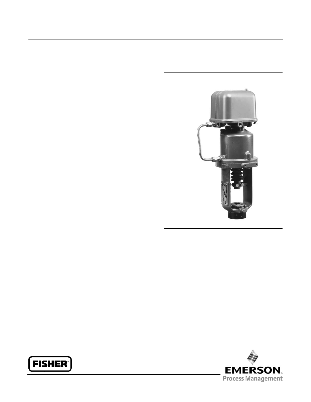
Figure 1. Fisher 3570 Positioner Mounted on
470 Actuator
W5566*/IL
Bias Spring 29................................
Disassembly 29...........................
Assembly 29..............................
Parts Ordering 29...............................
Parts Kits 30...................................
Positioner Repair Kits 30........................
Diagnostic Test Connection Kits 30...............
Parts List 30...................................
Positioner Common Parts 30....................
Introduction
Scope of Manual
This manual provides installation, operation, adjustment, maintenance, and parts ordering information for Fisher
3570 pneumatic valve positioners. The various product types within this series are described later in this manual. Refer
www.Fisher.com
Page 2

3570 Positioners
September 2011
to figure 1 for a typical mounting of a 3570 positioner. Refer to separate instruction manuals for information
concerning the actuator, valve, and accessories.
Do not install, operate or maintain a 3570 positioner without being fully trained and qualified in valve, actuator, and
accessory installation, operation, and maintenance. To avoid personal injury or property damage, it is important to
carefully read, understand and follow all the contents of this manual, including all safety cautions and warnings. If you
have any questions about these instructions, contact your Emerson Process Management sales office before
proceeding.
Instruction Manual
D200137X012
Description
3570 pneumatic valve positioners are used with control valve assemblies to provide an accurate valve stem position
that is proportional to the input signal received from a control device. The input signal range can be 0.2 to 1.0 bar (3 to
15 psig), 0.4 to 2.0 bar (6 to 30 psig), or another pneumatic input signal range, as required.
These positioners are normally used with pneumatic piston actuators. However, product types within the 3570 family
can be used with pneumatic, long‐stroke, cylinder actuators or with pneumatic diaphragm actuators.
Valve Positioner Type Numbers
3570 — Pneumatic valve positioner with two relays for use with Fisher 470 and 480 pneumatic piston actuators. See
figure 4. The positioner includes three pressure gauges to monitor input signal, relay output pressure to the top of the
actuator cylinder, and relay output pressure to the bottom (piston underside) of the actuator cylinder.
The 3570 positioner is mounted on the top of the actuator cylinder. The actuator stem position feedback is provided
through extension of the range spring attached to the actuator piston rod.
3570C — Pneumatic valve positioner with automotive tire valves instead of pressure gauges. Tire valves can be used
for clip‐on test pressure gauges. The relay nozzles are locked in place with locknuts to resist unwanted nozzle
movement due to vibration.
3570P — Pneumatic valve positioner with two relays for use with Fisher 490 pneumatic piston actuators. The
positioner includes three pressure gauges to monitor input signal, relay output pressure to the top of the actuator
cylinder, and relay output pressure to the bottom (piston underside) of the actuator cylinder.
The 3570P positioner is mounted alongside the actuator cylinder. Actuator stem position feedback is provided from
the actuator‐valve stem connector through a cable and spool assembly.
3570PC — Pneumatic valve positioner with automotive tire valves instead of pressure gauges. Tire valves can be used
for clip‐on test pressure gauges. The relay nozzles are locked in place with locknuts to resist unwanted nozzle
movement due to vibration.
3571 (Discontinued)— Pneumatic valve positioner with two relays for use with long‐stroke cylinder actuators. The
positioner includes three pressure gauges to monitor input signal, relay output pressure to the top of the actuator
cylinder, and relay output pressure to the bottom (piston underside) of the actuator cylinder.
The 3571 positioner is bracket‐mounted to the side of the actuator. Actuator stem position feedback is provided
through a wire from the actuator‐valve stem connector.
3572 — Pneumatic valve positioner with one relay. The 3572 positioner is normally used on the 472 pneumatic piston
actuator mounted on valve bodies having push‐down‐to‐open (PDTO) action. The positioner includes two pressure
gauges to monitor input signal pressure and relay output pressure to the top of the actuator cylinder.
The 3572 positioner is mounted on the top of the actuator cylinder. Actuator stem position feedback is provided
through an extension of the actuator piston rod.
2
Page 3
Instruction Manual
D200137X012
Table 1. Specifications
3570 Positioners
September 2011
Available Configurations
See the positioner type number descriptions given
above.
Input Signal
Standard Ranges: 0.2 to 1.0 bar (3 to 15 psig) or 0.4
Supply Pressure
Maximum: 10.4 bar (150 psig)
Minimum: 2.4 bar (35 psig)
Supply Medium
Air or Natural gas
(2)
to 2.0 bar (6 to 30 psig)
Optional Ranges: As desired, within the limits of the
bellows
Split Ranges: Use one‐half of either standard range
when two control valves are operated by one
output signal form a single control device
Steady‐State Air Consumption
0.54 normal m3/h (20 scfh) with 6.9 bar (100 psig)
supply pressure
Operative Ambient Temperature Limits
Output Signal
Type: Pneumatic pressure as required to maintain
the correct valve stem position and seat load
Action: Field‐reversible between direct and reverse
Resolution
(1)
0.2% of instrument pressure span
With Nitrile O‐Rings and Diaphragms: –34 to 71°C
(–30 to 160°F)
With Fluorocarbon O‐Rings and Diaphragms
(Optional): 0 to 104°C (32 to 220°F)
Hazardous Area Classification
Complies with the requirements of ATEX Group II
Category 2 Gas and Dust
Repeatability
(1)
0.3% of total stroke or instrument pressure span
Options
Frequency Response
(1)
J Restrictor (high‐frequency filter for bellows)
See figure 5
Approximate Weight
Pressure Connections
Vent: 3/8 NPT
All others: 1/4 NPT
Pressure Indications
3570C and 3570CP Positioners: Tire valves accept
standard pressure gauge chucks (gauges not
supplied)
All Other Types: Gauges supplied per table 3
2.7 kg (6 pounds) without optional mounting
bracket or actuator/valve assembly
Declaration of SEP
Fisher Controls International LLC declares this
product to be in compliance with Article 3
paragraph 3 of the Pressure Equipment Directive
(PED) 97 / 23 / EC. It was designed and
manufactured in accordance with Sound
Engineering Practice (SEP) and cannot bear the CE
marking related to PED compliance.
Bellows Pressure Rating
Standard Bellows: 3.4 bar (50 psig)
Optional Bellows: 6.2 bar (90 psig)
NOTE: Specialized instrument terms are defined in ANSI/ISA Standard 51.1 - Process Instrument Terminology.
1. For a 3570 or 3570C positioner mounted on a 470 or 480 actuator. Values do not apply to other constructions or actuator‐valve combinations.
2. Natural gas should not contain more than 20 ppm of H
3
3. m
/h at 0°C, 1.01325 bar, absolute (Scfh at 60°F, 14.7 psia).
S.
2
However, the product may bear the CE marking to
indicate compliance with other applicable European
Community Directives.
(3)
(1)
3
Page 4
3570 Positioners
September 2011
Instruction Manual
D200137X012
Table 2. Action Under Normal Operating Conditions
POSITIONER ACTION
Direct‐acting Increasing input signal pressure to bellows Decreasing input signal pressure to bellows
Reverse‐acting Decreasing input signal pressure to bellows Increasing input signal pressure to bellows
1. Supply pressure is routed through relays to piston.
Down Up
DESIRED PISTON MOTION
(1)
Table 3. Pressure Indications
NUMBER OF GAUGES SUPPLIED
PRESSURE MONITORED
Positioner input signal pressure 1 1
Cylinder (relay output) pressure 2 1 0‐160 psi/0‐1.1 MPa/0‐11 bar
1. For gauges marked in other units and ranges, consult your Emerson Process Management sales office.
Two‐Relay
Positioner
One‐Relay
Positioner
0‐30 psi/0‐0.2 MPa/0‐2 bar or
0‐60 psi/0‐0.4 MPa/0‐4 bar
STANDARD GAUGE RANGE
(1)
3573 — Pneumatic valve positioner that is similar to The 3572 positioner with the relay output pressure piped to the
bottom (piston underside) of the actuator cylinder. The 3573 positioner is normally used on the 473 pneumatic piston
actuator with valve bodies having push‐down‐to‐close (PDTC) action.
3576 (Discontinued)— Pneumatic valve positioner with one relay for use on direct‐acting pneumatic diaphragm
actuators that require high operating pressures. The 3576 positioner includes two pressure gauges to monitor input
signal pressure and relay output pressure to the top of the actuator diaphragm.
The 3576 positioner is bracket‐mounted to the actuator yoke. Actuator stem position feedback is provided through a
wire from the actuator‐valve stem connector.
3577 (Discontinued)— Pneumatic valve positioner that is similar to 3576 positioner with the relay output pressure
piped to the underside of the actuator diaphragm on reverse‐acting pneumatic diaphragm actuators.
Specifications
Specifications for 3570 positioners are listed in table 1.
Educational Services
For information on available courses for 3570 positioners, as well as a variety of other products, contact:
Emerson Process Management
Educational Services, Registration
P.O. Box 190; 301 S. 1st Ave.
Marshalltown, IA 50158-2823
Phone: 800-338-8158 or
Phone: 641-754-3771
FAX: 641-754-3431
e‐mail: education@emerson.com
4
Page 5

Instruction Manual
D200137X012
3570 Positioners
September 2011
Installation, Mounting, and Connections
Installation
WARNING
D Always wear protective clothing, gloves, and eyewear when performing any installation operations to avoid personal
injury.
D Personal injury or property damage may result from fire or explosion if natural gas is used as the supply medium and
preventive measures are not taken. Preventive measures may include, but are not limited to, one or more of the
following: Remote venting of the unit, re‐evaluating the hazardous area classification, ensuring adequate ventilation,
and the removal of any ignition sources. For information on remote venting of this positioner, refer to page 8.
D Check with your process or safety engineer for any additional measures that must be taken to protect against process
media.
D If installing this into an existing application, also refer to the WARNING at the beginning of the Maintenance section of
this instruction manual.
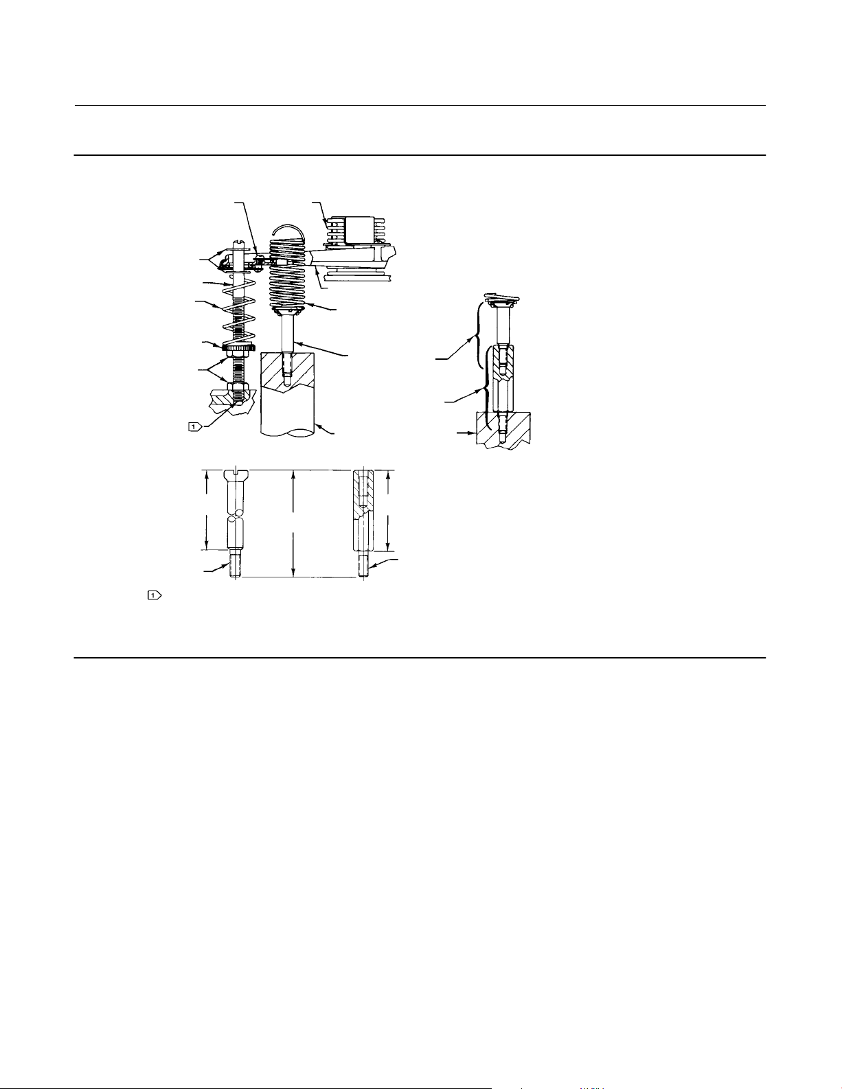
The positioner is usually mounted on the actuator at the factory. However, if the positioner and actuator are ordered
separately, it is necessary to mount the positioner on the actuator. Before mounting the positioner, be certain the
O‐ring (key 33, figure 11) is in place in the cylinder (top connection) in the base of the positioner.
For appropriate actuator/positioner combinations, refer to the positioner type number descriptions given earlier in
this instruction manual.
D For 3570, 3570C, 3572, and 3573 positioners, mount the positioner with two cap screws (key 32, figure 11). If the
range and bias springs are not installed in the positioner, refer to the range spring and bias spring procedures in the
Maintenance section.
Insert the threaded end of the spring retainer (key 19, figure 2) into the center of the range spring (see figure 2). Then,
insert a screwdriver into the center of the range spring and extend the spring until the spring retainer can be screwed
into the top of the actuator piston rod extension. Tighten the spring retainer into the top of the actuator piston rod
extension. If the range spring and/or bias spring is not installed in the positioner, refer to the procedures for either
spring in the Maintenance section.
D For 3570P and 3570PC positioners, attach the positioner extension and positioner to the cylinder mounting plate
with the two cap screws (key 100, figure 14). Make the required pressure connections as described in the following
procedure. Go to the initial range spring extension procedures for 3570P and 3570PC positioners.
D For 3571, 3576, and 3577 positioners, insert two cap screws through the holes in the mounting bracket (key 55,
figure 13) to attach the positioner to the actuator mounting boss. Attach the hex drive stud to the actuator‐valve
stem connection. Attach the end bearing (key 56E, figure 13) to the hex drive stud.
5
Page 6
3570 Positioners
September 2011
Figure 2. Bias and Range Springs for Zero and Span Adjustments
Instruction Manual
D200137X012
BEAM TRAVEL
STOP (E‐RING)
BIAS SPRING POST
BIAS SPRING
ZERO ADJUSTMENT
LOCKNUTS
EFFECTIVE LENGTH
SPRING
RETAINER
NOTE:
BOTTOM OF BIAS SPRING POST THREAD MUST BE POSITIONED
AS SHOWN FOR PROPER POSITION OF E‐RING TRAVEL STOPS.
AJ7270‐C
1H8907‐C
1J2233‐C
B2402/IL
SPRING LOCK
BELLOWS
BEAM
RANGE SPRING
(KEY 18)
SPRING RETAINER
(KEY 19)
SPRING RETAINER SPACER
(IF REQUIRED) (KEY 235)
PISTON ROD EXTENSION
(OPTIONAL)
EFFECTIVE LENGTH
OVERALL
LENGTH
SPRING RETAINER SPACER
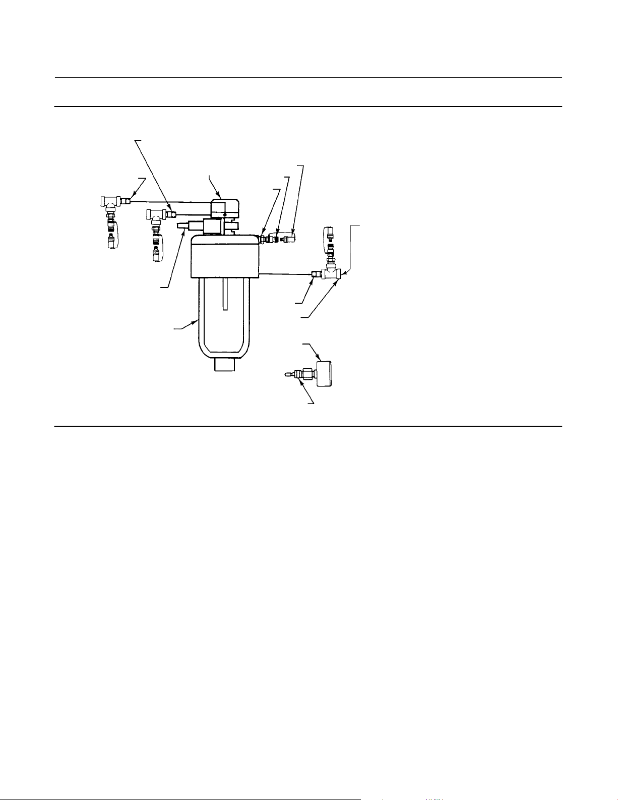
Diagnostic Test Connectors (Optional)
Diagnostic test connectors are available from the factory, when the unit is ordered, or they can be installed on an
existing control valve assembly in the field. These connectors are especially useful for “quick” connections when using
the FlowScannert valve diagnostic system. The FlowScanner is a portable, microprocessor‐based diagnostic and
calibration system specifically designed for use with pneumatically‐operated control valves.
To support diagnostic testing of the control valve assembly, the connectors, piping, and other hardware can be
installed between the 3570 positioner and the actuator. A typical connector installation is shown in figure 3. For
connectors, refer to the FlowScanner Diagnostic Connection kit listing in the parts list.
The hardware used includes 3/4 NPT pipe nipple, pipe tee, and pipe bushings with a 1/8 NPT pipe bushing for the
connector. The connector consists of 1/8 NPT body and body protector (see figure 3).
1. Before assembling the pipe nipple, pipe tee, pipe bushings, actuator piping, and connector body, apply sealant to
all threads.
2. Position the pipe tee, connector body, and body protector for easy access when doing diagnostic testing.
6
Page 7
Instruction Manual
D200137X012
Figure 3. Diagnostic Test Connections
PIPE NIPPLE TO
INSTRUMENT CONNECTION
PIPE NIPPLE
TO SUPPLY
CONNECTION
3570
POSITIONER
3570 Positioners
September 2011
BODY PROTECTOR
BODY
PIPE BUSHING
FROM 377
TRIP VALVE
PIPE NIPPLE
TO BOTTOM
CYLINDER
PIPE TEE
GAUGE
STEM
REQUIRED WHEN
PURCHASED WITH GAUGE
12B8044‐A
A6112/IL
377 TRIP VALVE
(OPTIONAL)
ACTUATOR
Connections
Piping Sizes
All pressure connections on 3570 positioners are 1/4 NPT (internal). Use 3/8‐inch pipe or tubing for supply, cylinder
(bottom connection), and instrument (input signal) connections. For the remote vent pipe, if one is required, use 19
mm (3/4‐inch) (minimum inside diameter) pipe for runs up to 6.09 meters (20 feet). For vent piping runs from 6.09 to
30.5 meters (20 to 100 feet), use 25.4 mm (1‐inch) (minimum inside diameter) pipe. Refer to figure 4 for the locations
and sizes of connections.
7
Page 8
3570 Positioners
September 2011
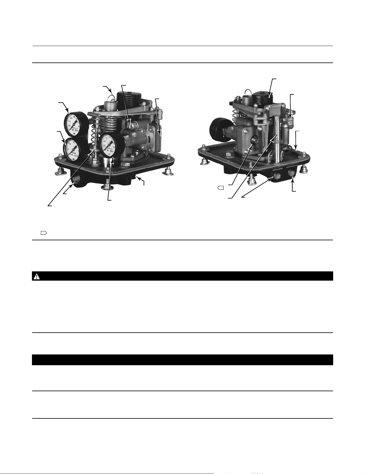
Figure 4. Typical Location of Fisher 3570 Positioner Parts and Adjustments
Instruction Manual
D200137X012
RANGE SPRING
(SPAN ADJUSTMENT)
CYLINDER
BOTTOM
PRESSURE
INSTRUMENT
PRESSURE
VENT CONNECTION
3/8 NPT
ZERO ADJUSTMENT
W4025*/IL
NOTES:
1
ON SOME CONSTRUCTIONS, TWO NOZZLES AND ADJUSTMENTS ARE REQUIRED.
FRONT VIEW
CLEAN‐OUT
PLUNGER
CYLINDER
TOP PRESSURE
CYLINDER
(TOP CONNECTION)
(O‐RING, KEY 33)
HORIZONTAL
RELAY
RELAY NOZZLE
(OUTPUT PRESSURE
ADJUSTMENT)
BELLOWS POSTS
1
W4027*/IL
BELLOWS
CYLINDER (BOTTOM
CONNECTION) (1/4 NPT)
BACK VIEW
VERTICAL
RELAY
SUPPLY
CONNECTION
(NOT SHOWN)
(1/4 NPT)
INSTRUMENT
CONNECTION
(INPUT SIGNAL)
(1/4 NPT)
Vent
WARNING
Personal injury or property damage could result from fire or explosion of accumulated gas, or from contact with hazardous
gas, if a flammable or hazardous gas is used as the supply pressure medium.
The positioner/actuator assembly does not form a gas‐tight seal, and flammable or hazardous gas could leak from the
assembly. Therefore, if the assembly is enclosed install a remote vent line from the enclosure. However, a remote vent pipe
alone cannot be relied upon to remove all hazardous gas. Use adequate ventilation, and necessary safety measures. Vent
line piping should comply with local and regional codes and should be as short as possible with adequate inside diameter
and few bends to reduce case pressure buildup.
CAUTION
When installing a remote vent pipe, take care not to overtighten the pipe in the vent connection. Excessive torque will
damage the threads in the connection.
Note
The vent connection is always plugged with a pipe plug for 3570P and 3570PC positioners when mounted on 490 actuators.
8
Page 9

Instruction Manual
D200137X012
3570 Positioners
September 2011
The connection marked VENT (see figure 4) should be left open if the actuator is installed in the vertical position.
However, the vent must be protected against the entrance of any foreign material that could plug it. Check the vent
periodically to be certain it is not plugged.
If the actuator is mounted in other than the vertical position, be sure there is a vent and drain at the lowest point of the
positioner. To do this, remove the pipe plug (key 36, figure 11) from the cover. Then, position the cover in such a way
that the hole in the cover is at the lowest point. Plug the vent connection because the positioner is now vented
through the cover.
Note
A remote vent is not possible with 3570P, 3570PC, 3571, 3576, and 3577 positioners.
If a remote vent is required, the vent line must be as short as possible with a minimum number of bends or elbows.
Vent line piping should have a minimum inside diameter of 19 mm (3/4‐inch) for runs up to 6.09 meters (20 feet) and
a minimum inside diameter of 25.4 mm (1‐inch) for runs from 6.09 to 30.5 meters (20 to 100 feet).
Supply Pressure Connections
WARNING
Personal injury or property damage may occur from an uncontrolled process if the supply medium is not clean, dry, oil‐free
air, or noncorrosive gas. While use and regular maintenance of a filter that removes particles larger than 40 micrometers in
diameter will suffice in most applications, check with an Emerson field office and industry instrument air quality standards
for use with corrosive air or if you are unsure about the proper amount or method of air filtration or filter maintenance.
WARNING
To avoid personal injury or property damage resulting from the sudden release of pressure, do not install the valve
assembly where service conditions could exceed the limits given in this manual or on the appropriate nameplates. Use
pressure‐relieving devices as required by government or accepted industry codes and good engineering practices.
WARNING
If the supply pressure medium is corrosive, make sure the tubing and instrument components that contact the corrosive
medium are of suitable corrosion‐resistant material. The use of unsuitable materials might result in personal injury or
property damage due to the uncontrolled release of the corrosive media.
The connection marked SUPPLY (see figure 4) must be provided with clean, dry air or a noncorrosive gas. Install a
40‐micrometer filter and suitable equipment to dry the supply medium. Establish a maintenance cycle to ensure that
the regulator and filter are working correctly.
CAUTION
The maximum allowable supply pressure to prevent damage to the components of the positioner, actuator, and valve is
normally stamped on the actuator nameplate. Use a suitable supply pressure regulator to reduce the supply pressure
source to the value stamped on the nameplate.
9
Page 10

3570 Positioners
September 2011
If this maximum supply pressure value is not available, use a supply pressure that does not exceed any of the following:
D The maximum supply pressure for the positioner as shown in table 1.
D The maximum pressure rating of the actuator, from the appropriate actuator instruction manual.
D The maximum allowable valve plug stem load for the specific valve body assembly being used. Contact your
Emerson Process Management sales office for valve plug stem load information, if required.
D For diaphragm actuators, refer to the actuator instruction manual for the recommended supply pressure and use
the larger value of the range listed.
The recommended supply pressure for use with piston actuators is the highest available supply pressure between 3.4
bar (50 psig) and the maximum limit determined by the actuator and positioner specifications. Selecting the highest
pressure within the limits will minimize load error and will maximize stroking speed and thrust. For the lowest supply
pressure that will assure satisfactory performance, the factors of valve plug unbalance force, valve plug seating force,
and frictional force must be considered in the following relationship:
Instruction Manual
D200137X012
(Valve
unbalance,
Supply
pressure, = 98
bar
or
Supply
pressure, =
psig
Consult your Emerson Process Management sales office for the appropriate values for specific actuators, valves, and
service conditions. The 0.7 bar (10 psig) is added to the equation to account for an approximate 0.7 bar (10 psi)
differential pressure loss in the positioner. For spring‐return piston actuators, the pressure required to compress the
actuator spring completely must also be considered.
[
kg)
(Valve
unbalance,
[
pounds)
(Area of the actuator piston,
(Area of the actuator piston,
(Seating
+
force,
kg)
in square mm)
(Seating
+
force,
pounds)
in square inches)
(Frictional
+
force,
kg)
(Frictional
+
force,
pounds)
]
]
+ 0.7 bar
+ 10 psig
Cylinder Connections
1. The connection marked CYLINDER (see figure 4) is connected at the factory to the lower part of the cylinder
(bottom) or to the lower diaphragm casing if the positioner is used with a pneumatic diaphragm actuator.
2. The cylinder top connection is a pressure passage located in the bottom of the positioner base (key 1, figure 11). On
3570 and 3570C positioners, an O‐ring (key 33, figure 11) is used between the bottom of the positioner and the top
of the actuator. On 3570P, 3570PC, 3571, 3576, and 3577 positioners, a mounting bracket (key 55, figure 13) is
required. This mounting bracket connects to the bottom of the base. An O‐ring (key 33, figure 11) is placed
between the base and mounting bracket. This mounting bracket provides a 1/4 NPT connection for the positioner
output. This connection is made at the factory if the positioner is ordered mounted to the actuator or if the
mounting bracket is installed.
Instrument Connection
The connection marked INSTRUMENT (see figure 4) connects to the output signal connection of the control device.
The positioner operates only on a pneumatic input signal; the input signal range is marked on the nameplate (key 23,
10
Page 11

Instruction Manual
D200137X012
figure 11). The maximum allowable input signal for positioners with standard or optional bellows is in table 1 (bellows
pressure rating). The instrument connection is made at the factory when a complete control valve assembly with a
valve‐mounted control device is ordered. Otherwise, make field connections to the positioner from an appropriate
control device. Refer to table 1 and the nameplate for input signal pressure ranges.
3570 Positioners
September 2011
Operating Information
Initial Adjustments
Normally, no adjustments are necessary upon initial installation. The positioner is set at the factory for the travel, input
signal range, and action specified in the order. Adjustment is necessary when operating conditions are changed, when
the unit has been dismantled and reassembled, or when the control valve travel does not correspond to the desired
input signal range. If the operating conditions have not changed but the positioner requires adjustment, refer to the
adjustment procedures in this section. If the operating conditions have changed, first, refer to the signal range code
descriptions, then, refer to the adjustment procedures.
Signal Range Codes
The range spring and the bias spring are matched to a specific input signal range and length of travel. Also, the spring
retainer length is matched to the application on the 3570, 3570C, 3572, and 3573 positioners. Refer to figure 2 for
location of parts.
The signal range codes in table 4 are based on the following applications:
D Codes for valve travels up to and including 50 mm (2 inches) are used for actuators that have a 50 mm (2 inch)
maximum travel. If the actuator maximum travel is greater than 50 mm (2 inches), an additional retainer spacer
(key 235, see figure 2) is required. Refer to the parts list for the additional spring retainer spacer (key 235) part
number.
D Codes for valve travels greater than 50 mm (2 inches), up to and including 105 mm (4‐1/8 inches), are used for
actuators that have a 105 mm (4‐1/8 inch) maximum travel, except the 480‐12 or 480‐15 Size 20 actuators which
have a 54 mm (2‐1/8 inch) maximum travel. If the actuator maximum travel is greater than 105 mm (4‐1/8 inches),
an additional retainer spacer are required. Refer to the parts list for the additional spring retainer spacer (key 235)
part numbers.
D Codes for valve travels greater than 105 mm (4‐1/8 inches), up to and including 206 mm (8‐1/8 inches), are for
actuators that have a 206 mm (8‐1/8 inch) maximum travel. If the valve travel is 105 mm (4‐1/8 inches) or less, two
additional spring retainer spacers are required. Refer to the parts list for the additional spring retainer spacer (key
235) part numbers.
If the input signal range and travel do not match any of the selections in table 4, consult your Emerson Process
Management sales office for information. To change the springs, refer to the range and bias spring procedures in the
Maintenance section.
From table 4, select the signal range that matches your application. Find the travel length for the application under the
signal range selected, then use the code (from the direct or reverse column) that matches the direct or reverse
operation of the positioner.
The first number in the code is used to identify the range spring, the letter in the code is used to identify the bias
spring, and the second number (after the letter) is used to identify the spring retainer. For example, from table 4, for a
11
Page 12

3570 Positioners
September 2011
Instruction Manual
D200137X012
signal range of 0 to 1.0 bar (0 to 15 psig), an actuator travel of 14.3 mm (9/16‐inch), and direct action, the signal
range code from table 4 is 6G3. The “6” indicates the range spring. The “G” indicates the bias spring. The “3” indicates
the spring retainer.
Note
It is necessary to add the bias spring seat (key 8) to a unit when changing from an extension type spring (key 9) to a compression
type spring (key 48).
When planning to change the bias spring in an existing unit, inspect the unit first to determine if the current bias
spring is an extension type spring (key 9) or a compression type spring (key 48). To change from an extension type
spring to a compression type spring, it is necessary to add the bias spring seat (key 8). Refer to the appropriate
procedures in the Maintenance section of this manual.
In some cases, it is necessary to add an additional spring retainer spacer or change from the standard bellows to the
optional high pressure bellows. Table 4 footnotes indicate the use of an additional spring retainer spacer or high
pressure bellows.
Use the code from table 4 while referring to tables 5, 6, and 7 to determine the part numbers for the range spring, bias
spring, and spring retainer. Unless otherwise specified, use the standard bellows. Also, no spring retainer spacer is
required unless the spacer is specified in the footnotes of table 4.
Frequency Response
Figure 5 shows how a 3570 or 3570C positioner with 470 or 480 actuator responds when the input signal pressure is
cycled at a small amplitude (3 to 5 percent), and at an increasing frequency. Assume the cycling input signal and the
movement of the actuator rod are represented by sine waves. As the actuator rod is forced to move faster, its motion
begins to fall behind the input signal in both time (shown as phase lag) and amplitude (shown as normalized gain).
Figure 5. Typical Frequency Response for a Fisher 3570 or 3570C Positioner Mounted on a 470 or 480 Actuator
1. SIZE 30—19 mm (3/4 INCH) TRAVEL4. SIZE 80—51 mm (2 INCH) TRAVEL
2. SIZE 40—38 mm (1‐1/2 INCH) TRAVEL 5. SIZE 100—51 mm (2 INCH) TRAVEL
3. SIZE 60—38 mm (1‐1/2 INCH) TRAVEL 6. SIZE 130—76 mm (3 INCH) TRAVEL
2K5255‐R
A1285‐2/IL
12
Page 13

Instruction Manual
D200137X012
3570 Positioners
September 2011
Table 4. Fisher 3570 Signal Range Codes
SIGNAL RANGE
0 to 1.0 bar (0 to 15 psig)
0.2 to 0.6 bar (3 to 9 psig)
(1)
SIGNAL RANGE
SIGNAL RANGE
0.2 to 1.0 bar (3 to 15 psig)
SIGNAL RANGE
0.2 to 1.0 bar (3 to 15 psig)
Travel Code Travel Code Travel Code Travel Code
mm Inches Direct Reverse mm Inches Direct Reverse mm Inches Direct Reverse mm Inches Direct Reverse
14.3
17.5
19
20.6
26.2
9/16
11/16
3/4
13/16
1‐1/32
6G3
2G4
7A1
7G1
5A12
6D3
2G4
7C1
7B1
5D12
66.7
76.2
79.4
82.6
85.7
2‐5/8
3
3‐1/8
3‐1/4
3‐3/8
15G13
14G8
14G8
14G8
14G8
15A13
14A8
14A8
14A8
14A8
54542‐1/8
55.6
57.1
58.7
59.5
28.6
30.2
38.1
39.7
44.5
1‐1/8
1‐3/16
1‐1/2
1‐9/16
1‐3/4
5C8
12A13
8G5
8G12
8G5
5C8
12C13
8B5
8B12
8A5
88.9
96.8
101.6
104.8
117.5
3‐1/2
3‐13/16
4
4‐1/8
4‐5/8
14G8
14G8
14G8
13G8
(2)
13G3
14A8
14A8
14A8
13A8
13A3
60.3
63.5
66.7
68.3
69.9
50.8
79.4
101.6
104.8
127
2
3‐1/8
4
4‐1/8
5
8G5
9A3
9A12
9G1
21B8
SIGNAL RANGE
0 to 2.0 bar (0 to 30 psig)
15.9
25.4
28.6
33.3
38.1
50.8
76.2
79.4
101.6
104.844‐1/8
5/8
3/4
10D2
10D3
1
11A4
11A5
11A12
11D12
2
2G5
(2)
12G7
(8)
12G10
12C3
3
(2)
12A8
19
1‐1/8
1‐5/16
1‐1/2
54
2‐1/8
54
2‐1/8
3‐1/8
1G1
1G1
SIGNAL RANGE
0.2 to 0.6 bar (3 to 9 psig)
11.1
12.7
15.9
19
22.2
25.4
27
28.6
35
38.1
41.3
50.8
54
54
58.7
63.5
7/16
1‐1/16
1‐1/8
1‐3/8
1‐1/2
1‐5/8
2‐1/8
2‐1/8
2‐5/16
2‐1/2
1/2
5/8
3/4
7/8
5G5
8G5
8G10
8G13
8G8
1
4G8
4G8
9G8
9G8
9G8
9G8
2
15G8
15A1
(8)
15G5
15G1
15G3
8A5
9B3
9B12
9B1
21D8
10D2
10D3
11D4
11D5
11D12
11D12
2D5
12D7
12D10
12C3
12D8
1D1
1C1
5A5
8A5
8A10
8A13
8B8
4B8
4B8
9A8
9A8
9A8
9A8
15A8
15A1
15A5
15A1
15A3
127
152.4
165.1
177.8
203.2
206.4
(3)
5
6
6‐1/2
7
8
8‐1/8
13G4
13G3
13G3
13G8
18G8
18G8
SIGNAL RANGE
0.2 to 1.0 bar (3 to 15 psig)
3.2
1/8
17H4
3.2
4
6.4
8.7
9.5
11.1
11.9
12.7
14.8
15.9
17.5
19
20.6
22.2
23.8
25.4
27
28.6
31.8
33.3
35
36.5
38.1
39.7
41.3
44.5
46
47.6
50.8
(6)
1/8
5/32
1/4
11/32
3/8
7/16
0.469
1/2
0.582
5/8
11/16
3/4
13/16
7/8
15/16
1
1‐1/16
1‐1/8
1‐1/4
1‐5/16
1‐3/8
1‐7/16
1‐1/2
1‐9/16
1‐5/8
1‐3/4
1‐13/16
1‐7/8
2
10D3
10D2
10B4
6A3
6A3
6A4
6A4
7G1
5G4
7G3
7G4
7G4
7A5
5G5
8G5
8G5
8G12
8G12
8G12
8G10
8G10
8G13
8G13
8G8
8G8
8G8
4G8
4G7
4G8
13A4
13A3
13A3
13A8
18A8
18A8
17H4
10D3
10H2
10H4
6C3
6C3
6D4
6D4
7C1
5C4
7B3
7B4
7C4
7B5
5C5
8B5
8B5
8B12
8B12
8B12
8C10
8B10
8B13
8B13
8C8
8B8
8B8
4C8
4B7
4B8
73
74.6
76.2
78.5
79.4
82.6
84.9
85.7
86.5
88.9
92
92.9
95.3
96.8
100
101.6
101.6
104.8
108
111.1
114.3
116.8
117.5
120.7
127
133.4
139.7
152.4
155.6
165.1
169.9
171.5
173
177.8
181.8
188.1
-Continued-
2‐1/8
2‐3/16
2‐1/4
2‐5/16
2‐11/32
2‐3/8
2‐1/2
2‐5/8
2‐11/16
2‐3/4
2‐7/8
2‐15/16
3.09
3‐1/8
3‐1/4
3‐11/32
3‐3/8
3‐13/32
3‐1/2
3‐5/8
3‐21/32
3‐3/4
3‐13/16
3‐15/16
4
4‐1/8
4‐1/4
4‐3/8
4‐1/2
4.6
4‐5/8
4‐3/4
5
5‐1/4
5‐1/2
6
6‐1/8
6‐1/2
6‐11/16
6‐3/4
6‐13/16
7‐5/32
7‐13/32
(3)
4G1
(8)
4G8
9G3
9G3
(3)
9G2
9G3
9G3
4B1
4B8
9B3
9B3
9B2
9B3
9B3
190.5
193
196.6
198.9
203.2
206.4
7‐1/2
7.6
7‐3/4
7‐13/16
8
8‐1/8
19G5
19G8
19G3
19G8
19G8
19G12
19C5
19C8
19B3
19B8
19B8
19B13
SIGNAL RANGE
0.2 to 1.8 bar (3 to 27 psig)
9G3
9B3
9G10
9G10
9G5
9G5
3
9G12
9G8
9G7
9G10
9G8
9G13
9G10
9G13
9G13
9G8
9G8
9G8
21G8
4
21G8
(6)
14G1
16G8
(4)
16G13
(2)
16G1
(6)
20A8
(4)
16G4
(2)
16G3
(2)
16G3
(5)
14G1
(5)
16G10
(5)
14G1
(5)
13G3
(5)
13G3
(5)
13G3
20G3
(5)
13G5
20G3
20G5
7
(2,6)
13G1
20G3
9B3
9B3
9B10
9B10
9B5
9B5
9A12
9B8
9B7
9B10
9B8
9B13
9B10
9B13
9B13
9B8
9B8
9C8
21B8
21A8
14A1
16B8
16D13
16C1
20C8
16C4
16B3
16B3
14C1
16C10
14B1
13A3
13A3
13A3
20B3
13A5
20A3
20C5
13A1
20B3
9.5
11.1
15.9
22.2
25.4
28.6
31.8
33.3
38.1
43.9
47.6
50.8
63.5
76.2
79.4
82.6
88.9
101.6
104.8
114.3
127
133.4
152.4
190.5
203.2
3/8
10A2
7/16
10A2
5/8
3/4
7/8
3A2
11A4
11A5
1
2C5
2A5
5G4
2A12
2C10
2G12
2G10
2
5G10
12A3
(8)
12G13
1A3
3
1B12
1A12
4G1
4G4
4
4G1
4G5
(7)
21A13
(6)
21A4
(6)
21A3
(5)
16G3
(2)
21G1
(4)
21G10
19
1‐1/8
1‐1/4
1‐5/16
1‐1/2
1.73
1‐7/8
54
2‐1/8
54
2‐1/8
2‐1/2
3‐1/8
3‐1/4
3‐1/2
4‐1/8
4‐1/2
5
5‐1/4
6
7‐1/2
8
SIGNAL RANGE
0.4 to 1.2 bar (6 to 18 psig)
19
3/4
28.6
38.1
50.8
54
54
76.2
101.6
104.8
152.4
1‐1/8
1‐1/2
2‐1/8
2‐1/8
4‐1/8
6
5G5
8G12
8G8
2
4G8
9G3
(8)
9G12
3
9G5
4
21G8
16G8
(4)
13G1
10D2
10D2
3D2
11D4
11D5
2C5
2D5
5D4
2D12
2C10
2D12
2C10
5D10
12D3
12D13
1D3
1D12
1D12
4C1
4D4
4B1
4D5
21D13
21D4
21D3
16C3
21D1
21D10
5C5
8B12
8B8
4B8
9C3
9B12
9C5
21B8
16B8
13B1
13
Page 14

3570 Positioners
September 2011
Instruction Manual
D200137X012
Table 4. Fisher 3570 Signal Range Codes
SIGNAL RANGE
0.4 to 1.2 bar (6 to 18 psig)
0.4 to 2.0 bar (6 to 30 psig)
(1)
(Continued)
SIGNAL RANGE
SIGNAL RANGE
0.6 to 1.0 bar (9 to 15 psig)
SIGNAL RANGE
0.6 to 1.0 bar (9 to 15 psig)
Travel Code Travel Code Travel Code Travel Code
mm Inches Direct Reverse mm Inches Direct Reverse mm Inches Direct Reverse mm Inches Direct Reverse
6‐1/2
8‐1/8
(5)
13G3
19G5
13A3
19C5
165.1
206.4
SIGNAL RANGE
0.4 to 2.0 bar (6 to 30 psig)
6.4
1/4
17H4
9.5
11.1
12.7
15.9
19
22.2
25.4
26.2
28.6
31.8
35
38.1
39.7
41.3
46
48.3
50.8
54
54
1. For 3570P signal range codes, contact your Emerson Process Management sales office.
2. Use spring retainer spacer 1J803846172; for additional information, see table 7.
3. Use spring retainer spacer 1J223346172; for additional information, see table 7.
4. Use spring retainer spacer 1J803946172; for additional information, see table 7.
5. Use with high pressure bellows and spring retainer spacer 1J803946172; for additional information, see table 7.
6. Use with high pressure bellows.
7. Use with high pressure bellows and spring retainer spacer 1J223346172; for additional information, see table 7.
8. For use with 480‐12 or 480‐15 size 20 actuators.
(6)
3/8
7/16
1/2
5/8
3/4
7/8
1
1‐1/32
1‐1/8
1‐1/4
1‐3/8
1‐1/2
1‐9/16
1‐5/8
1‐13/16
1.9
2
2‐1/8
2‐1/8
10A4
10A2
10A2
3G2
11G4
11A5
2G4
2G4
2G5
2G5
2G12
5G5
5G5
5G5
5G5
12G13
12C8
(3)
12G7
(8)
12G13
17H4
10H4
10H2
10D2
3H2
11H4
11H5
2D4
2H4
2D5
2D5
2D12
5D5
5D5
5D5
5D5
12H13
12C8
12D7
12D13
57.1 2‐1/4 12G1 12D1
58.4
60.3
63.5
66.7
69.9
76.2
79.4
82.6
84.1
85.7
88.9
90.5
92.9
95.3
101.6
104.8
133.4
142.9
152.4
165.1
177.8
203.2 8
127
2.3
2‐3/8
2‐1/2
2‐5/8
2‐3/4
3
3‐1/8
3‐1/4
3‐5/16
3‐3/8
3‐1/2
3‐9/16
3‐21/32
3‐3/4
4
4‐1/8
(6)
5
5‐1/4
5‐5/8
(5)
6
6‐1/2
(4)
7
(4)
12G3
12A10
1G3
1G3
1G4
1G1
4G1
4G1
4G3
4G1
1G12
4G1
4G1
4G1
4G4
4G12
21A5
(6)
21A13
(6)
16G1
16G3
(2)
16G1
21G12
21E12 21D12
12C3
12D10
1H3
1D3
1D4
1D1
4C1
4C1
4D3
4H1
1D12
4D1
4D1
4D1
4D4
4D12
21H5
21D13
16D1
16C3
16C1
21D12
8.7
11.1
12.7
15.9
17.5
19
25.4
28.6
38.1
41.3
50.8
54
54
58.7
63.5
73
76.2
79.4
82.6
87.3
88.9
90.5
96.8
101.6
11/32
7/16
1/2
5/8
11/16
3/4
1
1‐1/8
1‐1/2
1‐5/8
2
2‐1/8
2‐1/8
2‐5/16
2‐1/2
2‐7/8
3
3‐1/8
3‐1/4
3‐7/16
3‐1/2
3‐9/16
3‐13/16
4
5A13
5G5
12G13
8G8
8G8
8G10
4F8
9G8
9F8
9F8
5D13
5B5
12B13
8B8
8C8
8B10
4B8
9B8
9B8
9B8
104.8
117.5
152.4
155.6
165.1
177.8
203.2
206.488‐1/8
127
4‐1/8
4‐5/8
(3)
5
6
6‐1/8
6‐1/2
7
14G8
13G3
13G12
13G3
13G4
13G12
13G3
18G8
18G8
14B8
13B8
13B12
13B3
13B4
13B12
13B3
18B8
18B8
SIGNAL RANGE
1.2 to 2.0 bar (18 to 30 psig)
15G8
15G1
(8)
15F5
15G1
15F1
14G8
14G8
14G8
14G8
14G8
14G8
20F8
14G8
14G8
15B8
15B1
15B5
15C1
15A1
14B8
14B8
14B8
14B8
14B8
14B8
20A8
14B8
14A8
19
28.6
38.1
50.8
76.2
79.4
82.6
101.6
104.8
127
133.4
165
206.4
3/4
1‐1/8
1‐1/2
3‐1/8
3‐1/4
4
4‐1/8
5
5‐1/4
6‐1/2
8‐1/8
5G10
5G8
8F5
2
4F8
3
9G8
9F8
9F8
(6)
14E8
16F8
(5)
14F1
(3)
19F3
(5)
13F3
(5)
18F1
5D10
5D8
8C5
4D8
9H8
9C8
9C8
14D8
16D8
14D1
19D3
13B3
18D1
Adjustment Procedures
Refer to figure 2. 3570 positioners have three adjustments:
D The bias spring. It is the zero adjustment which determines the starting point of the valve plug travel.
D The range spring. It is the span adjustment which determines the full valve plug travel for a given input signal range.
D The relay nozzle adjustment. This adjustment determines the steady‐state positioner output pressure.
To illustrate the use of the various adjustments, assume that the positioner has been repaired or has become
completely out of adjustment. Assume also that the input signal range is 0.2 to 1 bar (3 to 15 psig). Proceed as follows:
1. Make sure the input signal range and the valve travel stamped on the nameplate agree with the present operating
conditions.
2. Loosen the four thumb screws on the underside of the positioner base and remove the cover.
3. Provide a means for varying the input signal pressure from zero to 0.07 or 0.14 bar (1 or 2 psig) above the higher
value of the input signal range (see table 1). Provide an accurate means of measuring the input signal pressure.
14
Page 15

Instruction Manual
D200137X012
3570 Positioners
September 2011
Check the accuracy of the positioner instrument pressure gauge (see figure 4). The gauge accuracy is ±0.04 bar
(±0.6 psig) on a 0 to 2 bar (0 to 30 psig) gauge, and ±0.08 bar (±1.2 psig) on a 0 to 2 bar (0 to 60 psig) gauge. This
accuracy is measured at the mid‐point of the full range of the scale.
4. Set the input signal pressure at the mid‐point of its range [0.6 bar (9 psig) in this example]. Observe the valve travel
indicator scale attached to the yoke. The indicator disk should be somewhere between the open and closed
positions.
5. Loosen the locknut directly below the bias spring seat (see figure 2) and adjust the bias spring up or down until the
valve travel indicator disk shows that the valve plug is somewhere between the open and closed positions. Upward
movement of the bias spring adjustment causes downward travel of the valve stem.
6. For positioners with two relays (3570, 3570C, 3570P, 3570PC, and 3571 positioners), observe the relay output
pressures. If the cylinder gauges are present as shown in figure 4, read the cylinder top and cylinder bottom gauges
or use clip‐on test pressure gauges. The two relay output pressures should be approximately equal [within 0.3 bar (5
psig)] and should be approximately 75 percent of the supply pressure. For example, if the supply pressure is 7 bar
(100 psig), the two relay output pressures should be within 0.3 bar (5 psig) of each other, and should be
approximately 5.2 bar (75 psig).
CAUTION
The relays in the 3570C and 3570PC positioners use a locknut (key 29P, figure 11) on the nozzle (key 29Q). If the nozzle is
rotated when the locknut is tight, damage to the relay diaphragm might result. Always use a wrench on the nozzle to
prevent it from turning while loosening or tightening the locknut.
If the relay output pressures are not at the values mentioned, adjust the nozzles. Counterclockwise rotation of either
nozzle will move the nozzle closer to the beam and will increase relay output pressure.
For all 3570 positioners, examine the end of the beam near the bias spring (see figure 2). The beam should be
approximately centered between the two E‐ring travel stops. Observing the caution above for 3570C and 3570PC
positioners, rotate the nozzle(s) to center the beam between the E‐rings. For positioners with two relays, the relay
output pressures must be approximately equal [within 0.3 bar (5 psig)] and approximately 75 percent of supply
pressure after the beam is centered.
7. Apply an input signal equal to the low value of the input signal range [0.2 bar (3 psig) in this example]. Adjust the
bias spring (see figure 2) up or down until the valve travel is at the starting point.
8. Loosen the spring lock (see figure 2) and slowly increase the input signal toward the high end of the input signal
range [1.0 bar (15 psig) in this example]. If the valve travel is less than its expected range, increase the travel by
adjusting the range spring counterclockwise. If the valve travel reaches the end of its expected range with an input
signal less than the high value of the input signal range, decrease the travel by adjusting the range spring clockwise.
9. Repeat steps 7 and 8 until the valve plug or travel indicator action corresponds to the input signal requirements of
the application [0.2 to 1.0 bar (3 to 15 psig) in this example].
10. Lock the range spring and the bias spring seat in position. The positioner is then ready for operation.
11. If the positioner is unstable and adjustment does not correct the problem, it might be due to unwanted fluctuations
in the input signal. A restrictor assembly (key 47, figure 11) can be installed in the input signal circuit to dampen
these fluctuations. The restrictor might help to minimize instability. To take the restrictor out of service, exchange
the location of the restrictor with that of the bellows mounting screw (key 46, figure 11).
12. Replace the cover (key 39) on the positioner.
15
Page 16

3570 Positioners
September 2011
Instruction Manual
D200137X012
Table 5. Range
1. The range spring code number is the first number given in each signal range code listed in table 4. For example, for a signal range of 0 to 1.0 bar (0 to 15 psig), an actuator travel of 14.3 mm
(9/16‐inch), and direct action, the signal range code from table 4 is 6G3. The appropriate range spring is indicated by “6”.
2. Range springs do not have a color code. All range springs are silver.
3. The first six numbers of a range spring part number is also the tag number. For example, a range spring with part number 1H8914 000A2 has a tag number of 1H8914. Tags are attached to
the parts at the time the parts are manufactured.
(1,2)
Code Number Part Number
1
2
3
4
5
6
7
8
9
10
11
12
13
14
15
16
17
18
19
20
21
22
1H8914000A2
1H8915000A2
1H8916000A2
1H8917000A2
1H8918000A2
1H8919000A2
1H8920000A2
1H8921000A2
1H8922000A2
1H8955000A2
1H895627012
1H8957000A2
1J5185000A2
1J5715000A2
1K5363000A2
1K6684000A2
1R613527012
1R2822000A2
1R853527012
1R899827012
1U582727012
17A3811X022
(3)
Table 6. Bias Spring
(1,2)
Code Letter Color Code Part Number
A
B
C
D
E
F
G
H
1. The bias spring code letter is the letter given in each signal range code listed in table 4. For example, for a signal range of 0 to 1.0 bar (0 to 15 psig), an actuator travel of 14.3 mm (9/16‐inch),
and direct action, the signal range code from table 4 is 6G3. The appropriate bias spring is indicated by “G”.
2. It is necessary to add the bias spring seat (key 8) to a unit when changing from an extension type spring (key 9) to a compression type spring (key 48).
3.Compression type bias spring (key 48).
4. Extension type bias spring (key 9).
Silver
Light blue
Red
Light green
Dark green
Pink
Black
Brown
1H861827012
1H893227012
1H893327012
1H896827012
1J2932X00A2
1J2933000A2
1N7177000A2
1R613427012
(3)
(3)
(3)
(3)
(4)
(4)
(4)
(3)
Table 7. Spring Retainer
CODE NUMBER
(1)
1
2
3
4
5
7
8
10
12
13
1. Code numbers 6, 9, and 11 are not used.
2. Refer to figure 2.
3. The spring retainer code number is the second number given in each signal range code listed in table 4. For example, for a signal range of 0 to 1.0 bar (0 to 15 psig), an actuator travel of 14.3
mm (9/16‐inch), and direct action, the signal range code from table 4 is 6G3. The appropriate spring retainer is indicated by “3”.
OVERALL LENGTH
mm Inches mm Inches
57
53
50
48
43
25
22
35
38
29
(2)
2‐15/64
2‐5/64
1‐63/64
1‐7/8
1‐11/16
31/32
7/8
1‐3/8
1‐1/2
1‐1/8
EFFECTIVE LENGTH
44
40
38
35
30
12
10
22
25
16
(2)
1‐47/64
1‐37/64
1‐31/64
1‐3/8
1‐3/16
15/32
3/8
55/64
1
21/32
PART NUMBER
1H8907X0012
1H8908X0012
1H8909X0012
1H8911X0012
1H8910X0012
1H8912X0012
1H8552X0012
1H8913X0012
1J3572X0012
1J9796X0012
(3)
16
Page 17

Instruction Manual
D200137X012
3570 Positioners
September 2011
Table 8. Spring Retainer Spacer
OVERALL
(1)
LENGTH
mm Inches mm Inches
41
52
57
94
97
1. Refer to figure 2.
2. The spacer number is the first 6 characters of the part number and is stamped on the part.
1‐5/8
2‐1/16
2‐1/4
3‐11/16
3‐13/16
29
40
44
81
84
EFFECTIVE
LENGTH
(1)
1‐1/8
1‐9/16
1‐3/4
3‐3/16
3‐5/16
PART NUMBER
1L2069X0012
1J223346172
1J803846172
1P3957X0012
1J803946172
(2)
Changing Positioner Action
The instructions given below are to be used after the springs have been changed or if no spring change is required.
Numbered parts mentioned in this section are shown in figure 6 unless otherwise noted.
Figure 6. Bellows Mounting for Direct and Reverse Action
2
BEAM
BELLOWS BASE
PEDESTAL
1—MOUNTING SCREW
2—MOUNTING SCREW
3—BELLOWS POST
A1088‐1/IL
WARNING
2
1
BELLOWS TOP VIEW
WITH OPTIONAL RE
STRICTOR
1
DIRECT
ACTION
1
2
2
3
1
RESTRICTOR
2
1
BELLOWS BASE
2
BEAM
3
PEDESTAL
REVERSE
ACTION
The following procedures require taking the positioner, actuator, and control valve assembly out of service. To avoid
personal injury or property damage caused by uncontrolled process pressure, provide a temporary means of control for the
process before taking the assembly out of service.
Before removing the input signal and supply pressure connections from the positioner, remove the input signal and supply
pressure sources from the connections. The sudden release of pressure can cause personal injury or property damage.
17
Page 18

3570 Positioners
September 2011
Note
Changing the positioner action might require changing the bias spring and/or the spring retainer. Refer to table 4 for correct signal
range codes. Refer to the Maintenance section for disassembly and assembly procedures.
Instruction Manual
D200137X012
Changing to Reverse Action
1. Bypass the control valve and shut off the input signal line and the supply pressure line to the positioner.
2. Loosen the four thumb screws on the underside of the positioner base and remove the cover.
3. Two bellows posts are provided. The posts are screwed into storage holes in the positioner base immediately above
the CYLINDER and INSTRUMENT connections. Unscrew these posts.
Note
An optional restrictor (see the top view in figure 6) can be found in place of one of the bellows mounting screws (number 1). If so,
note the location of the restrictor and replace it in the same location during reassembly. The restrictor has a hex head; the
mounting screws do not.
4. Remove the four mounting screws (numbers 1 and 2) and lift out the bellows assembly.
5. Screw the bellows posts (number 3) into the holes where the screws (number 1) originally were.
6. Invert the bellows and replace the screws (numbers 1 and 2).
7. Refer to the adjustment procedures to check operation of the positioner.
8. Make a notation on the action label (key 43, figure 11) that the action of the positioner has been changed.
9. Replace the cover (key 39) on the positioner.
Changing to Direct Action
1. Bypass the control valve and shut off the input signal line and the supply pressure line to the positioner.
2. Remove the positioner cover by loosening the four thumb screws on the underside of the base.
Note
An optional restrictor (see the top view in figure 6) can be found in place of one of the bellows mounting screws (number 1). If so,
note the location of the restrictor and replace it in the same location during reassembly. The restrictor has a hex head; the
mounting screws do not.
3. Remove the four mounting screws (numbers 1 and 2), bellows, and bellows posts (number 3).
4. Invert the bellows and reinstall it in the positioner. Secure the bellows with the four screws (numbers 1 and 2).
Screw the bellows posts into the storage holes provided in the base immediately above the cylinder and instrument
connections.
5. Refer to the adjustment procedures to check the operation of the positioner. If the input signal range has not been
changed, adjustment of the range spring might not be necessary.
18
Page 19

Instruction Manual
D200137X012
6. Make a notation on the positioner action label (key 43, figure 11) that the action of the positioner has been
changed.
7. Replace the cover (key 39) on the positioner.
3570 Positioners
September 2011
Split Range Operation
3570 valve positioners are suitable for split range operation. In split range operation, two or more control valves are
operated by one output signal from a single control device. When two control valves are split ranged, one valve
strokes fully with one half the input signal range and the second valve strokes fully with the other half of the input
signal range.
Valve positioners shipped from the factory for split range operation are constructed and adjusted accordingly. If it is
necessary to convert an existing positioner to one suitable for split range operation, refer to table 4. If the application
requires a selection not listed in table 4, consult your Emerson Process Management sales office to determine the new
parts required. For most changes, a new range spring and possibly a new bias spring will be required. A new range
spring retainer might also be required for 3570, 3570C, 3572, and 3573 positioners.
When corresponding with your Emerson sales office, supply all information possible about the desired operating
conditions and the serial numbers of the control valve assembly. This information will facilitate the proper selection of
the required parts.
To change an existing valve positioner to one suitable for split range operation, refer to the range and bias spring
removal and replacement procedures in the Maintenance section. Be certain the required new parts are on hand
before beginning any maintenance operation.
Initial Range Spring Extension Procedures for 3570P And 3570PC Positioners
This procedure must be performed whenever the range spring has been changed or the positioner has been removed.
Key numbers used in this procedure are shown in figure 14 except where indicated.
1. With the cap screw (key 87) removed, hook the small ball of the positioner cable (key 91) into the slot of the smaller
portion of the cable spool (key 96). Wind the cable on the spool until the coils of the range spring (key 18, figure 11)
are slightly separated. Be certain the cable is wound so that it comes off the side of the spool opposite the access
opening and that the cable cannot cross itself on the spool.
2. Install the ball end of the actuator cable (key 92) into the slot of the large portion of the spool that is closer to the
access opening. Wrap the cable on the spool as many times as possible, then bring the cable out through the
bottom of the positioner extension. Be certain the cable is wound so that it comes off the side of the spool opposite
the access opening and that the cable cannot cross itself on the spool. Attach the cable to the cable strap (key 93),
leaving approximately a 0.8 mm (1/32‐inch) gap between the cable eye and cap screw head (key 94).
3. With the actuator piston rod completely retracted and the range spring coils slightly separated, attach the cable
strap to the actuator feedback arm. Use the set of cable‐strap holes closest to the range spring. Turn the spring cap
(key 86) one turn counterclockwise and install one cap screw (key 87).
4. Adjust the range spring (key 18, figure 11) to obtain full travel for the input signal range (span adjustment). Refer to
step 7 of the adjustment procedures. Adjustment of the bias spring (zero adjustment) does not need to be done at
this time.
5. Remove the screw from the spring cap and slowly release the torsion spring force by turning the spring cap
clockwise. Disconnect the cable strap from the actuator and remove all range spring extension by rotating the cable
spool.
19
Page 20

3570 Positioners
September 2011
Instruction Manual
D200137X012
6. Rotate the cable spool to obtain the correct initial range spring extension. Each full revolution of the spool extends
the range spring 50.8 mm (2 inches) [6.4 mm (1/4‐inch) for 1/8 revolution]. If the initial range spring extension is
not specified, calculate it using one of the equations given below. Round off the amount of extension (e) obtained
from the equation to the next higher 6.4 mm (1/4 inch).
e=
1.87 (P
(standard bellows)
)
n
T
T
e=
1.25 (P
(optional high pressure bellows)
)
n
where:
e = initial range spring extension required in mm
T = actuator travel in mm
P
= input signal span in bar (for example, 0.8 bar for a 0.2 to 1 bar input signal range)
n
or where:
e = initial range spring extension required in inches
T = actuator travel in inches
P
= input signal span in psi (for example, 12 psi for a 3 to 15 psig input signal range)
n
7. If necessary, move the actuator cable ball to the spool slot nearer the access opening. With the actuator piston rod
fully retracted and the range spring at the correct initial extension, attach the cable strap to the actuator feedback
arm. Use the set of cable strap holes that is closest to the tapped holes in the feedback arm.
8. Refer to the positioner adjustment procedures.
20
Page 21

Instruction Manual
D200137X012
3570 Positioners
September 2011
Principle of Operation
3570, 3570C, 3570P, 3570PC, and 3571 Valve Positioners
Refer to the schematic diagram in figure 7. The pneumatic output signal from a control device is piped to the
positioner bellows. For explanation purposes, assume this signal has increased. The bellows expands and moves the
beam, which pivots around a fixed point and simultaneously uncovers the nozzle of relay B and covers the nozzle of
relay A. The nozzle pressure in relay A increases due to the restriction created by the beam covering the nozzle.
Through relay action, the pressure to the top of the piston increases. At the same time, relay B reacts to the change in
beam position to decrease the pressure to the underside of the piston. These unbalanced pressures move the actuator
piston down.
In the 3570 and 3570C positioners, the piston movement is fed back to the beam by means of a range spring, which is
connected to the beam and to the piston rod extension. In the 3570P, 3570PC, and 3571 positioners, the feedback is
provided to the range spring by a cable or wire that is connected to the actuator‐valve stem connector. The downward
movement of the piston rod extension extends the range spring until the torque on the beam balances the torque
exerted by the instrument bellows.
Figure 7. Schematic Diagram of Fisher 3570 Positioner with a 470 Pneumatic Piston Actuator
BELLOWS REVERSED POSITION
RANGE SPRING
BIAS SPRING
CYLINDER
A1067‐1 / IL
RELAY “B”
R
SUPPLY
INPUT
SIGNAL
R
SUPPLY
R = RESTRICTION
YOKE
INPUT SIGNAL PRESSURE
SUPPLY PRESSURE
TOP CYLINDER PRESSURE
BOTTOM CYLINDER PRESSURE
NOZZLE PRESSURE
RELAY “A”
As the input signal decreases, the reverse action takes place. The bellows contracts, and as the beam pivots, it covers
the nozzle of relay B and uncovers the nozzle of relay A. Through relay action, the pressure below the piston increases
and the pressure above the piston decreases to move the piston upward.
21
Page 22

3570 Positioners
September 2011
Instruction Manual
D200137X012
3572 and 3576 Valve Positioners
Refer to the schematic diagram in figure 8, which shows the 3572 positioner mounted on a 472 pneumatic piston
actuator. For the 3576 positioner, the principle of operation is identical to the 3572 positioner but the actuator can be
a direct or reverse acting pneumatic diaphragm actuator.
Figure 8. Schematic Diagram of Fisher 3572 Positioner with a 472 Pneumatic Piston Actuator
BELLOWS
REVERSED
RANGE SPRING
POSITION
BIAS SPRING
CYLINDER
CR4006‐A
A1084‐1/IL
INPUT SIGNAL PRESSURE
SUPPLY PRESSURE
TOP CYLINDER PRESSURE
NOZZLE PRESSURE
INPUT
SIGNAL
SUPPLY
YOKE
R
PISTON
RELAY A
R = RESTRICTION
The pneumatic output signal from a control device is piped to the positioner bellows. For explanation purposes,
assume this signal has increased. The bellows expands and moves the beam, which pivots around a fixed point and
covers the relay nozzle. The nozzle pressure in the relay increases due to the restriction created by the beam covering
the nozzle. Through relay action, the pressure above the piston overcomes the force exerted by the actuator spring,
and the piston moves downward. This changes the valve plug position.
In the 3572 positioner, piston movement is fed back to the beam by means of a range spring, which is connected to
the beam and the piston rod extension. As the piston rod extension moves downward, the range spring is extended
until the torque of the beam balances the torque exerted by the instrument bellows.
22
Page 23

Instruction Manual
D200137X012
3570 Positioners
September 2011
In the 3576 positioner, the feedback is provided to the range spring by a wire that is connected to the actuator‐valve
stem connector.
As the input signal decreases, the reverse action takes place. The bellows contracts, and as the beam pivots, it
uncovers the relay nozzle. Through relay action, the pressure on top of the piston decreases, and the force of the
actuator spring moves the piston upward.
3573 and 3577 Valve Positioners
Refer to the schematic diagram in figure 9, which shows the 3573 positioner mounted on a 473 pneumatic piston
actuator. For the 3577 positioner, the principle of operation is identical to the 3573 positioner, but the actuator can be
direct or reverse acting.
Figure 9. Schematic Diagram of Fisher 3573 Positioner with 473 Pneumatic Piston Actuator
BELLOWS
RANGE SPRING
RELAY
REVERSED
POSITION
BIAS
SPRING
CYLINDER
CR4007‐A
A1082‐1/IL
R
INPUT
SUPPLY
INPUT SIGNAL PRESSURE
SUPPLY PRESSURE
BOTTOM CYLINDER PRESSURE
NOZZLE PRESSURE
SIGNAL
R = RESTRICTION
PISTON
YOKE
The pneumatic output signal from a control device is piped to the positioner bellows. For explanation purposes,
assume this signal has increased. The bellows expands and moves the beam, which pivots around a fixed point and
uncovers the relay nozzle. The nozzle pressure decreases due to the uncovering of the nozzle by the beam. Through
23
Page 24

3570 Positioners
September 2011
relay action, the pressure to the underside of the piston decreases. The force exerted by the actuator spring
overcomes the force of the pressure below the piston, and the piston moves downward. This changes the valve plug
position.
In the 3573 positioner, piston movement is fed back to the beam by means of a range spring, which is connected to
the piston rod extension. The downward movement of the piston rod extension extends the range spring until the
torque of the beam balances the torque exerted by the instrument bellows.
In the 3577 positioner, feedback is provided to the range spring by a wire that is connected to the actuator‐valve stem
connector.
As the input signal decreases, the reverse action takes place. The bellows contracts, and as the beam pivots, it covers
the relay nozzle. Through relay action, the pressure on the underside of the piston increases to overcome the force
exerted by the actuator spring, and the piston moves upward.
Instruction Manual
D200137X012
Relay Operation
Refer to figure 10, which shows a sectional view of a typical relay.
Supply pressure reaches the relay(s) through passages in the positioner base and is channeled to fixed restriction R and
to point A between the supply valve B and the balancing O‐ring of the relay valve. The fixed restriction is an integral
part of the relay restriction plug and wire assembly G. The orifice in nozzle F is larger than the fixed restriction. This
allows the supply pressure to bleed to atmosphere faster than it enters the unit through the fixed restriction when the
beam flapper is away from the nozzle.
Assume that a change in the input signal causes the beam flapper to cover the nozzle of a relay. The supply pressure
flows through fixed restriction R into the chamber between the two relay diaphragms. Due to the restricting effect of
the flapper over the nozzle, pressure builds up in the chamber between the diaphragms, forcing the diaphragm head
assembly E downward to open supply valve B, allowing output pressure to increase.
The supply pressure flows past supply valve B to increase the output pressure to the actuator cylinder. The cylinder
pressure (relay output pressure) also acts on the area D. This provides an air feedback that returns the diaphragm head
assembly E and the movable nozzle F to their original positions, thus preventing any further increase in output
pressure. The feedback arrangement and the movable nozzle ensure accurate and stable positioning of the actuator
piston without introducing cycling or over‐correction. After any change in the output pressure, supply valve B and
exhaust valve C always return to the closed position to put the nozzle back in its original, or equilibrium, position. The
spring behind supply valve B aids in closing the valve as the diaphragm head assembly is forced upward.
When the beam flapper moves away from the nozzle F, the supply pressure bleeds out at a greater rate than it enters
through the fixed restriction R. The pressure then decreases in the chamber between diaphragms. The force of the
cylinder pressure acting on area D pushes diaphragm head assembly E upward, opening exhaust valve C. Cylinder
pressure bleeds through the exhaust port to atmosphere. As the cylinder pressure decreases and the force on area D
decreases, the force of the nozzle pressure in the chamber between the diaphragms returns the assembly to its
original position. The unit is again in equilibrium, but at a lower nozzle pressure and a lower output pressure.
Each relay has a 4:1 ratio between the nozzle pressure and the output pressure. For example, a 0.7 bar (10 psig) nozzle
pressure change, produces a 2.7 bar (40 psig) output pressure change; a 1.4 bar (20 psig) nozzle pressure change
produces an 5.5 bar (80 psig) output pressure change. With a constant input signal pressure, the internal parts of the
relay are at equilibrium with the supply and exhaust valves closed.
24
Page 25

Instruction Manual
D200137X012
Figure 10. Sectional View of a Typical Relay
3570 Positioners
September 2011
NOZZLE AND LOCKNUT
USED WITH 3570C AND
3570PC POSITIONERS
40A8972‐B/DOC
E
R
D
G
CLEAN‐OUT
PLUNGER
NOTES:
OUTPUT PORT IS SHOWN
1
90 DEGREES TO THE FRONT OF
ACTUAL LOCATION.
W0700‐1/IL
SUPPLY
F
EXHAUST
C
A
B
OUTPUT
A-SUPPLY PRESSURE AREA
B-RELAY OUTPUT PRESSURE VALVE
C-EXHAUST VALVE
D-RELAY OUTPUT PRESSURE AREA
E-DIAPHRAGM HEAD ASSEMBLY
F-NOZZLE
G-RELAY RESTRICTION PLUG AS
SEMBLY
R-FIXED RESTRICTION
1
Maintenance
Parts are subject to normal wear and must be inspected periodically and replaced as necessary. The frequency of parts
inspection and replacement depends upon the severity of service conditions. When inspection or repairs are required,
disassemble only those parts necessary to accomplish the task.
WARNING
Avoid personal injury from sudden release of process pressure. Before performing any maintenance operations:
D Always wear protective clothing, gloves, and eyewear.
25
Page 26

3570 Positioners
September 2011
D Do not remove the actuator from the valve while the valve is still pressurized.
D Disconnect any operating lines providing air pressure, electric power, or a control signal to the actuator. Be sure the
actuator cannot suddenly open or close the valve.
D Vent the power actuator loading pressure and relieve any actuator spring precompression.
D Use lock‐out procedures to be sure that the above measures stay in effect while you work on the equipment.
D Personal injury or property damage may result from fire or explosion if natural gas is used as the supply medium and
preventive measures are not taken. Preventive measures may include, but are not limited to, one or more of the
following: Remote venting of the unit, re‐evaluating the hazardous area classification, ensuring adequate ventilation,
and the removal of any ignition sources. For information on remote venting of this positioner, refer to page 8.
D Check with your process or safety engineer for any additional measures that must be taken to protect against process
media.
Instruction Manual
D200137X012
Troubleshooting
If the positioner causes sluggish or erratic operation or the malfunctioning of the actuator, first, be certain that the
range springs, bias springs, and spring retainer are correct for the application. Refer to table 4 or consult your Emerson
Process Management sales office.
If the springs and spring retainer are correct, and careful adjustment of the unit does not produce smooth and
satisfactory operation, check the following points. Key numbers used in this procedure are shown in figure 11 except
where indicated. Figure 4 shows part locations.
1. Clean out the primary orifice on each relay by depressing the clean‐out plunger. The plunger is located in the orifice
assembly (key 29S). This operation runs a fine wire through the orifice to clear the hole.
2. Check the nozzle (key 29Q) of each relay for plugging. To clean, swing the flapper (key 12) away from the nozzle by
loosening the screw that holds the flapper in place.
CAUTION
The relays used in 3570C and 3570PC positioners use a locknut (key 29P, figure 12) on the nozzle (key 29Q, figure 12). If the
nozzle is rotated when the locknut is tight, damage to the relay diaphragm will result. Always use a wrench on the nozzle
to prevent it from turning while loosening or tightening the locknut.
Unscrew the nozzle and run a fine wire through it. Do not enlarge the hole. Also check the surface of the flapper for any
accumulation of dirt or foreign materials.
3. Check the bellows assembly for damage, misalignment, or leakage. Also check all gasketed joints for leakage. Use
soap solution for leak detection.
4. Check the beam for damage, binding or rubbing against stationary parts. Check the flexure strip screws (key 17) for
tightness.
5. If the positioner operation has improved, refer to the adjustment procedures.
6. If the relays require replacement, go to step 7.
7. Unscrew the three machine screws (key 31) from each relay and remove the relays.
26
Page 27

Instruction Manual
D200137X012
8. Mount the relays in their respective positions on the positioner pedestal, making certain that the relay gasket
(key 30) is in good condition and is in place.
9. If the positioner operation is still sluggish, a slight adjustment of the bias spring post (see figure 2) might be
necessary. Loosen the locknut and rotate the post in half‐turn increments, checking after each half turn for proper
operation. Rotate the post no more than two turns from the position shown in figure 2. Refer to the adjustment
procedures after rotating the post to check the position of the post and beam assemblies.
3570 Positioners
September 2011
Converting a 3570 Valve Positioner to a 3570C Valve Positioner
If desired, tire valves can be substituted for pressure gauges. Also, locking relay nozzles can be added on any 3570
positioner. This provides the construction that is standard with 3570C and 3570PC positioners.
Key numbers used in this procedure are shown in figure 11 except where indicated. When reassembling, coat all pipe
threads with a good quality pipe thread compound.
1. Isolate the control valve from the line pressure and release pressure from both sides of the valve body. If using a
power actuator also shut‐off all pressure lines to the power actuator and release all pressure from the actuator. Use
lock‐out procedures to be sure that the above measures stay in effect while you work on the equipment.
2. Loosen the knurled screws (key 38) and remove the cover (key 39).
3. Disconnect the tubing assemblies (keys 28 and 45) from the base and from the gauges (keys 24 and 25). Unscrew
the hex nuts (key 27) from the back of the gauges and remove the gauges (keys 24 and 25).
4. Unscrew the pressure gauge (key 54) from the gauge adaptor (key 29U).
5. Unscrew and remove the nozzle and spring (keys 29Q and 29P) from each relay.
6. The gauge bracket (key 5) can be removed if desired. To remove it, loosen the locknut (key 7) and remove the bias
spring post and cap screw (keys 6 and 32). When replacing the bias spring post, be sure that the bottom of the post
thread is positioned as shown in figure 2 for proper positioning of the E‐ring travel stops. This alignment can be
verified visually through the vent port.
7. Use compression plugs (key 52) to plug the holes opened in the base when the tubing is removed.
CAUTION
Never rotate the nozzle (key 29Q) when the locknut (key 29P) is tight, or damage to the relay diaphragm will result. Always
use a wrench on the nozzle to prevent it from turning while loosening or tightening the locknut.
8. Install the locknut and nozzle (keys 29P and 29Q) on each relay.
9. Install the tire valve (key 26, figure 12) into the gauge adaptor (key 29U).
10. Install the service tee and tire valve adaptor (keys 49 and 53, figure 12) into the CYLINDER connection. Connect the
pressure line that runs to the lower part of the cylinder to the service tee.
11. Install the pipe nipple, pipe tee, and tire valve adaptor (keys 50, 51, and 53, figure 12) into the INSTRUMENT
connection. Connect the input signal line to the pipe tee.
12. Refer to the adjustment procedures.
27
Page 28

3570 Positioners
September 2011
Instruction Manual
D200137X012
Range Spring
Disassembly
Unless otherwise directed, key numbers refer to figures 11 and 12.
WARNING
The following procedure requires taking the positioner, actuator, and control valve assembly out of service. To avoid
personal injury or property damage caused by uncontrolled process pressure, provide a temporary means of control for the
process before taking the assembly out of service.
Before removing the input signal and supply pressure connections from the positioner, remove the input signal and supply
pressure sources from the connections. The sudden release of pressure can cause personal injury or property damage.
1. Bypass the control valve and shut off the input signal and the supply pressure lines to the positioner.
2. Remove the positioner cover (key 39).
3. Loosen the spring lock (see figure 2) that holds the range spring (key 18) to the beam.
4. Disconnect the other end of the range spring by performing one of the following steps:
D For 3570, 3570C, 3572, and 3573 positioners, use a screwdriver to remove the spring retainer (key 19, figure 2)
from the piston rod extension.
D For 3570P and 3570PC positioners (see figure 12), remove the screws (key 87), from the cap (key 86) and rotate
the cap clockwise to remove all torsion spring force. Disconnect the actuator cable (key 92) from the cable strap
(key 93). Unhook the positioner cable (key 91) from the cable spool (key 96).
D For 3571, 3576, and 3577 positioners, loosen the set screw found in the spring retainer (key 56A, figure 13) and
remove the spring wire (key 56D) from the retainer.
5. Remove the range spring from the beam by rotating the range spring counter clockwise.
Assembly
1. Install the new range spring. For 3570, 3570C, 3572, and 3573 positioners, also install the spring retainer. See
figures 2 or 11.
2. Reconnect the range spring to the piston rod extension (3570, 3570C, 3572, and 3573 positioners) or the feedback
wire (3571, 3576, and 3577 positioners, figure 13). For 3570P and 3570PC positioners, install the positioner cable
(key 91, figure 14) in the range spring so that the large ball on the cable seats in the conical portion of the spring.
3. Install the spring lock (key 20, figure 11). Adjust the positioner per instructions in the adjustments procedures.
The action of the positioner can be reversed in the same manner as described in the changing positioner action
procedures. However, before attempting to reverse the action, see table 4 or consult your Emerson Process
Management sales office to determine if any different parts are required.
28
Page 29

Instruction Manual
D200137X012
3570 Positioners
September 2011
Bias Spring
Disassembly
1. Refer to figure 2. Remove the top E‐ring travel stop.
2. Loosen the locknut securing the bias spring seat in place. Then rotate the adjusting screw until the spring force is at
a minimum.
3. Loosen the locknut that secures the bias spring post to the positioner base. Using a screwdriver in the slot in the top
of the post, unscrew the post from the base.
4. Tilt the bottom of the post out and remove the post from the beam.
5. Remove the locking nuts and the spring seat from the bias spring post.
Assembly
1. Install the new bias spring, spring seat, and locking nuts on the bias spring post.
2. Replace the bias spring post into the beam and install the top E‐ring travel stop.
3. Install the bias spring post into the base. Be certain that the bottom of the post thread is positioned as shown in
figure 2. Ensure that the beam does not rub on the post.
4. For 3570P and 3570PC positioners, go to the initial range spring extension procedures for 3570P and 3570PC
positioners.
5. Adjust the positioner as described in the adjustments procedures.
The action of the positioner can be reversed in the same manner as described in the changing positioner action
procedures. However, before attempting to reverse the action, see table 4 or consult your Emerson Process
Management sales office to determine if a different retainer, different range springs or different bias springs are
required.
Parts Ordering
A serial number is assigned to each positioner. The serial number is stamped on the nameplate. Always refer to the
serial number when corresponding with your Emerson Process Management sales office regarding spare parts or
technical information. When ordering replacement parts, also specify the complete 11‐character part number from
the parts kits or parts list information.
WARNING
Use only genuine Fisher replacement parts. Components that are not supplied by Emerson Process Management should
not, under any circumstances, be used in any Fisher instrument. Use of components not supplied by Emerson may void
your warranty, might adversely affect the performance of the valve, and could cause personal injury and property damage.
29
Page 30

3570 Positioners
September 2011
Instruction Manual
D200137X012
Parts Kits
Note
Parts kits for 3570 positioners contain the gaskets, diaphragms, and
O‐ring seals as specified by the type and temperature limitations. Parts
are for 3570, 3570C, 3570P, and 3570PC positioners.
Positioner Repair Kits
Description Part Number
Positioner kit includes:
Keys 3, 12, 29 (qty. 2), 30, 33, and 37
For the 3570 R3570X00022
For the 3570C R3570CX0022
For the 3570C (hi‐temp. const.) R3570CX0H32
Parts List
Positioner Common Parts (figures 11 and 12)
Note
Part numbers are shown for recommended spares only. For part
numbers not shown, contact your Emerson Process Management sales
office.
Key Description Part Number
1 Pilot base, aluminum
2 Pedestal, aluminum
3* Pedestal gasket
Chloroprene (std. const.) 1H854703012
Fluorocarbon (hi‐temp. const.) 1H8547X0012
4 Machine screw, pl steel (5 req'd)
5 Gauge bracket, pl steel
For all types except 3570C
6 Bias spring post, pl steel
7 Hex nut, pl steel (2 req'd)
8 Spring seat, pl steel (use with key 48 only)
9 Bias Spring, extension type
Color Code:
Black
Pink
Dark green
10 Retaining ring, pl steel (2 req'd)
11 Beam, aluminum
Diagnostic Test Connection Kits
Note
Part numbers are shown for recommended spares only. For part
numbers not shown, contact your Emerson Process Management sales
office.
Kit includes pipe tee, pipe nipple, pipe bushings, connector body,
and body protector used with the FlowScanner.
For Diaphragm Actuators
Stainless steel
Steel
For Piston Actuators
Stainless steel
Steel
Pipe Thread Sealant (not furnished with hardware or connectors)
12 Flapper, SST (2 req'd)
13 Flapper arm, aluminum
14 Horizontal flexure strip (2 req'd)
15 Vertical flexure strip
16 Machine screw, pl steel (2 req'd)
17 Machine screw, pl steel
For 3570, 3570C, 3571 (12 req'd)
For 3572, 3573, 3576, 3577 (11 req'd)
18 Range Spring, pl steel See table 5
19 Spring retainer, SST See table 7
20 Spring lock, SST
21* Bellows assembly, brass
To 3.4 bar (50 psig) 1H8610000A2
High pressure bellows, brass,
over 3.4 bar (50 psig) 1H9010000A2
22 Bellows post, brass (2 req'd)
23 Name plate, aluminum
24* Instrument gauge, plastic case/brass wetted parts
For all types except 3570C
0‐30 psi/0‐.2 MPa/0‐2 bar 21B4037X012
0‐60 psi/0‐.4 MPa/0‐4 bar 21B4037X022
25* Cylinder bottom gauge, plastic case/brass wetted parts
For 3570, 3571, 3573, 3577
0‐160 psi/0‐1.1 MPa/0‐11 bar 21B4037X032
30
*Recommended spare parts
Page 31

Instruction Manual
D200137X012
Figure 11. Fisher 3570 Positioner
3570 Positioners
September 2011
PART 22
DIRECT
ACTION
1
EXTENSION TYPE
BIAS SPRING
ASSEMBLY
SECTION OF PART 29
2
3/8 NPT VENT
CONNECTION
NOTES:
1
ZERO ADJUSTMENTS IS PART OF KEY 9 FOR EXTENSION TYPE BIAS SPRING.
2
ZERO ADJUSTMENTS IS PART OF KEY 9 FOR EXTENSION TYPE BIAS SPRING.
40A8973‐C
B1840/IL
Key Description Part Number
26 Valve Assembly
For 3570C only
27 Hex nut, brass
For 3570, 3571, 3573 (2 req'd)
For 3572, 3576, 3577 (1 req'd)
For 3570C (none req'd)
28 Instrument tubing assembly, copper
For all types except 3570C
29 Relay assembly See Repair Kits
1/4 NPT
CYLINDER
BOTTOM
CONNECTION
1/4 NPT
INPUT SIGNAL
1/4 NPT
SUPPLY CONNECTION
CONNECTION
Key Description Part Number
30 Relay gasket, (2 req'd)
Chloroprene (std. const.)
Fluorocarbon (hi‐temp. const.)
31 Machine screw, pl steel
For 3570, 3570C, 3571 (6 req'd)
For 3572, 3573, 3576, 3577 (3 req'd)
32 Cap screw, pl steel (2 req'd)
33* O‐ring
Nitrile (std. const.) 1C853806992
Fluorocarbon (hi‐temp. const.) 1C8538X0052
*Recommended spare parts
31
Page 32

3570 Positioners
September 2011
Figure 12. Fisher 3570C Positioner
EXTENSION TYPE BIAS
SPRING ASSEMBLY
Instruction Manual
D200137X012
PART 22
DIRECT ACTION
SECTION OF PART 29
40A8972‐B
B1841/IL
Key Description Part Number
34 Spring anchor, SST
35 Machine screw, pl steel (2 req'd)
36 Pipe plug, pl steel
37* Cover gasket,
Cork (std. const.) 1H853804042
Silicone (hi‐temp. const.) 1H853804142
38 Cover screw, pl steel (4 req'd)
39 Cover, aluminum
40 Washer, brass plated (2 req'd)
41 Relay blank, aluminum (see figure 14)
For 3572, 3573, 3576, 3577
42 Screw, SST (see figure 14)
For 3572, 3573, 3576, 3577 (3 req'd)
32
Key Description
43 Label, paper
For direct‐acting units
For reverse‐acting units
45 Cylinder tubing assembly, copper
For 3570, 3571, 3573, 3577
46 Bolt, brass
w/o restrictor assembly (2 req'd)
w/restrictor assembly (1 req'd)
47 Restrictor assembly, SST
*Recommended spare parts
Page 33

Instruction Manual
D200137X012
3570 Positioners
September 2011
Key Description Part Number
48 Bias spring, compression type, pl steel
Color Code:
Silver
Light blue
Red
Light green
Brown
49 Service tee, iron
For 3570C only
50 Pipe nipple, pl steel
For 3570C only
51 Pipe tee, iron
For 3570C only
52 Compression plug, brass
For 3570C only (2 req'd)
53 Adaptor, brass
For 3570C only (2 req'd)
54* Cylinder top gauge,
plastic case/brass wetted parts,
For 3570, 3571, 3572, 3576
triple scale, 0‐160 psi/0‐1.1 MPa/0‐11 bar 11B4040X032
dual scale, 0‐160 psi/0‐11 kg/cm
2
11B4040X062
Note
Refer to figure 13 for keys 55 through 26E.
55 Mounting bracket, aluminum
For 3571, 3576, 3577
56A Spring retainer, pl steel
For 3571, 3576, 3577
56B Set screw, pl steel
For 3571, 3576, 3577 (2 req'd)
56C Boot, chloroprene
For 3571, 3576, 3577
56D Spring wire, pl steel
For 3571
For 3576, 3577
56E End bearing
For 3571, 3576, 3577
75 Tubing, copper (specify length)
77 Elbow, 3/8‐inch, brass (specify quantity)
78 Connector, 3/8‐inch brass (specify quantity)
84 Spring retainer spacer, SST See table 8
Note
Refer to figure 14 for keys 86 through 101.
Figure 13. Feedback Wire Assembly (Typical with
Fisher 3571, 3576, and 3577 Positioners)
REVERSE BOOT
FOR TRAVELS
OVER 50.8 mm
(2 INCHES)
NOTE:
RELAY BLANK AND SCREWS (KEY 42 AND 42) ARE INSTALLED WHERE SHOWN
FOR 3573 AND 3577 POSITIONERS. FOR 3572 AND 3576 POSITIONERS, THESE
PARTS ARE INSTALLED ON THE
OPPOSITE SIDE OF THE POSITIONER
40A9335‐C
A3230/IL
Key Description
92 Actuator cable
93 Cable strap, brass
94 Cap screw, pl steel (3 req'd)
95 Hex nut, pl steel
96 Cable spool, acetal plastic
97 Spring guide, aluminum
98 Warning plate
99 Self‐tapping screw, pl steel
100 Cap screw, pl steel (2 req'd)
101 Positioner extension assembly, aluminum
102 Washer, SST
For 3572, 3576 (1 req'd)
For 3570, 3571, 3573, 3577 (2 req'd)
235 Spring retainer spacer, SST
104.8 mm (4‐1/8 inches) maximum actuator travel,
54.0 mm (2‐1/8 inches) or less valve travel
86 Spring cap assembly, aluminum and SST
87 Machine screw, pl steel (2 req'd)
88 Torsion spring, steel
89 Extension cover, aluminum
90 Machine screw, pl steel (6 req'd)
91 Positioner cable
*Recommended spare parts
206.4 mm (8‐1/8 inches) maximum actuator travel,
between 54.0 mm (2‐1/8 inches) and 104.8 mm
(4‐1/8 inches) valve travel (2 different spacers req'd)
206.4 mm (8‐1/8 inches) maximum actuator travel,
less than 54.0 mm (2‐1/8 inches) valve travel (2 req'd)
33
Page 34

3570 Positioners
September 2011
Figure 14. Fisher 3570P and 3570PC Positioner
VIEW A‐A
Instruction Manual
D200137X012
TYPICAL
MOUNTING
FOR 3570P
AND 3570PC
POSITIONERS
34
41A7131‐A
B1839/IL
Page 35

Instruction Manual
D200137X012
3570 Positioners
September 2011
35
Page 36

3570 Positioners
September 2011
Instruction Manual
D200137X012
Neither Emerson, Emerson Process Management, nor any of their affiliated entities assumes responsibility for the selection, use or maintenance
of any product. Responsibility for proper selection, use, and maintenance of any product remains solely with the purchaser and end user.
Fisher and FlowScanner are marks owned by one of the companies in the Emerson Process Management business division of Emerson Electric Co. Emerson
Process Management, Emerson, and the Emerson logo are trademarks and service marks of Emerson Electric Co. All other marks are the property of their
respective owners.
The contents of this publication are presented for informational purposes only, and while every effort has been made to ensure their accuracy, they are not
to be construed as warranties or guarantees, express or implied, regarding the products or services described herein or their use or applicability. All sales are
governed by our terms and conditions, which are available upon request. We reserve the right to modify or improve the designs or specifications of such
products at any time without notice.
Emerson Process Management
Marshalltown, Iowa 50158 USA
Sorocaba, 18087 Brazil
Chatham, Kent ME4 4QZ UK
Dubai, United Arab Emirates
Singapore 128461 Singapore
www.Fisher.com
36
EFisher Controls International LLC 1974, 2011; All Rights Reserved
 Loading...