


Copeland EazyCool OMQ-56-Nxx-TWD
Table of contents
 Loading...
Emerson Copeland EazyCool OMQ-56-Nxx-TWD, Copeland EazyCool OMTQ-60-Nxx-TFD, Copeland EazyCool OLQ-33V-Nxx-TWD, Copeland EazyCool OMTQ-60D-Nxx-TFD, Copeland EazyCool OMTQ-76-Nxx-TFD Application Manuallines
...
TM
Copeland EazyCool
outdoor condensing units
for refrigeration networks
Application Guidelines
Condensing Unit For Refrigeration Networks
AApppplliiccaattiioonn GGuuiiddeelliinnee
1 SAFETY INSTRUCTIONS...........................................................................................2
1.1 ICON EXPLANATION.................................................................................................. 2
1.2 SAFETY STATEMENTS ..............................................................................................2
1.3 GENERAL INSTRUCTIONS .........................................................................................3
1.4 ABOUT THIS GUIDELINE:........................................................................................... 3
2 PRODUCT DESCRIPTION..........................................................................................4
2.1 COPELAND EAZYCOOL™ CONDENSING UNITS FOR REFRIGERATION NETWORKS ......... 4
2.2 NETWORK CONFIGURATIONS .................................................................................... 4
2.3 PRODUCT NAMEPLATE .............................................................................................4
2.4 NOMENCLATURE ..................................................................................................... 5
2.5 APPLICATION RANGE ............................................................................................... 5
2.6 MAIN COMPONENT DESCRIPTION ..............................................................................6
3 INSTALLATION.........................................................................................................13
3.1 CONDENSING UNIT HANDLING................................................................................. 13
3.2 CONNECTION ACCESS ........................................................................................... 15
3.3 ELECTRICAL BOX ACCESS ......................................................................................15
3.4 ELECTRICAL CONNECTION...................................................................................... 16
3.5 REFRIGERATION CONNECTIONS.............................................................................. 18
3.6 2 UNIT NETWORK : INSTALLATION ..........................................................................20
3.7 3 & 4 UNIT NETWORK ...........................................................................................23
3.8 ELECTRONIC CONTROLLER EC2-551..................................................................... 29
4 STARTING UP & OPERATION.................................................................................31
4.1 CHARGING PROCEDURE ........................................................................................31
4.2 SOUND .................................................................................................................31
4.3 ROTATION DIRECTION OF SCROLL COMPRESSORS ...................................................31
4.4 MAXIMUM COMPRESSOR CYCLE ............................................................................. 32
4.5 CHECKS BEFORE STARTING & DURING OPERATION .................................................. 32
5 MAINTENANCE & REPAIR: REPLACING A COMPRESSOR................................32
6 CERTIFICATION AND APPROVAL .........................................................................32
7 DISMANTLING AND DISPOSAL..............................................................................32
C6.1.4/0305/E 1 Part no: 3136433

Condensing Unit For Refrigeration Networks
1 Safety instructions
The Copeland EazyCool™ condensing units are manufactured according to the latest
and valid industrial standards.
Particular emphasis has been placed on the user safety.
These condensing units are intended for installation in machines and systems according
to the EC Machines directive. They may be put to service only, if they have been installed
in these machines according to the existing instruction and as a whole agree with the
corresponding provisions of legislation (standards to apply: refer to Manufacturers
declaration).
Manufacturer declaration and declarations of conformity are available on request.
Retain these operating instructions during the entire lifetime of the compressor as well as
the condensing unit.
We strongly advise to follow these safety instructions.
1.1 Icon explanation
WARNING
This Icon indicates instructions to avoid heavy personnel injuries and heavy material
damage.
High Voltage
This icon indicates operations with a danger of an electric shock.
Danger of burning or frostbite
This icon indicates operations with a danger of burning or frostbite.
Explosion Hazard
This Icon indicates operations with a danger of explosion.
CAUTION
This Icon indicates instructions to avoid property damage without or with low personnel
injuries.
IMPORTANT
This icon indicates instructions to avoid malfunction of the compressor.
NOTE this word indicates a recommendation for easier operations.
Safety
Instructions
Product
Description
Installation Electrical
Connection
Operation
Starting up &
& Repair
Maintenance
1.2 Safety statements
Refrigerant compressors must be employed only for the use they are made for.
Only qualified and authorised refrigeration personnel are allowed to do the
installation, commissioning and maintenance.
Qualified electrical personnel must connect the condensing unit and its
accessories.
All valid standards for connecting electrical and refrigeration equipment must be
observed.
Use personnel safety equipment. This is important to avoid
injuries from the refrigerant.
C6.1.4/0305/E 2 Part no: 3136433
Dismantling &
Disposal
Condensing Unit For Refrigeration Networks
1.3 General instructions
WARNING
System breakdown! Personnel injuries! Never install a system in the field and leave it
unattended when it has no charge, a holding charge, or with the service valves closed
without electrically locking out the system.
System breakdown! Personnel injuries! Only approved refrigerant and refrigerating oils
must be used.
High Shell Temperature! Burning! Do not touch the compressor until it has cooled
down. Ensure that other materials in the area of the compressor do not get in touch with
it. Lock and mark accessible sections.
CAUTION
Overheating! Bearing damage! Do not operate compressors without refrigerant charge or
without being connected to the system.
IMPORTANT
Transit damage! Compressor malfunction! Use original packaging. Avoid collisions and
tilting.
Only qualified personnel should install and intervene on COPELAND condensing units.
The contractor, responsible for the installation of the unit, should ensure sufficient liquid
sub-cooling in the line to the expansion valve(s) to avoid “flash-gas” in the liquid line.
It is of vital importance that the discharge stop valve has been fully opened before the
compressor is started. If the discharge stop valve is closed or partly closed an
unacceptable pressure with accordingly high temperatures may develop in the cylinder
head. When operating with air the so-called diesel effect may occur, i.e. the air sucked in
is mixed with oil gas and can explode due to the high temperature in the cylinder head,
and thereby destroy the compressor.
Safety
Instructions
Product
Description
Installation Electrical
Connection
1.4 About this guideline:
These guidelines ensure the safe installation, starting, operation and maintenance of
Copeland EazyCool™ condensing units.
In case of a failure, important topics are mentioned in the chapter causes of failure.
These guidelines are not meant to replace the system expertise available from system
manufacturers.
For additional information, please refer to the “Product Catalogue“ or to the “Copeland
Selection Software” accessible from the Copeland website at www.ecopeland.com
.
Operation
Starting up &
& Repair
Maintenance
Disposal
Dismantling &
C6.1.4/0305/E 3 Part no: 3136433

Condensing Unit For Refrigeration Networks
2 Product Description
2.1 About Copeland EazyCool™ condensing units for refrigeration
networks
Copeland has developed a special version of Copeland EazyCool condensing units that
can be used to create medium and larger size refrigeration network systems. The range
consists of Copeland EazyCool condensing units for medium and low temperature
applications and covers units from 7.5 to 15 hp. It includes units with two compressors,
allowing modulation in two steps as well as Copeland EazyCool Digital Scroll™
Condensing Units, which feature continuous modulation from 10 to 100%.
The concept of a condensing unit refrigeration network is based on connecting up to four
condensing units mechanically (tubing) and electronically (control system). The control
and oil distribution system is a Master/Slave configuration in which the Master unit takes
care of:
Compressor staging based on suction pressure
Oil distribution (oil reservoir in master unit)
Communication for remote monitoring
The Slave unit takes care of:
Fan speed control
And emergency control in case of communication line disruption between the unit
(master/slave)
Each Network should have only one master unit.
2.2 Network configurations
Safety
Instructions
Product
Description
Installation Electrical
Connection
Basically there are three different configurations possible: two-unit network, three-unit
network and four-unit network. The three and four condensing unit network requires an
external receiver. Copeland offers a LRU (Liquid Receiver Unit) which contains a 90 l
receiver. If a larger receiver is required, this should be obtained from a third party. The
two-unit network consists of units with internal receivers, which allow faster installation.
2 Unit Network 3 Unit Network with LRU 4 Unit Network with LRU
LRU: Liquid Receiver Unit
2.3 Product nameplate
The condensing unit nameplate shows model designation and serial number.
The compressor has its own nameplate with all electrical characteristics.
The medium temperature range features ZB Scroll compressors, some models include a
Digital Scroll™ compressor.
The low temperature range features ZF Scroll compressors with vapour injection using a
pre-installed sub-cooler.
Operation
Starting up &
& Repair
Maintenance
Disposal
Dismantling &
C6.1.4/0305/E 4 Part no: 3136433
Condensing Unit For Refrigeration Networks
2.4 Nomenclature
The model designation contains the following technical information about the condensing
unit:
OM T Q 90 D
1 2 3 4 5
N L O
6 7 8
TFD
9
Specific for Network
models
1 - Condensing unit family:
OM = Medium temperature Copeland EazyCool™ unit
OL = Low temperature Copeland EazyCool™ unit
2 - Number of compressor: “blank” = single compressor, “T” = two compressors
3 - Quiet version
4 - Compressor size: 90 = 1 x ZBD45KCE (digital), 1 x ZB45KCE
5 - D = Copeland Digital Scroll™
- V = Low temperature:Copeland Scroll™ with vapour injection (EVI)
6 - N = Unit suitable for creation of a refrigeration network
7 - L = Liquid receiver included (only for 2 unit network)
8 - O = Oil reservoir included (always Master)
9 - Motor version: TFD or TWD: 380-420V/3Ph/50H
Safety
Instructions
Product
Description
Installation Electrical
Connection
2.5 Application range
2.5.1 Qualified refrigerants and oils
OMQ-56-Nxx
~
OMQ-110-Nxx
R404A/R507
Qualified refrigerant
Qualified Servicing Oil
Table 1: Qualified refrigerants and oils
2.5.2 Application limits
For Application envelope, please refer to the Compressor application envelope available
in Copeland Selection Software version 6.
Medium temperature range
Evaporating Temperature: from –30°C up to 12.5°C
Low temperature range
Evaporating Temperature: from –40°C up to 7°C
R134a,R407C
R22
OMTQ-60(D)-Nxx
OMTQ-76-Nxx
OMTQ-90(D)-Nxx
R404A/R507
R22
ICI Emkarate RL 32 CF
Mobil EAL Artic 22 CC
OLQ-24V-Nxx ~ OLQ-48V-Nxx
OLTQ-26V-Nxx & OLTQ-36V-Nxx
R404A/R507
R22
Operation
Starting up &
& Repair
Maintenance
Disposal
Dismantling &
C6.1.4/0305/E 5 Part no: 3136433
Condensing Unit For Refrigeration Networks
2.6 Main component description
2.6.1 Compressor
Low TemperatureMedium Temperature
Unit Model Compressor Model Unit Model Compressor Model
Single compressor unit
OMQ-56-Nxx-TW D ZB56KCE-TWD-551 OLQ-24V-Nxx-TW D ZF24KVE-TWD-551
OMQ-75-Nxx-TW D ZB75KCE-TWD-551 OLQ-33V-Nxx-TW D ZF33KVE-TWD-551
OMQ-92-Nxx-TW D ZB92KCE-TWD-551 OLQ-40V-Nxx-TW D ZF40KVE-TWD-551
OMQ-110-Nxx-TWD ZB11MCE-TWD-551 OLQ-48V-Nxx-TWD ZF48KVE-TWD-551
Two compressor unit
OMTQ-60-Nxx-TFD 2 x ZB30KCE-TFD-551 OLTQ-26V-Nxx-TFD 2 x ZF13KVE-TFD-556
1 X ZBD30KCE-TFD-250
OMTQ-60D-Nxx-TFD
OMTQ-76-Nxx-TFD 2 x ZB38KCE-TFD-551
OMTQ-90-Nxx-TFD 2 x ZB45KCE-TFD-551 OLTQ-36V-Nxx-TFD 2 x ZF18KVE-TFD-556
OMTQ-90D-Nxx-TFD
(*)
Digital ScrollTM available in Master version only (NLO & NO)
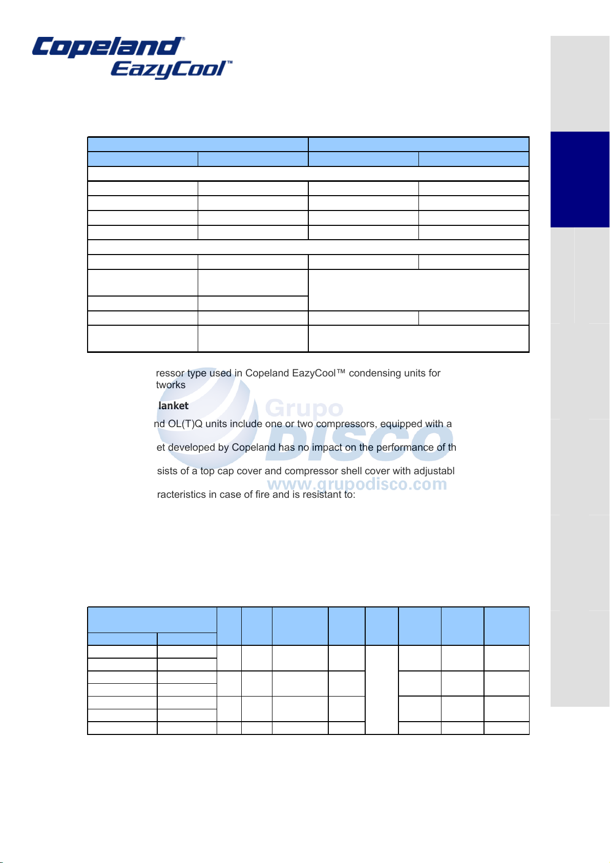
Table 2: Compressor type used in Copeland EazyCool™ condensing units for
refrigeration networks
2.6.2 Sound Blanket
(*)
1 x ZB30KCE-TFD-551
1 X ZBD45KCE-TFD-250
(*)
1 x ZB45KCE-TFD-551
Safety
Instructions
Product
Description
Installation Electrical
Connection
The OM(T)Q and OL(T)Q units include one or two compressors, equipped with a sound
jacket.
The sound jacket developed by Copeland has no impact on the performance of the
compressor.
The design consists of a top cap cover and compressor shell cover with adjustable Velcro
system.
It has good characteristics in case of fire and is resistant to:
Mineral and Polyolester oil
Refrigerants R22/R404A
Temperature up to 150°C
Water
2.6.3 Condenser Fan(s)
The condensers of the OM (T) Q & OL (T) Q units for refrigeration networks are equipped
with single-phase fans, with low speed (910 rpm) 6 pole single-phase motor.
ø
420
500
420
Voltage
V/ph/Hz
220-240
1~50
Power
input (W)
145
290
145
Current
input (A)
0.67
1.4
0.67
Winding
resistance
Ohm (Ω)
Condensing unit
Medium Temp Low Temp
OMQ-56-Nxx OLQ-24V-Nxx
OMQ-75-Nxx OLQ-33V-Nxx
OMQ-92-Nxx OLQ-40V-Nxx
OMQ-110-Nxx OLQ-48V-Nxx
OMTQ-60(D)-Nxx OLTQ-26V-Nxx
OMTQ-76-Nxx
OMTQ-90(D)-Nxx OLTQ-36V-Nxx 2 301 8µF-400V 500 290 1.4 25
Electrical data @ 50 Hz
N° of
Fan
2
2
2
Fan
Model
145
301
145
Run Capacitor
Capacity
4µF-400V
8µF-400V
4µF-400V
Diameter
(mm)
Table 3: Condenser fan: technical data
70
25
70
Operation
Starting up &
& Repair
Maintenance
Disposal
Dismantling &
C6.1.4/0305/E 6 Part no: 3136433
Condensing Unit For Refrigeration Networks
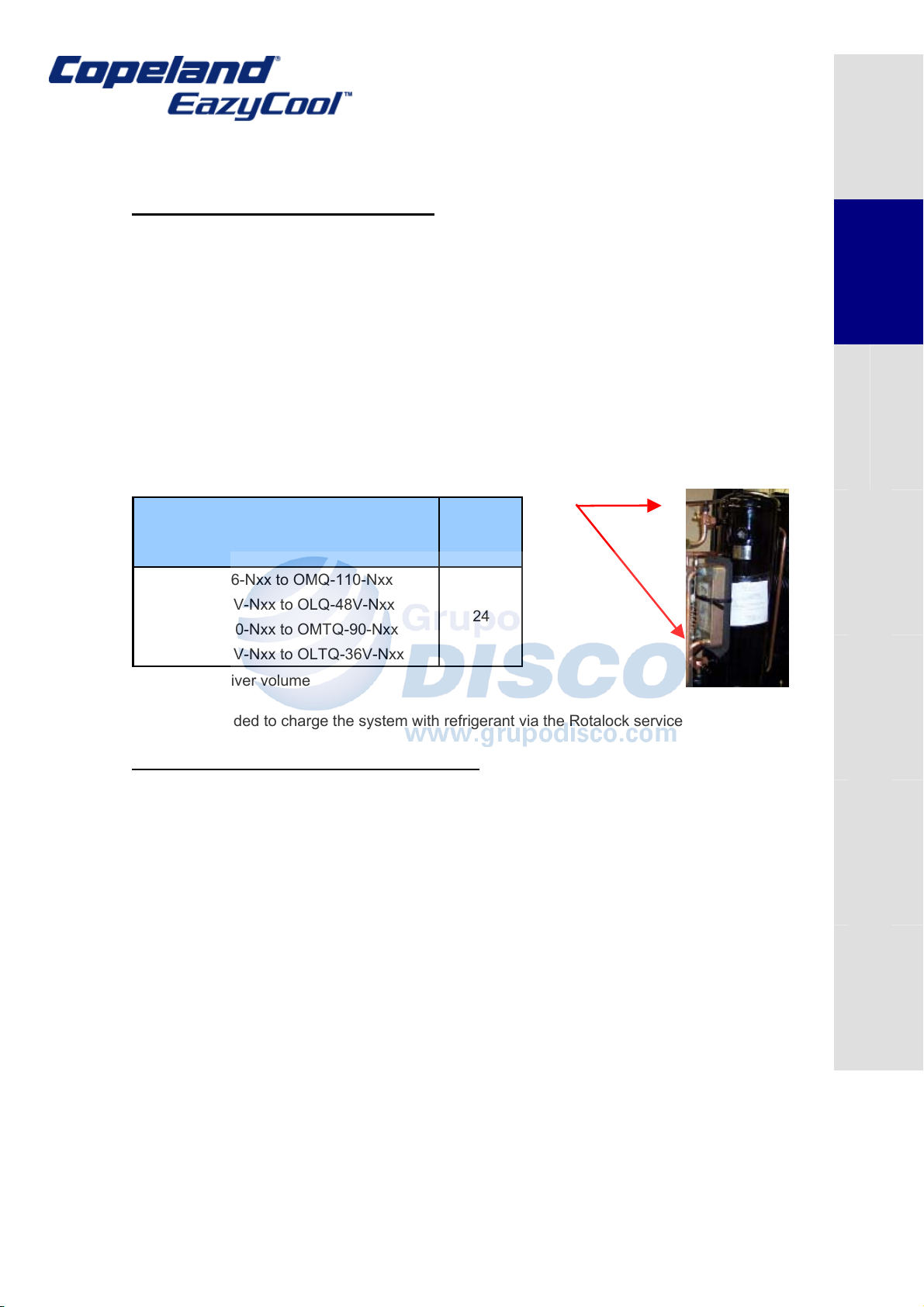
2.6.4 Liquid receiver
Liquid receiver for 2 unit network system
Master and Slave units for 2-unit network configuration are equipped with a liquid
receiver.
The liquid receivers are equipped with:
Rotalock service valves for connection of a liquid level equalisation line as well as
a gas pressure equalisation line between the receivers to ensure equal liquid
levels in both receivers. Both lines are partly pre-installed and protrude at the rear
of the units.
Rotalock service valve on top of the receiver for liquid outlet line.
3/8’’–14 NPTF connection for relief valve. Maximum allowable working pressure -
MAWP 33 Bar
Fitting a pressure relief device according to standard EN378-2 is the responsibility of the
installer.
Rotalock service valve
Model Type
OMQ-56-Nxx to OMQ-110-Nxx
OLQ-24V-Nxx to OLQ-48V-Nxx
OMTQ-60-Nxx to OMTQ-90-Nxx
OLTQ-26V-Nxx to OLTQ-36V-Nxx
Receiver
volume
l
24
Safety
Instructions
Product
Description
Installation Electrical
Connection
Table 4: Receiver volume
It is recommended to charge the system with refrigerant via the Rotalock service valves.
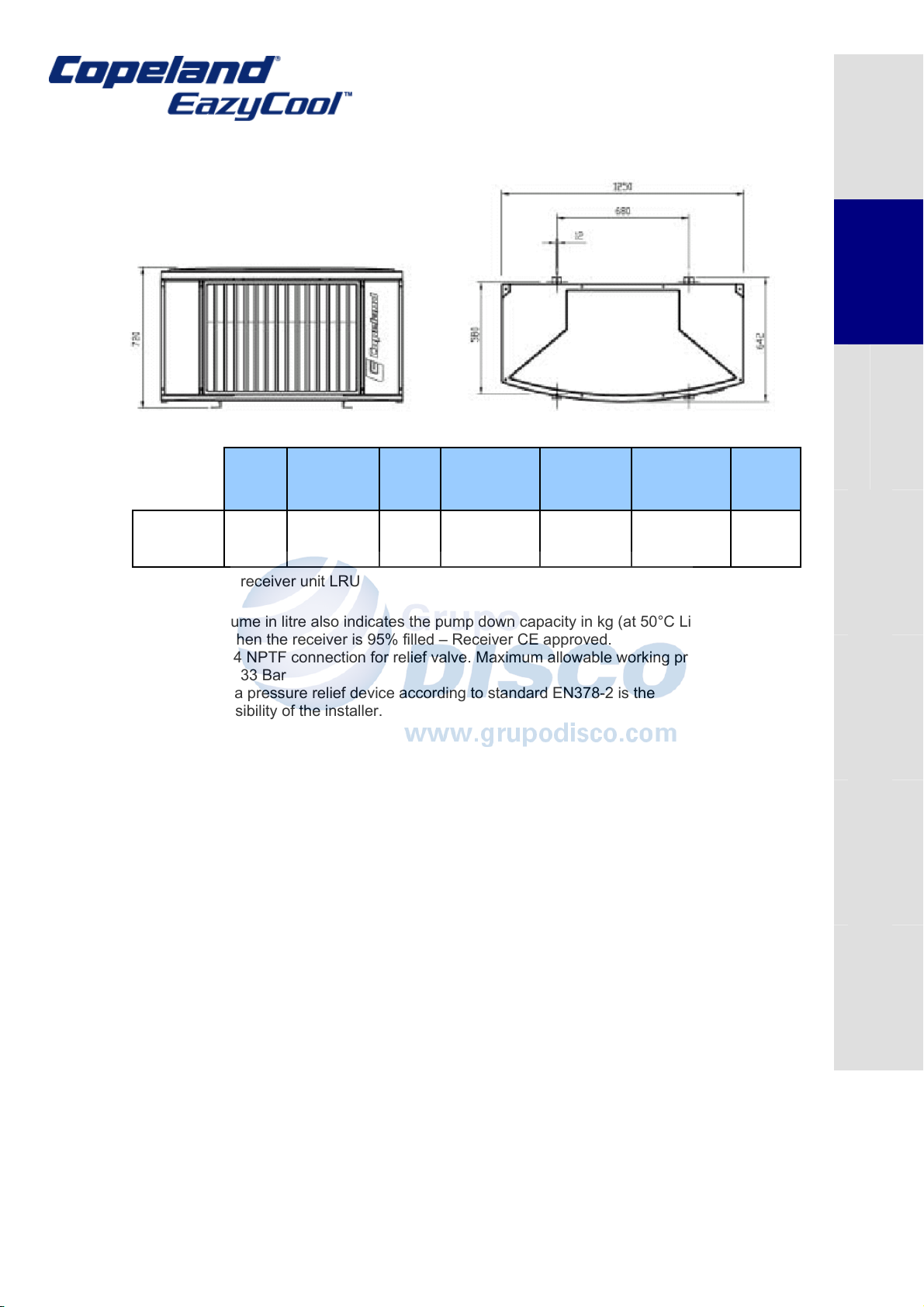
Liquid receiver for 3 and 4 unit network system
With larger systems (refrigeration systems requiring 3 or 4 units in a network) a remote
liquid receiver should be used. The condensing unit models for systems with remote
receivers are provided without liquid receiver. The condenser liquid outlet line protrudes
from the rear of the unit to allow an easy connection to a remote liquid receiver.
Copeland offers a LRU (Liquid Receiver Unit), which contains a 90 litres liquid receiver
for remote use with filter drier, sight glass with moisture indicator and ball valves for liquid
inlet and outlet. If a larger receiver is required, this should be obtained from a third party.
Operation
Starting up &
& Repair
Maintenance
Disposal
Dismantling &
C6.1.4/0305/E 7 Part no: 3136433
Condensing Unit For Refrigeration Networks
The LRU collects liquid refrigerant from each condenser in a network. It has a single
liquid inlet and outlet line.
Safety
Instructions
Product
Description
Receiver Depth / Width Height Dimensions Liquid Liquid Weight
Capacity T/B H (holes) Inlet diameter Outlet diameter Net/Gross
1)
l
Liquid
Receiver
Unit
Table 5: Liquid receiver unit LRU
1)
Receiver volume in litre also indicates the pump down capacity in kg (at 50°C Liquid
temperature) when the receiver is 95% filled – Receiver CE approved.
1/2’’–14 NPTF connection for relief valve. Maximum allowable working pressure -
MAWP 33 Bar
Fitting a pressure relief device according to standard EN378-2 is the
responsibility of the installer.
2.6.5 Electrical box: components
All electrical components are pre-wired into the panel.
This panel contains:
Compressor contactor(s)
Fuse
Terminal blocks
DIN rail mounted terminals
Electronic controller
Fan Speed controller
Alarm relays
90 630 / 1250 720 680 x 580 (12) 1 5/8 1 3/8 120 / 142
mm mm b x t,(ø mm) ø (inch) ø (inch) kg
Installation Electrical
Connection
Operation
Starting up &
& Repair
Maintenance
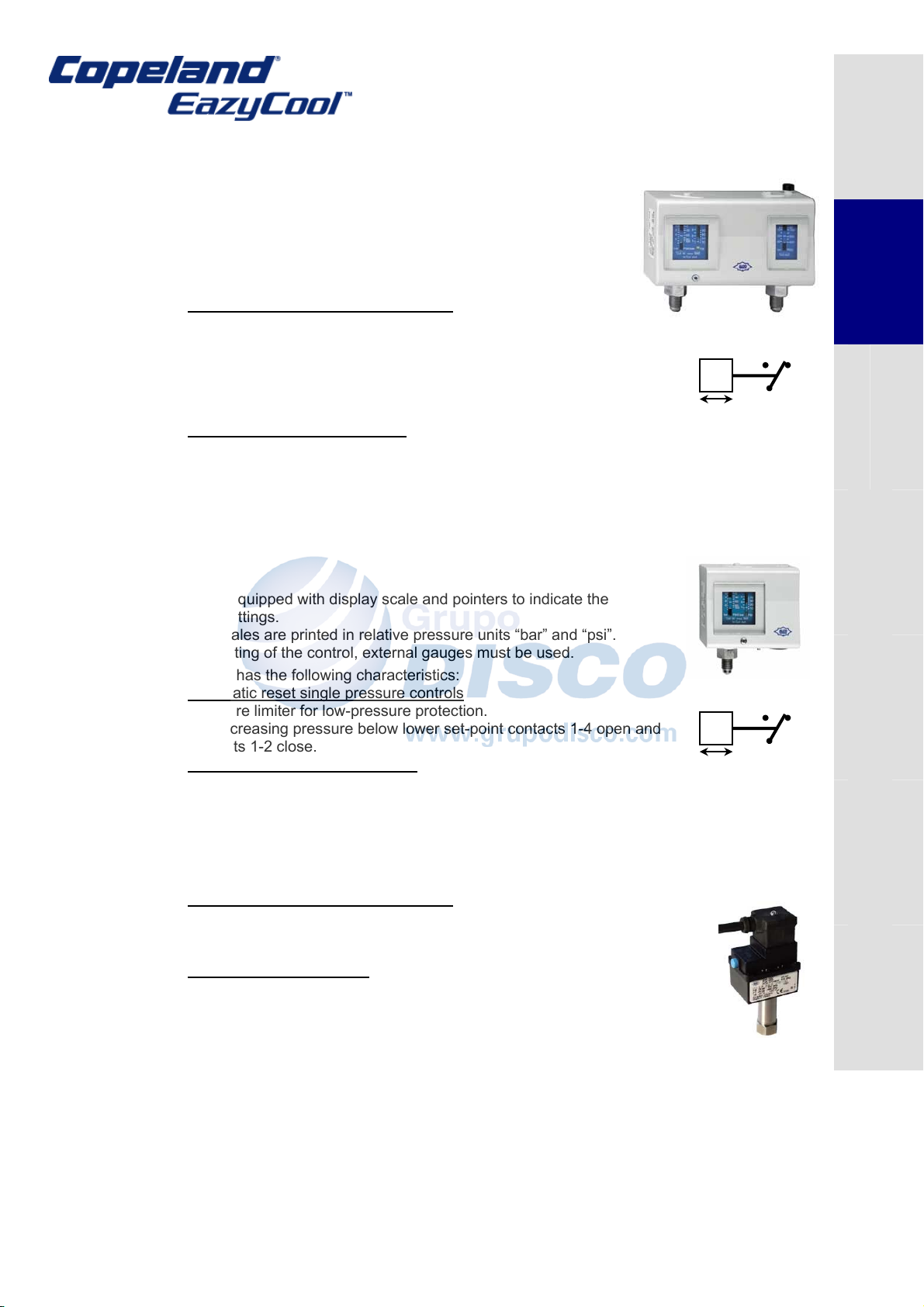
2.6.6 Pressure switch
All single compressor Copeland EazyCool™ condensing units for refrigeration networks
are equipped with:
Single low pressure switch with automatic reset: ALCO PS1-W3A
Electronic Condensing Unit Controller with HP and LP pressure transmitters
All two-compressor Copeland EazyCool™ condensing units for Refrigeration Network are
equipped with:
Single low pressure switch with automatic reset: ALCO PS1-W3A
Two high pressure switches ALCO PS3-WF4-HNS
Electronic Condensing Unit Controller with HP and LP pressure transmitters
C6.1.4/0305/E 8 Part no: 3136433
Dismantling &
Disposal
+
+
Condensing Unit For Refrigeration Networks
1) PS2-W7A: Alco Controls® dual pressure switch with automatic reset (fo r single
compressor unit)
The switch is equipped with display scale and pointers to indicate the
approximate settings. The display scales are printed in relative pressure
units “bar” and “psi”.
For precise setting of the control, external gauges must be used.
The PS2-W7A has the following characteristics:
Automatic reset dual pressure controls
Combined pressure limiter for low pressure / high-pressure
protection.
On pressure rise above the upper setpoint, contacts 1-2 open and
contacts 1-4 close.
On decreasing pressure below lower setpoint contacts 1-4 open and
contacts 1-2 close.
Adjustable dual pressure switch
Setpoint adjustment range: LP (left) = -0.5 to 7 bar and HP (right) = 6 to 31 bar.
Differential adjustment range: LP = 0,5 to 5 bar, HP = 4 bar.
Factory setting: LP = 3,5 / 4,5 bar, HP = 20 bar.
2) PS1-W3A: Alco Controls single low pressure switch with automatic
reset
The control is equipped with display scale and pointers to indicate the
approximate settings.
The display scales are printed in relative pressure units “bar” and “psi”.
For precise setting of the control, external gauges must be used.
The PS1-W3A has the following characteristics:
Automatic reset single pressure controls
Pressure limiter for low-pressure protection.
On decreasing pressure below lower set-point contacts 1-4 open and
contacts 1-2 close.
Adjustable single pressure switch
Setpoint adjustment range: = -0.5 to 7 bar.
Differential adjustment range: = 0,5 to 5 bar.
Factory setting: = 3,5 / 4,5 bar.
3) PS3-WF4-HNS: Alco Controls high pressure switch with an automatic reset
Automatic reset single pressure switch
Pressure limiter for high-pressure protection.
Switches from 1-2 to 1-4 on rising pressure and from 1-4 to 1-2 on falling
pressure.
Fixed switch point settings
Cut-out point: 22 bar
Cut-in point: 26.2 bar.
p
-
p
-
2 4
1
2 4
1
Safety
Instructions
Product
Description
Installation Electrical
Connection
Operation
Starting up &
& Repair
Maintenance
Disposal
Dismantling &
C6.1.4/0305/E 9 Part no: 3136433
Condensing Unit For Refrigeration Networks
4) PT3 Pressure Transmitter (Alco Controls)
Two compressor-condensing units are equipped with HP and LP pressure transmitters
that are connected to the EC2 electronic controller.
The EC2 controller description and programming instructions are available in the
corresponding guideline (C6.1.5/E, Part no: 3136444) which is shipped with the units. It
is also available for download on www.eCopeland.com.
An Alco PT3-30A pressure transmitter is used at the high-pressure part of the system.
An Alco PT3-07A pressure controller is used at the low-pressure part of the system.
The PT3 pressure transmitter converts a pressure into a linear electrical 4-20 mA
current output signal. The heart of the transmitter is a piezo resistive chip enclosed in an
oil capsule.
Features:
Pressure sensitive piezo-based cell with strong primary output signal for precise
and sound-free operation
Vibration and pulsation resistant
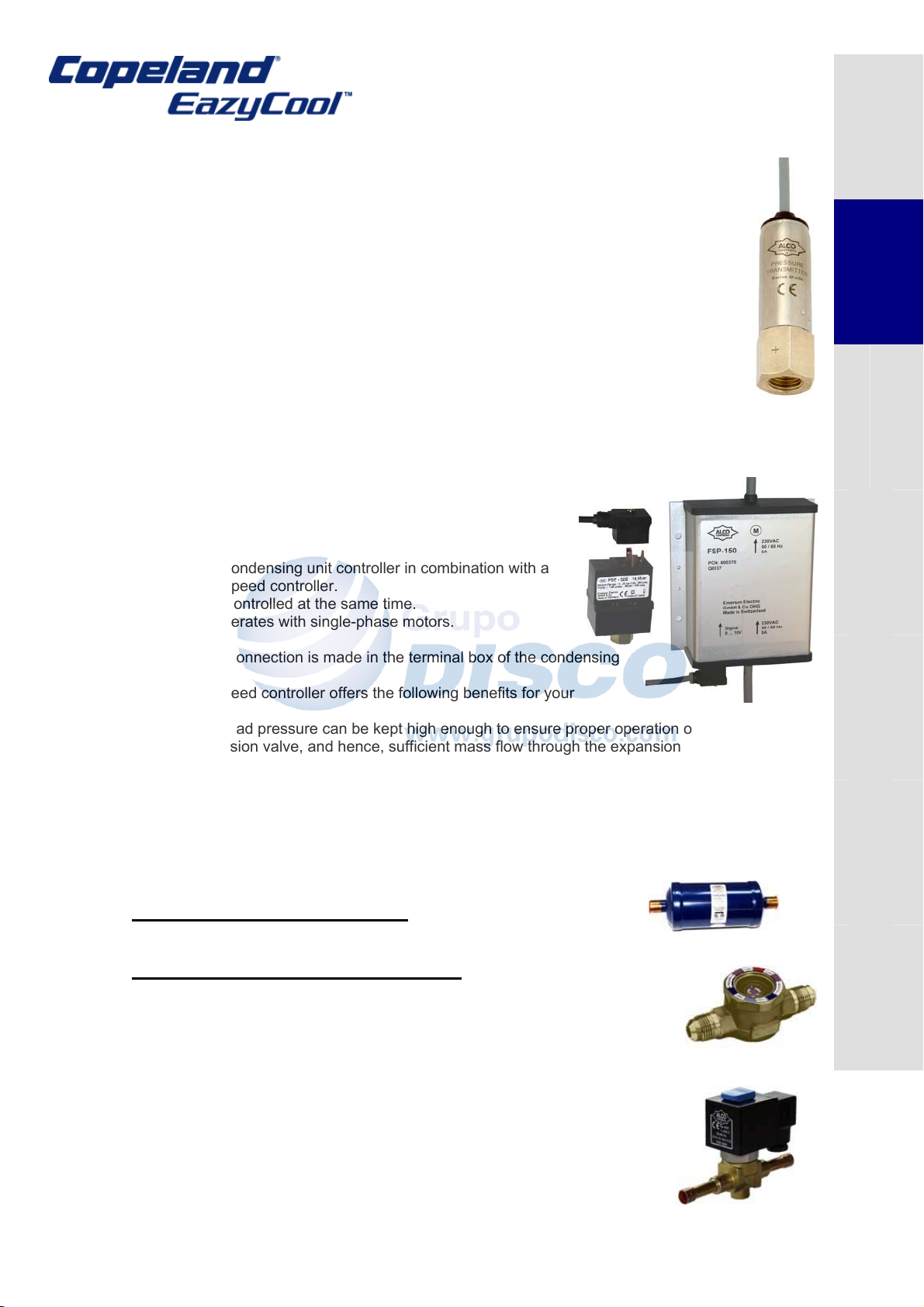
2.6.7 Fan speed controller (FSP150) Alco Controls
An electronic speed control is fitted as standard in units
suitable for refrigeration networks. It controls the speed of the
fans based on condenser pressure. Fan speed is controlled by
the EC2-551 condensing unit controller in combination with a
FSP-150 fan speed controller.
Two fans are controlled at the same time.
The control operates with single-phase motors.
The electrical connection is made in the terminal box of the condensing
unit.
Using a fan speed controller offers the following benefits for your
application:
The head pressure can be kept high enough to ensure proper operation of the
expansion valve, and hence, sufficient mass flow through the expansion valve to
feed the evaporator. This maintains the required cooling capacity and avoids a
drop of evaporator temperature.
The sound level of fan motors can be kept at a minimum by avoiding the
permanent on/off cycling of the fan motor. The Alco Controls fan speed control
can be delivered with the Copeland units or as a separate accessory.
Safety
Instructions
Product
Description
Installation Electrical
Connection
Operation
Starting up &
2.6.8 Liquid line equipment (only for 2 unit network configuration)
a) Filter drier Alco Controls ADK-plus
ADK-plus liquid line filter-drier is for new installation or after service.
Optimum blend of molecular sieve and activated alumina
b) Liquid sight glass Alco Controls AMI 1SS*
The AMI series of moisture indicator is designed to monitor the moisture
content within the liquid line of a refrigeration system. When the line is empty
of liquid, circles may be seen in the glass. However, when the liquid refrigerant
touches the glass, the circles disappear indicating the system is fully charged.
2.6.9 Liquid line solenoid valve (for low temp. model only) Alco
Controls 200 RBT 5
This is used in low temperature with 2, 3 & 4 unit network systems
Compact size
Snap-on clip for attaching solenoid coils
∆p minimum = 0,05 bar
C6.1.4/0305/E 10 Part no: 3136433
Maintenance
Dismantling &
& Repair
Disposal
Loading...