

Page 1
Instruction Sheet
PA-00376
October 2014
Oil Separators / A-W, A-F, A-WZ
Oil Separators / A-W, A-F, A-WZ
General Information
The function of an oil separator is to separate oil from the
hot gas in the discharge line and return it to the compressor
crankcase or to the oil reservoir in systems with multiple
compressors.
Application
• Multiple compressor racks for supermarkets and air
conditioning
• Systems with long refrigerant lines
• Systems with inherent oil return problems
• Ultra-low temperature systems
• For use with HCFCs, HFCs and their lubricants
Features
• Hermetic welded or accessible bolted ange construction.
• Solid copper connections
• Corrosion resistant paint
Specications
• A-W, A-F Maximum working pressure: 450 psig
• A-WZ Maximum working pressure: 600 psig
Safety Instructions
• Read installation instructions thoroughly. Failure to
comply can result in device failure, system damage or
personal injury.
• It is intended to be installed by persons having the
appropriate knowledge and skill. Before attempting to
install, make sure pressure in system is brought to and
remains at atmospheric pressure.
• Do not release any refrigerant into the atmosphere.
• Do not use any other uid media without prior approval
of Emerson Climate Technologies. Use of uid not listed
could result in change of hazard category of the product
and consequently change of conformity assessment
requirement for product in accordance with European
pressure equipment directive 97123/EC or countries
where applied.
• In a severely contaminated system, avoid breathing acid
vapor and avoid contact with skin from contaminated
refrigerant lubricants. Failure to do so could result in injury.
• The oil separator must be used only for the purpose it is
designed for.
Mounting Location
The oil separator should be installed as close as possible to the
compressor(s) in the main discharge line but after any installed
mufer or vibration absorber.
Please make sure piping is adequately supported to prevent
excessive vibration and stress on the connections.
Caution: Prevent the migration of liquid refrigerant back
into the oil separator shell during off-cycles by one of the
following recommendations:
- Install the oil separator in a location where it is higher than
the condenser.
- If the oil separator is located slightly lower than the
condenser, install the line from the oil separator to the
condenser at higher level than the condenser and with
a downward slope into the condenser inlet connection.
- In systems where the condenser is located higher than the
oil separator, it is recommended to use a check valve at the
outlet of oil separator.
Installation
Before proceeding with the installation, the oil separator
must be charged with a certain amount of oil in order to actuate
the oat mechanism immediately after start-up. Use the same
type of oil as in the compressor.
- 0.5 liter (17 oz.) initial oil charge for A-W, A-F, A-WZ 4 in.
diameter models
- 0.6 liter (20 oz.) initial oil charge for A-W, A-F 6 in.
diameter models.
- 0.74 liter (25 oz.) initial oil charge for A-WZ 6 in.
diameter models.
• The oil must be charged through the outlet connection
• The oil separator shell must be mounted securely in a
vertical position.
Warning
Protect the oil separator against vibration and gas pulsation
generated by the compressor. Install a vibration absorber and
mufer between the compressor and the oil separator.
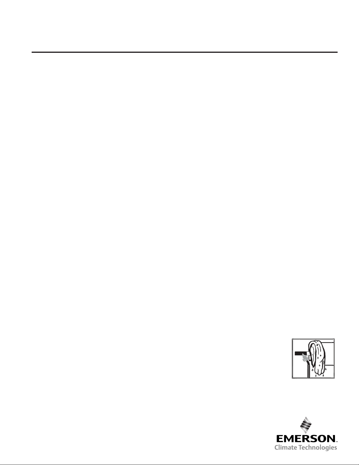
• When brazing, direct the ame away from shell. Use wet
rags or other suitable heat protection to prevent damage to
the paint surfaces adjacent to the ttings.
• Use the correct temperature for brazing copper to copper
as the ttings of the shell are solid copper. Do not exceed
675°C ame temperature.
• Purging dry nitrogen through the lines during brazing will
prevent oxide scale (solid particles) from forming
on the inside of the brazed joints. These particles can jam
the oat mechanism and clog the needle valve.
Caution: The oil separator F Type
with a ange cap incorporates a gasket.
Do not exceed 150°C around the ange.
If so, the gasket can be damaged and it
must be replaced. Keep the ange cap
cool during brazing.
• The oil return line (minimum 3/8" or 10 mm) should be
connected to the compressor crankcase or to the oil
reservoir in the systems with multiple compressors.
Page 2

• If the piping results in excessive stress to the joints of the
oil separator, the pipes must be supported by suitable
mounting bracket(s).
Leak Test
• After completion of installation, a pressure test must be
carried out as follows:
- According to EN378 for systems which must comply with
European pressure equipment directive 971231EC.
- To maximum working pressure of systems for others
applications.
Warning
1) Failure to perform a leakage test could result in loss of
refrigerant and personal injury.
• In case of leakage around the ange of the oil separator
(anged type), check the gasket and the tightness of bolts
with 35 Nm torque. A spare gasket is supplied with each
anged type oil separator.
• After leakage test, the unused spare gasket should be
saved for future service.
Operation
• After leakage test, start system. The oil level in the
compressor crankcase and in the oil reservoir must be
observed after start-up, the rst few hours of operation
and a couple days later. The new refrigerant will mix with
some oil. There may be a small portion of oil trapped in
the system.
• The oil separator removes the excess oil, but this may not
be returned to the compressor crankcase immediately.
In normal operation, the oil return line to the compressor
crankcase or to the oil reservoir will be alternately hot
and cold. This is caused by opening and closing of the
needle valve via lifting and lowering the oat mechanism.
• In some outdoor installations, the oil separator may be
subject to low ambient temperature conditions. In this
case, it must be insulated to prevent the condensation
of any refrigerant it passes. If condensed, the liquid
refrigerant could be passed through the return line into the
compressor crankcase, foaming the oil which could result
in lubrication issues.
• Oil separators perform best when operating at or near
the compressor discharge temperature. It is advisable to
insulate the oil separator shell.
Warning
During operation of the system, the shells have a high surface
temperature.
Service Tips
• Oil separator F Types are equipped with a ange and can be
opened for cleaning. Always use a new gasket and tighten
the bolts to 35 Nm. torque.
• The external surface of the shells are coated with epoxy
paint for optimum protection against corrosion. The external
surface of the shell should be checked as per EN-378
during routine inspection and service.
EmersonClimate.com/FlowControls
Technical Support: 1-866-625-8416
PA-00376 R1 (10/14) Emerson is a trademark of Emerson Electric Co. ©2014 Emerson Climate Technologies, Inc. All rights reserved.
 Loading...