Emerson 5500, A5510 User Manual

Installation Manual
5500 Series, Catalog A5510
software version 5
Warnings ................................................................................................... i
Welcome............................................................................................................. ii
1 General
Overview & Technical Specifications .............................................................. 1-1
2 Mounting
Installation ....................................................................................................... 2-1
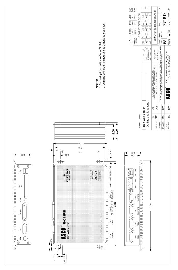
Outline and mounting drawing.................................................................. 771812
3 Connections
ATS network, phone line, power ..................................................................... 3-1
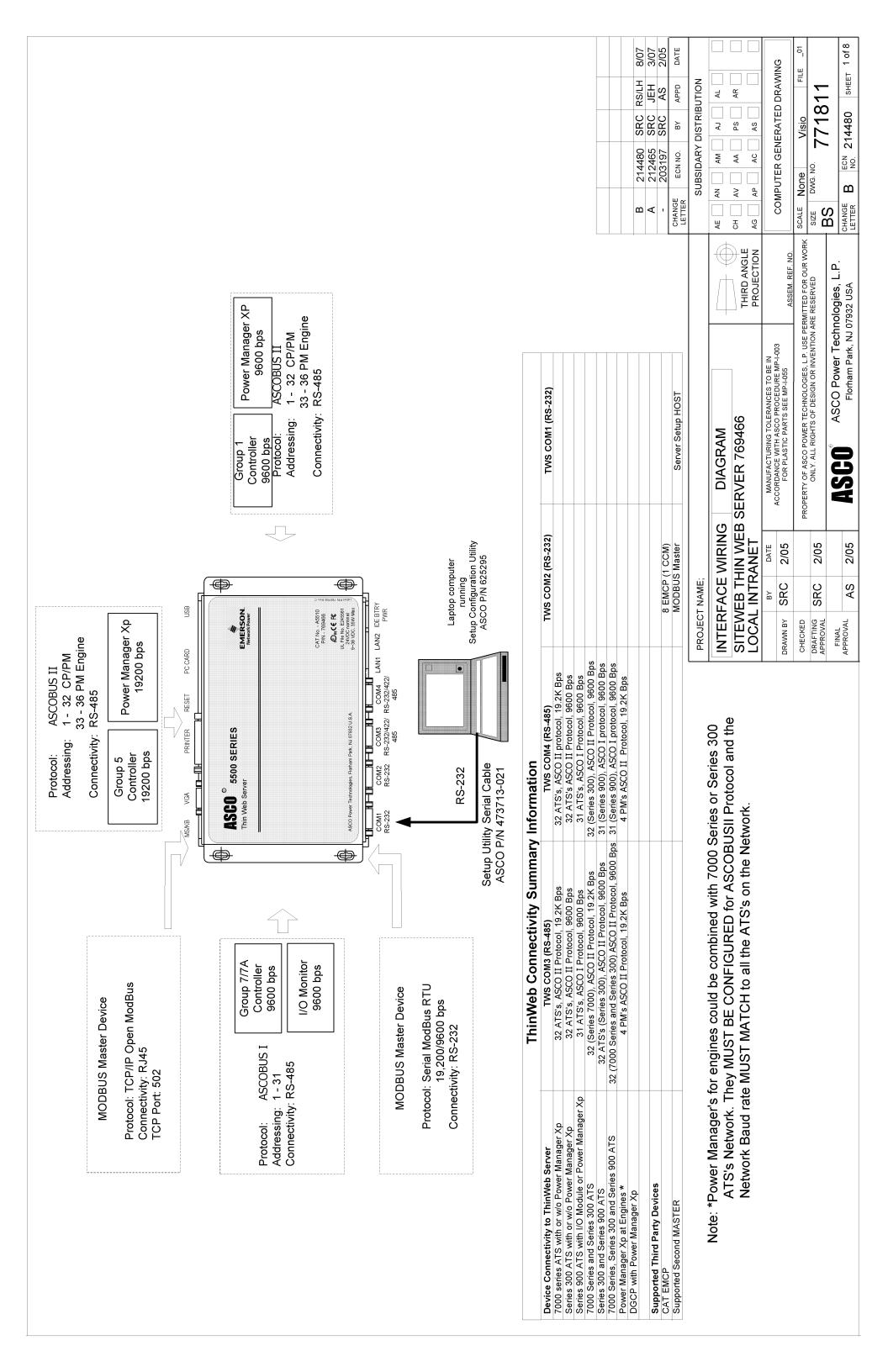
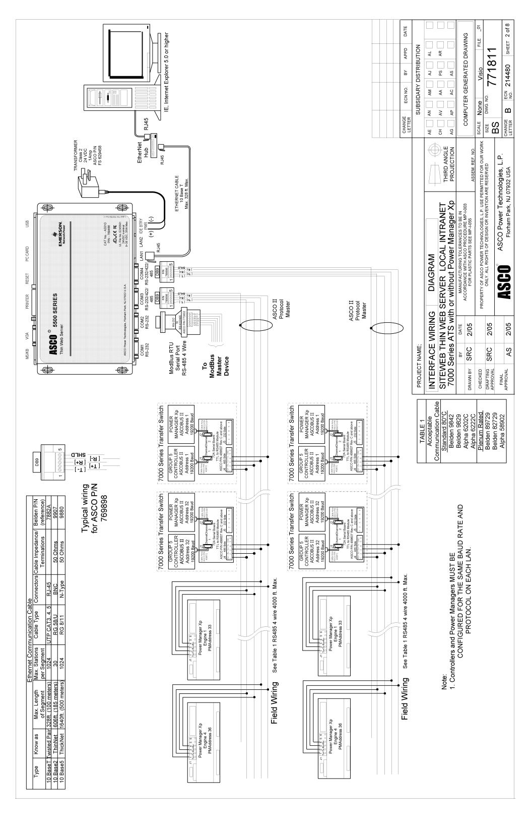
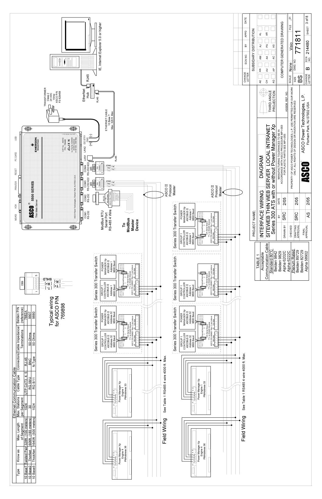
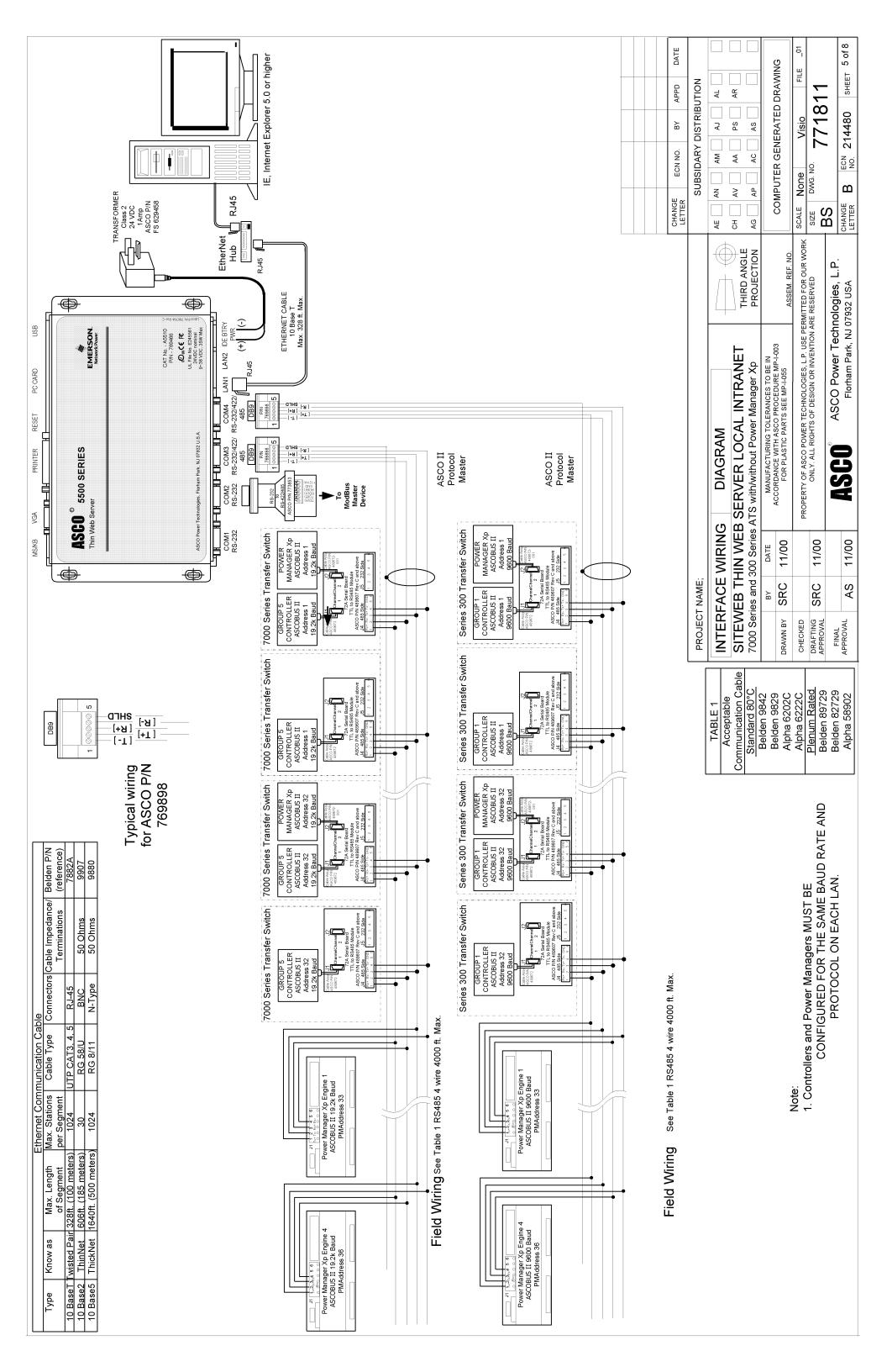
Interface wiring diagram ........................................................................... 771811
4 Setup Procedure
How to install the Thin Web Server Setup program ........................................ 4-1
How to start and setup the TWS software through serial connection ............. 4-3
Uninstalling the program.................................................................................. 4-6
How to Establish Communication with the TWS via Ethernet connection ......4-7
5 File Management Utilities
How to copy, delete, and view files in the Thin Web Server ........................... 5-1
6 SSL Certificate
How to install SSL certificate and private key files.......................................... 6-1
7 Connectivity Module Configuration
How to add configuration setting for a Connectivity Module ........................... 7-1
8 Client Settings
How to create an Ethernet TCP/IP network connection.................................. 8-1
Troubleshooting ..................................................................................................... end
Appendix Communication Address Forms ...............................................in the back
Index ..................................................................................................................last page
381333-277 F
50 Hanover Rd, Florham Park, NJ 07932-1591 USA
Call 1 800 800-2726 (ASC0) for sales or service www.ascopower.com
Thin Web Server Warnings
The ASCO 5500 Catalog A5510 Thin Web Server (TWS) provides real-time monitoring and control of ASCO Automatic Transfer Switches and engine­generator sets over the Internet or an Intranet. These precautions must be followed by all users:
WARNING
Be sure that Users to whom you give access are knowledgeable enough to have control of load transfer and of the generator.
WARNING
Verify that conditions are safe for load transfer before you transfer or retransfer an Automatic Transfer Switch (ATS).
WARNING
Fill in the Communication Address Forms in the back of this manual. Be sure that you enter correct information about each Automatic Transfer Switch and Power Manager and that address recorded on the Communication Address Forms corresponds with the address set in the ATS’s Controller and Power Manager.
© ASCO Power Technologies, L.P. 2008 Microsoft and Windows are registered trademarks of Microsoft Corporation. All Rights Reserved.
Welcome Thin Web Server
Who Should Use this Installation Manual
This installation manual for the Thin Web Server should be used to assist individuals who will:
• install and connect the Thin Web Server
• configure the Thin Web Server with the setup program
Prerequisites A working knowledge of Windows® 2000 or XP is necessary to use this
software. Use of a mouse is assumed and that you are right handed. If you are left handed see personalizing Windows (switch mouse buttons) in Windows Help Index and switch the left and right mouse buttons.
Click means to press and release the left mouse button once when
the cursor is on the appropriate location on the screen.
Double click means to quickly press and release left mouse twice
when the cursor is on the appropriate location on the screen.
Right Click means to press and release the right mouse once when
the cursor is on the appropriate location on the screen.
Enter means to press the Enter key on the PC keyboard.
Important information To properly set up the software, you will need the nameplate data and other that you will need information from all your Automatic Transfer Switches (up to 64) including:
• ATS Name (your designation for the ATS)
• ATS Address (set in each Controller, Comm. Interface Module, or Acc. 72A)
• Voltage Rating, Ampere Rating, and number of Poles for each ATS
• Catalog No. and Serial No. of each ATS
• Type of ATS (ATS or ATS/BP [ATS with bypass-isolation switch])
• Power Manager Address (set in each Power Manager or Data Monitor)
Manuals that Catalog 214A700 & 214A701 Data Monitor Operator’s Manual 381333-143 you may need Catalog 5200 & 5200T Power Manager Operator’s Manual 381333-192
Catalog 5220 & 5220T Power Manager Xp Operator’s Manual 381333-199
7000 Series ATS Group 5 Controller User’s Guide 381333-126 Catalog 5110 Serial Module Installation Manual 381333-240 Series 300 ATS Communication Interface Module Instructions 381339-189 ASCO 940, 962, 436, 434,447, 448 ATS Acc. 72A Instructions 381339-172
Tip
Ö Communication Address forms are included at the back to help you fill in
needed information on your ATSs and Power Managers / Data Monitors.
User’s Guide Refer to Power Monitoring & Control System User’s Guide 381333-276D for version 5.
1-1 Overview, Specifications, Ground Connection Thin Web Server
Overview
The ASCO 5500 Series Catalog A5510 Thin Web Server (TWS) provides real-time monitoring and control of ASCO Automatic Transfer Switches and engine-generator sets over the Internet or an intranet. The TWS also logs critical alarms and analog information.
The TWS can be used with ASCO 4000 & 7000 Series and Series 300 Automatic Transfer Switches that have Accessory 72A Communication Interface Modules.
Specifications
Power Requirements: 24 Vdc nominal (9-36 Vdc)
35 Watts max.
Dimensions: 6” H, 10” W, 2” D
(15.2 cm, 25.5 cm, 5 cm)
Weight: 3.5 lb. (1.6 kg)
Operating Temperature: 14 to 122° F (-10 to 50° C) at 5-85% relative humidity
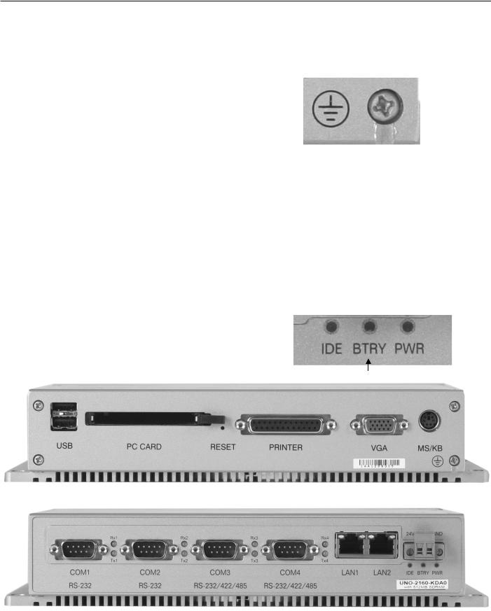
Lights: power, IDE, & internal low
battery alarm (RAM backup)
LAN Ports: two 10/100 base T RJ45
USB Ports: two USB 1.1
Serial Ports (DB-9): two RS-232 and
two RS-232/422/485
Ground Connection
The TWS has a chassis ground point on the top left corner. Back out the screw and connect a braided lead as short as possible to earth ground.
When the TWS is mounted on a door, a conductive strap must be used between the enclosure and the door. This connection provides proper grounding which does not rely upon the door hinges.
Backup Battery - type BR2032
The SRAM memory is retained by an internal backup battery. If the battery light BTRY comes on, this battery must be replaced. The battery is located on the left side of the main circuit board. De-energize all power first. Then remove the bottom four screws and slide the the cover down and off. Use 3 V lithium type BR2032 only substitute.
Low battery light
; do not
top view
bottom view
Thin Web Server Mounting
Mount the Thin Web Server
Refer to the outline and mounting drawing 771812 and mount the Thin Web Server vertically to a flat surface in a clean and dry location. If it is mounted in an enclosure it must provide adequate ventilation for cooling.
Four 3/16” diameter mounting holes are provided in the back mounting plate. Securely mount the Thin Web Server as shown on the drawing.
2-1
Thin Web Server Connections
Connect the ATS Network
Refer to Interface Wiring Diagram 771811. Use only the recommended communication cable listed below to connect the ATS network to the Thin Web Server.
Standard 80º C Plenum Rated Belden 1419A, 9842, or 9829 Belden 89729 or 82729 Alpha 6202C or 6222C Alpha 58902
Connect the Power
Refer to Interface Wiring Diagram 711811. Use a UL-Approved Class 2, 24 VDC nominal power supply (plug-in transformer 120 VAC to 24 VDC, 1 amp.; ASCO part no. 629458). Connect it to the Phoenix connector (bottom right).
3-1
Thin Web Server Setup Program – Serial Connection
Minimum PC Requirements for Setup and Browser Programs
The Thin Web Server requires the following minimum system configuration for the setup and browser program for serial connection:
• Microsoft® Windows® 2000 or XP operating system
• Personal computer with Pentium™ 4 2 GHz or higher processor
• CD-ROM drive
• Serial Port (RS-232), Ethernet Port (RJ-45)
How to Install the Setup Program for Serial Connection
The Thin Web Server Setup program on the CD-ROM must be installed on the PC or notebook PC that is temporarily connected to the Thin Web Server. The setup.exe program takes you through the installation with on- screen instructions.
Note: Windows® may require Administration rights to install this software.
1. Load the CD into the PC’s CD-ROM drive.
The PC should automatically launch the setup.exe file (if the PC is set-up for autorun). If the installation does not automatically, click Start on the taskbar, then choose Run from the Start menu.
In the dialog box type the filename setup.exe. Use (your CD drive letter):\setup.exe (e:\setup.exe for example). Click OK.
The Thinweb Server Setup Program logo
displays during installation process.
2. The Welcome screen displays after the CD is
read.
To proceed click Next to continue or click
Cancel to quit.
Continued on next page Î.
4-1
start
4-2
Setup Program – Serial Connection Thin Web Server
3. The Choose Destination Location screen displays.
Use the default destination directory.
Click Next.
4. The Select Program Folders screen displays.
Use the default directory in the Program Folder.
Click Next.
5. The Copying Windows Systems files … dialog box displays.
These screens show you the actual installation status
6. The Setup Complete screen displays.
Click Finish. Remove the CD-ROM
Keep it in a safe place along with the Serial number
You might consider restarting Windows to initialize the system
before running the software.
Notice that after start-up of Windows which you can double click to launch the ThinWeb Server setup
and return it to its case.
the icon is on the desktop
program. (proceed to next page)
Thin Web Server Setup Program – Serial Connection
How to start and setup the Thin Web Server software
After installing the Thin Web Setup Program start the Thin Web Server software and set it up.
1. Double click the icon on the Windows desktop.
2. The Port Config tab displays first. Work with your net­work administrator to set up the server either for an inter­net or an intranet application. Enter the Ethernet TCP/IP information and outgoing mail server (SMTP). If email authentication must be enabled (ask your administrator), click Authentication Enabled and fill in the Username and Password.
3. Click the Security tab. By default the server is set as an
HTTP & HTTPS server. A default certificate name &
key
name is shown. Use this default and click Next. If not, make sure the files are installed in the server using the Server File Management Utility available in the
program.
4. Click the User Access Configuration lower tab. Enter
up to 5 Users (include yourself), their Passwords, and
their Levels. (you are level 3). The Access Levels are:
1 is monitor only (data page viewing only) 2 is monitor and control (can transfer ATS loads) 3 is administrator (assigns users and able to
Be sure that the Users to whom you give control access
(levels 2 or 3) are knowledgeable enough to have
control of load transfer and of the generator(s).
5. Click the Alarms tab. Click the ATS Setting lower tab. Select the ATS status events that you want reported by clicking the boxes next to the items under ATS Alarm Selection (shown below).
continued on the next page
change TWS configuration settings)
4-3
CAUTION
Ö
4-4
Setup Program – Serial Connection Thin Web Server
6. Click the Email Address lower tab. Then enter the e-mail addresses (up to 5) of the persons whom you want notified of the selected alarms. Double check each e-mail address displayed in the five text boxes to verify that it has been typed correctly.
Note: Make sure outgoing mailserver is configured properly and working. This functionality can be tested with third party e-mail testing programs.
7. Click the ATS Power Manager Setting lower tab. The Network 1 Power Managers (addresses) are displayed first. For each Power Manager (PM) address click the drop-down arrow and select the appropriate icon number associated with the PM. If a Power Manager:
- is with an ATS, select icon 1.
- is with a circuit breaker, select icon 3 or 4.
associated with an ATS or a CB, select icon 2.
continued on the next page
Ö
Alarms - Email Address
- is not Then click View Network 2 Settings and select icons for those PMs.
8. Click the Engine PM Details lower tab. Network 1 & 2 Engine Power Manager (addresses 33-36) are displayed. Enter a Description and Location for each PM. Then select the appropriate icon associated with each PM. Select if device is associated with CCM, EGCP, or both.
9. Click the Engine Power Manager Setting lower tab. Select the check boxes Status Inputs and/or Discrete Outputs that you want included in alarms monitoring.
Alarms - ATS Power Manager Setting
Alarms - Engine PM Details
Alarms - Engine Power Manager Setting
Thin Web Server Setup Program – Serial Connection
10. Click the Logging tab. You can enable or disable historical data logging & alarm logging and change
their default update interval.
; Historical data logging enabled or disabled flag Historical data logging update interval (15 to 30
minutes)
Default frequency is 30 minutes
; Alarm logging enabled or disabled flag Alarms logging update interval (5 -20 seconds) Default frequency is 5 seconds
11. Click the Company Info tab. Fill in the site information. This information will be displayed at the Thin Web Server home page.
Site Name Company Domain Name Street City State Zip Code Contact Name Contact Phone # Email Address Site Description
12. Click the Protocol tab.
Click the protocol that you want to use for third party device interface. Then select the com port and baud rate to match with the Master device.
13. On the File menu click Save to retain all your settings.
14. On the Communication menu click Upload To Server
to transfer your settings to the ThinWeb Server.
4-5
Ö
PC ThinWeb Server
Be sure that the ThinWeb Server is properly connected to
all devices and that it is powered up.
Be sure that the ThinWeb Server COM1 is connected
to the COM port of the PC running the setup program. A special serial cable is provided.
If a Timed Out error message is displayed, the upload to
the server did not nections of the PC and the ThinWeb Server.
Print config. file or copy it onto a diskette for safekeeping
15. Now check System Configuration as described in the
User’s Guide (correct the date & time if necessary).
occur. Recheck the COM port con-
4-6
Setup Program – Serial Connection Thin Web Server
Un-installing the program
1. Go to the Windows-desktop and click á Start on the taskbar.
2. Click Settings on the menu.
3. Click Control Panel.
4. In the Control Panel window,
double click the Add/Remove Programs icon.
5. In the Add/Remove Programs Properties window find ASCO TSSP on the Install/Uninstall tab.
ASCO TSSP
Click OK to restart.
To start uninstall, select ASCO TSSP and click to proceed. You will be asked to confirm the file deletion process.
If you want to proceed click Yes , otherwise click No to cancel.
6. Click No to All.
7. After the UnInstallShield removes the program it displays
Uninstall successfully completed. Click OK.
8. Close the Add/Remove Programs and Control Panel windows.
9. Restart the PC after this procedure. You do this by going back to
the desktop and click á Start on the taskbar.
10. In the Start menu, click Shut Down. In the
Shut Down
Windows dialog box click ~ Restart the computer.
Thin Web Server Setup – Ethernet Connection
How to Establish Communication with the Thin Web Server via Ethernet Connection
To set up the Thin Web Server via Ethernet connection, follow this procedure.
Required items:
Portable laptop computer with network card, running
Windows Xp, Windows 2000, or Windows NT, and Windows Internet Explorer 5.0 + installed.
Ethernet crossover network cable (part no. 629590-006)
1. Directly connect the specified Ethernet crossover
cable between your laptop’s Ethernet jack and the deenergized Thin Web Server port LAN1 (page 1-1)
2. Refer to the section 8 and select the appropriate
TCP/IP Installation & Configuration instructions for your laptop computer’s operating system. This procedure sets up your laptop computer (if necessary) for network connections and tests communications to the Thin Web Server.
3. After you have confirmed communication with the
Thin Web Server, continue to the next page to view and change the configuration of the Thin Web Server.
Now view and change the configuration (next column)
How to View & Change Configuration Page from the Thin Web Server
To view and change configuration pages on a client computer, follow these steps:
1. Be sure that your computer is connected to the network.
2. Start Microsoft Internet Explorer browser on computer.
3. In the address bar, type in the address of the Thin Web Server, add /config.htm, press Enter :
http://169.254.1.2/config.htm
4. Type in the User name and the Password and click OK.
5. Fill in the IP address, subnet, and gateway.
6. Enter up to 5 Users (include yourself), their Passwords, and their Levels ( you are level 3). The Access Levels are:
1 is monitor only (data page viewing only) 2 is monitor and control (can transfer ATS loads) 3 is administrator (assigns users and able to change
TWS configuration settings)
7. Fill in the Company Information.
8. Click the Protocol Configuration that you want to use for ASCO devices and for third party device interface. If COM4 is being used, check that box.
9. Click Save to retain all your settings !
After saving your settings, close Internet Explorer. Then turn off the Thin Web Server and disconnect the cross-over cable.
NOTE The next time you revisit this page you will have to use the latest IP Address of the system. Hence:
http:// Latest-IP-Address /config.htm
The Thin Web Server must be previously configured using TSSP before you can use this proces
4-7
Thin Web Server File Management Utilities
How to copy, delete, and view files in the Thin Web Server
( to update firmware, to update documentation )
Two file management utilities are included on the install CD. One is for Serial connection and the other is for Ethernet use.
Serial Connection
1. Connect the downloading serial cable between the TWS and your computer. Be sure that the proper COM port property settings are in effect.
2. Double click the icon on the Windows desktop to start the TWS software. On the menu bar click
Communication, then select Connect to the Server. When the
TWS is connected the bottom right corner light turns green Server Connected. On menu bar click Utilities then Server File Management.
3. Choose Ye s on all prompts. Listen for a series of low
beeping sounds after the last prompt (this indicates the TWS is in the debug mode).
4. The Add / Edit File screen displays. Here you will be
able to transfer files from the local computer’s disk/directory (source) to the TWS’s disk (destination).
5. To do this, locate and select the file from your local
computer directory listing (file is highlighted when selected). Then select the target destination path in the TWS where you want the file to be transferred. Choose either C:\ or C:\HTML.
6. Click the Update button to start the process. A DOS
window opens. Let the process complete; do not interrupt it. When finished, the DOS window will close (with a series of beeping sounds).
7. You can review the current directory list of the TWS. To
do this click the Delect File tab (bottom of screen), then click the View Server Disk button to start the process. A DOS window opens. Let the process complete; do not interrupt it. The first page of TWS files displays; press any key to display the next page of files. After the last page, the DOS window will close (with a series of beeping sounds).
8. You can also delete a file from the TWS directory. First,
you should know exactly what and where the location of file that you wish to erase (step 7 helps you verify and locate the file). To erase the file, type in the complete source path and file name in the FileName text box. Two examples are shown below:
Example 1: C:\alarm.bin
This is an alarm log file in the root directory.
Example 2: C:\HTML\yel.gif
This is a file in the HTML subdirectory.
continued on next page
5-1
5-2
File Management Utilities Thin Web Server
9. To start the file delete process click the Delete button once. A DOS window opens. Let the process complete; do not interrupt it. When finished, the DOS window will close (with a series of beeping sounds).
10. When finished, click the Cancel buttons to return to the main screen. On the menu bar click Communication then Disconnect from the Server.
11. Reset the TWS. Insert a pin or paper clip into the hole marked RESET (top center); or disconnect power supply plug to the TWS for 15 seconds, then reconnect it..
Ethernet Connection
1. The computer must be connected to the same network as the TWS. See Section 6, How to create an Ethernet TCP/IP network connection (select either Windows 2000 or XP).
2. Double click the icon on the Windows desktop to start the
CAUTION
Be sure that you are certain of file(s)
to delete in the following procedure.
TWS software. On the menu bar click Communication, then select Connect to the Server. When TWS is connected the bottom right corner light turns green Server Connected. On menu bar click Utilities then FTP Utility.
3. Click the Start Internet Session button (top left) once.
Type the TWS IP Address in the FTP Server Name text box. Type the username and password listed below:
username: guest password: guest username: asco password: asco
NOTE: Select the Passive FTP syntax checkbox .
4. Click Connect to start connection to the TWS FTP
server. Once connected, the screen left pane shows the current TWS directory resources. The right pane shows your local computer directory resources.
5. To transfer a file from the TWS to the local computer,
locate and select the file from the TWS directory listing (file will be highlighted). Next, on the local directory list, locate the parth and directory you want the file to be copied to. Then select the Ascii option button for a text file, or select the Binary option button for all other files. Now, click the Get button to start the transfer.
6. To transfer a file from the local computer to the TWS,
locate and select the file from your local computer directory listing (file will be highlighted). Next, on TWS directory list, locate the path and directory you want the file to be copied to. Then select the Ascii option button for a text file, or select the Binary option button for all other files. Click the Put button to start the transfer.
7. To delete a file from the TWS directory, follow a similar
procedure (as above), but click the Delete button once. This applies to the TWS directory.
8. When finished, click the Disconnect button, click the
the Close Internet Session button, then close window.
Thin Web Server SSL Certificate & Private Key Files
How to install SSL certificate and private key files in the Thin Web Server
Both the certificate and private key files have to be installed in the Thin Web Server root directory C:\.
1. Start the Thin Web Server setup program and connect to the server. Once connected, choose whatever utility is more convenient for your setup to perform file transfer. You can use the server setup program’s file management or FTP utility to transfer these files from a source location to the Thin Web Server disk. See Chapter 5.
2. After transferring the files, close the server setup
program and reset the Thin Web Server.
3. After rebooting, restart the server setup program and go
to the security page. Choose the Communication Channel tab (screen shown at the left).
4. From this page, fill in the filenames with extensions of
the certificate and private key files you just transferred to the Thin Web Server disk in step 2.
5. Save the current configuration through the File header
menu.
6. Next, connect to the server. Once connected, do the
upload process.
7. After upload, disconnect from the Thin Web Server,
close the application, and reboot the Thin Web Server.
6-1
Thin Web Server Connectivity Module Configuration
Connectivity Module Configurator Program
This utility is used to create, manage, upload, and dowload configuration settings to ASCO Connectivity Modules (only Server will be communicating with over LAN.
for a Connectivity Module (Accessory 72E)
1. Launch the Thin Web Server setup program.
2. Connect to the Thin Web Server by clicking Communication, then Connect to Server. The indicator (bottom right corner) will turn from red to green.
3. On menu bar click Utilities then _72E List Editor.
4. The _72E Device List Editor screen displays.
5. Click the Add Device button.
Set the IP Address, the type of Controller, Power Manager,
6.
and the address of the devices here. Note that there is only one item pertaining to the device address. This means that both devices must be set with the same address when connected to the Connectivity Module.
NOTE: Only for ATSs with Group 1 Controller (Series
300) and Group 6A/7A Control Panels (ASCO 940, 962, 436, 434, 447, 448) can you specify their name and location from here. ATSs with Group 5 Controller (4000 Series, 7000 Series) are done either on their controller or at the Thin Web Server detail page.
7. Click the Save record button to save your setting or
Cancel if you want to discard the changes you made.
7-1
part no. 629800-xxx) that the Thin Web
How to Add Configuration Setting
continued on next page
Click the Save record button.
Click the Add Device button.
7-2
Connectivity Module Configuration Thin Web Server
Click
Edit device
button.
How to Edit Configuration Setting
1. Set the pointer to the configurator setting that you want to edit and then click Edit device button.
2. Edit mode only allows modification of name and location descriptions of ATSs with Group 1 Controller (Series 300) and Group 6A/7A Control Panels (ASCO 940, 962, 436, 434, 447, 448).
3. When you attempt to edit settings for ATSs with Group 5
Controller (4000 Series, 7000 Series) you will get this message. Click OK to continue.
4. After editing click Save record button.
How to Delete Configuration Setting
1. Set the mouse pointer to the IP Address that you want to delete and then click the Delete device button. Click Ye s to proceed with the delete operation or No to keep it.
How to Upload Configuration Setting
1. On the menu bar click Communication then click
Upload recordlist TO server.
2. Click OK to proceed with the process or Cancel to
terminate.
3. Server will perform the upload process. This will take a
while, so please wait until a completion message is displayed.
continued on next page
Thin Web Server Connectivity Module Configuration
7-3
4. When the process is done this message should appear.
Click OK to continue. If message does not appear (wait), close the application and redo the process
again.
Other Utilities
How to Reset Thin Web Server Serially
1. Launch the Thin Web Server setup program and
connect it to the Thin Web Server.
2. On the menu bar click Utilities, then click Request for
REBOOT.
3. Click Ye s to continue or No to cancel operation.
How to Test Email Feature
1. Make sure the following information is already
configured in the server.
- Outgoing Mail Server Email Address
- At least one receiving email address
You can download configuration to confirm these settings in the server.
2. Launch the Thin Web Server setup program.
3. Connect to the Thin Web Server by clicking
Communication, then Connect to Server. The indicator (bottom right corner) will turn green.
4. On menu bar click Utilities then TWS Email Tester.
5. Click Ye s to continue or No to cancel. You must hear a
series of ring sound coming from the TWS which indicates that the email was sent. Verify that the email went to the receiving email address.
- Originating Email Address
How to View TWS MAC Address Thin Web Server
7-4
How to View the TWS MAC Address
1. Launch the Thin Web Server setup program and
connect it to the Thin Web Server.
2. On the menu bar, click Utilities, then click Extract
TWS MAC ID.
4. This will bring the Thin Web Server to the debug
mode. Shortly after, the DOS prompt window will appear which initiates the down-loading process.
3. This will post the message window as:
Clck Yes to continue.
Make sure not to interrupt the process.
5. After the download, the DOS window will display the
Thin Web Server MAC ID.
6. When done viewing, click any key to close the
window.
7. Reset the Thin Web Server.
Thin Web Server Client Settings
8-1
How to create an Ethernet TCP/IP network connection on a Windows® 2000® PC
1. Right click on My Network Places then click Properties.
3. If the device status indicates This device is working properly. close this window and proceed to the next step. Otherwise follow the instructions as indicated in the Troubleshooter help to fix the problem.
2. Right click on Local Area Connection icon. The following window will pop up.
4. Click on Configure icon to verify installation of the Ethernet card.
8-2
5. Install Internet Protocol by clicking on Install button.
Client Settings Thin Web Server
If already installed highlight Internet Protocol (TCP/IP) and click on Properties.
Start > Programs > Accessories > Command Prompt
On the command prompt type: C:\ >ping 169.254.001.002
(If IP address of the Thin Web server is as listed in the example otherwise replace it with the new assigned one).
9. To see the PC’s IP settings type: C:\>ipconfig
Note: The network administration determines the IP Address numbers and Subnet Mask numbers.
6. If your PC is on the company network contact your IT personnel for appropriate settings. If you are connecting to an ISP using DSL or cable modem contact your service provider for the settings.
7. If you have created a dedicated local area network to connect to the Thin Web Server this is where you have to enter a unique IP number for your PC. For example if
Thin Web server IP configuration is: IP no. : 169.254.001.002 Subnet: 255.255.255.0 Gateway: 0.0.0.0
Computer IP configuration will be: IP no. : 169.254.001.003 Subnet: 255.255.255.0 Gateway: 0.0.0.0
Note:
Once the TCP/IP setup is complete at the PC it is preferred to re-boot the PC.
8. To verify if the Ethernet connection between the PC and the Thin Web Server is working click on the following:
Thin Web Server Client Settings
How to create an Ethernet TCP/IP network connection on a Windows® XP® PC
8-3
1. Click start (lower left corner) and select Control Panel.
2. Click the Network and Internet Connections icon.
4. Right click on Local Area Connection icon. The following window will pop-up.
3. Click on Network Connections.
5. Click on Configure icon to verify installation of the Ethernet card.
Client Settings Thin Web Server
8-4
6. If the device status indicates This device is working properly. close this window and proceed to the next step.
Otherwise follow the instructions as indicated in the Troubleshooter help to fix the problem.
7. Install Internet Protocol by clicking on Install button. If already installed highlight Internet Protocol (TCP/IP) and click on Properties.
8. If your PC is on the company network contact your IT personnel for appropriate settings. If you are connecting to an ISP using DSL or Cable modem contact your service provider for the settings.
If you have created a dedicated local area network to connect to the Thin Web Server this is where you have to enter a unique IP number for your PC. For example if
Thin Web server default IP configuration is: IP no. : 169.254.001.002 Subnet: 255.255.255.0 Gateway: 0.0.0.0
Computer IP configuration will be: IP no. : 169.254.001.003 Subnet: 255.255.255.0 Gateway: 0.0.0.0
Note: Once the TCP/IP setup is complete at the PC
it is preferred to re-boot the PC.
9. To verify if the Ethernet connection between the PC and the Thin Web Server is working click on the following:
Start > Programs > Accessories > Command Prompt
On the command prompt type: C:\ >ping 169.254.001.002
(If IP address of the Thin Web server is as listed in the example otherwise replace it with the new assigned one).
10. To see the PC’s IP settings type: C:\>ipconfig
Thin Web Server Troubleshooting
Troubleshooting
Symptom
1. Thin Web server (TWS) does not turn ON.
2. Thin Web Server keeps rebooting.
NOTE: You should hear a series of beep sounds to indicate the TWS is scanning. When it completes the process you will hear a ring sound similar to a cell phone ring.
3. Corrupted 72E IP address list after downloading 72E list at TSSP.
4. No response from TWS after power is applied. Normally you should hear a beep sound to indicate that the system is scanning for ASCO device.
Possible Problem
. . – Check if you have the correct power supply.
Corrupted usercfg.bin
Corrupted _72Ebin file.
TWS is not rebooting..
Possible
Cause
– Interrupted
configuration upload.
– TSSP and TWS
versions mismatch.
Interrupted configuration upload.
– Hard disk
damaged in TWS from mishandling.
– Disk file
corruption from incomplete file transfer / upward.
Action Prevention
– Make sure the plug is connected properly to the supply
outlet.
a. Connect a PS2 keyboard to the TWS. b. At the next reboot, press the u key intermittently. c. When you hear a ring sound, this will indicate that the
usercfg.bin file of the TWS has been erased. d. You should then reset the TWS mnually from here. e. Once it reboots, rerun your TSSP, check all your settings
and download again. f. Reset the TWS after download. g. Repeat steps b – f if necessary until symptom is resolved. NOTE: If sympton persists after repeating this procedure several times, the TWS may be damaged. Contact ASI for service. a. Connect a PS2 keyboard to the TWS. b. At the next reboot, press the e key intermittently. c. When you hear a ring sound, this will indicate that the
_72Ebin. file of the TWS has been erased. d. You should then reset the TWS mnually from here. e. Once it reboots, rerun your TSSP, check all _72E record
settings and download again to the TWS. f. Reset the TWS after download. g. Repeat steps b – f if necessary until symptom is resolved. NOTE: If sympton persists after repeating this procedure several times, the TWS may be damaged. Contact ASI for service. – Power fluctuation. – Incorrect supply applied to TWS.
– Make sure that the version of
the TSSP and TWS firmware are the same.
– Unload old version of the
TSSP you’re your computer first, then install the new version before using it with the TWS.
– Make sure to allow the
system to complete the down-load process before
doing any tasks. Make sure to allow the system to complete the down-load process before doing any tasks.
Call ASI for assistance.
Symptom
5. TWS booted but no client or browser can not connect to it.
6. TWS booted but found no serial ASCO devices.
Possible Problem
TWS is not connected to LAN.
Devices were not properly connected to the TWS.
Possible
Cause
– LAN cable is damaged
or not properly plugged into the TWS.
– LAN cable is not
connected to LAN1 port of the TWS.
– No TCP/IP IP, subnet,
gateway assigned to the TWS.
– The hub’s uplink mode
must be enabled at all times.
– Device incorrect wiring. – 72As not functioning. – Break in the line
somewhere in the daisy­chained connection.
– Damaged TWS
connectors.
– Disabled COM4
communication.
– Devices are not
configured properly – protocol & baud rate.
– Damaged TWS COM3
or COM4 RS485 ports.
Action Prevention
– Make sure the connection between the
TWS and the LAN is done properly and secured.
– Use LAN1 port of the TWS for LAN
connection. LAN2 port must never be used.
– If suspicious of the LAN cable RJ45, use a
cross-over cable to connetct the TWS with the client station.
– Make sure the TSSP was used to configure
the TWS TCP/IP settings. After any configuration download by the TSSP, make sure to re-download the configuration from the TWS to make sure that the configuration data was uploaded properly to the TWS.
– Make sure that both the subnet and gateway
addresses of the TWS and the client stations are the same.
– Check the connection of the daisy-chained
network of device to the TWS. Serial daisy-chained network must be connected only to COM3 & activated COM4 of the
TWS. – Check connection between 72As. – Check TTL connections of devices to the 72As. – Install a repeater for daisy-chain
interconnect exceeding 4000 feet. – Install terminating resistor at the last 72A
node of the daisy-chain network to avoid
noise and signal loss. – Make sure to call for ASI for assistance
when symptoms become apparent and
conditions worsen.
– Strictly follow the connection
diagram discussed in this Installation Manual when connecting the TWS.
– Make sure you have run the TSSP
first to configure the TWS before attempting to connect to it through a client station.
– If the TWS is installed in an
existing LAN, make sure you only assigned IP, subnet, and gatewary addresses to the TWS given to you by the LAN administrator.
– Make sure the client station is also
connected to the TWS.
– You can use the ping application
which is a resident DOS utility in your client station to verify connection to the TWS.
– Strictly follow the connection
diagram discussed in this Installation Manual when connecting the TWS.
– Make sure all the ASCO devices
are configured properly.
– Follow recommeded remedies to
avoid noise and signal loss on networks exceeding required distance or installed in extreme environments.
Thin Web Server Troubleshooting
Symptom
7. TWS booted but cannot communicate to any remote _72E.
8. TWS reports communication error.
9. TWS email date and time received are incorrect.
Possible Problem
TWS is not connected to LAN. 72Es are not connected to the LAN.
Devices were not properly connected to the TWS. System DST, date, and time are not properly setup.
– Check first if any client
station within the LAN can communicate with the TWS. User can try to ping the TWS from the client station. If you get no response, solve this address problem before proceeding.
– If your client station is able
to ping the TWS, then you might need to rerun your TSSP and try downloading from the 72E list records. Make sure there are uploaded 72E IP addresses to the TWS.
– The 72Es that the TWS is
attempting to talk to are not configured properly to the LAN and may be connected to a different LAN.
– If the TWS and the 72Es
are connected locally through a hub, make sure the hub is powered ON and can support 10/100 Mbps devices.
Same as item 6 Same as item 6 Same as item 6
– Forgot to setup the DST and
system time.
– Incorrect DST setting.
Possible
Cause
Action Prevention
– Run your TSSP, and verify saved 72E
record lists. Make sure the addresses you assigned in the list are addresses given to you by the LAN administrator. These addresses are the actual addresses used by the remote 72Es the TWS will be communicating to.
– After every upload, make sure to
download the configuration to make sure the data was uploaded properly to the TWS.
– Make sure that after every download to
reset the TWS for a fresh restart.
– You can use a client station within the
LAN to verify the presence of the TWS and the remote 72Es. You can do this by pinging each of them through the ping utility in DOS. Those that do not reply are the ones that cannot communicate within the LAN.
– For 72Es not responding from your ping
request from a client station, you can revisit their configuration and confirm their settings.
– Make sure to call ASI for assistance
when symptoms become apparent and conditions worsen.
– Set the DST and system date and time
accordingly.
– Make sure the TWS and all the
remote 72Es are configured properly. They should have TCP settings assigned by the LAN administrator.
– Follow Installation Manual 381333-
238 to configure the Acc. 72Es.
– Confirm every 72E record before
uploading it to the TWS.
– Use the correct TSSP version for
the TWS. The TSSP and TWS firmware versions must be the same.
– The first time you configure the
TWS, make sure to check and apply correct DST, sytem date, and time.
– Make a monthly check for the
system data and time through system configuration page to
Symptom
10. Email alarms were not sent
out.
11. TWS reboots during
runtime.
12. TSSP cannot connect to
TWS.
Possible Problem
No email was received by expecting recipients when alarm happens.
Intermittent system failure.
No connection between the computer and the TWS.
Possible
Cause
– No outgoing mail server
address specified to the TWS.
– No originating email
address specified to the TWS.
– Incorrect receiving email
addresses specified to the TWS.
– Data collisions in the
network.
– Unknown Internal DB
engine problem.
– Hard drive problem during
file saving at runtime.
– Maximum system
utilization reached, and no more resources are
available to use. – Internal thread problem. – Hackers. – Incorrect serial cable used. – TSSP was not configured to
the right port being used. – Damaged comm. port. – Damaged serial cable used.
Action Prevention
– Specify an outgoing mail server address
given to you by the LAN administrator.
– Assign an originating email address to
the TWS. This item is found in the Company info section of the TSSP.
– Make sure all the receiving email
addresses are correct and valid.
– System will always try to revive itself
when there are unknown internal problems or restrictions not allowing it to continue its normal operation. This is to ensure that the TWS will always be available and running.
– Contact ASI for assistance if the TWS
keeps resetting for no apparent reason and cannot resume to normal operation.
– Make sure to notify your LAN
administrator if sympton persists.
– Check serial connection of the client
station running the TSSP and the TWS.
– Make sure you are connected to COM1
of the TWS.
– Check if you are using the right cable.
You must use the serial cable that came with the product.
– Configure the TSSP properly, assigning
only the appropriate port and baud rate
settings. – Use another available port. – Use another spare serial cable.
monitor CMOS battery level.
– Make sure to coordinate and only
use data disclosed to you by the LAN administrator.
– Review all information first in the
TSSP before saving and uploading to the TWS.
– Give access only to known
personnel.
– Make sure that the TWS has a
unique IP address in the LAN.
– Check the content of the log
directory to keep track of the history of the system from its last reboot.
– Keep in touch with ASCO Power
Technologies for new releases and service packs.
– Follow this Installation Manual for
how to install the TWS and use the TSSP.
Thin Web Server Troubleshooting
Symptom
13. Server setup program cannot upload / download configuration. Receiving an error message after upload / download.
14. Serial Modbus communication is not working properly.
15. TCP/IP open Modbus communication is not working properly.
16. Needed to reset
alarm logs.
Possible Problem
Corrupted TWS
– TSSP & TWS program
version mismatch. configuration file.
Modbus master cannot communicate with TWS.
– TWS is not serially connected
properly to the Modbus
master.
– TSSP was not configured for
serial Modbus
communication.
– Incorrect serial cable adapter
used for this application.
– Incorrect registers used by the
Modbus master.
Modbus master cannot communicate with TWS.
– TWS was not configured for
TCP/IP Modbus
communication.
– Incorrect registers and
addressing scheme used by
the Modbus master.
– Run your server setup program again, connect to the TWS.
Possible
Cause
Action Prevention
Same as item 4 Same as item 4
– Make sure to use the correct serial adapter to connect the
Modbus master to the TWS.
– Only COM2 can be used for serial Modbus
communication.
– Make sure to enable and set up serial communication to the
TWS properly.
– Make sure to use only the register maps for TWS serial
Modbus communication.
– Follow this Installation
Manual for how to connect and implement Modbus communication in the TWS.
– Only use TWS Modbus
communicaton register maps in designing GUI applicaton that will communicate to ASCO device through the TWS.
– Make sure to enable and set up TCP/IP Modbus
communication to the TWS properly through TSSP.
– Make sure to use only the register maps for TWS TCP/IP
Open Modbus communication.
– TCP/IP Modbus communication of the TWS only renders
data from serial devices connected to its COM3 & COM4 ports. TWS does not render data from remote 72Es.
– Follow this Installation
Manual for how to install the TWS and use the TSSP.
– Only use TWS Modbus
communication register maps in designing GUI application that will communicate to ASCO device throught the TWS.
Go to Utilities, Server File Management and delete the file C:\alarm.bin. Refer to page 5-1.
Communication Address Form
Row
No.
Name
of ATS
or PM
Location
of ATS
or PM
ATS
Serial
Number
ATS
Catalog
Number
ATS
Amps
ATS
Volts
Address set in
ATS
Controller*
Address set in
Power Manager**
(if provided)
1 2 3 4 5 6 7 8
9 10 11 12 13 14 15 16
Instructions: Fill in the information for each Automatic Transfer Switch (ATS) and Power Manager (PM) connected to the network. * For Group 5 Controller (4000 & 7000 Series) refer to User’s Guide 381333-126
* For Group 1 Controller (Series 300) refer to Communication Interface Module Instructions 381339-189 * For Group 7A Control Panel (ASCO 940, 962, 436, 434, 447, 448) refer to Accessory 72A Instructions 381339-172 ** For Power Manager Xp refer to Operator’s Manual 381333-199. For the older Data Monitor refer to Operator’s Manual 381333-143.
Communication Address Form
Row
No.
Name
of ATS
or PM
Location
of ATS
or PM
ATS
Serial
Number
ATS
Catalog
Number
ATS
Amps
ATS
Volts
Address set in
ATS
Controller*
Address set in
Power Manager**
(if provided)
17 18 19 20 21 22 23 24 25 26 27 28 29 30 31 32
Instructions: Fill in the information for each Automatic Transfer Switch (ATS) and Power Manager (PM) connected to the network. * For Group 5 Controller (4000 & 7000 Series) refer to User’s Guide 381333-126
* For Group 1 Controller (Series 300) refer to Communication Interface Module Instructions 381339-189 * For Group 7A Control Panel (ASCO 940, 962, 436, 434, 447, 448) refer to Accessory 72A Instructions 381339-172 ** For Power Manager Xp refer to Operator’s Manual 381333-199. For the older Data Monitor refer to Operator’s Manual 381333-143.
Communication Address Form
Row
No.
Name
of ATS
or PM
Location
of ATS
or PM
ATS
Serial
Number
ATS
Catalog
Number
ATS
Amps
ATS
Volts
Address set in
ATS
Controller*
Address set in
Power Manager**
(if provided)
33 34 35 36 37 38 39 40 41 42 43 44 45 46 47 48
Instructions: Fill in the information for each Automatic Transfer Switch (ATS) and Power Manager (PM) connected to the network. * For Group 5 Controller (4000 & 7000 Series) refer to User’s Guide 381333-126
* For Group 1 Controller (Series 300) refer to Communication Interface Module Instructions 381339-189 * For Group 7A Control Panel (ASCO 940, 962, 436, 434, 447, 448) refer to Accessory 72A Instructions 381339-172 ** For Power Manager Xp refer to Operator’s Manual 381333-199. For the older Data Monitor refer to Operator’s Manual 381333-143.
Communication Address Form
Row
No.
Name
of ATS
or PM
Location
of ATS
or PM
ATS
Serial
Number
ATS
Catalog
Number
ATS
Amps
ATS
Volts
Address set in
ATS
Controller*
Address set in
Power Manager**
(if provided)
49 50 51 52 53 54 55 56 57 58 59 60 61 62 63 64
Instructions: Fill in the information for each Automatic Transfer Switch (ATS) and Power Manager (PM) connected to the network. * For Group 5 Controller (4000 & 7000 Series) refer to User’s Guide 381333-126
* For Group 1 Controller (Series 300) refer to Communication Interface Module Instructions 381339-189 * For Group 7A Control Panel (ASCO 940, 962, 436, 434, 447, 448) refer to Accessory 72A Instructions 381339-172 ** For Power Manager Xp refer to Operator’s Manual 381333-199. For the older Data Monitor refer to Operator’s Manual 381333-143.
A
Access Levels, 4-4 Alarms, 4-3 Alarm logging, 4-5 Ascii, 5-2 ATS alarm selection, 4-4 ATS Forms, back of manual ATS Power Manager Settings, 4-4 ATS Settings, 4-3
B
Binary, 5-2
C
Cable, Communication, 3-1 Catalog Numbers, 1-1 Choose Destination Location, 4­1 Client Settings, 8-1 Close Internet Session, 5-2 Company Info, 4-5, 4-7 Communication, 5-1 Connect to the Server, 5-1 Connections, 1-1, 3-1 Connectivity Module, 7-1
D
Date and Time, 4-5 Disconnect, 5-2 Disconnect from the Server, 5-2
E
Ethernet connection, 4-7, 5-2 Email Address, 4-4 Engine PM Details, 4-4 Engine Power Manager Settings, 4-4
F
File Management Utilities, 5-1 Firmware, 5-1 FTP Utility, 5-2
INDEX
H
Help, see Troubleshooting ASI, 1-800-800-2726 customercare@asco.com Historical data logging, 4-5
I
Installation, Setup program, 4-1 Internet Protocol, 8-2
L
Logging, 4-5
M
MAC Address, 7-4 Mounting, 2-1
O
Overview, 1-1
P
Passive FTP Syntax, 5-2 Password, 4-4 Phone connections, 3-1 Port Configuration, 4-3 Power connections, 3-1 Prerequisites, 4-1 Protocol, 4-5 Put, 5-2
S
Security, 4-3, 7-4 Serial Connection, 5-1 Server File Management, 5-1 Server Setup program, 4-1 Setup Program, Installation,4-1 Setup via Ethernet, 4-7 Software License Agreement,4-1 SSL Certificate & Private Key Files, 6-1 Start Internet Session, 5-2 System Configuration, 4-5
also see ThinWeb Server User’s Guide 381333-276C
T
Technical Specifications, 1-1 Telephone connections, 3-1 Troubleshooting, after section. 8 TSSP, TWS Setup Program, 4-1
U
Un-installing SiteWeb, 4-6 Update, 5-1 Upload To Server, 4-5 User Access Configuration, 4-3 Users, 4-3, 4-7 User’s Guide. see 381333-276C Utilities, 5-1
V
View Server Disk, 5-1
W
WARNINGS, i
Printed in U.S.A. © ASCO Power Technologies, L.P. 2008 All Rights Reserved.
Loading...