


Rosemount® 8700M
Magnetic Flowmeter Platform
with HART® Protocol
Reference Manual
00809-0100-4444, Rev AD
August 2015


Reference Manual
00809-0100-4444, Rev AD
Rosemount® 8700M
Magnetic Flowmeter Platform
Read this manual before working with the product. For personal and system safety, and for
optimum product performance, make sure you thoroughly understand the contents before
installing, using, or maintaining this product.
Failure to follow these installation guidelines could result in death or serious injury.
Installation and servicing instructions are for use by qualified personnel only. Do not
perform any servicing other than that contained in the operating instructions, unless
qualified.
Verify the installation is done safely and is consistent with the operating environment.
If installed in explosive atmospheres [hazardous areas, classified areas, or an “Ex”
environment], it must be assured that the device certification and installation
techniques are suitable for that particular environment.
Explosion hazard. Do not disconnect equipment when a flammable or combustible
atmosphere is present.
To prevent ignition of flammable or combustible atmospheres, disconnect power
before servicing circuits.
Do not connect a Rosemount 8732EM Transmitter to a non-Rosemount sensor that is
located in an explosive atmosphere.
Substitution of components may impair Intrinsic Safety.
Follow national, local, and plant standards to properly earth ground the transmitter and
sensor. The earth ground must be separate from the process reference ground.
Rosemount Magnetic Flowmeters ordered with non-standard paint options or
non-metallic labels may be subject to electrostatic discharge. To avoid electrostatic
charge build-up, do not rub the flowmeter with a dry cloth or clean with solvents.
The electronics may store energy after power is removed. Allow ten minutes for charge to
dissipate prior to removing electronics compartment cover.
Explosions could result in death or serious injury.
Verify the operating atmosphere of the sensor and transmitter is consistent with the
appropriate hazardous locations certifications.
Do not remove the transmitter cover in explosive atmospheres when the circuit is live.
Before connecting a HART-based communicator in an explosive atmosphere, make
sure the instruments in the loop are installed in accordance with intrinsically safe or
non-incendive field wiring practices.
Both transmitter covers must be fully engaged to meet explosion-proof requirements.
iii

Reference Manual
00809-0100-4444, Rev AD
Failure to follow safe installation and servicing guidelines could result in death or serious
injury.
Installation should be performed by qualified personnel only.
Do not perform any service other than those contained in this manual.
Process leaks may result in death or serious injury.
The electrode compartment may contain line pressure; it must be depressurized before
the cover is removed.
High voltage that may be present on leads could cause electrical shock.
Avoid contact with leads and terminals.
Failure to follow these maintenance guidelines could result in death or serious injury.
Installation and servicing instructions should be performed by qualified personnel only.
Do not perform any servicing other than that contained in the operating instructions.
Verify that the operating environment of the sensor and transmitter is consistent with
the appropriate hazardous area approval.
Do not connect a Rosemount 8732EM to a non-Rosemount sensor that is located in an
explosive atmosphere.
Mishandling products exposed to a hazardous substance may result in death or serious
injury.
If the product being returned was exposed to a hazardous substance as defined by
OSHA, a copy of the required Material Safety Data Sheet (MSDS) for each hazardous
substance identified must be included with the returned goods.
Failure to follow these troubleshooting guidelines could result in death or serious injury.
Installation and servicing instructions should be performed by qualified personnel only.
Do not perform any servicing other than that contained in the operating instructions.
Verify that the operating environment of the sensor and transmitter is consistent with
the appropriate hazardous area approval.
Do not connect a Rosemount 8732EM to a non-Rosemount sensor that is located in an
explosive atmosphere.
Mishandling products exposed to a hazardous substance may result in death or serious
injury.
If the product being returned was exposed to a hazardous substance as defined by
OSHA, a copy of the required Material Safety Data Sheet (MSDS) for each hazardous
substance identified must be included with the returned goods.
The Rosemount 8732EM Transmitter has not been evaluated for use with other
manufacturers' magnetic flowmeter sensors in hazardous (Ex or Classified) areas.
Special care should be taken by the end-user and installer to ensure the 8732EM
transmitter meets the safety and performance requirements of the other
manufacturer’s equipment.
iv

Reference Manual
00809-0100-4444, Rev AD
Do not connect mains or line power to the magnetic flowtube sensor or to the transmitter coil
excitation circuit.
The products described in this document are NOT designed for nuclear-qualified applications.
Using non-nuclear qualified products in applications that require nuclear-qualified hardware or
products may cause inaccurate readings.
For information on Rosemount nuclear-qualified products, contact your local Emerson Process
Management Sales Representative.
v

Reference Manual
00809-0100-4444, Rev AD
vi

Reference Manual
00809-0100-4444, Rev AD
Contents
1Section 1: Introduction
2Section 2: Installation
Table of Contents
August 2015
1.1 System description. . . . . . . . . . . . . . . . . . . . . . . . . . . . . . . . . . . . . . . . . . . . . . . . . . . . . 1
1.2 Product recycling/disposal . . . . . . . . . . . . . . . . . . . . . . . . . . . . . . . . . . . . . . . . . . . . . . 2
2.1 Introduction. . . . . . . . . . . . . . . . . . . . . . . . . . . . . . . . . . . . . . . . . . . . . . . . . . . . . . . . . . .3
2.2 Safety messages . . . . . . . . . . . . . . . . . . . . . . . . . . . . . . . . . . . . . . . . . . . . . . . . . . . . . . .3
2.3 Transmitter symbols . . . . . . . . . . . . . . . . . . . . . . . . . . . . . . . . . . . . . . . . . . . . . . . . . . .4
2.4 Pre-installation . . . . . . . . . . . . . . . . . . . . . . . . . . . . . . . . . . . . . . . . . . . . . . . . . . . . . . . .5
2.5 Installation procedures . . . . . . . . . . . . . . . . . . . . . . . . . . . . . . . . . . . . . . . . . . . . . . . . . 5
2.5.1 Transmitter installation. . . . . . . . . . . . . . . . . . . . . . . . . . . . . . . . . . . . . . . . . . . 5
2.5.2 Identify options and configurations . . . . . . . . . . . . . . . . . . . . . . . . . . . . . . . .5
2.5.3 Mechanical considerations . . . . . . . . . . . . . . . . . . . . . . . . . . . . . . . . . . . . . . . .6
2.5.4 Electrical considerations . . . . . . . . . . . . . . . . . . . . . . . . . . . . . . . . . . . . . . . . . . 7
2.5.5 Environmental considerations . . . . . . . . . . . . . . . . . . . . . . . . . . . . . . . . . . . . .8
2.6 Handling and lifting . . . . . . . . . . . . . . . . . . . . . . . . . . . . . . . . . . . . . . . . . . . . . . . . . . . .9
2.7 Mounting . . . . . . . . . . . . . . . . . . . . . . . . . . . . . . . . . . . . . . . . . . . . . . . . . . . . . . . . . . . .10
2.7.1 Upstream/downstream piping. . . . . . . . . . . . . . . . . . . . . . . . . . . . . . . . . . . .10
2.7.2 Flow direction . . . . . . . . . . . . . . . . . . . . . . . . . . . . . . . . . . . . . . . . . . . . . . . . . .10
2.8 Sensor location . . . . . . . . . . . . . . . . . . . . . . . . . . . . . . . . . . . . . . . . . . . . . . . . . . . . . . .11
2.8.1 Electrode orientation . . . . . . . . . . . . . . . . . . . . . . . . . . . . . . . . . . . . . . . . . . . .11
2.9 Sensor installation . . . . . . . . . . . . . . . . . . . . . . . . . . . . . . . . . . . . . . . . . . . . . . . . . . . .12
2.9.1 Flanged sensors . . . . . . . . . . . . . . . . . . . . . . . . . . . . . . . . . . . . . . . . . . . . . . . .12
2.9.2 Flange bolts . . . . . . . . . . . . . . . . . . . . . . . . . . . . . . . . . . . . . . . . . . . . . . . . . . . .13
2.10 Wafer sensors . . . . . . . . . . . . . . . . . . . . . . . . . . . . . . . . . . . . . . . . . . . . . . . . . . . . . . . .17
2.10.1 Gaskets. . . . . . . . . . . . . . . . . . . . . . . . . . . . . . . . . . . . . . . . . . . . . . . . . . . . . . . .17
2.10.2 Alignment . . . . . . . . . . . . . . . . . . . . . . . . . . . . . . . . . . . . . . . . . . . . . . . . . . . . .18
2.10.3 Flange bolts . . . . . . . . . . . . . . . . . . . . . . . . . . . . . . . . . . . . . . . . . . . . . . . . . . . .19
2.11 Process reference connection . . . . . . . . . . . . . . . . . . . . . . . . . . . . . . . . . . . . . . . . . .19
2.12 Wiring the transmitter. . . . . . . . . . . . . . . . . . . . . . . . . . . . . . . . . . . . . . . . . . . . . . . . .23
2.12.1 Conduit entries and connections. . . . . . . . . . . . . . . . . . . . . . . . . . . . . . . . . .23
2.12.2 Conduit requirements . . . . . . . . . . . . . . . . . . . . . . . . . . . . . . . . . . . . . . . . . . .23
Tabl e o f Con tent s
2.12.3 Connecting sensor to transmitter . . . . . . . . . . . . . . . . . . . . . . . . . . . . . . . . .24
vii

Table of Contents
August 2015
Reference Manual
00809-0100-4444, Rev AD
2.12.4 8732EM terminal block connections . . . . . . . . . . . . . . . . . . . . . . . . . . . . . .28
2.12.5 Analog output . . . . . . . . . . . . . . . . . . . . . . . . . . . . . . . . . . . . . . . . . . . . . . . . . .29
2.12.6 Powering the transmitter . . . . . . . . . . . . . . . . . . . . . . . . . . . . . . . . . . . . . . . .31
2.13 Cover jam screw . . . . . . . . . . . . . . . . . . . . . . . . . . . . . . . . . . . . . . . . . . . . . . . . . . . . . .33
2.14 Basic configuration. . . . . . . . . . . . . . . . . . . . . . . . . . . . . . . . . . . . . . . . . . . . . . . . . . . .34
2.14.1 Basic setup . . . . . . . . . . . . . . . . . . . . . . . . . . . . . . . . . . . . . . . . . . . . . . . . . . . . .34
3Section 3: Advanced Installation Details
3.1 Introduction. . . . . . . . . . . . . . . . . . . . . . . . . . . . . . . . . . . . . . . . . . . . . . . . . . . . . . . . . .39
3.2 Safety messages . . . . . . . . . . . . . . . . . . . . . . . . . . . . . . . . . . . . . . . . . . . . . . . . . . . . . .39
3.3 Hardware switches . . . . . . . . . . . . . . . . . . . . . . . . . . . . . . . . . . . . . . . . . . . . . . . . . . . .39
3.3.1 Alarm mode. . . . . . . . . . . . . . . . . . . . . . . . . . . . . . . . . . . . . . . . . . . . . . . . . . . .39
3.3.2 Transmitter security. . . . . . . . . . . . . . . . . . . . . . . . . . . . . . . . . . . . . . . . . . . . .40
3.3.3 Internal/external analog power . . . . . . . . . . . . . . . . . . . . . . . . . . . . . . . . . . .40
3.3.4 Internal/external pulse power . . . . . . . . . . . . . . . . . . . . . . . . . . . . . . . . . . . .40
3.3.5 Changing hardware switch settings . . . . . . . . . . . . . . . . . . . . . . . . . . . . . . .40
3.4 Additional loops . . . . . . . . . . . . . . . . . . . . . . . . . . . . . . . . . . . . . . . . . . . . . . . . . . . . . .41
3.4.1 Connect pulse output . . . . . . . . . . . . . . . . . . . . . . . . . . . . . . . . . . . . . . . . . . .41
3.4.2 Connect discrete output . . . . . . . . . . . . . . . . . . . . . . . . . . . . . . . . . . . . . . . . .48
3.4.3 Connect discrete input . . . . . . . . . . . . . . . . . . . . . . . . . . . . . . . . . . . . . . . . . .49
3.5 Process reference connection . . . . . . . . . . . . . . . . . . . . . . . . . . . . . . . . . . . . . . . . . .50
3.6 Coil housing configuration . . . . . . . . . . . . . . . . . . . . . . . . . . . . . . . . . . . . . . . . . . . . .50
3.6.1 Standard coil housing configuration. . . . . . . . . . . . . . . . . . . . . . . . . . . . . . .51
3.6.2 Process leak protection (option M1). . . . . . . . . . . . . . . . . . . . . . . . . . . . . . .52
3.6.3 Process leak containment (Option M2 or M4). . . . . . . . . . . . . . . . . . . . . . .53
3.6.4 Higher temperature applications and sensor insulation best practices .54
4Section 4: Operation
4.1 Introduction. . . . . . . . . . . . . . . . . . . . . . . . . . . . . . . . . . . . . . . . . . . . . . . . . . . . . . . . . .57
4.2 Local operator interface (LOI). . . . . . . . . . . . . . . . . . . . . . . . . . . . . . . . . . . . . . . . . . .57
4.2.1 Basic features . . . . . . . . . . . . . . . . . . . . . . . . . . . . . . . . . . . . . . . . . . . . . . . . . .57
4.2.2 Data entry . . . . . . . . . . . . . . . . . . . . . . . . . . . . . . . . . . . . . . . . . . . . . . . . . . . . .58
viii
Tabl e of Co nten ts

Reference Manual
00809-0100-4444, Rev AD
5Section 5: Advanced Configuration Functionality
Table of Contents
August 2015
4.2.3 Data entry examples . . . . . . . . . . . . . . . . . . . . . . . . . . . . . . . . . . . . . . . . . . . .59
4.2.4 Totalizer functionality . . . . . . . . . . . . . . . . . . . . . . . . . . . . . . . . . . . . . . . . . . .59
4.2.5 Display lock . . . . . . . . . . . . . . . . . . . . . . . . . . . . . . . . . . . . . . . . . . . . . . . . . . . .60
4.2.6 Diagnostic messages . . . . . . . . . . . . . . . . . . . . . . . . . . . . . . . . . . . . . . . . . . . .61
4.2.7 Display symbols . . . . . . . . . . . . . . . . . . . . . . . . . . . . . . . . . . . . . . . . . . . . . . . .61
4.3 Field Communicator interface . . . . . . . . . . . . . . . . . . . . . . . . . . . . . . . . . . . . . . . . . .64
4.3.1 Field Communicator user interface. . . . . . . . . . . . . . . . . . . . . . . . . . . . . . . .64
4.4 Process variables. . . . . . . . . . . . . . . . . . . . . . . . . . . . . . . . . . . . . . . . . . . . . . . . . . . . . .85
4.4.1 PV - Primary variable . . . . . . . . . . . . . . . . . . . . . . . . . . . . . . . . . . . . . . . . . . . .85
4.4.2 PV - Percent of range . . . . . . . . . . . . . . . . . . . . . . . . . . . . . . . . . . . . . . . . . . . .85
4.4.3 PV - Analog output . . . . . . . . . . . . . . . . . . . . . . . . . . . . . . . . . . . . . . . . . . . . .86
4.4.4 Pulse output . . . . . . . . . . . . . . . . . . . . . . . . . . . . . . . . . . . . . . . . . . . . . . . . . . .86
5.1 Introduction. . . . . . . . . . . . . . . . . . . . . . . . . . . . . . . . . . . . . . . . . . . . . . . . . . . . . . . . . .87
5.2 Configure outputs . . . . . . . . . . . . . . . . . . . . . . . . . . . . . . . . . . . . . . . . . . . . . . . . . . . .87
5.2.1 Analog output . . . . . . . . . . . . . . . . . . . . . . . . . . . . . . . . . . . . . . . . . . . . . . . . . .87
5.2.2 Pulse output . . . . . . . . . . . . . . . . . . . . . . . . . . . . . . . . . . . . . . . . . . . . . . . . . . .90
5.2.3 Totalizer . . . . . . . . . . . . . . . . . . . . . . . . . . . . . . . . . . . . . . . . . . . . . . . . . . . . . . .93
5.2.4 Discrete input/output . . . . . . . . . . . . . . . . . . . . . . . . . . . . . . . . . . . . . . . . . . .95
5.3 Configure HART . . . . . . . . . . . . . . . . . . . . . . . . . . . . . . . . . . . . . . . . . . . . . . . . . . . . 100
5.3.1 Variable mapping . . . . . . . . . . . . . . . . . . . . . . . . . . . . . . . . . . . . . . . . . . . . . 101
5.3.2 Poll address . . . . . . . . . . . . . . . . . . . . . . . . . . . . . . . . . . . . . . . . . . . . . . . . . . 102
5.3.3 Burst mode . . . . . . . . . . . . . . . . . . . . . . . . . . . . . . . . . . . . . . . . . . . . . . . . . . 103
5.3.4 Configure LOI . . . . . . . . . . . . . . . . . . . . . . . . . . . . . . . . . . . . . . . . . . . . . . . . 104
5.4 Additional parameters. . . . . . . . . . . . . . . . . . . . . . . . . . . . . . . . . . . . . . . . . . . . . . . 106
5.4.1 Coil drive frequency . . . . . . . . . . . . . . . . . . . . . . . . . . . . . . . . . . . . . . . . . . . 106
5.4.2 Process density . . . . . . . . . . . . . . . . . . . . . . . . . . . . . . . . . . . . . . . . . . . . . . . 106
5.4.3 Reverse flow . . . . . . . . . . . . . . . . . . . . . . . . . . . . . . . . . . . . . . . . . . . . . . . . . 106
5.4.4 Low flow cutoff . . . . . . . . . . . . . . . . . . . . . . . . . . . . . . . . . . . . . . . . . . . . . . . 107
5.4.5 PV damping . . . . . . . . . . . . . . . . . . . . . . . . . . . . . . . . . . . . . . . . . . . . . . . . . . 107
5.4.6 Signal processing . . . . . . . . . . . . . . . . . . . . . . . . . . . . . . . . . . . . . . . . . . . . . 107
5.5 Configure special units . . . . . . . . . . . . . . . . . . . . . . . . . . . . . . . . . . . . . . . . . . . . . . 109
5.5.1 Base volume unit . . . . . . . . . . . . . . . . . . . . . . . . . . . . . . . . . . . . . . . . . . . . . 109
Tabl e o f Con tent s
5.5.2 Conversion factor . . . . . . . . . . . . . . . . . . . . . . . . . . . . . . . . . . . . . . . . . . . . . 109
ix

Table of Contents
August 2015
Reference Manual
00809-0100-4444, Rev AD
5.5.3 Base time unit. . . . . . . . . . . . . . . . . . . . . . . . . . . . . . . . . . . . . . . . . . . . . . . . .109
5.5.4 Special volume unit . . . . . . . . . . . . . . . . . . . . . . . . . . . . . . . . . . . . . . . . . . . .110
5.5.5 Special flow rate unit. . . . . . . . . . . . . . . . . . . . . . . . . . . . . . . . . . . . . . . . . . .110
6Section 6: Advanced Diagnostics Configuration
6.1 Introduction . . . . . . . . . . . . . . . . . . . . . . . . . . . . . . . . . . . . . . . . . . . . . . . . . . . . . . . .111
6.2 Licensing and enabling . . . . . . . . . . . . . . . . . . . . . . . . . . . . . . . . . . . . . . . . . . . . . . . 112
6.2.1 Licensing the 8732EM diagnostics . . . . . . . . . . . . . . . . . . . . . . . . . . . . . . . 112
6.3 Tunable empty pipe detection . . . . . . . . . . . . . . . . . . . . . . . . . . . . . . . . . . . . . . . .113
6.3.1 Tunable empty pipe parameters. . . . . . . . . . . . . . . . . . . . . . . . . . . . . . . . .113
6.3.2 Optimizing tunable empty pipe . . . . . . . . . . . . . . . . . . . . . . . . . . . . . . . . .114
6.4 Electronics temperature . . . . . . . . . . . . . . . . . . . . . . . . . . . . . . . . . . . . . . . . . . . . . . 115
6.4.1 Turning electronics temperature on/off . . . . . . . . . . . . . . . . . . . . . . . . . . 115
6.4.2 Electronics temperature parameters . . . . . . . . . . . . . . . . . . . . . . . . . . . . .115
6.5 Ground/wiring fault detection. . . . . . . . . . . . . . . . . . . . . . . . . . . . . . . . . . . . . . . . .115
6.5.1 Turning ground/wiring fault on/off . . . . . . . . . . . . . . . . . . . . . . . . . . . . . .116
6.5.2 Ground/wiring fault parameters . . . . . . . . . . . . . . . . . . . . . . . . . . . . . . . . .116
6.6 High process noise detection . . . . . . . . . . . . . . . . . . . . . . . . . . . . . . . . . . . . . . . . .116
6.6.1 Turning high process noise on/off . . . . . . . . . . . . . . . . . . . . . . . . . . . . . . .116
6.6.2 High process noise parameters . . . . . . . . . . . . . . . . . . . . . . . . . . . . . . . . . .117
6.7 Coated electrode detection . . . . . . . . . . . . . . . . . . . . . . . . . . . . . . . . . . . . . . . . . . . 117
6.7.1 Turning coated electrode detection on/off. . . . . . . . . . . . . . . . . . . . . . . .118
6.7.2 Coated electrode parameters . . . . . . . . . . . . . . . . . . . . . . . . . . . . . . . . . . .118
6.8 4-20 mA loop verification. . . . . . . . . . . . . . . . . . . . . . . . . . . . . . . . . . . . . . . . . . . . .119
6.8.1 Initiating 4-20 mA loop verification . . . . . . . . . . . . . . . . . . . . . . . . . . . . . .119
6.8.2 4-20 mA loop verification parameters . . . . . . . . . . . . . . . . . . . . . . . . . . . .119
6.9 SMART
™
Meter Verification . . . . . . . . . . . . . . . . . . . . . . . . . . . . . . . . . . . . . . . . . . . 121
6.9.1 Sensor baseline (signature) parameters . . . . . . . . . . . . . . . . . . . . . . . . . .121
6.9.2 Establishing the sensor baseline (signature). . . . . . . . . . . . . . . . . . . . . . . 122
6.9.3 SMART Meter Verification test criteria. . . . . . . . . . . . . . . . . . . . . . . . . . . .122
6.10 Run manual SMART Meter Verification . . . . . . . . . . . . . . . . . . . . . . . . . . . . . . . . .123
6.10.1 Test conditions . . . . . . . . . . . . . . . . . . . . . . . . . . . . . . . . . . . . . . . . . . . . . . . .124
6.10.2 Test scope . . . . . . . . . . . . . . . . . . . . . . . . . . . . . . . . . . . . . . . . . . . . . . . . . . . .124
6.11 Continuous SMART Meter Verification . . . . . . . . . . . . . . . . . . . . . . . . . . . . . . . . .125
6.11.1 Test scope . . . . . . . . . . . . . . . . . . . . . . . . . . . . . . . . . . . . . . . . . . . . . . . . . . . .125
6.12 SMART Meter Verification test results . . . . . . . . . . . . . . . . . . . . . . . . . . . . . . . . . .126
6.13 SMART Meter Verification measurements . . . . . . . . . . . . . . . . . . . . . . . . . . . . . .127
6.14 Optimizing the SMART Meter Verification . . . . . . . . . . . . . . . . . . . . . . . . . . . . . .130
x
Tabl e of Co nten ts

Reference Manual
00809-0100-4444, Rev AD
7Section 7: Digital Signal Processing
8Section 8: Maintenance
Table of Contents
August 2015
6.14.1 Optimizing continuous SMART Meter Verification. . . . . . . . . . . . . . . . . 131
7.1 Introduction. . . . . . . . . . . . . . . . . . . . . . . . . . . . . . . . . . . . . . . . . . . . . . . . . . . . . . . . 133
7.2 Safety messages . . . . . . . . . . . . . . . . . . . . . . . . . . . . . . . . . . . . . . . . . . . . . . . . . . . . 133
7.3 Process noise profiles. . . . . . . . . . . . . . . . . . . . . . . . . . . . . . . . . . . . . . . . . . . . . . . . 134
7.4 High process noise diagnostic . . . . . . . . . . . . . . . . . . . . . . . . . . . . . . . . . . . . . . . . 134
7.5 Optimizing flow reading in noisy applications . . . . . . . . . . . . . . . . . . . . . . . . . . 134
7.5.1 Coil drive frequency . . . . . . . . . . . . . . . . . . . . . . . . . . . . . . . . . . . . . . . . . . . 135
7.5.2 Auto zero . . . . . . . . . . . . . . . . . . . . . . . . . . . . . . . . . . . . . . . . . . . . . . . . . . . . 135
7.5.3 Digital signal processing (DSP). . . . . . . . . . . . . . . . . . . . . . . . . . . . . . . . . . 136
7.6 Explanation of signal processing algorithm. . . . . . . . . . . . . . . . . . . . . . . . . . . . . 138
8.1 Introduction. . . . . . . . . . . . . . . . . . . . . . . . . . . . . . . . . . . . . . . . . . . . . . . . . . . . . . . . 141
8.2 Safety information . . . . . . . . . . . . . . . . . . . . . . . . . . . . . . . . . . . . . . . . . . . . . . . . . . 141
8.3 Installing a Local Operator Interface (LOI) . . . . . . . . . . . . . . . . . . . . . . . . . . . . . . 142
8.4 Replacing 8732EM revision 4 electronics stack. . . . . . . . . . . . . . . . . . . . . . . . . . 143
8.5 Replacing socket module . . . . . . . . . . . . . . . . . . . . . . . . . . . . . . . . . . . . . . . . . . . . 145
8.5.1 Integral mount socket module . . . . . . . . . . . . . . . . . . . . . . . . . . . . . . . . . 145
8.5.2 Replacing terminal block socket module. . . . . . . . . . . . . . . . . . . . . . . . . 147
8.6 Trims . . . . . . . . . . . . . . . . . . . . . . . . . . . . . . . . . . . . . . . . . . . . . . . . . . . . . . . . . . . . . . 148
8.6.1 D/A trim . . . . . . . . . . . . . . . . . . . . . . . . . . . . . . . . . . . . . . . . . . . . . . . . . . . . . 148
8.6.2 Scaled D/A trim . . . . . . . . . . . . . . . . . . . . . . . . . . . . . . . . . . . . . . . . . . . . . . . 149
8.6.3 Digital trim. . . . . . . . . . . . . . . . . . . . . . . . . . . . . . . . . . . . . . . . . . . . . . . . . . . 149
8.6.4 Universal trim . . . . . . . . . . . . . . . . . . . . . . . . . . . . . . . . . . . . . . . . . . . . . . . . 150
8.7 Review . . . . . . . . . . . . . . . . . . . . . . . . . . . . . . . . . . . . . . . . . . . . . . . . . . . . . . . . . . . . 151
9Section 9: Troubleshooting
9.1 Introduction. . . . . . . . . . . . . . . . . . . . . . . . . . . . . . . . . . . . . . . . . . . . . . . . . . . . . . . . 153
9.2 Safety information . . . . . . . . . . . . . . . . . . . . . . . . . . . . . . . . . . . . . . . . . . . . . . . . . . 154
9.3 Installation check and guide. . . . . . . . . . . . . . . . . . . . . . . . . . . . . . . . . . . . . . . . . . 154
9.3.1 Transmitter . . . . . . . . . . . . . . . . . . . . . . . . . . . . . . . . . . . . . . . . . . . . . . . . . . 154
9.3.2 Sensor . . . . . . . . . . . . . . . . . . . . . . . . . . . . . . . . . . . . . . . . . . . . . . . . . . . . . . . 155
Tabl e o f Con tent s
9.3.3 Remote wiring. . . . . . . . . . . . . . . . . . . . . . . . . . . . . . . . . . . . . . . . . . . . . . . . 156
9.3.4 Process fluid. . . . . . . . . . . . . . . . . . . . . . . . . . . . . . . . . . . . . . . . . . . . . . . . . . 156
9.4 Diagnostic messages . . . . . . . . . . . . . . . . . . . . . . . . . . . . . . . . . . . . . . . . . . . . . . . . 157
9.4.1 Troubleshooting empty pipe . . . . . . . . . . . . . . . . . . . . . . . . . . . . . . . . . . . 162
xi

Table of Contents
August 2015
Reference Manual
00809-0100-4444, Rev AD
9.4.2 Troubleshooting ground/wiring fault . . . . . . . . . . . . . . . . . . . . . . . . . . . . 162
9.4.3 Troubleshooting high process noise . . . . . . . . . . . . . . . . . . . . . . . . . . . . . 163
9.4.4 Troubleshooting coated electrode detection . . . . . . . . . . . . . . . . . . . . . 164
9.4.5 Troubleshooting 4-20 mA loop verification. . . . . . . . . . . . . . . . . . . . . . . 164
9.4.6 Troubleshooting the SMART Meter Verification test . . . . . . . . . . . . . . . 165
9.5 Basic troubleshooting . . . . . . . . . . . . . . . . . . . . . . . . . . . . . . . . . . . . . . . . . . . . . . . 166
9.6 Sensor troubleshooting. . . . . . . . . . . . . . . . . . . . . . . . . . . . . . . . . . . . . . . . . . . . . . 169
9.6.1 Sensor adapter . . . . . . . . . . . . . . . . . . . . . . . . . . . . . . . . . . . . . . . . . . . . . . . 170
9.6.2 Socket module . . . . . . . . . . . . . . . . . . . . . . . . . . . . . . . . . . . . . . . . . . . . . . . 170
9.6.3 Installed sensor tests . . . . . . . . . . . . . . . . . . . . . . . . . . . . . . . . . . . . . . . . . . 172
9.6.4 Uninstalled sensor tests. . . . . . . . . . . . . . . . . . . . . . . . . . . . . . . . . . . . . . . . 173
9.7 Technical support. . . . . . . . . . . . . . . . . . . . . . . . . . . . . . . . . . . . . . . . . . . . . . . . . . . 174
9.8 Service . . . . . . . . . . . . . . . . . . . . . . . . . . . . . . . . . . . . . . . . . . . . . . . . . . . . . . . . . . . . 175
AAppendix A: Specifications and Reference Data
A.1 Rosemount 8732EM Transmitter specifications. . . . . . . . . . . . . . . . . . . . . . . . . 177
A.1.1 Functional specifications. . . . . . . . . . . . . . . . . . . . . . . . . . . . . . . . . . . . . . . 177
A.1.2 Advanced diagnostics capabilities. . . . . . . . . . . . . . . . . . . . . . . . . . . . . . . 181
A.1.3 Output signals . . . . . . . . . . . . . . . . . . . . . . . . . . . . . . . . . . . . . . . . . . . . . . . . 181
A.1.4 Sensor compensation . . . . . . . . . . . . . . . . . . . . . . . . . . . . . . . . . . . . . . . . . 184
A.1.5 Performance specifications . . . . . . . . . . . . . . . . . . . . . . . . . . . . . . . . . . . . 184
A.1.6 Analog output effects . . . . . . . . . . . . . . . . . . . . . . . . . . . . . . . . . . . . . . . . . 186
A.1.7 Physical specifications . . . . . . . . . . . . . . . . . . . . . . . . . . . . . . . . . . . . . . . . . 186
A.1.8 F0875 Low Power Software Option . . . . . . . . . . . . . . . . . . . . . . . . . . . . . . 187
A.2 Rosemount 8705-M Flanged Sensor specifications . . . . . . . . . . . . . . . . . . . . . . 188
A.2.1 Functional specifications. . . . . . . . . . . . . . . . . . . . . . . . . . . . . . . . . . . . . . . 188
A.2.2 Physical specifications . . . . . . . . . . . . . . . . . . . . . . . . . . . . . . . . . . . . . . . . . 191
A.3 Rosemount 8711-M/L Wafer Sensor specifications . . . . . . . . . . . . . . . . . . . . . . 194
A.3.1 Functional specifications. . . . . . . . . . . . . . . . . . . . . . . . . . . . . . . . . . . . . . . 194
A.3.2 Physical specifications . . . . . . . . . . . . . . . . . . . . . . . . . . . . . . . . . . . . . . . . . 195
A.4 Rosemount 8721 Hygienic (Sanitary) Sensor specifications . . . . . . . . . . . . . . 198
A.4.1 Functional specifications. . . . . . . . . . . . . . . . . . . . . . . . . . . . . . . . . . . . . . . 198
A.4.2 Physical specifications . . . . . . . . . . . . . . . . . . . . . . . . . . . . . . . . . . . . . . . . . 199
xii
BAppendix B: Product Certifications
B.1 Product certifications. . . . . . . . . . . . . . . . . . . . . . . . . . . . . . . . . . . . . . . . . . . . . . . . 203
B.2 FM hazardous locations. . . . . . . . . . . . . . . . . . . . . . . . . . . . . . . . . . . . . . . . . . . . . . 214
B.3 ATEX/IECEx hazardous locations . . . . . . . . . . . . . . . . . . . . . . . . . . . . . . . . . . . . . . 219
Tabl e of Co nten ts

Reference Manual
00809-0100-4444, Rev AD
CAppendix C: Wiring Diagrams
DAppendix D: Implementing a Universal Transmitter
Table of Contents
August 2015
B.4 EC Declaration of Conformity. . . . . . . . . . . . . . . . . . . . . . . . . . . . . . . . . . . . . . . . . 228
C.1 8732EM wiring diagrams . . . . . . . . . . . . . . . . . . . . . . . . . . . . . . . . . . . . . . . . . . . . 231
C.2 775 Smart Wireless THUM
™
Adapter wiring diagrams . . . . . . . . . . . . . . . . . . . 233
C.3 475 Field Communicator wiring diagrams. . . . . . . . . . . . . . . . . . . . . . . . . . . . . . 235
D.1 Safety messages . . . . . . . . . . . . . . . . . . . . . . . . . . . . . . . . . . . . . . . . . . . . . . . . . . . . 237
D.2 Universal capability . . . . . . . . . . . . . . . . . . . . . . . . . . . . . . . . . . . . . . . . . . . . . . . . . 237
D.2.1 Implementation . . . . . . . . . . . . . . . . . . . . . . . . . . . . . . . . . . . . . . . . . . . . . . 238
D.3 Rosemount sensors . . . . . . . . . . . . . . . . . . . . . . . . . . . . . . . . . . . . . . . . . . . . . . . . . 240
D.3.1 8705/8707/8711/8721 sensors to 8732 Transmitter . . . . . . . . . . . . . . 240
D.3.2 8701 sensor to 8732 Transmitter . . . . . . . . . . . . . . . . . . . . . . . . . . . . . . . 241
D.3.3 Connecting sensors of other manufacturers. . . . . . . . . . . . . . . . . . . . . . 242
D.4 Brooks sensors . . . . . . . . . . . . . . . . . . . . . . . . . . . . . . . . . . . . . . . . . . . . . . . . . . . . . 243
D.4.1 Model 5000 sensor to 8732 Transmitter . . . . . . . . . . . . . . . . . . . . . . . . . 243
D.4.2 Model 7400 sensor to 8732 Transmitter . . . . . . . . . . . . . . . . . . . . . . . . . 244
D.5 Endress and Hauser sensors . . . . . . . . . . . . . . . . . . . . . . . . . . . . . . . . . . . . . . . . . . 245
D.5.1 Endress and Hauser sensor to 8732 Transmitter . . . . . . . . . . . . . . . . . . 245
D.6 Fischer and Porter sensors . . . . . . . . . . . . . . . . . . . . . . . . . . . . . . . . . . . . . . . . . . . 246
D.6.1 Model 10D1418 sensor to 8732 transmitter. . . . . . . . . . . . . . . . . . . . . . 246
D.6.2 Model 10D1419 sensor to 8732 Transmitter . . . . . . . . . . . . . . . . . . . . . 247
D.6.3 Model 10D1430 sensor to 8732 Transmitter . . . . . . . . . . . . . . . . . . . . . 248
D.6.4 Model 10D1430 sensor to 8732 Transmitter . . . . . . . . . . . . . . . . . . . . . 249
D.6.5 Model 10D1465/10D1475 sensors to 8732 Transmitter . . . . . . . . . . . 250
D.6.6 Fischer and Porter sensor to 8732 Transmitter. . . . . . . . . . . . . . . . . . . . 251
D.7 Foxboro sensors . . . . . . . . . . . . . . . . . . . . . . . . . . . . . . . . . . . . . . . . . . . . . . . . . . . . 252
D.7.1 Series 1800 sensor to 8732 Transmitter . . . . . . . . . . . . . . . . . . . . . . . . . 252
D.7.2 Series 1800 sensor to 8732 Transmitter . . . . . . . . . . . . . . . . . . . . . . . . . 253
D.7.3 Series 2800 Sensor to 8732 Transmitter . . . . . . . . . . . . . . . . . . . . . . . . . 254
D.7.4 Foxboro Sensor to 8732 Transmitter . . . . . . . . . . . . . . . . . . . . . . . . . . . . 255
D.8 Kent Veriflux VTC sensor . . . . . . . . . . . . . . . . . . . . . . . . . . . . . . . . . . . . . . . . . . . . . 256
D.8.1 Veriflux VTC sensor to 8732 Transmitter . . . . . . . . . . . . . . . . . . . . . . . . . 256
Tabl e o f Con tent s
D.9 Kent sensors . . . . . . . . . . . . . . . . . . . . . . . . . . . . . . . . . . . . . . . . . . . . . . . . . . . . . . . 257
D.9.1 Kent sensor to 8732 Transmitter. . . . . . . . . . . . . . . . . . . . . . . . . . . . . . . . 257
D.10 Krohne sensors . . . . . . . . . . . . . . . . . . . . . . . . . . . . . . . . . . . . . . . . . . . . . . . . . . . . . 258
D.10.1 Krohne sensor to 8732 Transmitter . . . . . . . . . . . . . . . . . . . . . . . . . . . . . 258
xiii

Table of Contents
August 2015
Reference Manual
00809-0100-4444, Rev AD
D.11 Taylor sensors . . . . . . . . . . . . . . . . . . . . . . . . . . . . . . . . . . . . . . . . . . . . . . . . . . . . . . 259
D.11.1 Series 1100 sensor to 8732 Transmitter . . . . . . . . . . . . . . . . . . . . . . . . . 259
D.11.2 Taylor sensor to 8732 Transmitter . . . . . . . . . . . . . . . . . . . . . . . . . . . . . . 260
D.12 Yamatake Honeywell sensors. . . . . . . . . . . . . . . . . . . . . . . . . . . . . . . . . . . . . . . . . 261
D.12.1 Yamatake Honeywell sensor to 8732 Transmitter . . . . . . . . . . . . . . . . . 261
D.13 Yokogawa sensors . . . . . . . . . . . . . . . . . . . . . . . . . . . . . . . . . . . . . . . . . . . . . . . . . . 262
D.13.1 Yokogawa sensor to 8732 Transmitter . . . . . . . . . . . . . . . . . . . . . . . . . . 262
D.14 Generic manufacturer sensors . . . . . . . . . . . . . . . . . . . . . . . . . . . . . . . . . . . . . . . . 263
D.14.1 Generic manufacturer sensor to 8732 Transmitter . . . . . . . . . . . . . . . . 263
D.14.2 Identify the terminals. . . . . . . . . . . . . . . . . . . . . . . . . . . . . . . . . . . . . . . . . . 263
D.14.3 Wiring connections . . . . . . . . . . . . . . . . . . . . . . . . . . . . . . . . . . . . . . . . . . . 263
xiv
Tabl e of Co nten ts

Reference Manual
00809-0100-4444, Rev AD
Section 1 Introduction
1.1 System description
The 8700M Magnetic Flowmeter Platform consists of a sensor and a transmitter. The sensor is
installed in-line with the process piping; the transmitter can be remotely mounted or integrally
mounted to the sensor.
Figure 1-1. Field Mount Transmitters
Integral Remote
Section 1: Introduction
August 2015
There are three Rosemount® flow sensors available.
Figure 1-2. Flow Sensors
8705 8711 8721
(1)
See Figure 1-2.
Introduction
1. Also available for use with 8707 High Signal sensor with dual calibration (option code D2).
1

Section 1: Introduction
August 2015
Figure 1-3. 8705 Cross Section
Reference Manual
00809-0100-4444, Rev AD
The flow sensor contains two magnetic coils located on opposite sides of the sensor. Two
electrodes, located perpendicular to the coils and opposite each other, make contact with the
liquid. The transmitter energizes the coils and creates a magnetic field. A conductive liquid
moving through the magnetic field generates an induced voltage at the electrodes. This voltage
is proportional to the flow velocity. The transmitter converts the voltage detected by the
electrodes into a flow reading.
1.2 Product recycling/disposal
Recycling of equipment and packaging should be taken into consideration and disposed of in
accordance with local and national legislation/regulations.
2
Introduction

Reference Manual
00809-0100-4444, Rev AD
Section 2 Installation
Safety messages . . . . . . . . . . . . . . . . . . . . . . . . . . . . . . . . . . . . . . . . . . . . . . . . . . . . . . . . . . . . page 3
Transmitter symbols . . . . . . . . . . . . . . . . . . . . . . . . . . . . . . . . . . . . . . . . . . . . . . . . . . . . . . . . . page 4
Pre-installation . . . . . . . . . . . . . . . . . . . . . . . . . . . . . . . . . . . . . . . . . . . . . . . . . . . . . . . . . . . . . page 5
Installation procedures . . . . . . . . . . . . . . . . . . . . . . . . . . . . . . . . . . . . . . . . . . . . . . . . . . . . . . page 5
Handling and lifting . . . . . . . . . . . . . . . . . . . . . . . . . . . . . . . . . . . . . . . . . . . . . . . . . . . . . . . . . page 9
Mounting . . . . . . . . . . . . . . . . . . . . . . . . . . . . . . . . . . . . . . . . . . . . . . . . . . . . . . . . . . . . . . . . . . page 10
Sensor location . . . . . . . . . . . . . . . . . . . . . . . . . . . . . . . . . . . . . . . . . . . . . . . . . . . . . . . . . . . . . page 11
Sensor installation . . . . . . . . . . . . . . . . . . . . . . . . . . . . . . . . . . . . . . . . . . . . . . . . . . . . . . . . . . page 12
Wafer sensors . . . . . . . . . . . . . . . . . . . . . . . . . . . . . . . . . . . . . . . . . . . . . . . . . . . . . . . . . . . . . . page 17
Process reference connection . . . . . . . . . . . . . . . . . . . . . . . . . . . . . . . . . . . . . . . . . . . . . . . . . page 19
Wiring the transmitter . . . . . . . . . . . . . . . . . . . . . . . . . . . . . . . . . . . . . . . . . . . . . . . . . . . . . . . page 23
Basic configuration . . . . . . . . . . . . . . . . . . . . . . . . . . . . . . . . . . . . . . . . . . . . . . . . . . . . . . . . . . page 34
Section 2: Installation
August 2015
2.1 Introduction
This section covers the steps required to physically install the magnetic flowmeter. Instructions
and procedures in this section may require special precautions to ensure the safety of the
personnel performing the operations. Refer to the following safety messages before performing
any operation in this section.
2.2 Safety messages
Note
This section provides basic installation guidelines for the Rosemount
Flowmeter Platform with HART
configuration, diagnostics, maintenance, service, installation, or troubleshooting refer to the
appropriate sections in this manual. The quick start guide—as well as this manual—are available
online at www.rosemount.com.
®
®
protocol. For comprehensive instructions for detailed
8700M Magnetic
Installation
3

Section 2: Installation
August 2015
Reference Manual
00809-0100-4444, Rev AD
Failure to follow these installation guidelines could result in death or serious injury.
Installation and servicing instructions are for use by qualified personnel only. Do not
perform any servicing other than that contained in the operating instructions, unless
qualified.
Verify the installation is done safely and is consistent with the operating environment.
If installed in explosive atmospheres [hazardous areas, classified areas, or an “Ex”
environment], it must be assured that the device certification and installation
techniques are suitable for that particular environment.
Explosion hazard. Do not disconnect equipment when a flammable or combustible
atmosphere is present.
To prevent ignition of flammable or combustible atmospheres, disconnect power
before servicing circuits.
Do not connect a Rosemount 8732EM Transmitter to a non-Rosemount sensor that is
located in an explosive atmosphere.
Substitution of components may impair Intrinsic Safety.
Follow national, local, and plant standards to properly earth ground the transmitter
and sensor. The earth ground must be separate from the process reference ground.
Rosemount Magnetic Flowmeters ordered with non-standard paint options or
non-metallic labels may be subject to electrostatic discharge. To avoid electrostatic
charge build-up, do not rub the flowmeter with a dry cloth or clean with solvents.
NOTICE
The sensor liner is vulnerable to handling damage. Never place anything through the
sensor for the purpose of lifting or gaining leverage. Liner damage may render the sensor
inoperable.
Metallic or spiral-wound gaskets should not be used as they will damage the liner face of
the sensor. If spiral wound or metallic gaskets are required for the application, lining
protectors must be used. If frequent removal is anticipated, take precautions to protect
the liner ends. Short spool pieces attached to the sensor ends are often used for
protection.
Correct flange bolt tightening is crucial for proper sensor operation and life. All bolts must
be tightened in the proper sequence to the specified torque specifications. Failure to
observe these instructions could result in severe damage to the sensor lining and possible
sensor replacement.
In cases where high voltage/high current are present near the meter installation, ensure
proper protection methods are followed to prevent stray voltage / current from passing
through the meter. Failure to adequately protect the meter could result in damage to the
transmitter and lead to meter failure.
Completely remove all electrical connections from both sensor and transmitter prior to
welding on the pipe. For maximum protection of the sensor, consider removing it from the
pipeline.
2.3 Transmitter symbols
Caution symbol — check product documentation for details
Protective conductor (grounding) terminal
4
Installation

Reference Manual
00809-0100-4444, Rev AD
2.4 Pre-installation
Before installing the Rosemount 8732EM Magnetic Flowmeter Transmitter, there are several
pre-installation steps that should be completed to make the installation process easier:
Identify the options and configurations that apply to your application
Set the hardware switches if necessary
Consider mechanical, electrical, and environmental requirements
2.5 Installation procedures
2.5.1 Transmitter installation
Installation of the Rosemount Magnetic flowmeter includes both detailed mechanical and
electrical installation procedures.
2.5.2 Identify options and configurations
Section 2: Installation
August 2015
The typical installation of the 8732EM includes a device power connection, a 4–20mA output
connection, and sensor coil and electrode connections. Other applications may require one or
more of the following configurations or options:
Pulse output
Discrete input/discrete output
HART multidrop configuration
Hardware switches
The 8732EM electronics stack is equipped with user-selectable hardware switches. These
switches set the alarm mode, internal/external analog power, internal/external pulse power, and
transmitter security. The standard configuration for these switches when shipped from the
factory are as follows:
Table 2-1. Standard Switch Configuration
Alarm Mode High
(1)
Internal/External Analog Power
Internal/External Pulse Power
Transmitter Security
1. For electronics with intrinsically safe analog and pulse outputs, the power
must be provided externally. In this configuration, these two hardware
switches are not provided.
Internal
(1)
External
Off
Installation
In most cases, it will not be necessary to change the setting of the hardware switches. If the
switch settings need to be changed, follow the steps outlined in “Changing hardware switch
settings” on page 40).
Note
To prevent switch damage, use a non-metallic tool to move switch positions.
5

Section 2: Installation
August 2015
Identify any additional options and configurations that apply to the installation. Keep a list of
these options for consideration during the installation and configuration procedures.
2.5.3 Mechanical considerations
The mounting site for the 8732EM Transmitter should provide enough room for secure
mounting, easy access to conduit entries, full opening of the transmitter covers, and easy
readability of the Local Operator Interface (LOI) screen (if equipped).
For remote mount transmitter (8732EMRxxx) installations, a mounting bracket is provided for
use on a 2-in. pipe or a flat surface (see Figure 2-1).
Note
If the 8732EM is mounted separately from the sensor, it may not be subject to limitations that
might apply to the sensor.
Rotate integral mount transmitter housing
The transmitter housing can be rotated on the sensor in 90-degree increments by removing the
four mounting screws on the bottom of the housing. Do not rotate the housing more than
180 degrees in any one direction. Prior to tightening, be sure the mating surfaces are clean, the
O-ring is seated in the groove, and there is no gap between the housing and the sensor.
Reference Manual
00809-0100-4444, Rev AD
6
Installation

Reference Manual
>@
00809-0100-4444, Rev AD
Figure 2-1. Rosemount 8732EM Dimensional Drawing
Section 2: Installation
August 2015
Note
Default conduit entries for FM approvals are
thread adapters will be supplied.
2.5.4 Electrical considerations
Before making any electrical connections to the 8732EM, consider national, local and plant
electrical installation requirements. Be sure to have the proper power supply, conduit, and other
accessories necessary to comply with these standards.
Both remotely and integrally mounted 8732EM Transmitters require external power so there
must be access to a suitable power source.
Installation
1
/2-in. NPT. If M20 thread connections are required,
7

Section 2: Installation
August 2015
Table 2-2. Electrical Data
Rosemount 8732EM Flow Transmitter
Power input 90–250VAC, 0.45A, 40VA
Pulsed circuit Internally powered (Active): Outputs up to 12VDC, 12.1mA, 73mW
Reference Manual
00809-0100-4444, Rev AD
12–42VDC, 1.2A, 15W
Externally powered (Passive): Input up to 28VDC, 100mA, 1W
4-20mA output
circuit
Internally Powered (Active): Outputs up to 25mA, 24VDC, 600mW
Externally Powered (Passive): Input up to 25mA, 30VDC, 750mW
Um 250V
Coil excitation
500mA, 40V max, 9W max
output
Rosemount 8705-M and 8711-M/L Sensor
Coil excitation
500mA, 40V max, 20W max
(1)
input
Electrode circuit 5V, 200uA, 1mW
1. Provided by the transmitter.
2.5.5 Environmental considerations
To ensure maximum transmitter life, avoid extreme temperatures and excessive vibration.
Typical problem areas include the following:
High-vibration lines with integrally mounted transmitters
Tropical/desert installations in direct sunlight
Outdoor installations in arctic climates
Remote mounted transmitters may be installed in the control room to protect the electronics
from the harsh environment and to provide easy access for configuration or service.
8
Installation

Reference Manual
AB
00809-0100-4444, Rev AD
2.6 Handling and lifting
Handle all parts carefully to prevent damage. Whenever possible, transport the system
to the installation site in the original shipping container.
PTFE-lined sensors are shipped with end covers that protect it from both mechanical
damage and normal unrestrained distortion. Remove the end covers just before
installation.
Keep the shipping plugs in the conduit connections until you are ready to connect and
seal them.
The sensor should be supported by the pipeline. Pipe supports are recommended on
both the inlet and outlet sides of the sensor pipeline. There should be no additional
support attached to the sensor.
Additional safety recommendations for mechanical handling:
- Use proper PPE (Personal Protection Equipment) including safety glasses and
steel toed shoes).
- Do not drop the device from any height.
Do not lift the meter by holding the electronics housing or junction box.The sensor liner
is vulnerable to handling damage. Never place anything through the sensor for the
purpose of lifting or gaining leverage. Liner damage can render the sensor useless.
If provided, use the lifting lugs on each flange to handle the Magnetic Flowmeter when
it is transported and lowered into place at the installation site. If lifting lugs are not
provided, the Magnetic Flowmeter must be supported with a lifting sling on each side
of the housing.
Section 2: Installation
August 2015
- Standard Pressure 3-in. through 36-in. Flanged Magnetic Flowmeters come with
lifting lugs.
- High Pressure (above 600#) 1-in. through 24-in. Flanged Magnetic Flowmeters
come with lifting lugs.
- Wafers and Sanitary Magnetic Flowmeters do not come with lifting lugs.
Figure 2-2. Rosemount 8705 Sensor Support for Handling and Lifting
A. Without lifting lugs
B. With lifting lugs
Installation
9

Section 2: Installation
2 Pipe Diameters
Flow
5 Pipe Diameters
August 2015
2.7 Mounting
2.7.1 Upstream/downstream piping
To ensure specified accuracy over widely varying process conditions, install the sensor with a
minimum of five straight pipe diameters upstream and two pipe diameters downstream from the
electrode plane (see
Figure 2-3. Upstream and Downstream Straight Run
Figure 2-3).
Reference Manual
00809-0100-4444, Rev AD
Installations with reduced upstream and downstream straight runs are possible. In reduced straight
run installations, the meter may not meet absolute accuracy specifications. Reported flow rates will
still be highly repeatable.
2.7.2 Flow direction
The sensor should be mounted so that the arrow points in the direction of flow. See Figure 2-4.
Figure 2-4. Flow Direction Arrow
10
Installation

Reference Manual
FLOW
FLOW
CORRECT INCORRECT
00809-0100-4444, Rev AD
2.8 Sensor location
The sensor should be installed in a location that ensures it remains full during operation. Vertical
installation with upward process fluid flow keeps the cross-sectional area full, regardless of flow
rate. Horizontal installation should be restricted to low piping sections that are normally full.
Figure 2-5. Sensor Orientation
Section 2: Installation
August 2015
2.8.1 Electrode orientation
The electrodes in the sensor are properly oriented when the two measurement electrodes are in
the 3 and 9 o’clock positions or within 45 degrees from the horizontal, as shown on the left in
Figure 2-6. Avoid any mounting orientation that positions the top of the sensor at 90 degrees
from the vertical position as shown on the right in Figure 2-6.
Figure 2-6. Mounting Position
For hazardous location installations, refer to Appendix B for Installation Drawings 08732-2060
and 08732-2062 for sensor orientation pertaining to specific T-code compliance.
Installation
11

Section 2: Installation
August 2015
2.9 Sensor installation
2.9.1 Flanged sensors
Gaskets
The sensor requires a gasket at each process connection. The gasket material must be compatible with
the process fluid and operating conditions. Gaskets are required on each side of a grounding ring
(see
Figure 2-7). All other applications (including sensors with lining protectors or a grounding
electrode) require only one gasket on each process connection.
Note
Metallic or spiral-wound gaskets should not be used as they will damage the liner face of the
sensor. If spiral wound or metallic gaskets are required for the application, lining protectors
must be used.
Figure 2-7. Flanged Gasket Placement
Reference Manual
00809-0100-4444, Rev AD
A. Grounding ring and gasket (optional)
B. Customer-supplied gasket
B
A
FLOW
12
Installation

Reference Manual
00809-0100-4444, Rev AD
2.9.2 Flange bolts
Note
Do not bolt one side at a time. Tighten both sides simultaneously. Example:
1. Snug upstream
2. Snug downstream
3. Tighten upstream
4. Tighten downstream
Do not snug and tighten the upstream side and then snug and tighten the downstream side.
Failure to alternate between the upstream and downstream flanges when tightening bolts may
result in liner damage.
Suggested torque values by sensor line size and liner type are listed in Ta b le 2 - 4 for ASME B16.5
flanges and Tab l e 2 - 5 for EN flanges. Consult the factory if the flange rating of the sensor is not
listed. Tighten flange bolts on the upstream side of the sensor in the incremental sequence
shown in
downstream side of the sensor. For sensors with greater or fewer flange bolts, tighten the bolts
in a similar crosswise sequence. Repeat this entire tightening sequence at 40%, 60%, 80%, and
100% of the suggested torque values.
Figure 2-8 to 20% of the suggested torque values. Repeat the process on the
Section 2: Installation
August 2015
If leakage occurs at the suggested torque values, the bolts can be tightened in additional 10%
increments until the joint stops leaking, or until the measured torque value reaches the
maximum torque value of the bolts. Practical consideration for the integrity of the liner often
leads the user to distinct torque values to stop leakage due to the unique combinations of
flanges, bolts, gaskets, and sensor liner material.
Check for leaks at the flanges after tightening the bolts. Failure to use the correct tightening
methods can result in severe damage. While under pressure, sensor materials may deform over
time and require a second tightening 24 hours after the initial installation.
Figure 2-8. Flange Bolt Torquing Sequence
Installation
13

Section 2: Installation
August 2015
Prior to installation, identify the lining material of the flow sensor to ensure the suggested
torque values are applied.
Table 2-3. Lining Material
Fluoropolymer liners Other liners
Table 2-4. Suggested Flange Bolt Torque Values for Rosemount 8705 (ASME)
Reference Manual
00809-0100-4444, Rev AD
T - PTFE P - Polyurethane
F - ETFE N - Neoprene
A - PFA L - Linatex (Natural Rubber)
K - PFA+ D - Adiprene
Fluoropolymer liners Other liners
Size
code
005 0.5-in. (15 mm) 8 8 N/A N/A
010 1-in. (25 mm) 8 12 N/A N/A
015 1.5-in. (40 mm) 13 25 7 18
020 2-in. (50 mm) 19 17 14 11
025 2.5-in. (65 mm) 22 24 17 16
030 3-in. (80 mm) 34 35 23 23
040 4-in. (100 mm) 26 50 17 32
050 5-in. (125 mm) 36 60 25 35
060 6-in. (150 mm) 45 50 30 37
080 8-in. (200 mm) 60 82 42 55
100 10-in. (250 mm) 55 80 40 70
120 12-in. (300 mm) 65 125 55 105
140 14-in. (350 mm) 85 110 70 95
160 16-in. (400 mm) 85 160 65 140
180 18-in. (450 mm) 120 170 95 150
200 20-in. (500 mm) 110 175 90 150
Line size
Class 150
(pound-feet)
Class 300
(pound-feet)
Class 150
(pound-feet)
Class 300
(pound-feet)
14
240 24-in. (600 mm) 165 280 140 250
(1)
300
360
1. Torque values are valid for ASME and AWWA flanges.
30-in. (750 mm) 195 415 165 375
(1)
36-in. (900 mm) 280 575 245 525
Installation

Reference Manual
00809-0100-4444, Rev AD
Table 2-5. Flange Bolt Torque and Load Specifications for 8705 (EN 1092-1)
Section 2: Installation
August 2015
Size
code
005
010
015
020
025
030
040
050
060
080
100
120
140
160
180
200
240
Line size
0.5-in. (15 mm)
1-in. (25 mm)
1.5-in. (40 mm)
2-in. (50 mm)
2.5-in. (65 mm)
3-in. (80 mm)
4-in. (100 mm)
5.0-in. (125 mm)
6-in. (150 mm)
8-in. (200 mm)
10-in. (250 mm)
12-in. (300 mm)
14-in. (350 mm)
16-in. (400 mm)
18-in. (450 mm)
20-in. (500 mm)
24-in. (600 mm)
Fluoropolymer liners (in Newton-meters)
PN10 PN 16 PN 25 PN 40
N/A N/A N/A 10
N/A N/A N/A 20
N/A N/A N/A 50
N/A N/A N/A 60
N/A N/A N/A 50
N/A N/A N/A 50
N/A 50 N/A 70
N/A 70 N/A 100
N/A 90 N/A 130
130 90 130 170
100 130 190 250
120 170 190 270
160 220 320 410
220 280 410 610
190 340 330 420
230 380 440 520
290 570 590 850
Installation
15

Section 2: Installation
August 2015
Table 2-6. Flange Bolt Torque and Load Specifications for 8705 (EN 1092-1)
Reference Manual
00809-0100-4444, Rev AD
Size
code
010 1-in. (25 mm) N/A N/A N/A 20
015 1.5-in. (40 mm) N/A N/A N/A 30
020 2-in. (50 mm) N/A N/A N/A 40
025 2.5-in. (65 mm) N/A N/A N/A 35
030 3-in. (80 mm) N/A N/A N/A 30
040 4-in. (100 mm) N/A 40 N/A 50
050 5.0-in. (125 mm) N/A 50 N/A 70
060 6-in. (150 mm) N/A 60 N/A 90
080 8-in. (200 mm) 90 60 90 110
100 10-in. (250 mm) 70 80 130 170
120 12-in. (300 mm) 80 110 130 180
140 14-in. (350 mm) 110 150 210 280
160 16-in. (400 mm) 150 190 280 410
Line size
Other liners (in Newton-meters)
PN 10 PN 16 PN 25 PN 40
180 18-in. (450 mm) 130 230 220 280
200 20-in. (500 mm) 150 260 300 350
240 24-in. (600 mm)
200 380 390
560
16
Installation

Reference Manual
00809-0100-4444, Rev AD
2.10 Wafer sensors
2.10.1 Gaskets
The sensor requires a gasket at each process connection. The gasket material selec ted must be
compatible with the process fluid and operating conditions. Gaskets are required on each side of
a grounding ring. See Figure 2-9 below.
Note
Metallic or spiral-wound gaskets should not be used as they will damage the liner face of the
sensor.
Figure 2-9. Wafer Gasket Placement
Section 2: Installation
August 2015
Installation
17

Section 2: Installation
August 2015
2.10.2 Alignment
On 1.5-in. through 8-in. (40 through 200 mm) line sizes, Rosemount requires installing the
alignment spacers to ensure proper centering of the wafer sensor between the process flanges.
1. Insert studs for the bottom side of the sensor between the pipe flanges and center the
alignment spacer in the middle of the stud. See Figure 2-9 for the bolt hole locations
recommended for the spacers provided. Stud specifications are listed in Tab le 2-7.
2. Place the sensor between the flanges. Make sure the alignment spacers are properly
centered on the studs. For vertical flow installations slide the O-ring over the stud to
keep the spacer in place. See Figure 2-9. Ensure the spacers match the flange size and
class rating for the process flanges. See Table 2-8.
3. Insert the remaining studs, washers, and nuts.
4. Tighten to the torque specifications shown in Table 2-9. Do not over-tighten the bolts
or the liner may be damaged.
Table 2-7. Stud Specifications
Reference Manual
00809-0100-4444, Rev AD
Nominal sensor size Stud specifications
1.5 through 8-in. (40 through 200 mm) CS, ASTM A193, Grade B7, threaded mounting studs
Table 2-8. Rosemount Alignment Spacer Table
Rosemount alignment spacer table
Dash no.
(-xxxx)
0A15 1.5 40 JIS 10K-20K
0A20 2 50 JIS 10K-20K
0A30 3 80 JIS 10K
0B15 1.5 40 JIS 40K
AA15 1.5 40 ASME- 150#
AA20 2 50 ASME - 150#
AA30 3 80 ASME - 150#
AA40 4 100 ASME - 150#
AA60 6 150 ASME - 150#
AA80 8 200 ASME - 150#
AB15 1.5 40 ASME - 300#
AB20 2 50 ASME - 300#
AB30 3 80 ASME - 300#
AB40 4 100 ASME - 300#
AB60 6 150 ASME - 300#
AB80 8 200 ASME - 300#
DB40 4 100 EN 1092-1 - PN10/16
DB60 6 150 EN 1092-1 - PN10/16
DB80 8 200 EN 1092-1 - PN10/16
DC80 8 200 EN 1092-1 - PN25
DD15 1.5 40 EN 1092-1 - PN10/16/25/40
DD20 2 50 EN 1092-1 - PN10/16/25/40
DD30 3 80 EN 1092-1 - PN10/16/25/40
Line size
Flange rating(in) (mm)
18
Installation

Reference Manual
00809-0100-4444, Rev AD
Table 2-8. Rosemount Alignment Spacer Table (continued)
Dash no.
(-xxxx)
DD40 4 100 EN 1092-1 - PN25/40
DD60 6 150 EN 1092-1 - PN25/40
DD80 8 200 EN 1092-1 - PN40
RA80 8 200 AS40871-PN16
RC20 2 50 AS40871-PN21/35
RC30 3 80 AS40871-PN21/35
RC40 4 100 AS40871-PN21/35
RC60 6 150 AS40871-PN21/35
RC80 8 200 AS40871-PN21/35
To order an Alignment Spacer Kit (qty 3 spacers) use p/n 08711-3211-xxxx along with the Dash
no. above.
2.10.3 Flange bolts
Section 2: Installation
August 2015
Rosemount alignment spacer table
Line size
Flange rating(in) (mm)
Wafer sensors require threaded studs. See Figure 2-8 on page 13 for torque sequence. Always
check for leaks at the flanges after tightening the flange bolts. All sensors require a second
tightening 24 hours after initial flange bolt tightening.
Table 2-9. Rosemount 8711 Torque Specifications
Size code Line size Pound-feet Newton-meter
015 1.5-in. (40 mm) 15 20
020 2-in. (50 mm) 25 34
030 3-in. (80 mm) 40 54
040 4-in. (100 mm) 30 41
060 6-in. (150 mm) 50 68
080 8-in. (200 mm) 70 95
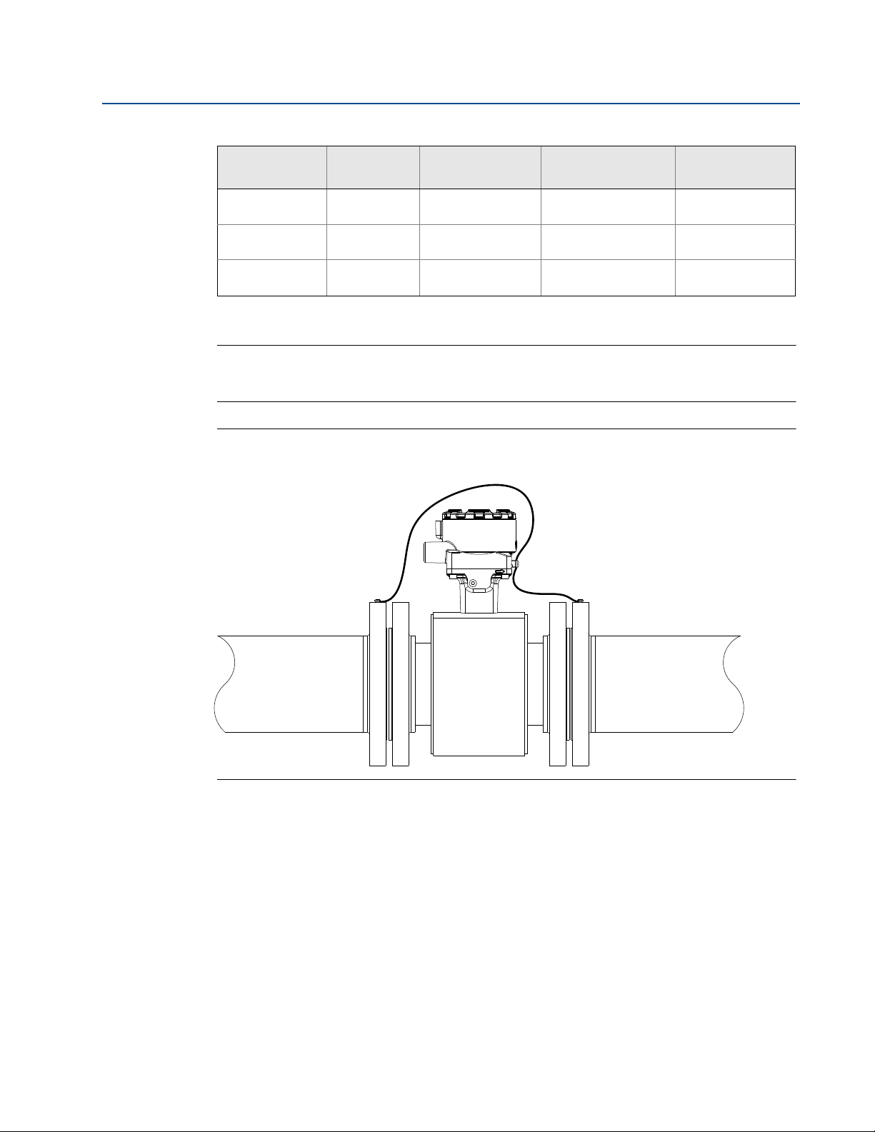
2.11 Process reference connection
Figure 2-10 through Figure 2-13 illustrate process reference connections only. Earth safety
ground is also required as part of the installation but is not shown in the figures. Follow national,
local, and plant electrical codes for safety ground.
Use Ta b l e 2- 1 0 to determine which process reference option to follow for proper installation.
Installation
19
Section 2: Installation
August 2015
Table 2-10. Process Reference Installation Options
Non-Conductive
1. Grounding ring, reference electrode, and lining protectors are not required for process reference. Grounding straps per Figure 2-10
Note
For line sizes 10-in. and larger, the ground strap may come attached to the sensor body near the
flange. See Figure 2-14.
Figure 2-10. Grounding Straps in Conductive Unlined Pipe or Reference Electrode in Lined
Pipe
Type of pipe
Conductive
Unlined Pipe
Conductive
Lined Pipe
Pipe
are sufficient.
Grounding
straps
See Figure 2-10 See Figure 2-11
Insufficient
Grounding
Insufficient
Grounding
Grounding rings
See Figure 2-11
See Figure 2-12
(1)
See Figure 2-13
See Figure 2-10
Not Recommended
Reference
electrode
Reference Manual
00809-0100-4444, Rev AD
Lining
protectors
(1)
See Figure 2-13
See Figure 2-11
See Figure 2-12
(1)
20
Installation
Reference Manual
00809-0100-4444, Rev AD
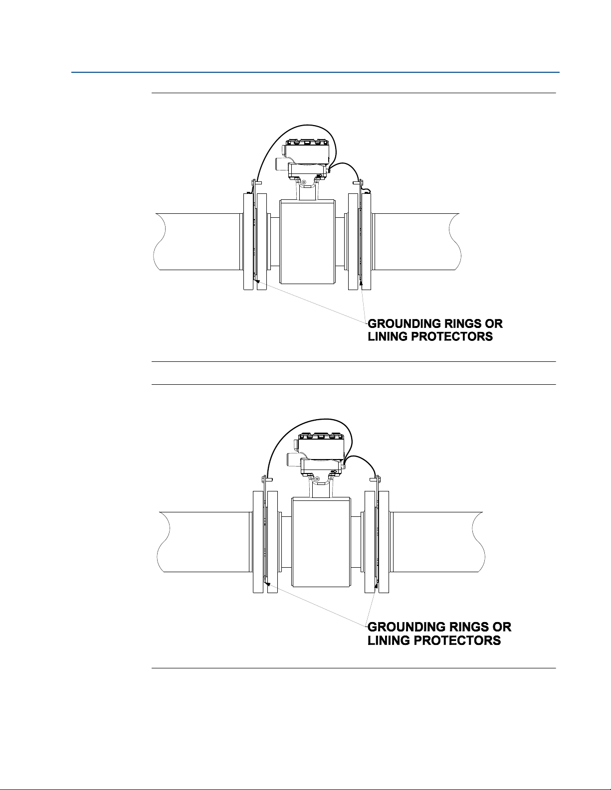
Figure 2-11. Grounding with Grounding Rings or Lining Protectors in Conductive Pipe
Section 2: Installation
August 2015
Figure 2-12. Grounding with Grounding Rings or Lining Protectors in Non-conductive Pipe
Installation
21
Section 2: Installation
August 2015
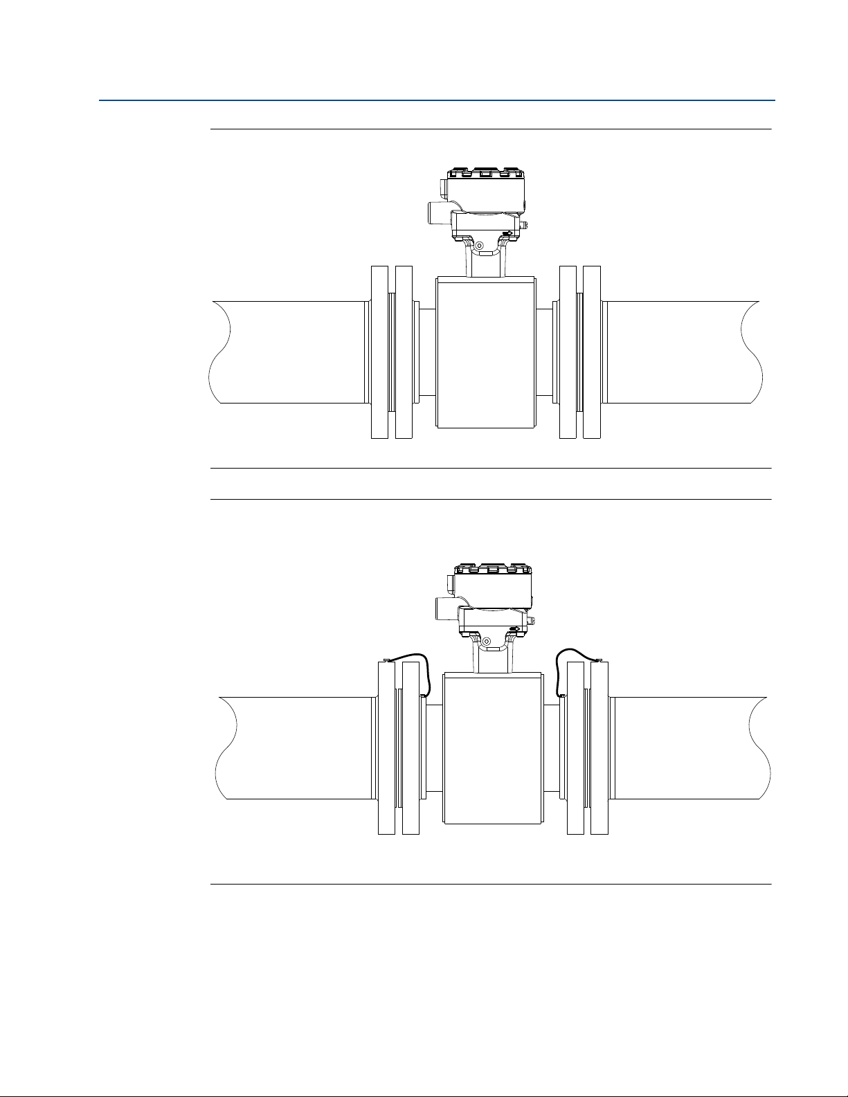
Figure 2-13. Grounding with Reference Electrode in Conductive Unlined Pipe
Reference Manual
00809-0100-4444, Rev AD
Figure 2-14. Grounding for Line Sizes 10-in. and Larger
22
Installation

Reference Manual
00809-0100-4444, Rev AD
2.12 Wiring the transmitter
This wiring section covers the wiring between the transmitter and sensor, the 4-20mA output,
and supplying power to the transmitter. Follow the conduit, cable, and electrical disconnect
requirements in the sections below.
For sensor wiring diagrams, reference Electrical Drawing 08732-1504 in Appendix C Wiring
Diagrams.
For hazardous locations, reference Installation Drawings 08732-2060 and 08732-2062 in
AppendixB .
For information on connecting to another manufacturer’s sensor, refer to Appendix D
Implementing a Universal Transmitter.
2.12.1 Conduit entries and connections
The standard conduit entries for the transmitter and sensor are 1/2 -in. NPT. Thread adapters are
provided for units ordered with M20 conduit entries. Conduit connections should be made in
accordance with national, local, and plant electrical codes. Unused conduit entries should be
sealed with the appropriate certified plugs. The flow sensor is rated IP68 to a depth of 33 feet
(10 meters) for 48 hours. For sensor installations requiring IP68 protection, the cable grands,
conduit, and conduit plugs must be rated for IP68. The plastic shipping plugs do not provide
ingress protection.
Section 2: Installation
August 2015
2.12.2 Conduit requirements
For installations with an intrinsically safe electrode circuit, a separate conduit for the
coil cable and the electrode cable may be required. Refer to the Installation Drawings in
AppendixB.
For installations with non-intrinsically safe electrode circuit, or when using the
combination cable, a single dedicated conduit run for the coil drive and electrode cable
between the sensor and the remote transmitter may be acceptable. Bundled cables
from other equipment in a single conduit are likely to create interference and noise in
the system. See Figure 2-15.
Electrode cables should not be run together and should not be in the same cable tray
with power cables.
Output cables should not be run together with power cables.
Select conduit size appropriate to feed cables through to the flowmeter.
Installation
23
Section 2: Installation
A
B
B
C
D
August 2015
Figure 2-15. Best Practice Conduit Preparation
A. Power
B. Output
C. Coil
D. Elec trode
Reference Manual
00809-0100-4444, Rev AD
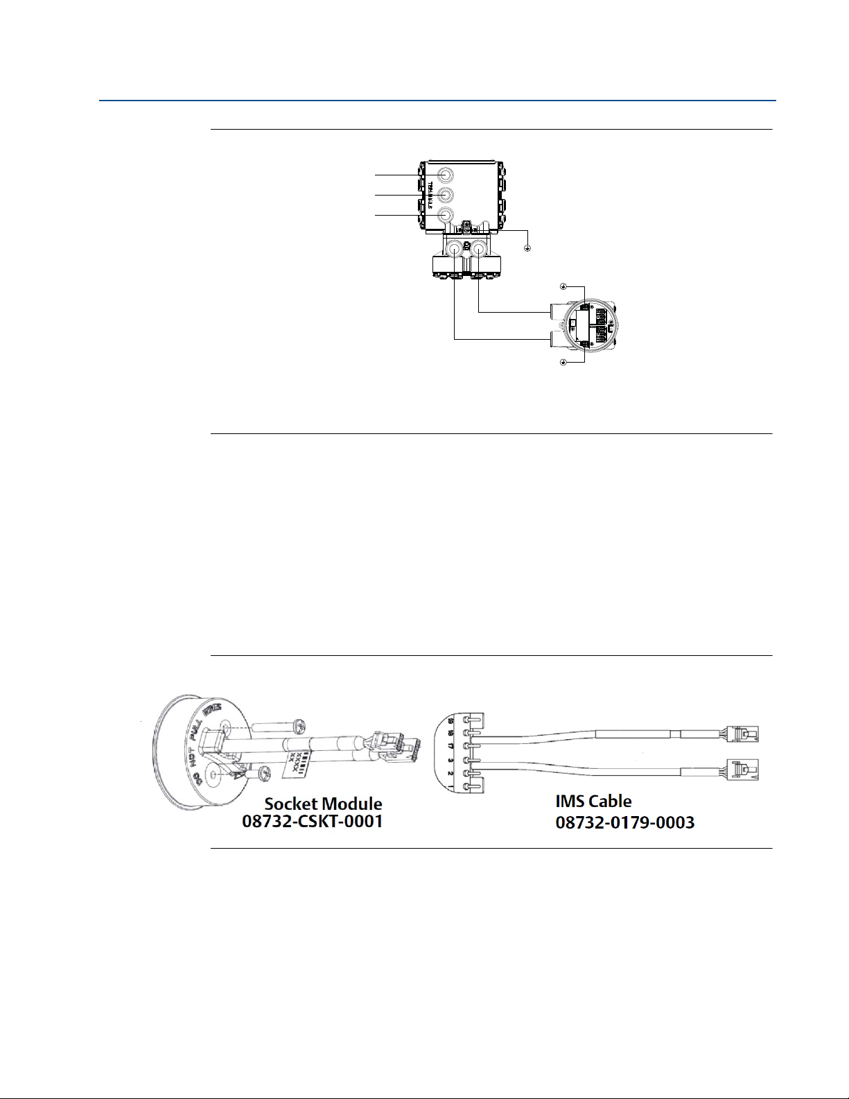
2.12.3 Connecting sensor to transmitter
Integral mount transmitters
Integral mount transmitters ordered with a sensor will be shipped assembled and wired at the
factory using an interconnecting cable (see Figure 2-16). Use only the socket module or IMS
cable provided by Emerson
For replacement transmitters use the existing interconnecting cable from the original assembly.
Replacement cables are available.
Figure 2-16. Interconnecting Cables
™
Process Management.
Remote mount transmitters
24
Cables kits are available as individual component cables or as a combination coil/electrode
cable. Remote cables can be ordered direct from Emerson Process Management using the kit
numbers shown in Tab l e 2 - 11 . Equivalent Alpha cable part numbers are also provided as an
alternative. To order cable, specify length as quantity desired. Equal length of component
cables is required.
Example: 25 feet = Qty (25) 08732-0065-0001
Installation

Reference Manual
00809-0100-4444, Rev AD
Table 2-11. Component Cable Kits
Section 2: Installation
August 2015
Standard temperature (-20 °C to 75 °C)
Cable kit # Description Individual cables Alpha
08732-0065-0001
(feet)
08732-0065-0002
(meters)
08732-0065-0003
(feet)
08732-0065-0004
(meters)
Kit, Component Cables, Std Temp
(includes Coil and Electrode)
Kit, Component Cables, Std Temp
(includes Coil and Electrode)
Kit, Component Cables, Std Temp
(includes Coil and I.S.Electrode)
Kit, Component Cables, Std Temp
(includes Coil and I.S.Electrode)
Coil
Electrode
Coil
Electrode
Coil
Intrinsically Safe Blue Electrode
Coil
Intrinsically Safe Blue Electrode
p/n
518243
518245
518243
518245
518243
518244
518243
518244
Extended temperature (-50 °C to 125 °C)
Cable kit # Description Individual cables Alpha
08732-0065-1001
(feet)
08732-0065-1002
(meters)
08732-0065-1003
(feet)
08732-0065-1004
(meters)
Kit, Component Cables, Ext Temp.
(includes Coil and Electrode)
Kit, Component Cables, Ext Temp.
(includes Coil and Electrode)
Kit, Component Cables, Ext Temp.
(includes Coil and I.S.Electrode)
Kit, Component Cables, Ext Temp.
(includes Coil and I.S.Electrode)
Coil
Electrode
Coil
Electrode
Coil
Intrinsically Safe Blue Electrode
Coil
Intrinsically Safe Blue Electrode
p/n
840310
518189
840310
518189
840310
840309
840310
840309
Table 2-12. Combination Cable kits
Coil/electrode cable (-20 °C to 80 °C)
Cable kit # Description
08732-0065-2001
(feet)
08732-0065-2002
(meters)
08732-0065-3001
(feet)
08732-0065-3002
(meters)
Kit, Combination Cable,
Standard
Kit, Combination Cable,
Submersible
(80°C dry/60°C Wet)
(33ft continuous)
Installation
25
Section 2: Installation
August 2015
Cable requirements
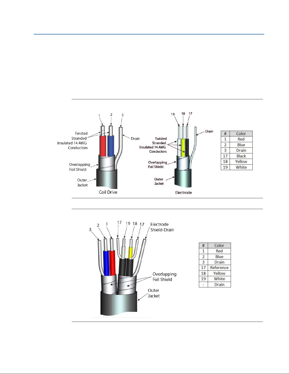
Shielded twisted pairs or triads must be used. For installations using the individual coil drive and
electrode cable, see Figure 2-17. Cable lengths should be limited to less than 500 feet (152 m).
Consult factory for length between 500–1000 feet (152–304 m). Equal length cable is required
for each.
For installations using the combination coil drive/electrode cable, see Figure 2-18. Combination
cable lengths should be limited to less than 330 feet (100 m).
Figure 2-17. Individual Component Cables
Reference Manual
00809-0100-4444, Rev AD
Figure 2-18. Combination Coil / Electrode Cable
26
Installation

Reference Manual
00809-0100-4444, Rev AD
Cable preparation
When preparing all wire connections, remove only the insulation required to fit the wire
completely under the terminal connection. Prepare the ends of the coil drive and electrode
cables as shown in Figure 2-19. Limit the unshielded wire length to less than one inch on both
the coil drive and electrode cables. Any length of unsheathed conductor should be insulated.
Excessive removal of insulation may result in an unwanted electrical short to the transmitter
housing or other wire connections. Excessive unshielded lead length, or failure to connect cable
shields properly, may expose the unit to electrical noise, resulting in an unstable meter reading.
Figure 2-19. Cable Ends
Section 2: Installation
August 2015
Installation
Shock Hazard
Potential shock hazard across remote junction box terminals 1 & 2 (40V).
Explosion Hazard
Electrodes exposed to process. Use only compatible transmitter and approved installation
practices.
For process temperatures greater than 284 °F (140 °C), use a wire rated for 257 °F (125 °C).
27

Section 2: Installation
Sensor Tra ns mit er
August 2015
Figure 2-20. Remote Junction Box Views
Wire Ter mi na l Wire Te rm in al
RED 1 RED 1
BLUE 2 BLUE 2
BLACK 17 Shield 3
YELLOW 18 BLACK 17
WHITE 19 YELLOW 18
Reference Manual
00809-0100-4444, Rev AD
WHITE 19
For sensor wiring diagrams, reference the installation drawings in Appendix C Wiring Diagrams.
For hazardous locations, reference the drawings in Appendix B Product Certifications.
2.12.4 8732EM terminal block connections
Remove the back cover of the transmitter to access the terminal block. See Figure 2-21 for
terminal identification. To connect pulse output and/or discrete input/output, reference
Appendix C Wiring Diagrams. For installations with intrinsically safe outputs, reference the
hazardous location installation drawings in Appendix B Product Certifications.
Figure 2-21. Terminal Block Connections
28
Installation

Reference Manual
- 4-20mA
+ 4-20mA
00809-0100-4444, Rev AD
2.12.5 Analog output
The analog output signal is a 4-20mA current loop. The loop can be powered internally or
externally via a hardware switch located on the front of the electronics stack. The switch is set to
internal power when shipped from the factory. For units with a display, the LOI must be removed
to change switch position.
Intrinsically safe analog output requires a shielded twisted pair cable.
For HART communication a minimum loop resistance of 250 ohms is required. It is
recommended to use individually shielded twisted pair cable. The minimum conductor size is
0.51 mm diameter (#24 AWG) for cable runs less than 5,000 feet (1,500m) and 0.81 mm
diameter (#20 AWG) for longer distances.
Internal power
The 4-20mA analog signal is a 24VDC active output.
Maximum allowable loop resistance is 500 ohms.
Section 2: Installation
August 2015
Wire terminal 1 (+) and terminal 2 (-). See Figure 2-22.
Figure 2-22. Analog Wiring—Internal Power
Note
Terminal polarity for the analog output is reversed between internally and externally powered.
Installation
29

Section 2: Installation
+ POWER
- SUPPLY
Power Supply (Volts)
Load (Ohms)
Operating
Regio n
600
0
10.8 30
August 2015
External power
The 4-20mA analog signal is passive and must be powered from an external power source.
Power at the transmitter terminals must be 10.8 - 30VDC.
Wire terminal 1 (-) and terminal 2 (+). See Figure 2-23.
Figure 2-23. Analog Wiring—External Power
Reference Manual
00809-0100-4444, Rev AD
30
Analog loop load limitations
Maximum loop resistance is determined by the voltage level of the external power supply, as
described in Figure 2-24.
Figure 2-24. Analog Loop Load Limitations
R
= 31.25 (Vps – 10.8)
max
V
= Power Supply Voltage (Volts)
ps
R
= Maximum Loop Resistance (Ohms)
max
Installation

Reference Manual
0.2
0.3
0.4
0.5
0.6
0.7
0.8
0.9
1.0
1.1
1.2
12 16 20 24 28 32 36 40
Supply Current (DC Amps)
Power Supply (DC Volts)
0.12
0.14
0.16
0.18
0.20
0.22
0.24
90 110 130 150 170 190 210 230 250
Supply Current (Amps)
Power Supply (VAC)
AC Supply Characteristics
00809-0100-4444, Rev AD
2.12.6 Powering the transmitter
The 8732EM transmitter is available in two models. The AC powered transmitter is designed to
be powered by 90–250VAC (50/60Hz). The DC powered transmitter is designed to be powered
by 12–42VDC. Before connecting power to the 8732EM, be sure to have the proper power
supply, conduit, and other accessories. Wire the transmitter according to national, local, and
plant electrical requirements for the supply voltage. See
Figure 2-25. DC Power Requirements
Section 2: Installation
August 2015
Figure 2-25 or Figure 2-26.
Peak inrush is 42A at 42VDC supply, lasting approximately 1ms.
Inrush for other supply voltages can be estimated with:
Inrush (Amps) = Supply (Volts) / 1.0
Figure 2-26. AC Power Requirements
Installation
31

Section 2: Installation
20
22
24
26
28
30
32
34
90 110 130 150 170 190 210 230 250
Apparent Power (VA)
Power Supply (VAC)
Apparent Power (VA)
August 2015
Peak inrush is 35.7A at 250VAC supply, lasting approximately 1ms.
Inrush for other supply voltages can be estimated with:
Reference Manual
00809-0100-4444, Rev AD
Inrush (Amps) = Supply (Volts) / 7.0
Supply wire requirements
Use 10–18 AWG wire rated for the proper temperature of the application. For wire 10–14 AWG
use lugs or other appropriate connectors. For connections in ambient temperatures above
122 °F (50 °C), use a wire rated for 194 °F (90 °C). For DC powered transmitters with extended
cable lengths, verify that there is a minimum of 12VDC at the terminals of the transmitter with
the device under load.
Electrical disconnect requirements
Connect the device through an external disconnect or circuit breaker per national and local
electrical code.
Installation category
The installation category for the 8732EM is OVERVOLTAGE CAT II.
32
Installation

Reference Manual
00809-0100-4444, Rev AD
Overcurrent protection
The 8732EM transmitter requires overcurrent protection of the supply lines. Fuse rating and
compatible fuses are shown in Tab le 2-13.
Table 2-13. Fuse Requirements
Input
voltage
Section 2: Installation
August 2015
Fuse rating Compatible fuse
90–250VAC
rms
12–42VDC 3 Amp, 250V, I2t ≥ 14 A2s
1 Amp, 250V, I2t ≥ 1.5 A2s
Rating, Fast Acting
Rating, Fast Acting
Power terminals
See Figure 2-21 for terminal block connections.
For AC powered transmitter (90–250VAC, 50/60 Hz):
Connect AC Neutral to terminal 9 (AC N/L2) and AC Line to terminal 10 (AC/L1).
For DC powered transmitter:
Connect negative to terminal 9 (DC -) and positive to terminal 10 (DC +).
DC powered units may draw up to 1.2A.
2.13 Cover jam screw
For flow meters shipped with a cover jam screw, the screw should be installed after the
instrument has been wired and powered up. Follow these steps to install the cover jam screw:
1. Verify the cover jam screw is completely threaded into the housing.
Bussman AGC-1, Littelfuse 31201.5HXP
Bel Fuse 3AG 3-R, Littelfuse 312003P, Schurter 0034.5135
Installation
2. Install the housing cover and verify the cover is tight against the housing.
3. Using a 2.5 mm hex wrench, loosen the jam screw until it contacts the transmitter
cover.
4. Turn the jam screw an additional
1
/2 turn counterclockwise to secure the cover.
Note
Application of excessive torque may strip the threads.
5. Verify the cover cannot be removed.
33

Section 2: Installation
August 2015
2.14 Basic configuration
Once the magnetic flowmeter is installed and power has been supplied, the transmitter must be
configured through the basic setup. The basic setup parameters can be configured through
either an LOI or a HART communication device.
For instructions on operation of the LOI or HART Communication device, refer to
Section 4.
If configuration beyond the basic setup parameters is required, refer to Section 5 for a
complete list of device parameters.
Configuration settings are saved in nonvolatile memory within the transmitter.
2.14.1 Basic setup
Tag
Reference Manual
00809-0100-4444, Rev AD
LOI menu path
Traditional Fast Keys
Device dashboard
Basic Setup, Tag
1,3,1
2,2,9,1,1
Tag is the quickest and shortest way of identifying and distinguishing between transmitters.
Transmitters can be tagged according to the requirements of your application. The tag may be
up to eight characters long.
Flow units (PV)
LOI menu path
Traditional Fast Keys
Device dashboard
The flow units variable specifies the format in which the flow rate will be displayed. Units should
be selected to meet your particular metering needs. See Ta b l e 2 -1 4 for available units of
measure.
Basic Setup, Flow Units, PV Units
1,3,1
2,2,1,2
Line size
LOI menu path
Traditional Fast Keys
Device dashboard
The line size (sensor size) must be set to match the actual sensor connected to the transmitter.
The size must be specified in inches. See Tab l e 2 -1 5 for available sensor sizes.
Basic Setup, Line Size
1,3,1
2,2,1,4,2
34
Upper Range Value (URV)
LOI menu path
Traditional Fast Keys
Device dashboard
The URV sets the 20 mA point for the analog output. This value is typically set to full-scale flow.
The units that appear will be the same as those selected under the flow units parameter. The
URV may be set between –39.3 ft/s to 39.3 ft/s (–12 m/s to 12 m/s). There must be at least 1
ft/s (0.3 m/s) span between the URV and LRV.
Basic Setup, PV URV
1,3,1
2,2,1,3,3
Installation

Reference Manual
00809-0100-4444, Rev AD
Lower Range Value (LRV)
Section 2: Installation
August 2015
LOI menu path
Traditional Fast Keys
Device dashboard
Basic Setup, PV LRV
1,3,1
2,2,1,3,2
The LRV sets the 4 mA point for the analog output. This value is typically set to zero flow. The
units that appear will be the same as those selected under the flow units parameter. The LRV
may be set between –39.3 ft/s to 39.3 ft/s (–12 m/s to 12 m/s). There must be at least 1 ft/s (0.3
m/s) span between the URV and LRV.
Calibration number
LOI menu path
Traditional Fast Keys
Device dashboard
The sensor calibration number is a 16-digit number generated at the Rosemount factory during
flow calibration, is unique to each sensor, and is located on the sensor tag.
Basic Setup, Cal Number
1,3,1
2,2,1,4,1
PV damping
LOI menu path
Traditional Fast Keys
Device dashboard
Primary variable damping allows selection of a response time, in seconds, to a step change in
flow rate. It is most often used to smooth fluctuations in output.
Basic Setup, PV Damping
1,3,1
2,2,1,3,4
Installation
35

Section 2: Installation
August 2015
Table 2-14. Available Flow Units
Volumetric units Mass units
gal / sec lbs / sec
gal / min lbs / min
gal / hr lbs / hr
gal / day lbs / day
L / sec kg / sec
L / min kg / min
L / hr kg / hr
L / day kg / day
ft3 / sec (s) tons / min
ft3 / min (s) tons / hr
ft3 / hr (s) tons / day
ft3 / day (m) tons / min
cm3 / min (m) tons / hr
m3 / sec (m) tons / day
Reference Manual
00809-0100-4444, Rev AD
m3 / min
m3 / hr
m3 / day ft / sec
Impgal / sec m / sec
Impgal / min
Impgal / hr
Impgal / day Special (User Defined)
B42 / sec (1 barrel = 42 gallons)
B42 / min (1 barrel = 42 gallons)
B42 / hr (1 barrel = 42 gallons)
B42 / day (1 barrel = 42 gallons)
B31 / sec (1 barrel = 31 gallons)
B31 / min (1 barrel = 31 gallons)
B31 / hr (1 barrel = 31 gallons)
B31 / day (1 barrel = 31 gallons)
Velocity units
Special units
36
Installation

Reference Manual
00809-0100-4444, Rev AD
Table 2-15. Available Sensor Sizes
Section 2: Installation
August 2015
Sensor size
0.10-in. (2.5 mm) 18-in. (450 mm)
0.15-in. (4 mm) 20-in. (500 mm)
0.25-in. (6 mm) 24-in. (600 mm)
0.30-in. (8 mm) 28-in. (700 mm)
0.50-in. (15 mm) 30-in. (750 mm)
0.75-in. (20 mm) 32-in. (800 mm)
1.0-in. (25 mm) 36-in. (900 mm)
1.5-in. (40 mm) 40-in. (1000 mm)
2.0-in. (50 mm) 42-in. (1050 mm)
2.5-in. (65 mm) 44-in. (1100 mm)
3.0-in. (80 mm) 48-in. (1200 mm)
4.0-in. (100 mm) 54-in. (1350 mm)
5.0-in. (125 mm) 56-in. (1400 mm)
6.0-in. (150 mm) 60-in. (1500 mm)
8.0-in. (200 mm) 64-in. (1600 mm)
10-in. (250 mm) 66-in. (1650 mm)
12-in. (300 mm) 72-in. (1800 mm)
14-in. (350 mm) 78-in. (1950 mm)
16-in. (400 mm) 80-in. (2000 mm)
Installation
37

Section 2: Installation
August 2015
Reference Manual
00809-0100-4444, Rev AD
38
Installation

Reference Manual
00809-0100-4444, Rev AD
Section 3: Advanced Installation Details
August 2015
Section 3 Advanced Installation Details
Introduction . . . . . . . . . . . . . . . . . . . . . . . . . . . . . . . . . . . . . . . . . . . . . . . . . . . . . . . . . . . . . . . page 39
Hardware switches . . . . . . . . . . . . . . . . . . . . . . . . . . . . . . . . . . . . . . . . . . . . . . . . . . . . . . . . . . page 39
Hardware switches . . . . . . . . . . . . . . . . . . . . . . . . . . . . . . . . . . . . . . . . . . . . . . . . . . . . . . . . . . page 39
Additional loops . . . . . . . . . . . . . . . . . . . . . . . . . . . . . . . . . . . . . . . . . . . . . . . . . . . . . . . . . . . . page 41
Connect discrete input . . . . . . . . . . . . . . . . . . . . . . . . . . . . . . . . . . . . . . . . . . . . . . . . . . . . . . page 49
Process reference connection . . . . . . . . . . . . . . . . . . . . . . . . . . . . . . . . . . . . . . . . . . . . . . . . page 50
Coil housing configuration . . . . . . . . . . . . . . . . . . . . . . . . . . . . . . . . . . . . . . . . . . . . . . . . . . . page 50
3.1 Introduction
This section details some of the advanced installation considerations when utilizing the
Rosemount
®
8700M Magnetic Flowmeter Platform.
3.2 Safety messages
The electronics may store energy after power is removed. Allow ten minutes for charge to
dissipate prior to removing electronics compartment cover.
Note
The electronics stack is electrostatically sensitive. Be sure to observe handling precautions for
static-sensitive components.
3.3 Hardware switches
The electronics are equipped with four user-selectable hardware switches. These switches set
the Alarm Mode, Internal/External Analog Power, Transmitter Security, and Internal/External
Pulse Power.
Definitions of these switches and their functions are provided below. To change the settings, see
below.
3.3.1 Alarm mode
If an event occurs that would trigger an alarm in the electronics, the analog output will be driven
high or low, depending on the switch position. The switch is set in the HIGH position when
shipped from the factory. Refer to Table 5-1 on page 88 and Table 5-2 on page 88 for analog
output values of the alarm.
Advanced Installation Details
39

Section 3: Advanced Installation Details
August 2015
3.3.2 Transmitter security
The security switch on the 8732EM allows the user to lock out any configuration changes
attempted on the transmitter. No changes to the configuration are allowed when the switch is
in the ON position. The flow rate indication and totalizer functions remain active at all times.
With the switch in the ON position, access to review the operating parameters is available. No
configuration changes are allowed.
Transmitter security is set in the OFF position when shipped from the factory.
3.3.3 Internal/external analog power
The 8732EM 4-20 mA loop may be powered internally or by an external power supply. The
internal /external power supply switch determines the source of the 4-20 mA loop power.
Transmitters are shipped from the factory with the switch set in the INTERNAL position.
The external power option is required for multidrop configurations. A 10-30 VDC external
supply is required and the 4-20 mA power switch must be set to the EXTERNAL position. For
further information on 4-20 mA external power, see “Analog output” on page 29.
Reference Manual
00809-0100-4444, Rev AD
3.3.4 Internal/external pulse power
The 8732EM pulse loop may be powered internally or by an external power supply. The internal/external power supply switch determines the source of the pulse loop power.
Transmitters are shipped from the factory with the switch set in the EXTERNAL position.
A 5-28 VDC external supply is required when the pulse power switch is set to the EXTERNAL
position. For further information on the pulse external power, see “Connect pulse output” on
page 41.
3.3.5 Changing hardware switch settings
To change the switch settings, complete the steps below:
Note
The hardware switches are located on the top side of the electronics board and changing their
settings requires opening the electronics housing. If possible, carry out these procedures away
from the plant environment in order to protect the electronics.
1. Place the control loop into manual control.
2. Disconnect power to the transmitter
40
3. Remove the electronics compartment cover. If the cover has a cover jam screw, this
must be loosened prior to removal of the cover.
4. Remove the LOI, if applicable.
5. Identify the location of each switch (see Figure 3-1).
Advanced Installation Details
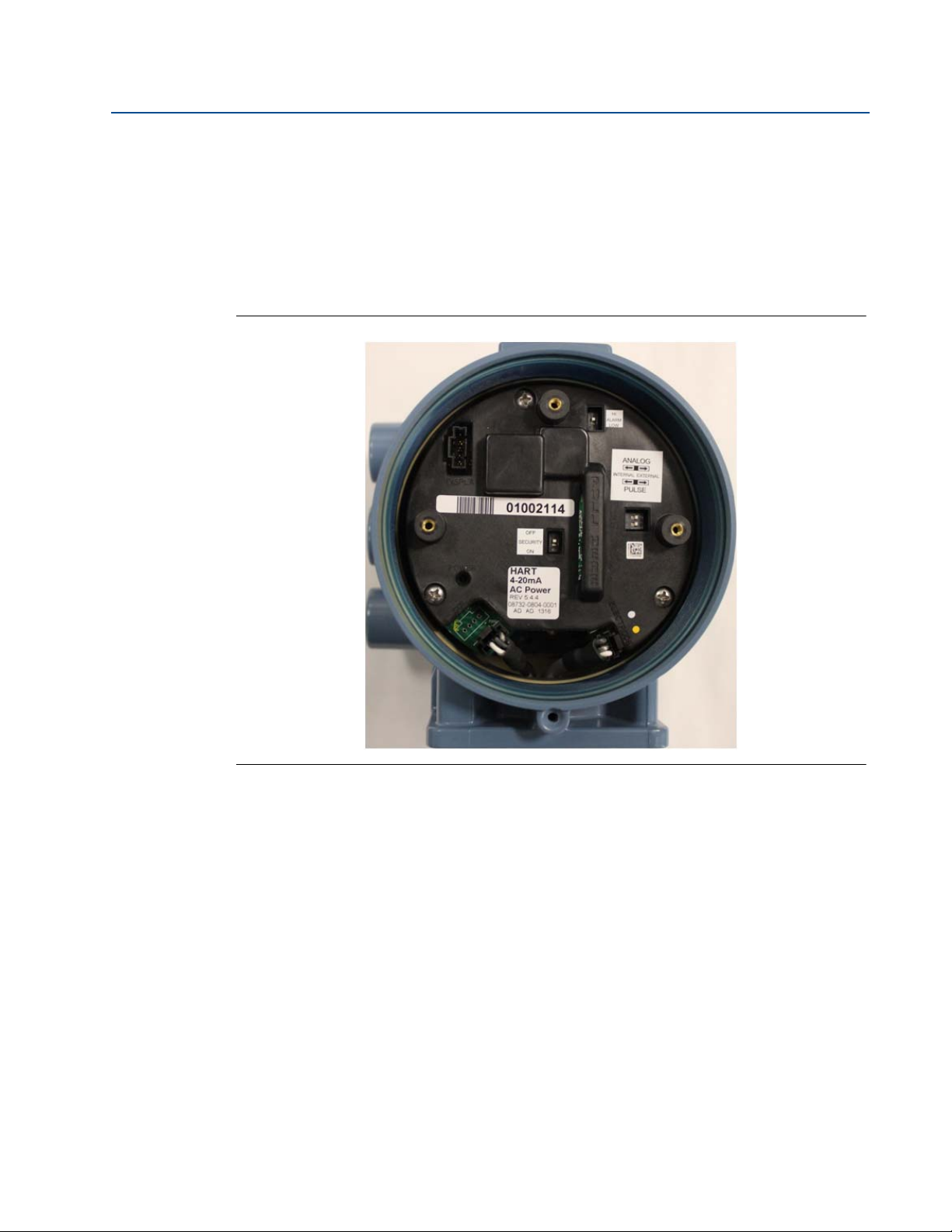
Reference Manual
00809-0100-4444, Rev AD
6. Change the setting of the desired switches with a small, non-metallic tool.
7. Replace the LOI if applicable, and the electronics compartment cover. If the cover has a
8. Return power to the transmitter and verify the flow measurement is correct.
9. Return the control loop to automatic control.
Figure 3-1. Rosemount 8732EM Electronics Stack and Hardware Switches
Section 3: Advanced Installation Details
August 2015
cover jam screw, this must be tightened to comply with installation requirements. See
“Cover jam screw” on page 33 for details on the cover jam screw.
3.4 Additional loops
There are three additional loop connections available on the 8732EM Transmitter:
Pulse output - used for external or remote totalization.
Channel 1 can be configured as discrete input or discrete output.
Channel 2 can be configured as discrete output only.
3.4.1 Connect pulse output
The pulse output function provides a galvanically isolated frequency signal that is proportional
to the flow through the sensor. The signal is typically used in conjunction with an external
totalizer or control system. The default position of the internal/external pulse power switch is in
the EXTERNAL position. The user-selectable power switch is located on the electronics board.
Advanced Installation Details
41

Section 3: Advanced Installation Details
August 2015
External
For transmitters with the internal/external pulse power switch (output option code A) set in the
EXTERNAL position or transmitters with intrinsically safe outputs (output option code B) the
following requirements apply:
Supply voltage: 5 to 28 VDC
Maximum current: 100 mA
Maximum power: 1.0 W
Load resistance: 200 to 10k Ohms (typical value 1k Ohms)
Output option
code
A 5-28 VDC See Figure 3-2 on page 43
B 5 VDC See Figure 3-3 on page 43
B 12 VDC See Figure 3-4 on page 44
B 24 VDC See Figure 3-5 on page 44
Reference Manual
00809-0100-4444, Rev AD
Supply voltage Resistance vs cable length
Pulse mode: Fixed pulse width or 50% duty cycle
Pulse duration: 0.1 to 650 ms (adjustable)
Maximum pulse frequency: Output option code A is 10,000 Hz
Maximum pulse frequency: Output option code B is 5000 Hz
FET switch closure: solid state switch
42
Advanced Installation Details
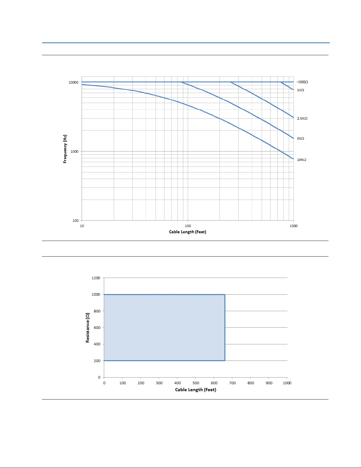
Reference Manual
00809-0100-4444, Rev AD
Section 3: Advanced Installation Details
Figure 3-2. Output Option Code A—Maximum Frequency vs. Cable Length
August 2015
Figure 3-3. Output Option Code B—5 VDC Supply
At 5000 Hz operation with a 5 VDC supply, pull-up resistances of 200 to 1000 Ohms allow
cable lengths up to 660 ft (200 m).
Advanced Installation Details
43

Section 3: Advanced Installation Details
August 2015
Figure 3-4. Output Option Code B—2 VDC Supply
Reference Manual
00809-0100-4444, Rev AD
At 5000 Hz operation with a 12 VDC supply, pull-up resistances of 500 to 2500 Ohms allow
cable lengths up to 660 ft (200 m). Resistances from 500 to 1000 Ohms allow a cable
length of 1000 ft (330 m).
Figure 3-5. Output Option Code B—24 VDC Supply
44
At 5000 Hz operation with a 24 VDC supply, pull-up resistances of 1000 to 10,000 Ohms
allow cable lengths up to 660 ft (200 m). Resistances from 1000 to 2500 Ohms allow a
cable length of 1000 ft (330 m).
Advanced Installation Details

Reference Manual
Electro-mechanical
Counter
Schematic showing
FET between
terminal 3 and 4
5-24 V DC
Power Supply
00809-0100-4444, Rev AD
Complete the following steps to connect an external power supply.
1. Ensure the power source and connecting cable meet the requirements outlined
2. Turn off the transmitter and pulse output power sources.
3. Run the power cable to the transmitter.
4. Connect - DC to terminal 3.
5. Connect + DC to terminal 4.
Refer to Figure 3-6 and Figure 3-7.
Figure 3-6. Connecting an Electromechanical Totalizer/Counter with External Power
Section 3: Advanced Installation Details
August 2015
previously.
Supply
Note
Total loop impedance must be sufficient to keep loop current below maximum rating. A resistor
can be added in the loop to raise impedance.
Advanced Installation Details
45

Section 3: Advanced Installation Details
August 2015
Figure 3-7. Connecting to an Electronic Totalizer/Counter with External Power Supply
Schematic showing
FET between
terminal 3 and 4
Electronic
Counter
Reference Manual
00809-0100-4444, Rev AD
5-24 V DC
Power Supply
Note
Total loop impedance must be sufficient to keep loop current below maximum rating.
46
Advanced Installation Details

Reference Manual
Electronic
Counter
Schematic showing
FET between
terminal 3 and 4
00809-0100-4444, Rev AD
Internal
When the pulse switch is set to internal, the pulse loop will be powered from the transmitter.
Supply voltage from the transmitter can be up to 12 VDC. Refer to Figure 3-8 and connect the
transmitter directly to the counter. Internal pulse power can only be used with an electronic
totalizer or counter and cannot be used with an electromechanical counter.
1. Turn off the transmitter.
2. Connect - DC to terminal 3.
3. Connect + DC to terminal 4.
Figure 3-8. Connecting to an Electronic Totalizer / Counter with Internal Power Supply
Section 3: Advanced Installation Details
August 2015
Advanced Installation Details
47

Section 3: Advanced Installation Details
August 2015
3.4.2 Connect discrete output
The discrete output control function can be configured to drive an external signal to indicate
zero flow, reverse flow, empty pipe, diagnostic status, flow limit, or transmitter status. The
following requirements apply:
Supply Voltage: 5 to 28 VDC
Maximum Voltage: 28 VDC at 240 mA
Switch Closure: solid state relay
For discrete output control, connect the power source and control relay to the transmitter. To
connect external power for discrete output control, complete the following steps:
1. Ensure the power source and connecting cable meet the requirements outlined
previously.
2. Turn off the transmitter and discrete power sources.
3. Run the power cable to the transmitter.
4. Channel 1: Connect -DC to terminal 5, connect +DC to terminal 6.
Reference Manual
00809-0100-4444, Rev AD
5. Channel 2: Connect -DC to terminal 7, connect +DC to terminal 8.
Refer to Figure 3-9 and Figure 3.5.
Figure 3-9. Connect Discrete Output to Relay or Control System Input
Control Relay
or Input
5-28 V DC
Power Supply
48
Note
Total loop impedance must be sufficient to keep loop current below maximum rating. A resistor
can be added in the loop to raise impedance.
Advanced Installation Details

Reference Manual
Ω
Relay Contact or Control
System Output
5-28 V DC
Power Supply
00809-0100-4444, Rev AD
3.4.3 Connect discrete input
The discrete input can provide positive zero return (PZR) or net totalizer reset. The following
requirements apply:
Supply Voltage: 5 to 28 VDC
Control Current: 1.5 - 20mA
Input Impedance: 2.5 k plus 1.2V Diode drop. See Figure 3-11.
To connect the discrete input, complete the following steps.
1. Ensure the power source and connecting cable meet the requirements outlined
previously.
2. Turn off the transmitter and discrete power sources.
3. Run the power cable to the transmitter.
4. Connect -DC to terminal 5.
5. Connect +DC to terminal 6.
Section 3: Advanced Installation Details
August 2015
Refer to Figure 3-10 and Figure 3-11.
Figure 3-10. Connecting Discrete Input
Advanced Installation Details
49

Section 3: Advanced Installation Details
0
5
10
15
20
25
30
2.5
5
7.5 10
12.5 15
0
Digital Input Operating Range
Supply Voltage
Series Resistance Ωin + Ωext (Kohms)
August 2015
Figure 3-11. Discrete Input Operating Range
Reference Manual
00809-0100-4444, Rev AD
3.5 Process reference connection
Establishing a process reference for the sensor is one of the most important details of sensor
installation. Proper process reference creates the lowest noise environment for the transmitter
to make a stable reading. Refer to Table 2-10 on page 20 to determine which option to follow for
proper installation.
Note
Consult factory for installations requiring cathodic protection or situations where there are high
electrical currents or high electrical potentials present in the process.
3.6 Coil housing configuration
The coil housing provides physical protection of the coils and other internal components from
contamination and physical damage that might occur in an industrial environment. The coil
housing is an all-welded and gasket-free design.
The 8705 model is available in four coil housing configurations. Configurations are identified by
the M0, M1, M2, or M4 options codes found in the model number. The 8711 and 8721 models
are only available in one coil housing coil configuration; a separate option code is not available.
50
Advanced Installation Details
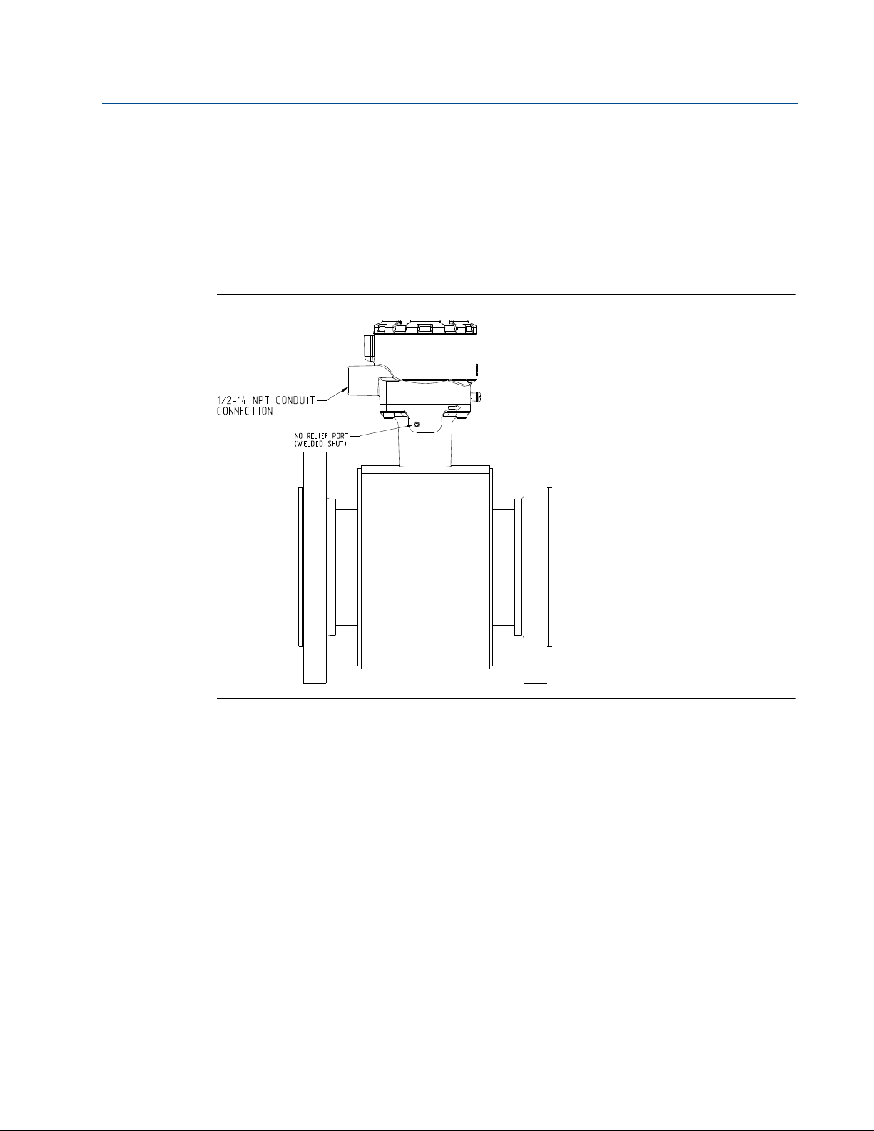
Reference Manual
00809-0100-4444, Rev AD
Section 3: Advanced Installation Details
3.6.1 Standard coil housing configuration
The standard coil housing configuration is a factory sealed all-welded enclosure and is available
for the following models (see Figure 3-12):
8705 with option code M0 - 8705xxxxxxxxM0
8711 with option code M/L - 8711xxxxxxM/L
8721 with option code R/U - 8721xxxxxxR/U
Figure 3-12. Standard Housing Configuration (8705 Shown)
August 2015
Advanced Installation Details
51
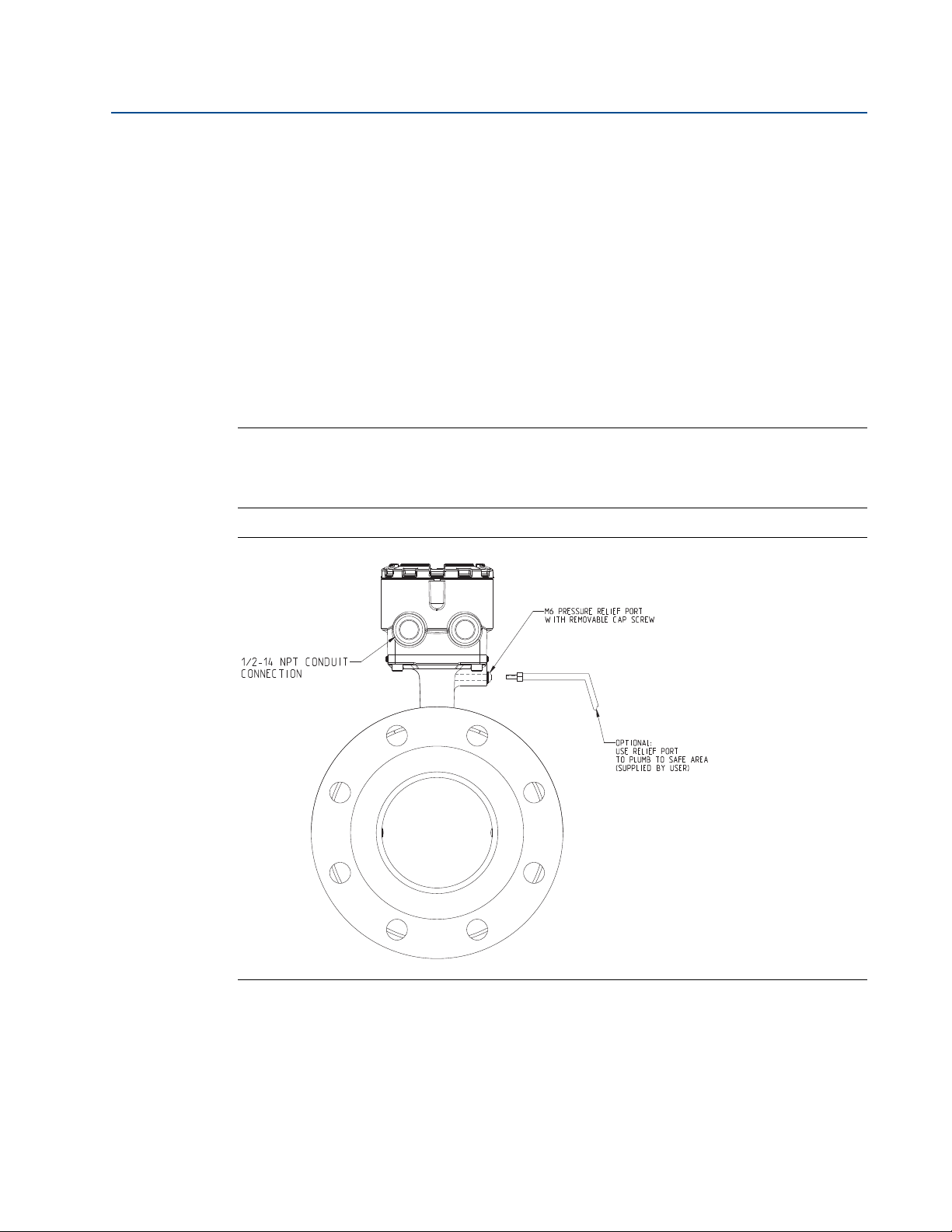
Section 3: Advanced Installation Details
August 2015
3.6.2 Process leak protection (option M1)
The 8705 is available with process leak detection through the use of a threaded connection and
pressure relief valve (PRV). This coil housing configuration is a factory sealed all-welded
enclosure. The M1 configuration is available for the 8705 only.
8705 with option code M1 - 8705xxxxxxxxM1
A PRV can be installed in the threaded connection to prevent possible over-pressuring of the coil
housing caused by a primary seal failure. The PRV is capable of venting fugitive emissions when
pressure inside the coil housing exceeds five psi. Additional piping may be connected to the PRV
to drain any process leakage to a safe location (see Figure 3-13).
In the event of a primary seal failure, this configuration will not protect the coils or other internal
components of the sensor from exposure to the process fluid.
Note
The PRV is supplied with the meter to be installed by the customer. Installation of the PRV and
any associated piping must be performed in accordance with environmental and hazardous area
requirements.
Reference Manual
00809-0100-4444, Rev AD
Figure 3-13. 8705 with M1 Coil Housing Configuration and PRV
52
Advanced Installation Details
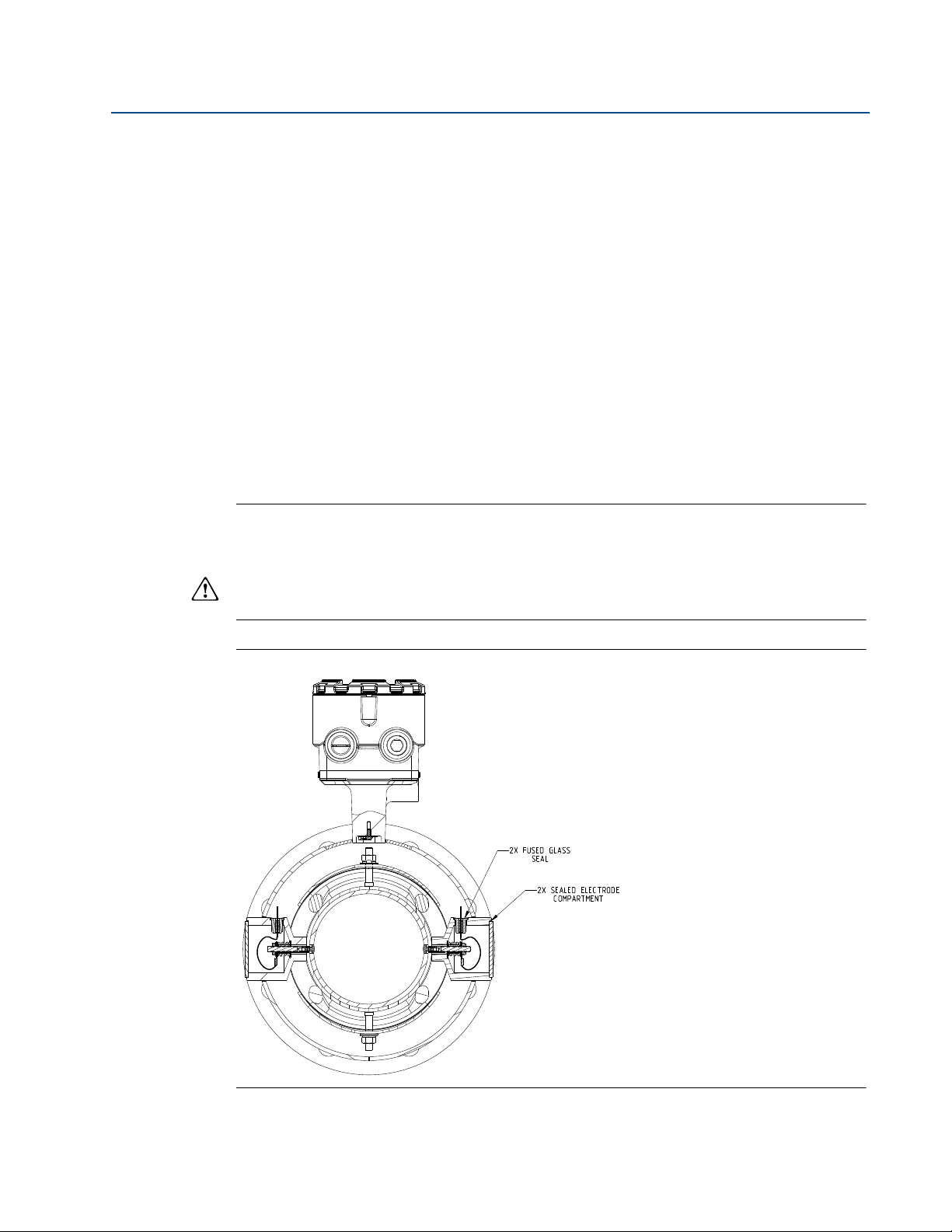
Reference Manual
00809-0100-4444, Rev AD
Section 3: Advanced Installation Details
3.6.3 Process leak containment (Option M2 or M4)
The 8705 is available with process leak containment. The coil housing configuration is a factory
sealed all-welded enclosure with the addition of sealed electrode compartments. The M2/M4
configuration is available for the 8705 only.
8705 with option code M2/M4 - 8705xxxxxxxxM2/M4
This configuration divides the coil housing into separate compartments, one for each electrode
and one for the coils. In the event of a primary seal failure, the fluid is contained in the electrode
compartment. The sealed electrode compartment prevents the process fluid from entering the
coil compartment where it may damage the coils and other internal components. The electrode
compartments are designed to contain the process fluid up to a maximum pressure of 740 psig.
Code M2 - sealed, welded coil housing with separate sealed and welded electrode
compartments (see Figure 3-14).
Code M4 - sealed, welded coil housing with separate sealed and welded electrode
compartments with a threaded port on the electrode tunnel cap, capable of venting
fugitive emissions (see Figure 3-15).
August 2015
Note
To properly vent process fluid from the electrode compartment to a safe location, additional
piping is required and must be installed by the user. Installation of any associated piping must be
performed in accordance with environmental and hazardous area requirements. In the event of
primary seal failure, the electrode compartment may be pressurized. Use caution when
removing the cap screw.
Figure 3-14. 8705 with M2 Coil Housing Configuration
Advanced Installation Details
53
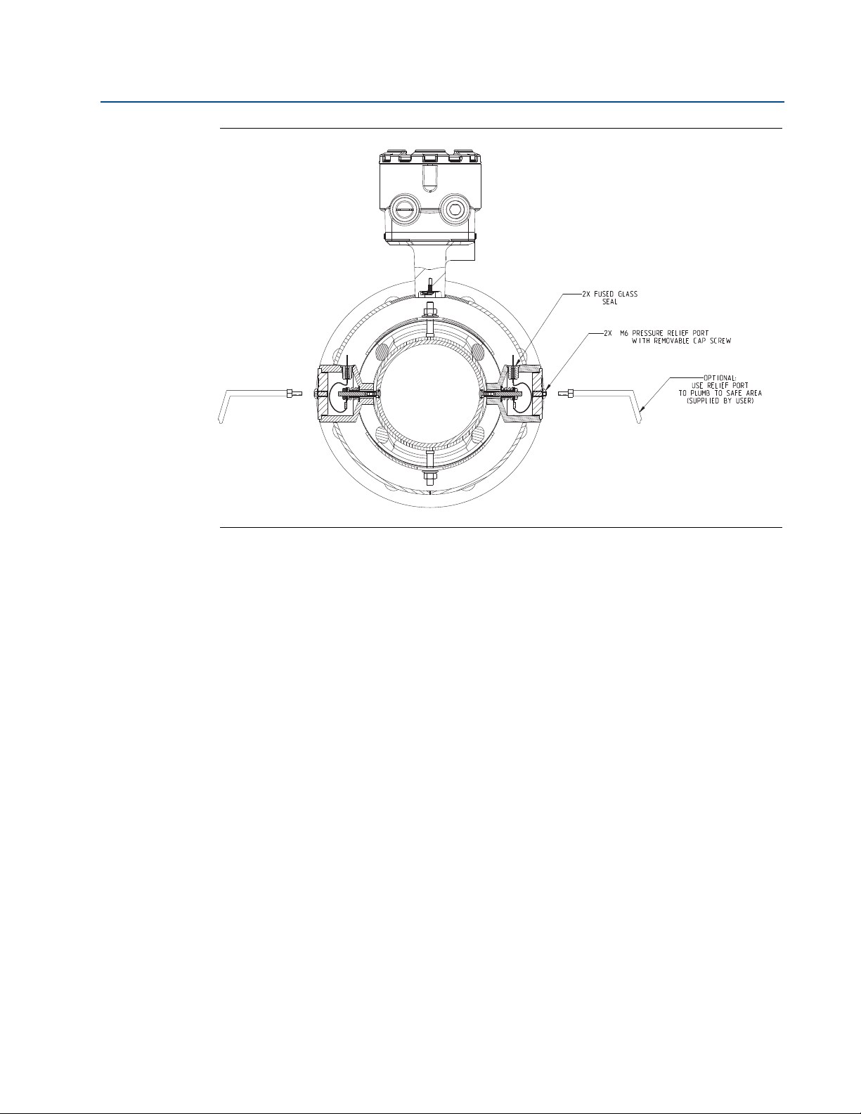
Section 3: Advanced Installation Details
August 2015
Figure 3-15. 8705 with M4 Coil Housing Configuration
Reference Manual
00809-0100-4444, Rev AD
3.6.4 Higher temperature applications and sensor insulation
best practices
Insulation of the magnetic flowmeter sensor is not typically recommended. However, in
applications with higher temperature process fluids (above 150°F / 65°C), plant safety, sensor
reliability, and sensor longevity can be improved with careful attention to proper insulation.
1. In applications where process fluid permeation of the liner has been observed or may
be expected, the rate of permeation can be reduced by decreasing the temperature
gradient between the process fluid and the outside of the meter body. In these
applications only the space between the process flanges and the coil housing should
be insulated (see Figure 3-16).
54
Advanced Installation Details
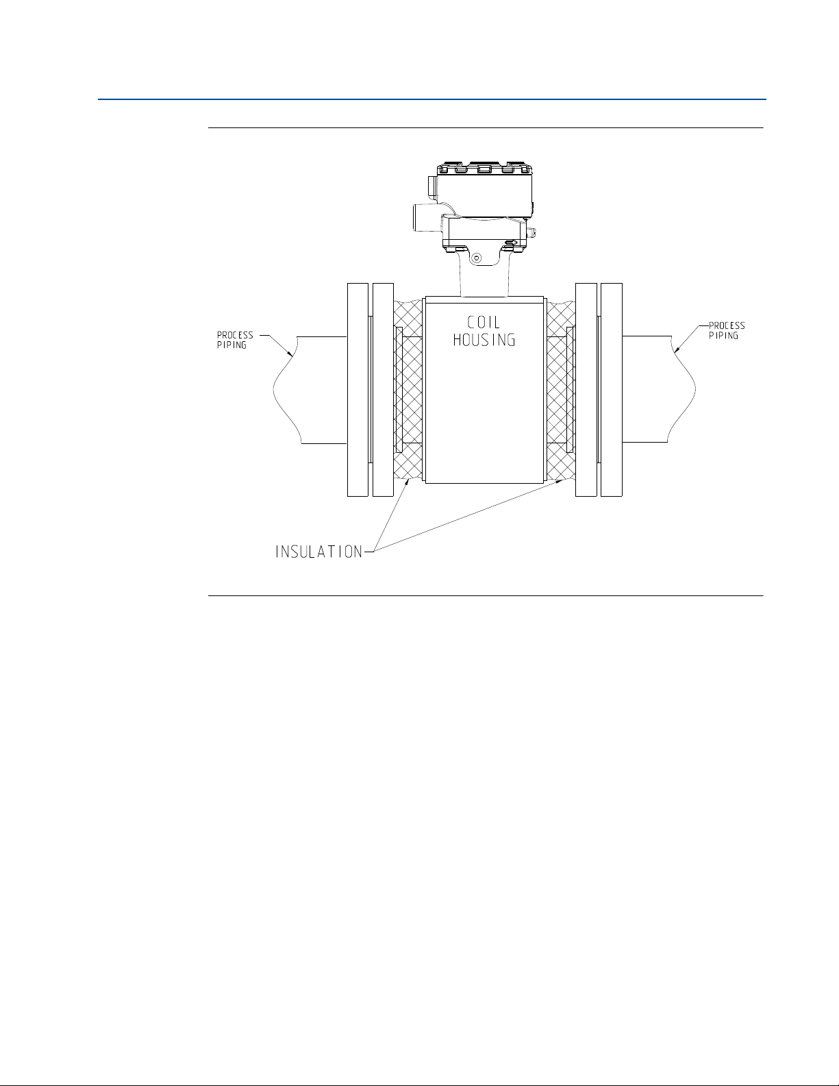
Reference Manual
00809-0100-4444, Rev AD
Figure 3-16. Insulating a Rosemount Magnetic Flowmeter for Permeation
Section 3: Advanced Installation Details
August 2015
2. When insulation of the magnetic flowmeter sensor is required due to plant safety
Advanced Installation Details
standards designed to protect personnel from contact burns, extend the insulation up
to the coil housing, covering both ends of the sensor and flanges (Figure 3-17). The
insulation should NOT cover the coil housing or the terminal junction box. Insulating
the coil housing and the terminal junction box can result in overheating of the coil
compartment and terminals, resulting in erratic/erroneous flow readings and potential
damage or failure of the meter.
55
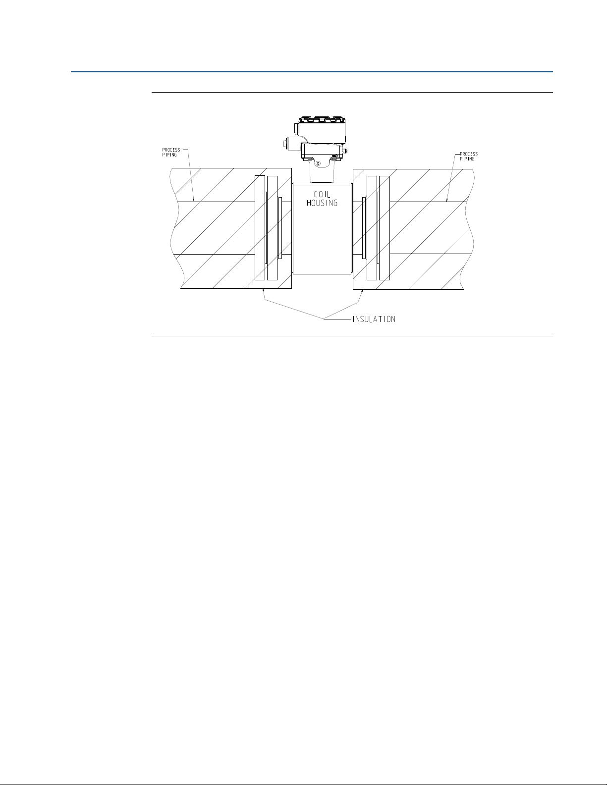
Section 3: Advanced Installation Details
August 2015
Figure 3-17. Insulating a Rosemount Magnetic Flowmeter for Safety/Plant Standards
Reference Manual
00809-0100-4444, Rev AD
56
Advanced Installation Details

Reference Manual
00809-0100-4444, Rev AD
Section 4 Operation
Introduction . . . . . . . . . . . . . . . . . . . . . . . . . . . . . . . . . . . . . . . . . . . . . . . . . . . . . . . . . . . . . . . . page 57
Local operator interface (LOI) . . . . . . . . . . . . . . . . . . . . . . . . . . . . . . . . . . . . . . . . . . . . . . . . . page 57
Field Communicator interface . . . . . . . . . . . . . . . . . . . . . . . . . . . . . . . . . . . . . . . . . . . . . . . . page 64
Process variables . . . . . . . . . . . . . . . . . . . . . . . . . . . . . . . . . . . . . . . . . . . . . . . . . . . . . . . . . . . . page 85
4.1 Introduction
The 8732EM transmitter features a full range of software functions, transmitter configurations,
and diagnostic settings. These features can be accessed through the Local Operator Interface
(LOI), a handheld Field Communicator, AMS
Configuration variables may be changed at any time; specific instructions are provided through
on-screen instructions.
Section 4: Operation
®
Device Manager, or a host control system.
August 2015
This section covers the basic features of the LOI (optional) and provides general instructions on
how to navigate the configuration menus using the optical buttons. The section also covers the
use of a Field Communicator and provides menu trees to access each function.
For detailed LOI configuration refer to Section 5: Advanced Configuration Functionality.
4.2 Local operator interface (LOI)
The optional LOI provides a communications center for the 8732EM.
The LOI allows an operator to:
Change transmitter configuration
View flow and totalizer values
Start/stop and reset totalizer values
Run diagnostics and view the results
Monitor transmitter status
Other functions
4.2.1 Basic features
The basic features of the LOI include a display window and four navigational arrow keys (see
Figure 4-1).
Operation
To activate the LOI, press the DOWN arrow two times. Use the UP, DOWN, LEFT, and RIGHT
arrows to navigate the menu structure. A map of the LOI menu structure is shown on Figure 4-2
and Figure 4-3.
57
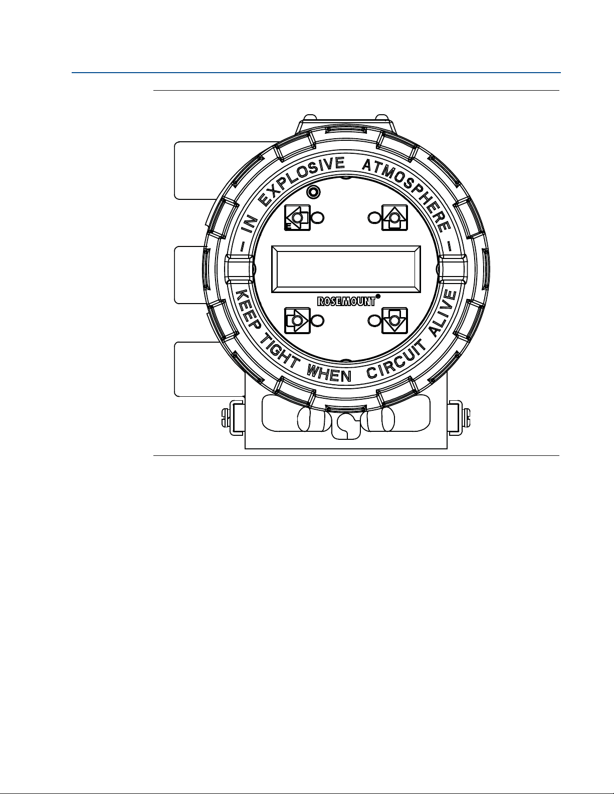
Section 4: Operation
August 2015
Figure 4-1. Local Operator Interface Keypad and Character Display
Reference Manual
00809-0100-4444, Rev AD
4.2.2 Data entry
The LOI keypad does not have alphanumeric keys. Alphanumeric and symbolic data is entered
by the following procedure. Use the steps below to access the appropriate functions.
1. Use the arrow keys to navigate the menu structure (Figure 4-2 and Figure 4-3) in order
to access the appropriate alphanumeric parameter.
2. Use the UP, DOWN or RIGHT arrow key to begin editing the parameter. (Use the LEFT
arrow key to go back without changing the value).
For numerical data, toggle through the digits 0-9, decimal point, and dash. For
alphabetical data, toggle through the letters of the alphabet A-Z, digits 0-9, and the
symbols ?, &, +, -, *, /, $, @,%, and the blank space.
3. Use the RIGHT arrow key to highlight each character you want to change and then use
the UP or DOWN arrow keys to select the value. If you go past a character that you wish
to change, keep using the RIGHT arrow key to wrap around in order to arrive at the
character you want to change.
4. Press “E” (the LEFT arrow key) when all changes are complete to save the entered
values. Press the LEFT arrow key again to navigate back to the menu tree.
58
Operation

Reference Manual
00809-0100-4444, Rev AD
4.2.3 Data entry examples
Press the DOWN arrow key twice to access the menu structures shown in Figure 4-2 and
Figure 4-3. Use the arrow keys to navigate to the desired parameters to review/change.
Parameter values are classified as table values or select values. Table values are available from a
predefined list. For parameters such as line size or flow units. Select values are integers. floating
point numbers, or character strings and are entered one character at a time using the arrow
keys for parameters such as PV URV and calibration number.
Table value example
Setting the sensor size:
1. Press the DOWN arrow key twice to access the menu. See Figure 4-2.
2. Using the arrow keys, select line size from the basic setup menu.
3. Press the UP/DOWN arrow to increase/decrease the sensor size to the next value.
4. When you reach the desired sensor size, press “E” (the left arrow).
Section 4: Operation
August 2015
5. Set the loop to manual if necessary, and press “E” again.
After a moment, the LOI will display VALUE STORED SUCCESSFULLY and then display the
selected value.
Select value example
Changing the upper range limit:
1. Press the DOWN arrow key twice to access the menu. See Figure 4-2.
2. Using the arrow keys, select PV URV from the basic setup menu.
3. Press RIGHT arrow key to position the cursor.
4. Press UP or DOWN to set the number.
5. Repeat steps 3and 4 until desired number is displayed, press “E” (the left arrow).
6. Set the loop to manual if necessary, and press “E” again.
After a moment, the LOI will display VALUE STORED SUCCESSFULLY and then display the
selected value.
4.2.4 Totalizer functionality
Operation
Start totalizer
To start the totalizer, press the DOWN arrow to display the totalizer screen and press “E” to
begin totalization. A symbol will flash in the lower right hand corner indicating that the meter is
totalizing.
59

Section 4: Operation
August 2015
Pause totalizer
To pause the totalizer, press the DOWN arrow to display the totalizer screen and press the
RIGHT arrow to pause the totalizer. This will hold the current totalizer values on the screen for
reading or recording. The totalizer will continue to run even though the values are not changing.
To unpause the totalizer, press the RIGHT arrow again. The totalizer value will instantly
increment to the correct value and continuing running.
Stop totalizer
To stop the totalizer, press the DOWN arrow to display the totalizer screen and press “E” to end
totalization. The flashing symbol will no longer display in the lower right hand corner indicating
that the meter has stopped totalizing.
Reset totalizer
To reset the totalizer, press the DOWN arrow to display the totalizer screen and follow the
procedure above to stop totalization. Once totalization has stopped, press the RIGHT arrow key
to reset the NET total value to zero. To reset the GROSS, FORWARD, and REVERSE total values,
you must change the line size. See “Basic configuration” on page 34 for details on how to
change the line size.
Reference Manual
00809-0100-4444, Rev AD
4.2.5 Display lock
The 8732EM transmitter has display lock functionality to prevent unintentional configuration
changes. The display can be locked manually or configured to automatically lock after a set
period of time.
Manual display lock
To activate hold the UP arrow for 3 seconds and then following the on-screen instructions.
When the display lock is activated, a lock symbol will appear in the lower right hand corner of
the display. To deactivate the display lock, hold the UP arrow for 3 seconds and follow the
on-screen instructions. Once deactivated, the lock symbol will no longer appear in the lower
right hand corner of the display.
Auto display lock
1. Press the DOWN arrow key twice to access the menu. See Ta bl e 4 - 2.
2. Using the arrow keys, select LOI config from the Detailed Setup menu.
3. Press DOWN arrow to highlight disp auto lock and press the RIGHT arrow to enter the
menu.
4. Press DOWN arrow to select the auto lock time.
60
5. When you reach the desired time, press “E” (the left arrow).
6. Set the loop to manual if necessary, and press “E” again.
After a moment, the LOI will display VALUE STORED SUCCESSFULLY and then display the
selected value.
Operation

Reference Manual
00809-0100-4444, Rev AD
4.2.6 Diagnostic messages
Diagnostic messages may appear on the LOI. See Table 6-1 on page 111, Table 6-2 on page 126,
and Table 6-3 on page 127 for a complete list of messages, potential causes, and corrective
actions for these messages.
4.2.7 Display symbols
When certain transmitter functions are active, a symbol will appear in the lower-right corner of
the display. The possible symbols include the following:
Display Lock
Tot a li ze r
Reverse flow
Section 4: Operation
August 2015
Continuous meter verification
Operation
61

Section 4: Operation
Diagnostics
Basic Setup
Detailed Setup
Diag Controls
Basic Diag
Advanced Diag
Variables
Trim s
Status
Empty Pipe
Process Noise
Ground/Wiring
Elec Coating
Elect Temp
Reverse Flow
Cont Meter Ver
Self Test
AO Loop Test
Pulse Out Test
Empty Pipe
Elect Temp
Flow Limit 1
Flow Limit 2
Total Limit
Ground/Wiring
Process Noise
Elec Coating
Meter Verify
4-20 mA Verify
Licensing
Empty Pipe
Elect Temp
Line Noise
5Hz SNR
37Hz SNR
Elec Coating
Signal Power
37Hz Auto Zero
Coil Current
MV Results
D/A Trim
Digital Trim
37Hz Auto Zero
Universal Trim
Coils
Electrodes
Transmitter
Analog Output
EP Control
EP Value
EP Trig Level
EP Counts
Control 1
Mode 1
High Limit 1
Low Limit 1
Hysteresis
Control 2
Mode 2
High Limit 2
Low Limit 2
Hysteresis
Total Control
Total Mode
Tot Hi Limit
Tot Low Limit
Hysteresis
EC Current Val
EC Limit 1
EC Limit 2
EC Max Value
Reset Max Val
Run Meter Ver
View Results
Sensr Baseline
Test Criteria
Measurements
4-20mA Verify
View Results
License Status
License Key
EC Current Val
EC Max Value
Manual Results
Continual Results
Manual Results
Continual Res
Valves
Reset Baseline
Recall Values
No Flow
Flowing, Full
Empty Pipe
Continual
Manual Measure
Continual Meas
Process Noise
Ground/Wiring
Elec Coating
Meter Verif
DI/DO
Device ID
Software Rev
License Key
Test Condition
Test Criteria
MV Results
Sim Velocity
ActualVelocity
Flow Sim Dev
Xmtr Cal Verify
Sensor Cal Dev
Sensor Cal
Coil Circuit
Electrode Ckt
Test Criteria
Sim Velocity
ActualVelocity
Flow Sim Dev
Coil Inductnce
Sensor Cal Dev
Coil Resist
Electrode Res
4-20 mA Expect
4-20 mA Actual
AO FB Dev
Test Condition
Test Criteria
MV Results
Sim Velocity
ActualVelocity
Flow Sim Dev
Xmtr Cal Verify
Sensor Cal Dev
Sensor Cal
Coil Circuit
Electrode Ckt
Test Criteria
Sim Velocity
ActualVelocity
Flow Sim Dev
Coil Inductnce
Sensor Cal Dev
Coil Resist
Electrode Res
4-20 mA Expect
4-20 mA Actual
1AO FB Dev
Coil Resist
Coil Inductnce
Electrode Res
Coil Resist
Coil Inductnce
Actual Velocity
Electrode Res
Coil Resist
Coil Signature
Electrode Res
ActualVelocity
Flow Sim Dev
4-20 mA Expect
4-20 mA Actual
AO FB Dev
Tag
Flow Units
Line Size
PV URV
PV LRV
Cal Number
PV Damping
PV Units
Special Units
Totalize Units
Detailed Setup
see Figure 4-3 on next page
August 2015
Figure 4-2. Local Operator Interface (LOI) Menu Tree (Diagnostics and Basic Setup)
Reference Manual
00809-0100-4444, Rev AD
62
Operation

Reference Manual
Diagnostics
Basic Setup
Detailed Setup
More Params
Output Config
LOI Config
Sig Processing
Device Info
Coil Frequency
Proc Density
PV USL
PV LSL
PV Min Span
Analog
Pulse
DI/DO Config
Totalizer
Reverse Flow
Alarm level
HART
PV URV
PV LRV
PV AO
Alarm Type
Tes t
Alarm Level
AO Diag Alarm
Pulse Scaling
Pulse Width
Pulse Mode
Tes t
DI/O 1
DO 2
Flow Limit 1
Flow Limit 2
Total Limit
Diag Alert
Totalizer Units
Total Display
Empty Pipe
Process Noise
Ground/Wiring
Elec Coating
Elect Temp
Reverse Flow
Flow Limit 1
Flow Limit 2
Total Limit
Cont Meter Ver
DI/O 1 Control
DI 1
DO 1
Reverse Flow
Zero Flow
XMTR Fault
Empty Pipe
Flow Limit 1
Flow Limit 2
Diag Alert
Total Limit 1
Control 1
Mode 1
High Limit 1
Low Limit 1
Hysteresis
Control 2
Mode 2
High Limit 2
Low Limit 2
Hysteresis
Total Control
Total Mode
Tot Hi Limit
Tot Low Limit
Hysteresis
Elec Failure
Coil Open Ckt
Empty Pipe
Reverse Flow
Ground/Wiring
Process Noise
Elect Temp
Elec Coat 1
Elec Coat 2
Cont Meter Ver
Coil Over Curr
Sensr Elec Sat
Coil Power Lim
Variable Map
Poll Address
Req Preams
Resp Preams
Burse Mode
Burst Command
Flow Display
Total Display
Language
LOI Err Mask
Disp Auto Lock
Operating Mode
SP Config
Coil Frequency
PV Damping
Lo-Flow Cutoff
Tag
Description
Message
Device ID
PV Sensor S/N
Sensor Tag
Write Protect
Revision Num
Software Rev
Final Asmbl #
PV
SV
TV
QV
Input
Output
N/A
SP Control
Samples
% Rate
Time Limit
00809-0100-4444, Rev AD
Figure 4-3. Local Operator Interface (LOI) Menu Tree (Detailed Setup)
Section 4: Operation
August 2015
Operation
63

Section 4: Operation
August 2015
4.3 Field Communicator interface
The 8732EM transmitter can be configured with a Field Communicator using HART® Protocol
gaining access to the software functions, transmitter configurations, and diagnostic settings. Refer
to the Field Communicator Manual for detailed instructions on how to connect to the device.
4.3.1 Field Communicator user interface
The 8732E device driver uses conditional formatting menus. If the diagnostic is not active, the
diagnostic will not be displayed as a menu item in the Field Communicator. The Fast Key sequence
and menu trees will be resequenced accordingly.
There are two styles of interface available for Field Communicators. The traditional interface is
shown in Figure 4-4. The device dashboard interface is shown in Figure 4-5.
Figure 4-4. Traditional Interface
Reference Manual
00809-0100-4444, Rev AD
64
The traditional interface Fast Keys are located in Table 4-1 on page 65. The corresponding menu
trees are located Figure 4-6 on page 81 and Figure 4-7 on page 82.
Operation

Reference Manual
00809-0100-4444, Rev AD
Figure 4-5. Device Dashboard Interface
Section 4: Operation
August 2015
The device dashboard interface Fast Keys are located in Table 4-2 on page 74. The corresponding
menu tree is located Figure 4-8 on page 83 and Figure 4-9 on page 84.
Table 4-1. Traditional Field Communicator Fast Keys
Func tion Traditional Fast Keys
Process variables 1, 1
Primary Variable (PV) 1, 1, 1
PV Percent of Range (PV % rnge) 1, 1, 2
PV Analog Output (AO) (PV Loop current) 1, 1, 3
Tot alizer Se tup 1, 1, 4
Tot alizer Un its 1, 1, 4, 1
Gross Total 1, 1, 4, 2
Net Total 1, 1, 4, 3
Reverse Total 1, 1, 4, 4
Start Totalizer 1, 1, 4, 5
Stop Totalizer 1, 1, 4, 6
Reset Totalizer 1, 1, 4, 7
Pulse Output 1, 1, 5
Diagnostics 1, 2
Diag Controls 1, 2, 1
Diagnostic Controls 1, 2, 1, 1
Empty Pipe 1, 2, 1, 1, --
Process Noise 1, 2, 1, 1, --
Grounding/Wiring 1, 2, 1, 1, --
Electrode Coating 1, 2, 1, 1, --
(1)
(1)
(1)
(1)
Operation
65

Section 4: Operation
August 2015
Table 4-1. Traditional Field Communicator Fast Keys (continued)
Func tion Traditional Fast Keys
Electronics Temp 1, 2, 1, 1, --
Reverse Flow 1, 2, 1, 2
Continual Ver. 1, 2, 1, 3
Coils 1, 2, 1, 3, 1 --
Electrodes 1, 2, 1, 3, 2 --
Tr an sm i tt er 1, 2, 1, 3, 3 --
Analog Output 1, 2, 1, 3, 4 --
Basic Diagnostics 1, 2, 2
Self Test 1, 2, 2, 1
AO Loop Test 1, 2, 2, 2
4 mA 1, 2, 2, 2, 1
20 mA 1, 2, 2, 2, 2
Simulate Alarm 1, 2, 2, 2, 3
Other 1, 2, 2, 2, 4
End 1, 2, 2, 2, 5
Pulse Output Loop Test 1, 2, 2, 3
Tune Empt y Pipe 1, 2, 2, 4
EP Value 1, 2, 2, 4, 1
EP Trig. Level 1, 2, 2, 4, 2
EP Counts 1, 2, 2, 4, 3
Electronics Temp 1, 2, 2, 5
Flow Limit 1 1, 2, 2, 6
Control 1 1, 2, 2, 6, 1
Mode 1 1, 2, 2, 6, 2
High Limit 1 1, 2, 2, 6, 3
Low Limit 1 1, 2, 2, 6, 4
Flow Limit Hysteresis 1, 2, 2, 6, 5
Flow Limit 2 1, 2, 2, 7
Control 2 1, 2, 2, 7, 1
Mode 2 1, 2, 2, 7, 2
High Limit 2 1, 2, 2, 7, 3
Low Limit 2 1, 2, 2, 7, 4
Flow Limit Hysteresis 1, 2, 2, 7, 5
Tot al Lim it 1, 2, 2, 8
Tot al Co ntro l 1, 2, 2, 8, 1
Tot al Mod e 1, 2, 2, 8, 2
Tot al Hig h Lim it 1, 2, 2, 8, 3
Total Low Limit 1, 2, 2, 8, 4
Reference Manual
00809-0100-4444, Rev AD
(1)
(1)
(1)
(1)
(1)
66
Operation

Reference Manual
00809-0100-4444, Rev AD
Table 4-1. Traditional Field Communicator Fast Keys (continued)
Func tion Traditional Fast Keys
Tot al Lim it Hys ter esis 1, 2, 2, 8, 5
Advanced Diagnostics 1, 2, 3
Electrode Coat 1, 2, 3, 1
EC Value 1, 2, 3, 1, 1
EC Level 1 Limit 1, 2, 3, 1, 2
EC Level 2 Limit 1, 2, 3, 1, 3
Max EC Value 1, 2, 3, 1, 4
Clear Max Electrode 1, 2, 3, 1, 5
8714i Cal Verification 1, 2, 3, 2
Run 8714i Cal Verification 1, 2, 3, 2, 1
View Results 1, 2, 3, 2, 2
Manual Results 1, 2, 3, 2, 2, 1
Tes t Con ditio n 1, 2, 3, 2, 2, 1, 1
Tes t Crit eria 1, 2, 3, 2, 2, 1, 2
8714i Test Result 1, 2, 3, 2, 2, 1, 3
Simulated Velocity 1, 2, 3, 2, 2, 1, 4
Actual Velocity 1, 2, 3, 2, 2, 1, 5
Velocity Deviation 1, 2, 3, 2, 2, 1, 6
Xmter Cal Test Result 1, 2, 3, 2, 2, 1, 7
Sensor Cal Deviation 1, 2, 3, 2, 2, 1, 8
Sensor Cal Test Result 1, 2, 3, 2, 2, 1, 9
Coil Circuit Test Result
Electrode Circuit Test Result
Continual Results 1, 2, 3, 2, 2, 2
Continuous Limit 1, 2, 3, 2, 2, 2, 1
Simulated Velocity 1, 2, 3, 2, 2, 2, 2
Actual Velocity 1, 2, 3, 2, 2, 2, 3
Velocity Deviation 1, 2, 3, 2, 2, 2, 4
Coil Signature 1, 2, 3, 2, 2, 2, 5
Sensor Cal Deviation 1, 2, 3, 2, 2, 2, 6
Coil Resistance 1, 2, 3, 2, 2, 2, 7
Electrode Resistance 1, 2, 3, 2, 2, 2, 8
mA Expected 1, 2, 3, 2, 2, 2, 9
mA Actual
mA Deviation
Sensor Signature 1, 2, 3, 2, 3
Signature Values 1, 2, 3, 2, 3, 1
(2)
(2)
Section 4: Operation
August 2015
(2)
(2)
1, 2, 3, 2, 2, 1, 10
1, 2, 3, 2, 2, 1, 11
1, 2, 3, 2, 2, 2, 10
1, 2, 3, 2, 2, 2, 11
(2)
(2)
(2)
(2)
Operation
67

Section 4: Operation
August 2015
Table 4-1. Traditional Field Communicator Fast Keys (continued)
Function Traditional Fast Keys
Coil Resistance 1, 2, 3, 2, 3, 1, 1
Coil Signature 1, 2, 3, 2, 3, 1, 2
Electrode Resistance 1, 2, 3, 2, 3, 1, 3
Re-Signature Meter 1, 2, 3, 2, 3, 2
Recall Last Saved Values 1, 2, 3, 2, 3, 3
Set Pass/Fail Criteria 1, 2, 3, 2, 4
No Flow Limit 1, 2, 3, 2, 4, 1
Flowing Limit 1, 2, 3, 2, 4, 2
Empty Pipe Limit 1, 2, 3, 2, 4, 3
Continuous Limit 1, 2, 3, 2, 4, 4
Measurements 1, 2, 3, 2, 5
Manual Measurements 1, 2, 3, 2, 5, 1
Coil Resistance 1, 2, 3, 2, 5, 1, 1
Coil Signature 1, 2, 3, 2, 5, 1, 2
Electrode Resistance 1, 2, 3, 2, 5, 1, 3
Continual Measurements 1, 2, 3, 2, 5, 2
Coil Resistance 1, 2, 3, 2, 5, 2, 1
Coil Signature 1, 2, 3, 2, 5, 2, 2
Electrode Resistance 1, 2, 3, 2, 5, 2, 3
Actual Velocity 1, 2, 3, 2, 5, 2, 4
mA Expected 1, 2, 3, 2, 5, 2, 5
mA Actual 1, 2, 3, 2, 5, 2, 6
4-20 mA Verify 1, 2, 3, 3
4-20 mA Verification 1, 2, 3, 3, 1
View Results 1, 2, 3, 3, 2
Licensing 1, 2, 3, 4
License Status 1, 2, 3, 4, 1
Process Noise Detect 1, 2, 3, 4, 1, 1 --
Line Noise Detection 1, 2, 3, 4, 1, 2 --
Electrode Coating 1, 2, 3, 4, 1, 3 --
8714i 1, 2, 3, 4, 1, 4 --
Digital I/O 1, 2, 3, 4, 1, 5 --
License Key 1, 2, 3, 4, 2
Device ID 1, 2, 3, 4, 2, 1
License Key 1, 2, 3, 4, 2, 2
Diagnostic Variables 1, 2, 4
EP Value 1, 2, 4, 1
Electronics Temp 1, 2, 4, 2
Reference Manual
00809-0100-4444, Rev AD
(1)
(1)
(1)
(1)
(1)
68
Operation

Reference Manual
00809-0100-4444, Rev AD
Table 4-1. Traditional Field Communicator Fast Keys (continued)
Function Traditional Fast Keys
Line Noise 1, 2, 4, 3
5 Hz SNR 1, 2, 4, 4
37 Hz SNR 1, 2, 4, 5
Electrode Coat 1, 2, 4, 6
EC Value 1, 2, 4, 6, 1
Max EC Value 1, 2, 4, 6, 2
Sig Power 1, 2, 4, 7
8714i Results 1, 2, 4, 8
Manual Results 1, 2, 4, 8, 1
Test Condition 1, 2, 4, 8, 1, 1
Tes t Cr iteria 1, 2, 4, 8, 1, 2
8714i Test Result 1, 2, 4, 8, 1, 3
Simulated Velocity 1, 2, 4, 8, 1, 4
Actual Velocity 1, 2, 4, 8, 1, 5
Velocity Deviation 1, 2, 4, 8, 1, 6
Xmtr Cal Test Result 1, 2, 4, 8, 1, 7
Sensor Cal Deviation 1, 2, 4, 8, 1, 8
Sensor Cal Test Result 1, 2, 4, 8, 1, 9
Coil Circuit Test Result 1, 2, 4, 8, 1, 10
Electrode Circuit Test Result 1, 2, 4, 8, 1, 11
Continual Results 1, 2, 4, 8, 2
Continuous Limit 1, 2, 4, 8, 2, 1
Simulated Velocity 1, 2, 4, 8, 2, 2
Actual Velocity 1, 2, 4, 8, 2, 3
Velocity Deviation 1, 2, 4, 8, 2, 4
Coil Signature 1, 2, 4, 8, 2, 5
Sensor Cal Deviation 1, 2, 4, 8, 2, 6
Coil Resistance 1, 2, 4, 8, 2, 7
Electrode Resistance 1, 2, 4, 8, 2, 8
mA Expected 1, 2, 4, 8, 2, 9
mA Actual 1, 2, 4, 8, 2, 10
mA Deviation 1, 2, 4, 8, 2, 11
Auto Zero Offset 1, 2, 4, 9
Tri m s 1, 2, 5
D/A Trim 1, 2, 5, 1
Scaled D/A Trim 1, 2, 5, 2
Digital Trim 1, 2, 5, 3
Section 4: Operation
August 2015
(2)
(2)
(2)
(2)
Operation
69

Section 4: Operation
August 2015
Table 4-1. Traditional Field Communicator Fast Keys (continued)
Function Traditional Fast Keys
Auto Zero 1, 2, 5, 4
Universal Trim 1, 2, 5, 5
View Status 1, 2, 6
Basic setup 1, 3
Ta g 1, 3, 1
Flow Units 1, 3, 2
PV Units 1, 3, 2, 1
Special Units 1, 3, 2, 2
Volume Unit 1, 3, 2, 2, 1
Base Volume Unit 1, 3, 2, 2, 2
Conversion Number 1, 3, 2, 2, 3
Base Time Unit 1, 3, 2, 2, 4
Flow Rate Unit 1, 3, 2, 2, 5
Line Size 1, 3, 3
PV URV 1, 3, 4
PV LRV 1, 3, 5
Calibration Number 1, 3, 6
PV Damping 1, 3, 7
Detailed setup 1, 4
Additional Parameters 1, 4, 1
Coil Drive Frequency 1, 4, 1, 1
Density Value 1, 4, 1, 2
PV USL 1, 4, 1, 3
PV LSL 1, 4, 1, 4
PV Minimum Span 1, 4, 1, 5
Configure Output 1, 4, 2
Analog Output 1, 4, 2, 1
PV URV 1, 4, 2, 1, 1
PV LRV 1, 4, 2, 1, 2
PV Loop Current 1, 4, 2, 1, 3
AO Alarm Type (PV Alrm typ) 1, 4, 2, 1, 4
AO Loop Test 1, 4, 2, 1, 5
D/A Trim 1, 4, 2, 1, 6
Scaled D/A Trim 1, 4, 2, 1, 7
Alarm Level 1, 4, 2, 1, 8
AO Diagnostic Alarm 1, 4, 2, 1, 9
Empty Pipe 1, 4, 2, 1, 9, 1 --
Reference Manual
00809-0100-4444, Rev AD
(1)
70
Operation

Reference Manual
00809-0100-4444, Rev AD
Table 4-1. Traditional Field Communicator Fast Keys (continued)
Function Traditional Fast Keys
Reverse Flow 1, 4, 2, 1, 9, 2 --
Ground/Wiring Fault 1, 4, 2, 1, 9, 3 --
High Process Noise 1, 4, 2, 1, 9, 4 --
Elect Temp Out of Range 1, 4, 2, 1, 9, 5 --
Electrode Coat Limit 2 1, 4, 2, 1, 9, 6 --
Totalizer Limit 1 1, 4, 2, 1, 9, 7 --
Flow Limit 1 1, 4, 2, 1, 9, 8 --
Flow Limit 2 1, 4, 2, 1, 9, 9 --
Cont. Meter Verification 1, 4, 2, 1, 9, 10 --
Pulse Output 1, 4, 2, 2
Pulse Scaling 1, 4, 2, 2, 1
Pulse Width 1, 4, 2, 2, 2
Pulse Mode 1, 4, 2, 2, 3
Pulse Out Loop Test 1, 4, 2, 2, 4
DI/DO Output (Digital I/O) 1, 4, 2, 3
DI/DO 1 1, 4, 2, 3, 1
Configure I/O 1 1, 4, 2, 3, 1, 1
Input 1, 4, 2, 3, 1, 1, 1
Output 1, 4, 2, 3, 1, 1, 2
Not Available/Off 1, 4, 2, 3, 1, 1, 3
DIO 1 Control 1, 4, 2, 3, 1, 2
Digital Input 1 1, 4, 2, 3, 1, 3
Digital Output 1 1, 4, 2, 3, 1, 4
DO 2 1, 4, 2, 3, 2
Flow Limit 1 1, 4, 2, 3, 3
Control 1 1, 4, 2, 3, 3, 1
Mode 1 1, 4, 2, 3, 3, 2
High Limit 1 1, 4, 2, 3, 3, 3
Low Limit 1 1, 4, 2, 3, 3, 4
Flow Limit Hysteresis 1, 4, 2, 3, 3, 5
Flow Limit 2 1, 4, 2, 3, 4
Control 2 1, 4, 2, 3, 4, 1
Mode 2 1, 4, 2, 3, 4, 2
High Limit 2 1, 4, 2, 3, 4, 3
Low Limit 2 1, 4, 2, 3, 4, 4
Flow Limit Hysteresis 1, 4, 2, 3, 4, 5
Tot al L imit 1, 4, 2, 3, 5
Tot al C ont rol 1, 4, 2, 3, 5, 1
Section 4: Operation
August 2015
(1)
(1)
(1)
(1)
(1)
(1)
(1)
(1)
(1)
Operation
71

Section 4: Operation
August 2015
Table 4-1. Traditional Field Communicator Fast Keys (continued)
Func tion Traditional Fast Keys
Tot al Mod e 1, 4, 2, 3, 5, 2
Tot al Hig h Lim it 1, 4, 2, 3, 5, 3
Total Low Limit 1, 4, 2, 3, 5, 4
Tot al Lim it Hys ter esis 1, 4, 2, 3, 5, 5
Diagnostic Status Alert 1, 4, 2, 3, 6
Electronics Failure 1, 4, 2, 3, 6, --
Coil Open Circuit 1, 4, 2, 3, 6, --
Empty Pipe 1, 4, 2, 3, 6, --
Reverse Flow 1, 4, 2, 3, 6, --
Ground/Wiring Fault 1, 4, 2, 3, 6, --
High Process Noise 1, 4, 2, 3, 6, --
Elect Temp Out of Range 1, 4, 2, 3, 6, --
Electrode Coat Limit 1 1, 4, 2, 3, 6, --
Electrode Coat Limit 2 1, 4, 2, 3, 6, --
Cont. Meter Verification 1, 4, 2, 3, 6, --
Reverse Flow 1, 4, 2, 4
Tot alizer Se tup 1, 4, 2, 5
Tot alizer Un its 1, 4, 2, 5, 1
Gross Total 1, 4, 2, 5, 2
Net Total 1, 4, 2, 5, 3
Reverse Total 1, 4, 2, 5, 4
Start Totalizer 1, 4, 2, 5, 5
Stop Totalizer 1, 4, 2, 5, 6
Reset Totalizer 1, 4, 2, 5, 7
Alarm Levels 1, 4, 2, 6
Alarm Level 1, 4, 2, 6, 1
Hi Alarm 1, 4, 2, 6, 2
Hi Sat 1, 4, 2, 6, 3
Low Sat 1, 4, 2, 6, 4
Low Alarm 1, 4, 2, 6, 5
HART Output 1, 4, 2, 7
Variable Mapping 1, 4, 2, 7, 1
PV is 1, 4, 2, 7, 1, 1
SV is 1, 4, 2, 7, 1, 2
TV is 1, 4, 2, 7, 1, 3
QV is 1, 4, 2, 7, 1, 4
Poll Address 1, 4, 2, 7, 2
Num Req Preams 1, 4, 2, 7, 3
Reference Manual
00809-0100-4444, Rev AD
(1)
(1)
(1)
(1)
(1)
(1)
(1)
(1)
(1)
(1)
72
Operation

Reference Manual
00809-0100-4444, Rev AD
Table 4-1. Traditional Field Communicator Fast Keys (continued)
Func tion Traditional Fast Keys
Num Resp Preams 1, 4, 2, 7, 4
Burst Mode 1, 4, 2, 7, 5
Burst Option 1, 4, 2, 7, 6
PV 1, 4, 2, 7, 6, --
% Range/Current 1, 4, 2, 7, 6, --
Process Vars/Current 1, 4, 2, 7, 6, --
Dynamic Vars 1, 4, 2, 7, 6, --
LOI Config 1, 4, 3
Language 1, 4, 3, 1
Flowrate Display 1, 4, 3, 2
Totalizer Display 1, 4, 3, 3
Display Lock 1, 4, 3, 4
Meter type 1, 4, 3, 5
LOI Error Mask 1, 4, 3, 6
Signal Processing 1, 4, 4
Operating Mode 1, 4, 4, 1
Man Config DSP 1, 4, 4, 2
Status 1, 4, 4, 2, 1
Samples 1, 4, 4, 2, 2
% Limit 1, 4, 4, 2, 3
Time Limit 1, 4, 4, 2, 4
Coil Drive Freq 1, 4, 4, 3
Low Flow Cutoff 1, 4, 4, 4
PV Damping 1, 4, 4, 5
Universal Trim 1, 4, 5
Device Info 1, 4, 6
Manufacturer 1, 4, 6, 1
Ta g 1, 4, 6, 2
Descriptor 1, 4, 6, 3
Message 1, 4, 6, 4
Date 1, 4, 6, 5
Device ID 1, 4, 6, 6
PV Sensor S/N 1, 4, 6, 7
Sensor Tag 1, 4, 6, 8
Write protect 1, 4, 6, 9
Revision No. 1, 4, 6, 10
Universal Rev 1, 4, 6, 10, 1--
Tran smitt er R ev 1, 4, 6, 10, 2--
Section 4: Operation
August 2015
(1)
(1)
(1)
(1)
(2)
(2)
(2)
Operation
73

Section 4: Operation
August 2015
Table 4-1. Traditional Field Communicator Fast Keys (continued)
Func tion Traditional Fast Keys
Software Rev 1, 4, 6, 10, 3--
Final Assembly # 1, 4, 6, 10, 4--
Construction Materials 1, 4, 6, 11
Flange Type 1, 4, 6, 11,1--
Flange Material 1, 4, 6, 11, 2--
Electrode Type 1, 4, 6, 11, 3--
Electrode Material 1, 4, 6, 11, 4--
Liner Material 1, 4, 6, 11, 5--
Device Reset 1, 4, 7
Review 1, 5
(1) These items are in a list format without numeric labels.
(2) To access these features, you must scroll to this option in the HART Field Communicator.
Table 4-2. Device Dashboard Fast Keys
Reference Manual
00809-0100-4444, Rev AD
(2)
(2)
(2)
(2)
(2)
(2)
(2)
(2)
Function Fast Keys
Overview 1
Device Status 1,1
Flow Rate 1,2
Analog Output Value 1,3
Upper Range Value 1,4
Lower Range Value 1,5
Run Meter Verificaiton 1,6
Meter Verification Results 1,7
Device Information 1,8
Tag 1,8,1,1
Manufacturer 1,8,1,2
Model 1,8,1,3
Final Assembly Number 1,8,1,4
Device ID 1,8,1,5
Date 1,8,1,6
Description 1,8,1,7
Message 1,8,1,8
Universal Revision 1,8,2,1
Device Revision 1,8,2,2
Software Revision 1,8,2,3
Hardware Revision 1,8,2,4
DD Revision 1,8,2,5
Sensor Serial Number 1,8,3,1
Sensor Tag 1,8,3,2
Calibration Number 1,8,3,3
Line Size 1,8,3,4
Lower Sensor Limit 1,8,3,5
Upper Sensor Limit 1,8,3,6
Minimum Span 1,8,3,7
74
Operation

Reference Manual
00809-0100-4444, Rev AD
Table 4-2. Device Dashboard Fast Keys (continued)
Function Fast Keys
Liner Material 1,8,3,8,1
Electrode Type 1,8,3,8,2
Electrode Material 1,8,3,8,3
Flange Type 1,8,3,8,4
Flange Material 1,8,3,8,5
Write Protect 1,8,4,1
Alarm Direction 1,8,4,2
Alarm Type 1,8,4,3
High Alarm 1,8,4,4
High Saturation 1,8,4,5
Low Saturation 1,8,4,6
Low Alarm 1,8,4,7
Licenses 1,8,5
Configure 2
Guided Setup 2,1
Initial Setup 2,1,1
Basic Setup 2,1,1,1
Configure Display 2,1,1,2
Special Units 2,1,1,3
Outputs 2,1,2
Analog Output 2,1,2,1
Pulse Output 2,1,2,2
Dicrete Input/Output 2,1,2,3
Totalizer 2,1,2,4
Reverse Flow 2,1,2,5
Burst Mode 2,1,2,7
Variable Mapping 2,1,2,8
Diagnostics 2,1,3
Configure Basic Diagnostics 2,1,3,1
Upgrade License 2,1,3,2
Configure Process Diagnostics 2,1,3,3
Configure Meter Verification 2,1,3,4
Re-Baseline Sensor 2,1,3,5
Alerts 2,1,4
User Alert Conifguration 2,1,4,1
Analog Alarm Configuration 2,1,4,2
Optimize Signal Processing 2,1,5
Manual Setup 2,2
Flow Units 2,2,1,2
Lower Range Value 2,2,1,3,2
Upper Range Value 2,2,1,3,3
Damping 2,2,1,3,4
Calibration Number 2,2,1,4,1
Line Size 2,2,1,4,2
Language 2,2,1,5,1
Flow Display 2,2,1,5,2
Section 4: Operation
August 2015
Operation
75

Section 4: Operation
August 2015
Table 4-2. Device Dashboard Fast Keys (continued)
Function Fast Keys
Totalizer Display 2,2,1,5,3
Display Lock 2,2,1,5,4
Density 2,2,2,1,6
Pulse Mode 2,2,2,2,2
Pulse Scaling 2,2,2,2,3
Pulse Width 2,2,2,2,4
Net Total 2,2,2,3,1
Gross Total 2,2,2,3,2
Reverse Total 2,2,2,3,3
Totalizer Control 2,2,2,3,4
Totalizer Units 2,2,2,3,5
Polling Address 2,2,3,1,1
Burst Option 2,2,3,1,3
Primary Variable 2,2,3,2,1
Secondary Variable 2,2,3,2,2
Third Variable 2,2,3,2,3
Fourth Variable 2,2,3,2,4
Discrete I/O 1 Direction 2,2,4,1,1
Dicrete Input 1 2,2,4,1,2
Discrete Output 1 2,2,4,1,3
Discrete Output 2 2,2,4,2
Flow Limit 1 2,2,4,3
High Limit 1 2,2,4,3,1
Low Limit 1 2,2,4,3,2
Limit 1 Control 2,2,4,3,3
Limit 1 Status Alert 2,2,4,3,4
Flow Limit 2 2,2,4,4
High Limit 2 2,2,4,4,1
Low Limit 2 2,2,4,4,2
Limit 2 Control 2,2,4,4,3
Limit 2 Status Alert 2,2,4,4,4
Flow Hysteresis 2,2,4,6
Totalizer Limit 2,2,4,5
Totalizer High Limit 2,2,4,5,1
Totalizer LowLimit 2,2,4,5,2
Totalizer Limit Control 2,2,4,5,3
Totalizer Limit Status Alert 2,2,4,5,4
Totalizer Hysteresis 2,2,4,7
Diagnostics Status Alert 2,2,4,8
Enable Diagnostics 2,2,5,1
License Status 2,2,5,2
Empty Pipe Value 2,2,5,3,1
Empty Pipe Trigger Level 2,2,5,3,2
Empty Pipe Counts 2,2,5,3,3
Electrode Coating Value 2,2,5,6,1
Electrode Coating Level 1 Limit 2,2,5,6,2
Electrode Coating Level 2 Limit 2,2,5,6,3
Reference Manual
00809-0100-4444, Rev AD
76
Operation

Reference Manual
00809-0100-4444, Rev AD
Table 4-2. Device Dashboard Fast Keys (continued)
Function Fast Keys
Electrode Coating Maximum Value 2,2,5,6,4
Reset Maximum Electrode Coating Value 2,2,5,6,5
Diagnostic Analog Alarm 2,2,5,9
Recall Last Baseline 2,2,6,1,5
No Flow Limit 2,2,6,3,1
Flowing Limit 2,2,6,3,2
Empty Pipe Limit 2,2,6,3,3
Continuous Meter Verification Limit 2,2,6,4,1
Enable Continuous Meter Verification Parameters 2,2,6,4,2
Coils 2,2,6,4,2,1
Electrodes 2,2,6,4,2,2
Transmitter 2,2,6,4,2,3
Analog Output (Continuous Meter Verification) 2,2,6,4,2,4
Coil Drive Frequency 2,2,8,3
Auto Zero 2,2,8,4
Digital Signal Processing (DSP) Operation 2,2,8,5
DSP Control 2,2,8,6,1
Number of Samples 2,2,8,6,2
Percent of Rate 2,2,8,6,3
Time Limit 2,2,8,6,4
Tag 2,2,9,1,1
Date 2,2,9,3,1
Description 2,2,9,3,2
Message 2,2,9,3,3
Sensor Serial Number 2,2,9,4,1
Sensor Tag 2,2,9,4,2
Liner Material 2,2,9,4,3,1
Electrode Type 2,2,9,4,3,2
Electrode Material 2,2,9,4,3,3
Flange Type 2,2,9,4,3,4
Flange Material 2,2,9,4,3,5
Alarm Type 2,2,9,5,2
Alert Setup 2,3
Flow/Totalizer Limits 2,3,1
Diagnostics 2,3,2
Flow Limit 1 2,3,3
Flow Limit 2 2,3,4
Totalizer Limit 2,3,5
Analog Alarm 2,3,6
Discrete Output Alert 2,3,7
Calibration 2,4
Universal Trim 2,4,1
Service tools 3
Alerts 3,1
Section 4: Operation
August 2015
Operation
77

Section 4: Operation
August 2015
Table 4-2. Device Dashboard Fast Keys (continued)
Reference Manual
00809-0100-4444, Rev AD
Func tion Fast Keys
Refresh Alerts 3,1,1
Active Alerts 3,1,2
Variables 3,2
Flow Rate 3,2,1,1
Pulse Output 3,2,1,2
Analog Output 3,2,1,3
Net Total 3,2,1,4,1
Gross Total 3,2,1,4,2
Reverse Total 3,2,1,4,3
Empty Pipe Value 3,2,2,1
Electronics Temperature 3,2,2,2
Coil Current 3,2,2,3
Line Noise 3,2,3,1
Electrode Coating Value 3,2,3,2
5 Hz Signal-to-Noise Ratio 3,2,3,3,1
37 Hz Signal-to-Noise Ratio 3,2,3,3,2
Signal Power 3,2,3,3,3
Continuous Meter Verification 3,2,4
Baseline Coil Resistance 3,2,4,1,1
Baseline Coil Inductance 3,2,4,1,2
Baseline Electrode Resistance 3,2,4,1,3
Continuous Sensor Measurements 3,2,4,2
Continuous Measured Coil Resistance 3,2,4,2,1
Continuous Measured Coil Inductance 3,2,4,2,2
Continuous Coil Baseline Deviation 3,2,4,2,3
Continuous Measured Electrode Resistance 3,2,4,2,4
Continuous Transmitter Measurements 3,2,4,3
Continuous Simulated Velocity 3,2,4,3,1
Continuous Actual Velocity 3,2,4,3,2
Continuous Velocity Deviation 3,2,4,3,3
Continuous Analog Output Measurements 3,2,4,4
Continuous Expected mA Value 3,2,4,4,1
Continuous Actual mA Value 3,2,4,4,2
Continuous mA Deviation 3,2,4,4,3
Tre nd s 3 ,3
Flow Rate Trend 3,3,1
Empty Pipe Trend 3,3,2
Electronics Temperature Trend 3,3,3
Line Noise Trend 3,3,4
5 Hz Signal-to-Noise Ratio Trend 3,3,5
37 Hz Signal-to-Noise Ratio Trend 3,3,6
Coil Inductance Trend 3,3,7
Coil Resistance Trend 3,3,8
Electrode Resistance Trend 3,3,9
78
Operation

Reference Manual
00809-0100-4444, Rev AD
Table 4-2. Device Dashboard Fast Keys (continued)
Section 4: Operation
August 2015
Function Fast Keys
Maintenance 3,4
Re-Baseline Sensor 3,4,1,1,4
Recall Last Baseline 3,4,1,1,5
No Flow Limit 3,4,1,2,1
Flowing Limit 3,4,1,2,2
Empty Pipe Limit 3,4,1,2,3
Manual Sensor Measurements 3,4,1,3
Manual Measured Coil Resistance 3,4,1,3,1
Manual Measured Coil Inductance 3,4,1,3,2
Manual Measured Electrode Resistance 3,4,1,3,3
Run Manual Meter Verification 3,4,1,4
Manual Meter Verification Results 3,4,1,5
Manual Coil Circuit Test Result 3,4,1,5,1,3
Manual Electrode Circuit Test Result 3,4,1,5,1,6
Manual Sensor Deviation 3,4,1,5,2,3
Manual Sensot Test Result 3,4,1,5,2,4
Manual Simulated Velocity 3,4,1,5,3,1
Manual Actual Velocity 3,4,1,5,3,2
Manual Transmitter Deviation 3,4,1,5,3,3
Manual Transmitter Test Result 3,4,1,5,3,4
Manul Test Conditions 3,4,1,5,4,1
Manual Overall Test Result 3,4,1,5,4,2
Continuous Meter Verification Limit 3,4,2,2
Enable Continuous Meter Verification Parameters 3,4,2,3
Coils 3,4,2,3,1
Electrodes 3,4,2,3,2
Transmitter 3,4,2,3,3
Analog Output (Continuous Meter Verification) 3,4,2,3,4
4-20 mA Verification 3,4,3
Run Manual 4-20 mA Verification 3,4,3,1
4 mA Measurement 3,4,3,2
12 mA Measurement 3,4,3,3
20 mA Measurement 3,4,3,4
Low Alarm Measurement 3,4,3,5
High Alarm Measurement 3,4,3,6
Analog D/A Trim 3,4,4,5
Scaled Analog D/A Trim 3,4,4,6
Electronics (Digital) Trim 3,4,5
Master Reset 3,4,6
Simulate 3,5
Analog Loop Test 3,5,1,1
Pulse Loop Test 3,5,2,1
Operation
79

Section 4: Operation
August 2015
Figure 4-6. Field Communicator Traditional Menu Tree (Basic Setup and Detailed Setup)
Home
1 Device Setup
2 PV
3 PV AO
4 PV LRV
5 PV URV
Device Setup
1 Process Variables
2 Diagnostics
3 Basic Setup
4 Detailed Setup
5 Review
Basic Setup
1 Tag
2 Flow Units
3 Line Size
4 PV URV
5 PV LRV
6 Calibration Number
7 PV Damping
Detailed Setup
1 Additional Params
2 Configure Output
3 LOI Config
4 Signal Processing
5 Universal Trim
6 Device Info
7 Device Reset
Flow Units
1 PV Units
2 Special Units
Additional Params
1 Coil Drive Freq
2 Density Value
3 PV USL
4 PV LSL
5 PV Min Span
Configure Output
1 Analog Output
2 Pulse Output
3 Digital I/O
4 Reverse Flow
5 Totalizer Setup
6 Alarm Levels
7 HART Output
LOI Config
1 Language
2 Flowrate Display
3 Totalizer Display
4 Display Lock
5 Meter Type
6 LOI Error Mask
Signal Processing
1 Operating Mode
2 Man Config DSP
3 Coil Drive Freq
4 Low Flow Cutoff
5 PV Damping
Device Info
1 Manufacturer
2 Tag
3 Descriptor
4 Message
5 Date
6 Device ID
7 PV Sensor S/N
8 Sensor Tag
9 Write protect
Revision No.
Construction Materials
Special Units
1 Volume Unit
2 Base Volume Unit
3
Conversion Number
4 Base Time Unit
5 Flow Rate Unit
Analog Output
1 PV URV
2 PV LRV
3 PV Loop Current
4 PV Alarm Type
5 AO Loop Test
6 D/A Trim
7 Scaled D/A Trim
8 Alarm Level
9 AO Diagnostic Alarm
Pulse Output
1 Pulse Scaling
2 Pulse Width
3 Pulse Mode
4 Pulse Out Loop Test
Digital I/O
1 DI/DO 1
2 DO 2
3 Flow Limit 1
4 Flow Limit 2
5 Total Limit
Diagnostic Status
6
Alert
Totalizer Setup
1 Totalizer Units
2 Gross Total
3 Net Total
4 Reverse Total
5 Start Totalizer
6 Stop Totalizer
7 Reset Totalizer
Alarm Levels
1 Alarm Level
2 Hi Alarm
3 Hi Sat
4 Low Sat
5 Low Alarm
HART Output
1 Variable Mapping
2 Poll Address
3 Num Req Preams
4 Num Resp Preams
5 Burse Mode
6 Burst Option
Man Config DSP
1 Status
2 Samples
3 % Limit
4 Time Limit
Revision No.
1 Universal Rev
2 Transmitter Rev
3 Software Rev
4 Final Assembly #
Construction Materials
1 Flange Type
2 Flange Material
3 Electrode Type
4 Electrode Material
5 Liner Material
Reference Manual
00809-0100-4444, Rev AD
AO Diagnostic Alarm
Empty Pipe
Reverse Flow
Ground/Wiring Fault
High Process Noise
Elect Temp Out of Range
Electrode Coat Limit 2
Totalizer Limit 1
Flow Limit 1
Flow Limit 2
Cont. Meter Verification
DI/DO 1
1 Configure I/O 1
2 DIO 1 Control
3 Digital Input 1
4 Digital Output 1
Configure I/O 1
Input
Output
Not Available/Off
Flow Limit 1
1 Control 1
2 Mode 1
3 High Limit 1
4 Low Limit 1
5 Flow Limit Hysteresis
Flow Limit 2
1 Control 2
2 Mode 2
3 High Limit 2
4 Low Limit 2
5 Flow Limit Hysteresis 2
Total Limit
1 Total Control
2 Total Mode
3 Total Hi Limit
4 Total Low Limit
5 Total Limit Hysteresis
Diagnostic Status Alert
Electronics Failure
Coil Open Circuit
Empty Pipe
Reverse Flow
Ground/Wiring Fault
High Process Noise
Elect Temp Out of Range
Electrode Coat Limit 1
Electrode Coat Limit 2
Cont. Meter Verification
Coil Over Current
Sensor Electrode Saturated
Coil Power Limit
Variable Mapping
1 PV is
2 SV is
3 TV is
4 QV is
Burst Option
PV
% Range/Current
Process Vars/Current
Dynamic Vars
80
Operation

Home
1 Device Setup
2 PV
3 PV AO
4 PV LRV
5 PV URV
Device Setup
1 Process Variables
2 Diagnostics
3 Basic Setup
4 Detailed Setup
5 Review
Basic Setup
1 Tag
2 Flow Units
3 Line Size
4 PV URV
5 PV LRV
6 Calibration Number
7 PV Damping
Flow Units
1 PV Units
2 Special Units
Detailed Setup
1 Additional Params
2 Configure Output
3 LOI Config
4 Signal Processing
5 Universal Trim
6 Device Info
7 Device Reset
Additional Params
1 Coil Drive Freq
2 Density Value
3 PV USL
4 PV LSL
5 PV Min Span
Special Units
1 Volume Unit
2 Base Volume Unit
3
Conversion Number
4 Base Time Unit
5 Flow Rate Unit
Configure Output
1 Analog Output
2 Pulse Output
3 Digital I/O
4 Reverse Flow
5 Totalizer Setup
6 Alarm Levels
7 HART Output
Analog Output
1 PV URV
2 PV LRV
3 PV Loop Current
4 PV Alarm Type
5 AO Loop Test
6 D/A Trim
7 Scaled D/A Trim
8 Alarm Level
9 AO Diagnostic Alarm
Pulse Output
1 Pulse Scaling
2 Pulse Width
3 Pulse Mode
4 Pulse Out Loop Test
Digital I/O
1 DI/DO 1
2 DO 2
3 Flow Limit 1
4 Flow Limit 2
5 Total Limit
6
Diagnostic Status
Alert
Totalizer Setup
1 Totalizer Units
2 Gross Total
3 Net Total
4 Reverse Total
5 Start Totalizer
6 Stop Totalizer
7 Reset Totalizer
AO Diagnostic Alarm
Empty Pipe
Reverse Flow
Ground/Wiring Fault
High Process Noise
Elect Temp Out of Range
Electrode Coat Limit 2
Totalizer Limit 1
Flow Limit 1
Flow Limit 2
Cont. Meter Verification
DI/DO 1
1 Configure I/O 1
2 DIO 1 Control
3 Digital Input 1
4 Digital Output 1
Flow Limit 1
1 Control 1
2 Mode 1
3 High Limit 1
4 Low Limit 1
5 Flow Limit Hysteresis
Flow Limit 2
1 Control 2
2 Mode 2
3 High Limit 2
4 Low Limit 2
5 Flow Limit Hysteresis 2
Total Limit
1 Total Control
2 Total Mode
3 Total Hi Limit
4 Total Low Limit
5 Total Limit Hysteresis
Diagnostic Status Alert
Electronics Failure
Coil Open Circuit
Empty Pipe
Reverse Flow
Ground/Wiring Fault
High Process Noise
Elect Temp Out of Range
Electrode Coat Limit 1
Electrode Coat Limit 2
Cont. Meter Verification
Coil Over Current
Sensor Electrode Saturated
Coil Power Limit
HART Output
1 Variable Mapping
2 Poll Address
3 Num Req Preams
4 Num Resp Preams
5 Burse Mode
6 Burst Option
Configure I/O 1
Input
Output
Not Available/Off
Variable Mapping
1 PV is
2 SV is
3 TV is
4 QV is
LOI Config
1 Language
2 Flowrate Display
3 Totalizer Display
4 Display Lock
5 Meter Type
6 LOI Error Mask
Signal Processing
1 Operating Mode
2 Man Config DSP
3 Coil Drive Freq
4 Low Flow Cutoff
5 PV Damping
Device Info
1 Manufacturer
2 Tag
3 Descriptor
4 Message
5 Date
6 Device ID
7 PV Sensor S/N
8 Sensor Tag
9 Write protect
Revision No.
Construction Materials
Revision No.
1 Universal Rev
2 Transmitter Rev
3 Software Rev
4 Final Assembly #
Construction Materials
1 Flange Type
2 Flange Material
3 Electrode Type
4 Electrode Material
5 Liner Material
Man Config DSP
1 Status
2 Samples
3 % Limit
4 Time Limit
Burst Option
PV
% Range/Current
Process Vars/Current
Dynamic Vars
Alarm Levels
1 Alarm Level
2 Hi Alarm
3 Hi Sat
4 Low Sat
5 Low Alarm
Reference Manual
00809-0100-4444, Rev AD
Figure 4-7. Field Communicator Traditional Menu Tree (Process Variables and Diagnostics)
Operation
Section 4: Operation
August 2015
81
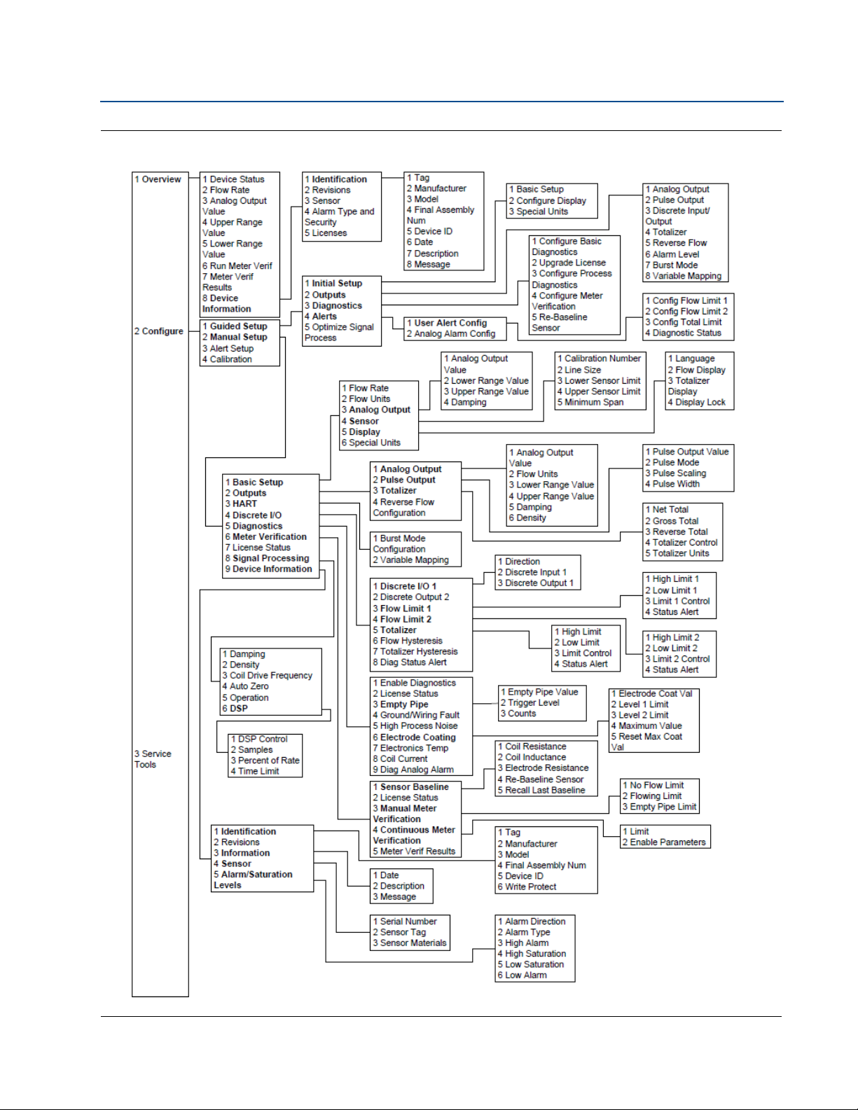
Section 4: Operation
August 2015
Reference Manual
00809-0100-4444, Rev AD
Figure 4-8. Field Communicator Dashboard Menu Tree (Overview and Configuring Guided/Manual Setup)
82
Operation
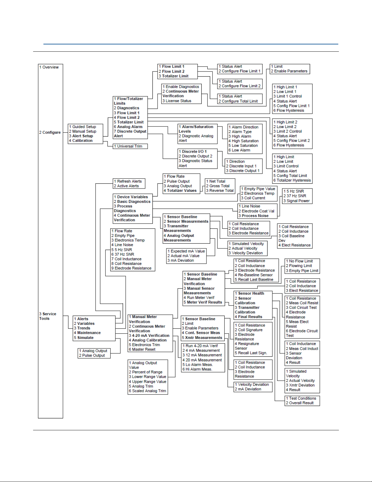
Reference Manual
00809-0100-4444, Rev AD
Section 4: Operation
Figure 4-9. Field Communicator Dashboard Menu Tree (Configuring Alert Setup and Service Tools)
August 2015
Operation
83

Section 4: Operation
August 2015
4.4 Process variables
Reference Manual
00809-0100-4444, Rev AD
LOI menu path
Traditional Fast Keys
Device dashboard
N/A
1,1
1
Process variables are available through the Field Communicator or AMS software suite. These
variables display flow in several ways that reflect your needs and the configuration of your
flowmeter. When commissioning a flowmeter, review each process variable, its function and output,
and take corrective action if necessary before using the flowmeter in a process application.
Primar y variable (PV) - The actual measured flow rate of the process fluid. Use the flow units function
to select the units for your application.
Percent of range - The process variable as a percentage of the analog output range, provides an
indication where the current flow of the meter is within the configured range of the flowmeter. For
example, the analog output range may be defined as 0 gal/min to 20 gal/min. If the measured flow is
10 gal/min, the percent of range is 50 percent.
Analog output - The analog output variable provides the analog value for the flow rate. The analog
output refers to the industry standard output in the 4-20 mA range. The analog output and 4-20 mA
loop can be verified using the Analog Feedback diagnostic capability internal to the transmitter (See
“4-20 mA loop verification” on page 119).
Pulse output - The pulse output variable provides the pulse value in terms of a frequency for the flow
rate.
4.4.1 PV - Primary variable
LOI menu path
Traditional Fast Keys
Device dashboard
The primar y variable shows the current measured flow rate. This value determines the analog output
from the transmitter.
Home screen if configured to display flow
1,1,1
1,2
4.4.2 PV - Percent of range
LOI menu path
Traditional Fast Keys
Device dashboard
The PV% range shows where in the flow range the current flow value is as a percentage of the
configured span.
Home screen if configured to display percent span
1,1,2
3,4,4,2
84
Operation

Reference Manual
00809-0100-4444, Rev AD
4.4.3 PV - Analog output
Section 4: Operation
August 2015
LOI menu path
Traditional Fast Keys
Device dashboard
The PV analog output displays the mA output of the transmitter corresponding to the measured
flow rate.
4.4.4 Pulse output
LOI menu path
Traditional Fast Keys
Device dashboard
The pulse output displays the value of the pulse signal.
N/A
1,1,3
1,3
N/A
1,1,5
3,2,1,2
Operation
85

Section 4: Operation
August 2015
Reference Manual
00809-0100-4444, Rev AD
86
Operation
 Loading...