

Page 1
Installation Guide
English – May 2002
Type 92B and 92P
Introduction
This installation guide provides instructions for
installation, startup, and adjustment. To receive a copy of
the instruction manual, contact your local Fisher Sales
Office or Sales Representative or view a copy at
www.FISHERregulators.com. For further information refer to:
Type 92B and 92P Instruction Manual, form 1329,
D100703X012.
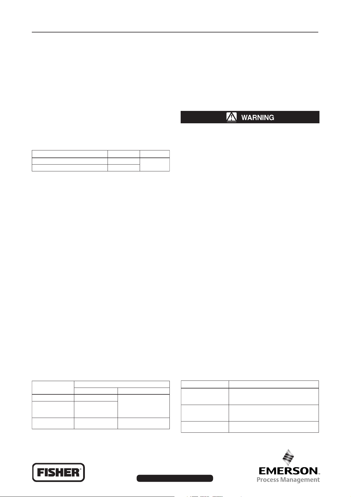
P.E.D. Categories
This product may be used as a safety accessory with
pressure equipment in the following Pressure Equipment
Directive 97/23/EC categories. It may also be used outside of the Pressure Equipment Directive using sound
engineering practice (SEP) per table below.
EZISTCUDORPSEIROGETACEPYTDIULF
)hcni-1(52NDPES
)hcni-4,3,2,2/1-1(001,08,05,04NDII,I
1
Specifications
Available Configurations
Type 92B: Pilot-operated, pressure reducing valve
with post guiding and flow to close valve plug action
Type 92P: Pilotless version of the Type 92B for
remote pressure loading
Body Sizes and End Connection Styles
See table 1
Maximum Inlet Pressures and Temperatures
See table 3
Maximum Outlet (Casing) Pressure
(1)
Cast Iron: 10,3 bar (150 psig) or body rating limits,
whichever is lower
Steel/Stainless steel: 21 bar (300 psig) or body
rating limits, whichever is lower
Proof Test Pressure
All Pressure Retaining Components have been
proof tested per Directive 97/23/EC - Annex 1,
Section 7.4
Outlet Pressure Ranges
See table 2
1. The pressure/temperature limits in this installation guide and any applicable
standard or code limitation should not be exceeded.
(1)
(1)
Minimum Differential Pressure Required for Full
(1)
Stroke
Type 92B: 1,4 bar (20 psig) with stainless steel
spring; 0,69 bar (10 psig) with Inconel spring
Type 92P: 0,34 bar (5 psig)
Type 92P Maximum Diaphragm Loading Pressure
(1)
10,3 bar (150 psig)
Installation
Only qualified personnel should install or service
a regulator. Regulators should be installed,
operated, and maintained in accordance with
international and applicable codes and
regulations, and Fisher instructions.
If the regulator vents fluid or a leak develops in
the system, it indicates that service is required.
Failure to take the regulator out of service
immediately may create a hazardous condition.
Personal injury, equipment damage, or leakage due
to escaping fluid or bursting of pressure-containing
parts may result if this regulator is overpressured
or is installed where service conditions could
exceed the limits given in the Specifications section,
or where conditions exceed any ratings of the
adjacent piping or piping connections.
To avoid such injury or damage, provide pressurerelieving or pressure-limiting devices (as required
by the appropriate code, regulation, or standard) to
prevent service conditions from exceeding limits.
Additionally, physical damage to the regulator could
result in personal injury and property damage due
to escaping fluid. To avoid such injury and damage,
install the regulator in a safe location.
Clean out all pipelines before installation of the regulator
and check to be sure the regulator has not been damaged
or has collected foreign material during shipping. For NPT
bodies, apply pipe compound to the male pipe threads. For
flanged bodies, use suitable line gaskets and approved
piping and bolting practices. Install the regulator in any
position desired, unless otherwise specified, but be sure
flow through the body is in the direction indicated by the
arrow on the body.
Table 1. Body Sizes and End Connection Styles
,EZISYDOB
)SEHCNI(ND
)1(52TPSB,TPN
)2(05,)2/1-1(04
)4(001,)3(08
norItsaCleetSsselniatSroleetS
,TPSB,TPN
dna,FF521ssalC
FR052ssalC
dnaFF521ssalC
FR052ssalC
Table 2. Outlet Pressure Ranges
ELYTSNOITCENNOCDNE
,TPSB,TPN
,FR051ssalC
,FR003ssalC
04/52/61NPdna
,FR003ssalC,FR051ssalC
04/52NPdna,61NP
www.FISHERregulators.com
EPYTTOLIP,ERUSSERPTELTUOrabGISP()
14,0ot41,0
erusserPwoL
erusserPhgiH
erutarepmeThgiH
)6ot2(
0,1ot43,0
7,1ot09,0
1,2ot0,1
2,5ot7,1
3,01ot8,4
9,6ot0,1
2,71ot5,5
)51ot5(
)52ot31(
)03ot51(
)57ot52(
)051ot07(
)001ot51(
)052ot08(
D100703XENG
Page 2
Type 92B and 92P
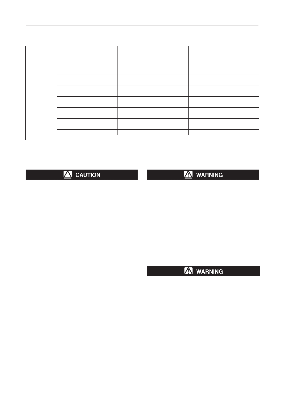
Table 3. Maximum Inlet Pressures and Temperatures
LAIRETAMYDOBNOITCENNOCDNE )GISP(rab,ERUSSERPTELNIMUMIXAM )F°(C°,ERUTAREPMETMUMIXAM
TPSB,TPN2,71)052(802)604(
norItsaC
leetS
leetSsselniatS
FF5216,8)521(871)353(
FR0522,71)052(802)604(
TPSB,TPN7,02)003(232)054(
FR0518,21)581(232)054(
FR0037,02003()
)seidob05,04,52ND(04/52/61NP7,02)003(613)006(
)seidob001,08ND(61NP8,21)581(232)054(
)seidob001,08ND(04/52NP7,02)003(613)006(
TPSB,TPN7,02)003(232)054(
FR0511,21)571(232)054(
FR0037,02)003(
)seidob05,04,52ND(04/52/61NP7,02)003(613)006(
)seidob001,08ND(61NP1,21)571(232)054(
)seidob001,08ND(04/52NP7,02)003(613)006(
)1(
)1(
.noitpodlewlaeshtiw)F°006(C°613,gnirtaesdradnatshtiw)F°054(C°232.1
613)006(
613)006(
)1(
)1(
)1(
)1(
)1(
)1(
Be sure to install Type 92B pilot above the pipeline with the adjusting screw pointing up and the
control line sloped at a downward pitch to the
main line to ensure proper condensate drainage.
Overpressure Protection
The recommended pressure limitations are stamped on
the regulator nameplate. Some type of overpressure
protection is needed if the actual inlet pressure exceeds the
maximum operating outlet pressure rating. Overpressure
protection should also be provided if the regulator inlet
pressure is greater than the safe working pressure of the
downstream equipment.
Regulator operation below the maximum pressure limitations
does not preclude the possibility of damage from external
sources or debris in the line. The regulator should be inspected
for damage after any overpressure condition.
Startup
The regulator is factory set at approximately the midpoint of
the spring range or the pressure requested, so an initial
adjustment may be required to give the desired results. With
proper installation completed and relief valves properly
adjusted, slowly open the upstream and downstream shutoff
valves.
Failure to remove accumulated condensate may
result in severe condensation induced water
hammer which can result in personal injury or
death.
Adjustment
To change the outlet pressure, remove the closing cap or
loosen the locknut and turn the adjusting screw clockwise
to increase outlet pressure or counterclockwise to decrease
pressure. Monitor the outlet pressure with a test gauge
during the adjustment. Replace the closing cap or tighten
the locknut to maintain the desired setting.
Taking Out of Service (Shutdown)
To avoid personal injury resulting from sudden
release of pressure, isolate the regulator from all
pressure before attempting disassembly.
2
Page 3

Type 92B Parts List
Key Description
20 Warning Label (Cast Iron only) (not shown)
21 Nameplate
51 Valve Body
52 Bottom Flange Assembly
53 Guide Bushing
54 Gasket
55 Cap Screw
56 Valve Plug
57 Spring
58 Seat Ring
59 Diaphragm Plate
60 Diaphragm
61 Bleed Fitting
62 Diaphragm Case
63 Cap Screw
64 Hex Nut
66 Pipe Bushing
Type 92B and 92P
30A6348-B1
Type 92P Parts List
Key Description
1 Valve Body
2 Bottom Flange Assembly
3 Guide Bushing
4 Gasket
5 Cap Screw
6 Valve Plug
7 Spring
8 Seat Ring
9 Diaphragm Plate
10 Diaphragm
11 Diaphragm Plate Plug
12 Diaphragm Case
13 Cap Screw
14 Hex Nut
15 Nameplate
16 Drive Screw
18 Pipe Bushing
20 Diaphragm Plate
Figure 1. Type 92B Main Valve Assembly
30A6955
Figure 2. Type 92P Assembly
3
Page 4

Type 92B and 92P
Type 92B Pilot
Parts List
Key Description
1 Pilot Valve Body
2 Valve Guide
3 Valve Spring
4 Valve Plug
5 Orifice
7 Valve Stem
8 Bellows Retainer
9 Bellows
10 Diaphragm
11 Lower Spring Seat
12 Spring
13 Upper Spring Seat
14 Spring Case
15 Set Screw
16 Locknut
17 Cap Screw
18 Diaphragm Gasket
19 Drive Screw
20 Nameplate
22 Pipe Nipple
24 Diaphragm Plate Assembly
74 Pipe Plug
75 Check Valve Assembly
77 Screen
BF9827-G
Figure 3. High Pressure Pilot Assembly
CJ8998-E
Figure 4. Low Pressure Pilot Assembly
©Fis her C ontro ls Inte rnati onal, I nc., 2002; All R ights Rese rved
Fisher and Fisher Regulators are marks owned by Fisher Controls International, Inc. The Emerson logo is a trade mark and service mark of Emerson Electric Co.
All other marks are the property of their respective owners.
The contents of this publication are presented for informational purposes only, and while every effort has been made to ensure their accuracy, they are not to be construed as warranties or guarantees, express
or implied, regarding the products or services described herein or their use or applicability. We reserve the right to modify or improve the designs or specifications of such products at any time without notice.
For information, contact Fisher Controls, International:
Within USA (800) 588-5853 – Outside USA (972) 542-0132
Italy – (39) 051-4190-606
Singapore – (65) 770-8320
Mexico – (52) 57-28-0888
www.FISHERregulators.com
 Loading...