

Page 1
Installation Guide
English – November 2009
67CS and 67CFS Series
Introduction
This installation guide provides instructions for
installation, startup, and adjustment. To receive a copy
of the instruction manual, contact your local Sales
Ofce or view a copy at www.sherregulators.com.
For further information refer to: 67C Series Instruction
Manual, form 5469, D102601X012.
P.E.D. Category
This product may be used as a safety accessory
with pressure equipment in the following Pressure
Equipment Directive 97/23/EC categories. It may
also be used outside of the Pressure Equipment
Directive using sound engineering practice (SEP)
per table below.
PRODUCT SIZE CATEGORIES FLUID TYPE
1/4 NPT SEP 1
Specications
Body Size and End Connection Style
1/4 NPT
Maximum Inlet Pressure (Body Rating)
67CFS Series: 17,2 bar (250 psig)
67CS Series: 27,6 bar (400 psig)
Maximum Outlet Pressure
(1)
3,4 bar (50 psig) over outlet pressure setting
Proof Test Pressure
All Pressure Retaining Components have been
proof tested per Directive 97/23/EC - Annex 1,
Section 7.4
Outlet Pressure Ranges
(1)
0 to 1,4 bar (0 to 20 psig)
0 to 2,4 bar (0 to 35 psig)
0 to 4,1 bar (0 to 60 psig)
0 to 8,6 bar (0 to 125 psig)
0 to 10,3 bar (0 to 150 psig)
Temperature Capabilities
(1)
Nitrile (NBR): -40° to 82°C (-40° to 180°F)
(1)
regulations, and Emerson Process
Management Regulator Technologies,
Inc. instructions.
If the regulator vents uid or a leak
develops in the system, it indicates that
service is required. Failure to take the
regulator out of service immediately may
create a hazardous condition.
Personal injury, equipment damage, or
leakage due to escaping uid or bursting
of pressure-containing parts may result
if this regulator is overpressured or
is installed where service conditions
could exceed the limits given in the
Specications section, or where
conditions exceed any ratings of the
adjacent piping or piping connections.
To avoid such injury or damage, provide
pressure-relieving or pressure-limiting
devices (as required by the appropriate
code, regulation, or standard) to prevent
service conditions from exceeding limits.
Additionally, physical damage to the
regulator could result in personal injury
and property damage due to escaping
uid. To avoid such injury and damage,
install the regulator in a safe location.
The internal relief valve in the
67CFSR Series regulators does not
provide full overpressure protection.
The internal relief valve is designed
for minor seat leakage only.
Clean out all pipelines before installation of the
regulator and check to be sure the regulator has not
been damaged or has collected foreign material during
shipping. For NPT bodies, apply pipe compound to the
male pipe threads. For anged bodies, use suitable
line gaskets and approved piping and bolting practices.
Install the regulator in any position desired, unless
otherwise specied, but be sure ow through the body
is in the direction indicated by the arrow on the body.
Installation
WARNING
!
Only qualied personnel should install
or service a regulator. Regulators
should be installed, operated, and
maintained in accordance with
international and applicable codes and
1. The pressure/temperature limits in this Installation Guide and any applicable standard or
code limitation should not be exceeded.
www.sherregulators.com
Note
It is important that the regulator be
installed so that the vent hole in the
spring case is unobstructed at all times.
For outdoor installations, the regulator
should be located away from vehicular
trafc and positioned so that water, ice,
and other foreign materials cannot enter
the spring case through the vent. Avoid
D103097XUS2
Page 2
2
67CS and 67CFS Series
placing the regulator beneath eaves or
downspouts, and be sure it is above the
probable snow level.
Overpressure Protection
The recommended pressure limitations are stamped on
the regulator nameplate. Some type of overpressure
protection is needed if the actual inlet pressure
exceeds the maximum operating outlet pressure rating.
Overpressure protection should also be provided if the
regulator inlet pressure is greater than the safe working
pressure of the downstream equipment.
Regulator operation below the maximum pressure
limitations does not preclude the possibility of damage
from external sources or debris in the line. The
regulator should be inspected for damage after any
overpressure condition.
Startup
The regulator is factory set at approximately the midpoint
of the spring range or the pressure requested, so an
initial adjustment may be required to give the desired
results. With proper installation completed and relief
valves properly adjusted, slowly open the upstream and
downstream shutoff valves.
Adjustment
To change the outlet pressure, remove the closing
cap or loosen the locknut and turn the adjusting
screw clockwise to increase outlet pressure or
counterclockwise to decrease pressure. Monitor
the outlet pressure with a test gauge during the
adjustment. Replace the closing cap or tighten the
locknut to maintain the desired setting.
Taking Out of Service (Shutdown)
WARNING
!
To avoid personal injury resulting from
sudden release of pressure, isolate
the regulator from all pressure before
attempting disassembly.
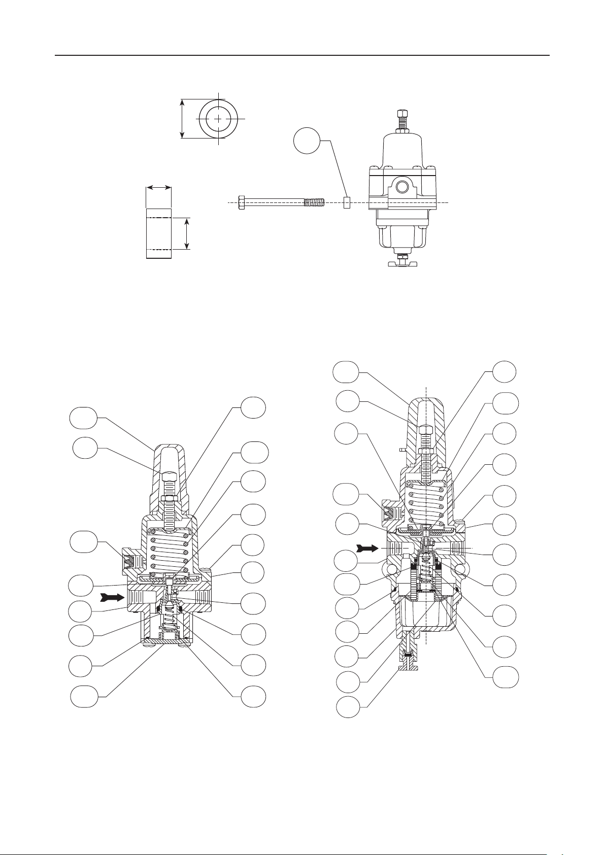
Parts List
Types 67CS and 67CSR
Key Description
1 Body
3 Flange Screw
(1)
4
O-Ring
7 Spring Case
(1,2)
10
Valve Cartridge
(1,2)
11
Valve Plug
(1,2)
12
Valve Spring
(1,2)
13
Valve Retainer
(1,2)
14
O-Ring
(1,2)
15
Soft Seat
(1)
16
Diaphragm Assembly
17 Spring
18 Adjusting Screw
19 Locknut
20 Upper Spring Seat
33 Closing Cap
39 Bottom Plate
45 Vent Screen
Types 67CFS and 67CFSR
Key Description
1 Body
2 Drain Valve
3 Flange Screw
(1)
4
O-Ring
5 Dripwell
(1)
6
Filter Element
7 Spring Case
9 Filter Retainer
(1,2)
10
Valve Cartridge
(1,2)
11
Valve Plug
(1,2)
12
Valve Spring
(1,2)
13
Valve Retainer
(1,2)
14
O-Ring
(1,2)
15
Soft Seat
(1)
16
Diaphragm Assembly
17 Spring
18 Adjusting Screw
19 Locknut
20 Upper Spring Seat
(1)
26
Filter Gasket
33 Closing Cap
34 Spacer
37 Thrust Washer
45 Vent Screen
1. Recommended Spare Part
2. Valve Cartridge Assembly includes keys 10, 11, 12, 13, 14, and 15.
Page 3
3
67CS and 67CFS Series
33
45
39
18
1
7
3
4
16
13
12
14
11
15
17
19
10
20
18
33
16
1
5
6
9
2
10
19
18
17
15
11
14
12
13
7
45
20
31
26
37
3
4
IN
34
13
(0.50)
OD
SPACER OUTER
DIAMETER
6,4
(0.25)
8,1
ID
(0.32)
SPACER WIDTH AND
INNER DIAMETER
Figure 1. Types 67CFS and 67CFSR Spacer Diameter and Installation
SPACER
B2697
INCHES
(mm)
GE03521
Figure 2. Types 67CS and 67CSR Assembly
40C1728
Figure 3. Types 67CFS and 67CFSR Assembly
Page 4

67CS and 67CFS Series
Industrial Regulators
Emerson Process Management
Regulator Technologies, Inc.
USA - Headquarters
McKinney, Texas 75069-1872 USA
Tel: 1-800-558-5853
Outside U.S. 1-972-548-3574
Asia-Pacic
Shanghai, China 201206
Tel: +86 21 2892 9000
Europe
Bologna, Italy 40013
Tel: +39 051 4190611
Middle East and Africa
Dubai, United Arab Emirates
Tel: +971 4811 8100
For further information visit www.sherregulators.com
The Emerson logo is a trademark and service mark of Emerson Electric Co. All other marks are the property of their prospective owners. Fisher is a mark owned by Fisher Controls, Inc.,
a business of Emerson Process Management.
The contents of this publication are presented for informational purposes only, and while every effort has been made to ensure their accuracy, they are not to be construed as warranties
or guarantees, express or implied, regarding the products or services described herein or their use or applicability. We reserve the right to modify or improve the designs or specications
of such products at any time without notice.
Emerson Process Management does not assume responsibility for the selection, use or maintenance of any product. Responsibility for proper selection, use and maintenance of any
Emerson Process Management product remains solely with the purchaser.
Natural Gas Technologies
Emerson Process Management
Regulator Technologies, Inc.
USA - Headquarters
McKinney, Texas 75069-1872 USA
Tel: 1-800-558-5853
Outside U.S. 1-972-548-3574
Asia-Pacic
Singapore, Singapore 128461
Tel: +65 6777 8211
Europe
Bologna, Italy 40013
Tel: +39 051 4190611
Gallardon, France 28320
Tel: +33 (0)2 37 33 47 00
TESCOM
Emerson Process Management
Tescom Corporation
USA - Headquarters
Elk River, Minnesota 55330-2445 USA
Tel: 1-763-241-3238
Europe
Selmsdorf, Germany 23923
Tel: +49 (0) 38823 31 0
©Emerson Process Management Regulator Technologies, Inc., 2004, 2009; All Rights Reserved
 Loading...