

Page 1
Bulletin 62.3:670
February 2015
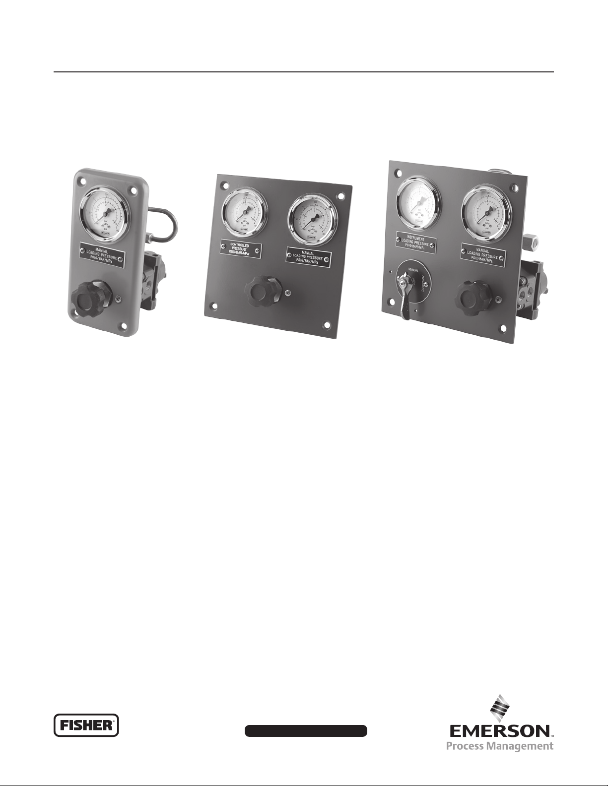
670 Series Panel-Mounted Loading Regulators
P1127_670
1-GAUGE PANEL
(671 AND 670 SERIES)
Figure 1. Typical Panel Layouts
P1128_670G-3
2-GAUGE PANEL
(670 SERIES)
Introduction
The Types 670, 671, 674 and 675 panel-mounted
loading regulators (Figures 1, 2, 3 and 6) are compact,
rugged units used primarily for manually loading
pressure-balanced gas regulators and providing
manual control for diaphragm actuator control valves.
Applications include remote control of gas pressure to
burners in reneries, power plants and various process
furnaces. The Types 670 and 675 units use the
Type 67CR or 67CFR pressure regulator, the Type 671
unit uses the Type 912 pressure regulator and the
Type 674 unit uses the Type 1301F pressure regulator.
Three basic panels are available within the product
line as shown in Figures 1 and 6, each having one
pressure regulator connected to one or two gauges
P1130_670GV
2-GAUGE PANEL WITH
CHANGEOVER VALVE
(670 SERIES)
or two gauges and a changeover valve. A single
gauge typically shows loading pressure to the control
valve. With two gauges, one gauge shows the loading
pressure and the other gauge can be connected to
show downstream control pressure or any other
pressure up to 300 psig / 20.7 bar. Manual backup
of pneumatic controllers can be handled with those
670 Series units having a changeover valve. With it
the operator selects either the automatic controller
output (displayed on one gauge) or the manual
loader output (displayed on the other gauge and
adjusted by the handwheel) as the signal to the
control valve actuator.
www.fisherregulators.com
D200027X012
Page 2

Bulletin 62.3:670
Specications
This section lists the specications for the 670 Series panel-mounted loading regulators. Factory specications
are stamped on the nameplate fastened on the regulator at the factory.
Available Congurations
See Table 1
End Connections
Inlet: 1/4 NPT internal
Outlet: Types 670 and 675—1/4 NPT internal;
Type 671—3/8 NPT internal;
Type 674—1/4 NPT internal
Maximum Allowable Inlet Pressure
Without Changeover Valve: 250 psig / 17.2 bar
With Changeover Valve: 50 psig / 3.4 bar
Maximum Outlet Pressure
See Table 1
Maximum Emergency Outlet Pressure
See Table 1
Outlet Pressure Ranges
Types 670 and 675
(1)
: 3 to 18 psig / 0.21 to 1.2 bar
5 to 30 psig / 0.34 to 2.1 bar; 30 to 50 psig / 2.1 to
3.4 bar; and 35 to 80 psig / 2.4 to 5.5 bar except
35 to 50 psig / 2.4 to 3.4 bar with change over valve
Type 671: 0 to 1 psig / 0 to 0.07 bar; 0 to 5 psig /
0 to 0.34 bar
Type 674: 10 to 75 psig / 0.69 to 5.2 bar;
50 to 150 psig / 3.4 to 10.3 bar;
100 to 225 psig / 6.9 to 15.5 bar
Pressure Registration
Internal
Construction Materials
Panel Tubing: Copper, PVC-coated copper,
aluminum or 316 (316 Stainless steel)
Regulator Body
Types 670 and 675: Die-cast aluminum
Type 671: Die-cast zinc
Type 674: Brass
Regulator Spring Case
Types 670 and 675: Die-cast zinc/Stainless steel
Type 671: Die-cast zinc
Type 674: Forged brass or steel
Panel
Types 670, 670F and 671: Zinc
Types 670FG, 670G, 670FGV and 670GV: Steel
Handwheel: Die-cast aluminum
Construction Materials (continued)
Other Regulator Parts
Diaphragm: Nitrile (NBR)
Valve Disk: Nitrile (NBR)
Diaphragm Plate: Plated steel
Spring: Plated steel
Filter Cartridge (Type 67CFR Regulator Only):
Cellulose (standard) or Stainless steel or Brass
Temperature Capabilities
-20 to 180°F / -29 to 82°C
Pressure Gauges
Connection: 1/8 NPT external tting on back
of case
Ranges: Standard ranges shown in Table 2 with
other ranges available upon request
Face Colors: White with black numerals
Case Color: Black
Gauge Identication: White engraving on black
laminated plastic plate below gauge indicates units
and function. Up to 16 characters per line, 3 lines,
are available.
Regulator Port Diameters
Types 670 and 675: 0.125 in. / 3.2 mm
Type 671: 0.073 in. / 1.9 mm (standard);
0.094 in. / 2.4 mm (optional)
Type 674: 0.078 in. / 2.0 mm
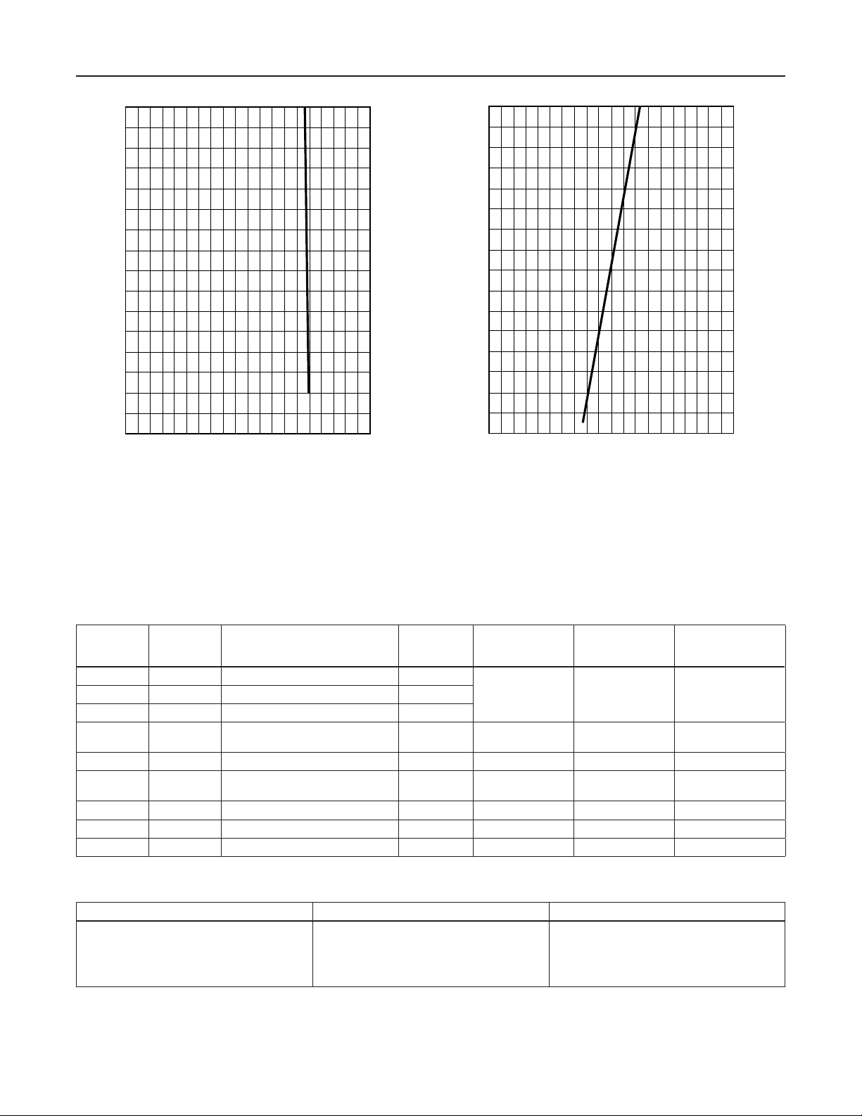
Operating Inuences
670 Series: As shown in Figure 4, output pressure
(2)
changes less than 5 psig / 0.34 bar when the input
pressure changes between 20 to 140 psig / 1.4 to
9.7 bar
Type 671: As shown in Figure 5, output pressure
changes less than 1 in. w.c. / 2 mbar when the
input pressure changes between 20 to 140 psig /
1.4 and 9.7 bar
Regulator Flow Capacity
See appropriate pressure regulator bulletin
Internal Relief for Pressure Regulators
Adequate for relieving only minor build-up
situations. Refer to the appropriate pressure
regulator bulletin to determine if external relief
is required.
1. These pressure ranges are recommended, but all springs used in the Type 67CR or 67CFR regulators can be adjusted down to 0 psig / 0 bar.
2. Dened in ISA Standard S51.1-1979.
2
Page 3
SCREENED
BLEED
ORIFICE
Bulletin 62.3:670
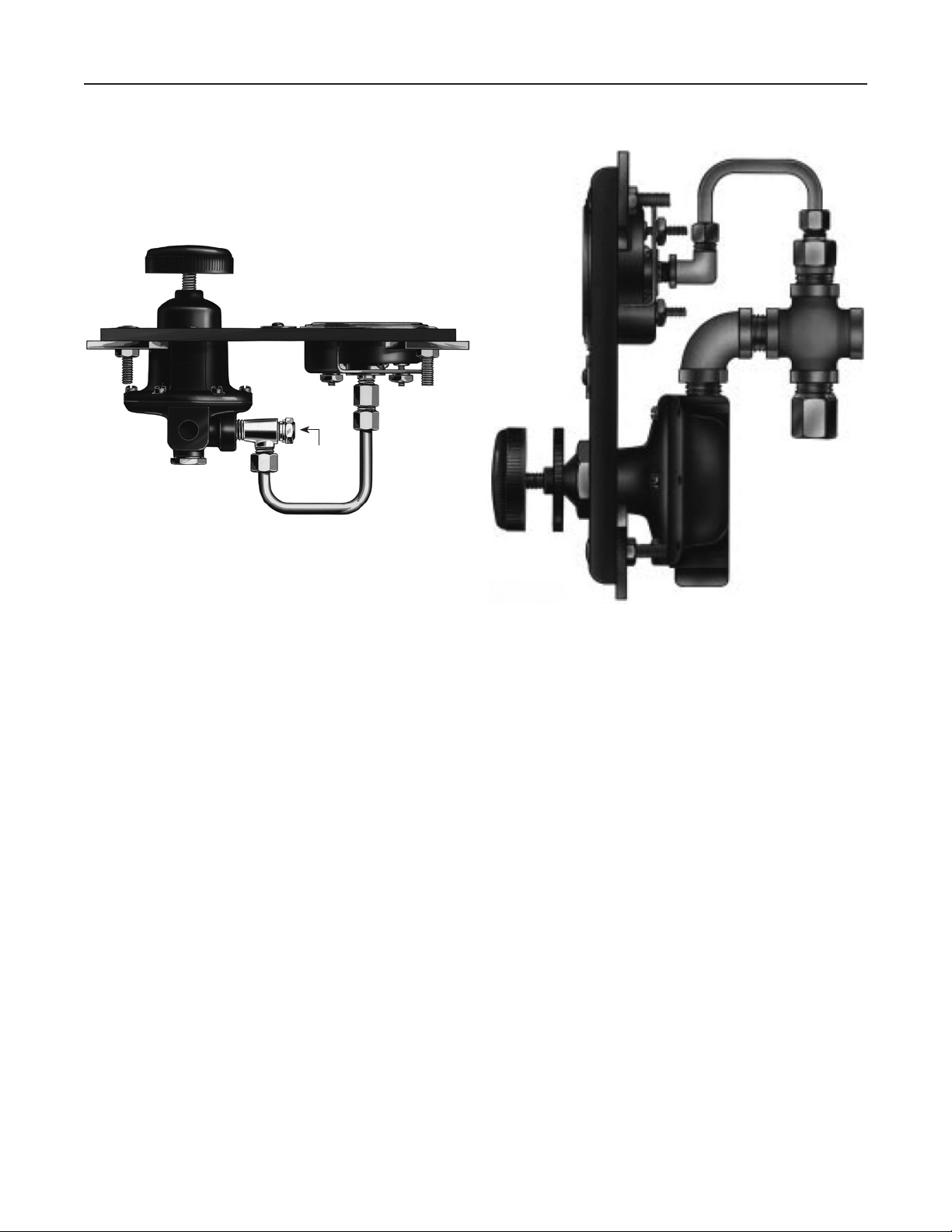
W0532
Figure 2. Type 670 Panel Loader
Features
• Control Flexibility—With a changeover valve, the
operator can deliver pressure to the control valve
from the manual loader, a controller or bypass the
panel completely.
• Gauge Identication—Big, clear, white-on-black
labels (see Figure 1) show gauge function and
units at a glance.
• Convenient Fingertip Control—Turn the panel-
mounted handwheel clockwise to increase or
counterclockwise to decrease pressure to the
control valve while watching the high visibility
black-on-white gauges.
W6110-1/IL
Figure 3. Side View of Type 671 Panel Loader Using
Type 912 Regulator
• Easy Connections—Unit comes with all the
hardware necessary to connect the loading
pressure gauge to the pressure regulator.
• Versatility—Pressure regulators are suitable for
a variety of gaseous uids including natural gas,
propane and air.
• Compact Size—The slim proles of the regulators
are ideal for installations where space behind the
panel is limited.
3
Page 4
Bulletin 62.3:670
A2554/IL
160
140
120
100
80
60
INLET PRESSURE, psig
40
20
5 /
0.34
10 /
0.69
15 /
1.0
OUTLET PRESSURE, psig / bar
NOTE:
TEST CONDUCTED USING A CONSTANT FLOW RATE OF
50 STANDARD CUBIC FEET PER HOUR AT 60°F AND
14.7 psia (1.3 NORMAL CUBIC METERS PER HOUR AT 0°C
AND 1.01325 bar, ABSOLUTE)
20 /
1.4
25 /
1.7
11.0
9.7
8.3
6.9
5.5
4.1
2.8
1.4
INLET PRESSURE, bar
160
140
120
100
80
60
INLET PRESSURE, psig
40
20
0
A2553/IL
9 /
22
10 /
25
11 /
28
OUTLET PRESSURE, IN. W.C. / mbar
NOTE:
TEST CONDUCTED USING A CONSTANT FLOW RATE OF
50 STANDARD CUBIC FEET PER HOUR AT 60°F AND
14.7 psia (1.3 NORMAL CUBIC METERS PER HOUR AT 0°C
AND 1.01325 bar, ABSOLUTE)
12 /
30
13 /
32
11.0
9.7
8.3
6.9
5.5
4.1
2.8
1.4
INLET PRESSURE, bar
Figure 4. Pressure Variation of Type 67CR Regulator
Figure 5. Pressure Variation of Type 912 Regulator
Table 1. Available Congurations
TYPE
NUMBER
NUMBER OF
GAUGE
DESCRIPTION
REGULATOR
TYPE
NUMBER
670 1 Basic 1-gauge panel 67CR
670FG 2 2-gauge panel; regulator has lter 67CFR
670FGV 2
2-gauge panel with 3-way
changeover valve; regulator has lter
67CFR 50 psig / 3.4 bar 50 psig / 3.4 bar 55 psig / 3.8 bar
670G 2 Basic 2-gauge panel 67CR 250 psig / 17.2 bar 100 psig / 6.9 bar 110 psig / 7.6 bar
670GV 2
2-gauge panel with 3-way or 4-way
changeover valve
67CR 50 psig / 3.4 bar 50 psig / 3.4 bar 55 psig / 3.8 bar
671 1 Basic 1-gauge panel 912N 250 psig / 17.2 bar 5 psig / 0.34 bar 10 psig / 0.69 bar
674G 2 Basic 2-gauge panel 1301F 6000 psig / 414 bar 225 psig / 15.5 bar 250 psig / 17.2 bar
675G 2 Basic 2-gauge panel 67CR 250 psig / 17.2 bar 100 psig / 6.9 bar 110 psig / 7.6 bar
MAXIMUM
INLET
PRESSURE
250 psig / 17.2 bar 100 psig / 6.9 bar 110 psig / 7.6 bar670F 1 1-gauge panel; regulator has lter 67CFR
MAXIMUM
OUTLET
PRESSURE
MAXIMUM
EMERGENCY
OUTLET PRESSURE
Table 2. Pressure Gauge Ranges - Triple Scale
psig Pa bar
0 to 10
0 to 30
0 to 60
0 to 160
0 to 300
0 to 0.6 K
0 to 0.2 M
0 to 0.4 M
0 to 1.1 M
0 to 2 M
0 to 0.69
0 to 2.1
0 to 4.1
0 to 11.0
0 to 20.7
4
Page 5

Bulletin 62.3:670
IN
B
MANUAL
LOADING PRESSURE
PSIG/BAR/MPa
A
6.80 /
173
GE03276
8.00 /
203
TYPE 670
8.00 /
203
6.80 /
GE13900
173
C
(MAXIMUM)
B
A
INTRUMENT
LOADING PRESSURE
LBS PER SQ IN.
MANUAL
AUTOMATIC
IN
D
F
OFF
B
GE02157
MANUAL
LOADING PRESSURE
LBS PER SQ IN.
INCREASE
6.80 /
173
IN
C
F
8.00 /
203
ED
TYPE NO.
SERIAL NO.
A
TYPE 670GV
1/4 NPT
CONTROL PRESSURE
MONITORING
8.61 /
219
1/4 NPT
ACTUATOR CONNECTION
C
TYPE 670G
IN
D
F
1.38 /
E E
8.61 /
1/4 NPT
SUPPLY CONNECTION
35
3.25 /
83
219
1.38 /
35
0.12 to 0.75 /
3.0 to 19
PANEL
2.62 /
1
DC3352-B
NOTE:
ENVELOPE DIMENSIONS ± 0.25 IN. / ± 6.4 mm
1
NOTE:
A0879-2
67
MAXIMUM
1.62 /
41
2.12 /
54
4.75 /
121
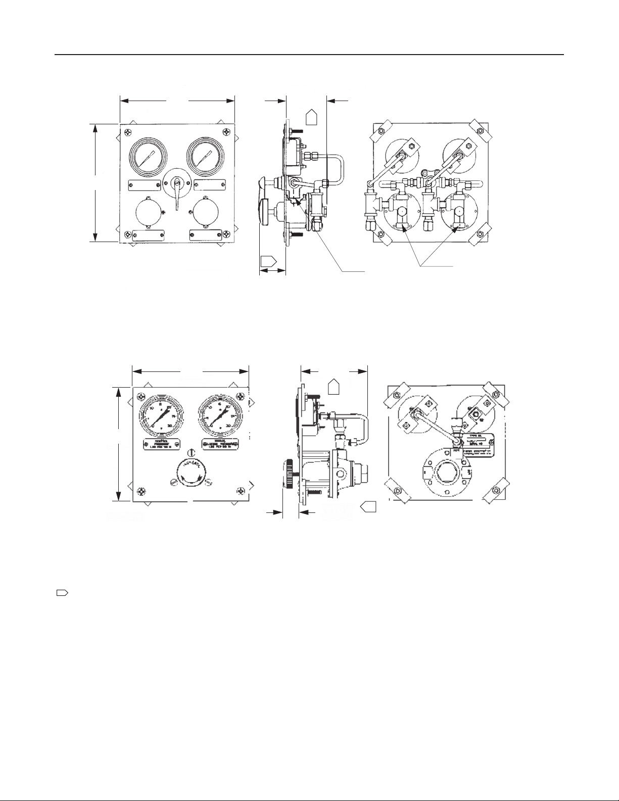
TYPE 671 DIMENSIONS
Figure 6. Dimensions
Table 3. Dimension Table
TYPE NUMBER
670
670F
670G
670FG
670GV
670FGV
671
1. Dimension F refers to the depth to which those regulators with lters extend behind the panel.
A B C D E F
In. mm In. mm In. mm In. mm In. mm In. mm In. mm
4.00
102
4.00
8.00
8.00
8.00
8.00
4.00
102
203
203
203
203
102
2.80
2.80
6.80
6.80
6.80
6.80
2.80
71
71
173
173
173
173
71
2.55
2.70
2.01
2.40
2.01
2.40
2.60
65
69
51
61
51
61
66
2.15
2.00
2.69
2.40
2.69
2.40
2.10
3/8-18 NPT
1/4-18 NPT
DIMENSION
55
51
68
61
68
61
53
0.72
- - - -
2.72
- - - -
0.72
- - - -
- - - -
4.00 /
102
2.00 /
51
18
- - - 69
- - - 18
- - - -
- - - -
3.66
6.00
5.73
7.10
4.20
7.10
- - - -
IN. /
mm
(1)
93
152
146
180
107
180
- - - -
Panel Count
3.25 x 7.25
3.25 x 7.25
7.25 x 7.25
7.25 x 7.25
7.25 x 7.25
7.25 x 7.25
3.25 x 7.25
83 x 184
83 x 184
184 x 184
184 x 184
184 x 184
184 x 184
83 x 184
5
Page 6
Bulletin 62.3:670
9.00 /
229
11B4602-A
9.00 /
229
8.00 /
203
4.88 /
124
1
2.38 /
1
60
MAXIMUM
TYPE 675G DIMENSIONS
5.50 /
140
ACTUATOR
DIAPHRAGM
CONNECTION
1
SUPPLY CONNECTION
8.00 /
203
4DA6615-B
NOTE:
1
ENVELOPE DIMENSIONS ± 0.25 IN. / ± 6.4 mm
B2405/IL
Figure 6. Dimensions (continued)
1.50 / 38
MAXIMUM
TYPE 674G DIMENSIONS
1
IN. /
mm
6
Page 7

Bulletin 62.3:670
Installation
Dimensions for installation clearances are shown in
Figure 6.
Ordering Guide
Type (See Table 1 for Construction details)
(Select One)
670
670F
670FG
670FGV
670G
670GV
671
674G
675G
Outlet Pressure Range (Select One)
Types 670 and 675
3 to 18 psig / 0.21 to 1.2 bar
5 to 30 psig / 0.34 to 2.1 bar
30 to 50 psig / 2.1 to 3.4 bar
35 to 80 psig / 2.4 to 5.5 bar except 35 to
50 psig / 2.4 to 3.4 bar with change over valve
Type 671
0 to 1 psig / 0 to 0.07 bar
0 to 5 psig / 0 to 0.34 bar
Type 674
10 to 75 psig / 0.69 to 5.2 bar
50 to 150 psig / 3.4 to 10.3 bar
100 to 225 psig / 6.9 to 15.5 bar
Ordering Information
When ordering, complete the ordering guide on this
page. Refer to the Specications section on page 2.
Review the description to the right of each specication
and the information in each referenced table or gure.
Specify your choice whenever a selection is offered.
Pressure Gauge Ranges
0 to 10 psig / 0 to 0.6 kPa / 0 to 0.69 bar
0 to 30 psig / 0 to 0.2 MPa / 0 to 2.1 bar
0 to 60 psig / 0 to 0.4 MPa / 0 to 4.1 bar
0 to 160 psig / 0 to 1.1 MPa / 0 to 11.0 bar
0 to 300 psig / 0 to 2 MPa / 0 to 20.7 bar
Changeover Valve
Yes
No
(1)
(Select One)
1. Other ranges available upon request.
7
Page 8

Bulletin 62.3:670
Industrial Regulators
Emerson Process Management
Regulator Technologies, Inc.
USA - Headquarters
McKinney, Texas 75070 USA
Tel: +1 800 558 5853
Outside U.S. +1 972 548 3574
Asia-Pacic
Shanghai 201206, China
Tel: +86 21 2892 9000
Europe
Bologna 40013, Italy
Tel: +39 051 419 0611
Middle East and Africa
Dubai, United Arab Emirates
Tel: +971 4811 8100
For further information visit www.fisherregulators.com
The Emerson logo is a trademark and service mark of Emerson Electric Co. All other marks are the property of their prospective owners. Fisher is a mark owned by Fisher Controls International LLC,
a business of Emerson Process Management.
The contents of this publication are presented for informational purposes only, and while every effort has been made to ensure their accuracy, they are not to be construed as warranties or
guarantees, express or implied, regarding the products or services described herein or their use or applicability. We reserve the right to modify or improve the designs or specications of such
products at any time without notice.
Emerson Process Management Regulator Technologies, Inc. does not assume responsibility for the selection, use or maintenance of any product. Responsibility for proper selection, use and
maintenance of any Emerson Process Management Regulator Technologies, Inc. product remains solely with the purchaser.
Natural Gas Technologies
Emerson Process Management
Regulator Technologies, Inc.
USA - Headquarters
McKinney, Texas 75070 USA
Tel: +1 800 558 5853
Outside U.S. +1 972 548 3574
Asia-Pacic
Singapore 128461, Singapore
Tel: +65 6770 8337
Europe
Bologna 40013, Italy
Tel: +39 051 419 0611
Chartres 28008, France
Tel: +33 2 37 33 47 00
Middle East and Africa
Dubai, United Arab Emirates
Tel: +971 4811 8100
TESCOM
Emerson Process Management
Tescom Corporation
USA - Headquarters
Elk River, Minnesota 55330-2445, USA
Tels: +1 763 241 3238
+1 800 447 1250
Europe
Selmsdorf 23923, Germany
Tel: +49 38823 31 287
Asia-Pacic
Shanghai 201206, China
Tel: +86 21 2892 9499
©Emerson Process Management Regulator Technologies, Inc., 1992, 2015; All Rights Reserved
 Loading...