

Emerson 289 Installation Guide
Installation Guide
English – September 2009
289 Series
Introduction
This installation guide provides instructions for installation, startup,
and adjustment. To receive a copy of the instruction manual, contact
your local Sales Ofce or view a copy at www.emersonprocess.com/
regulators. For further information refer to: 289 Series Instruction
Manual (form 1724, D100280X012).
P.E.D. Category
This product may be used as a pressure accessory with
pressure equipment in the following Pressure Equipment
Directive 97/23/EC categories. It may also be used outside
of the Pressure Equipment Directive using sound engineering
practice (SEP) per table below.
PRODUCT SIZE CATEGORIES FLUID TYPE
Types 289A, 289U, 289L,
289HH, and 289H - 1 NPT
Type 289H - 2 NPT I
SEP
1
Specications
Available Congurations
Types 289A, 289H, 289HH, 289L, 289U
Body Sizes and End Connection Styles
Types 289A and 289U: 1/4 NPT
Type 289H: 1 or 2 NPT
Type 289HH: 1 NPT
Type 289L: 3/4 or 1 NPT
Maximum Allowable Inlet Pressure
Type 289A: 3,1 bar (45 psig)
Type 289H (1 NPT): 6,9 bar (100 psig)
Type 289H 2 NPT: 1,7 bar (25 psig)
Type 289HH: 6,9 bar (100 psig)
Type 289L: 0,48 bar (7 psig)
Type 289U: 0,69 bar (10 psig)
Proof Test Pressure
All Pressure Retaining Components have been proof
tested per Directive 97/23/EC - Annex 1, Section 7.4
Spring Range (Pressure Settings)
Type 289A: 0,20 to 0,90 bar (3 to 13 psig),
0,76 to 1,5 bar (11 to 22 psig)
Type 289H (DN 25 (NPS 1)): 69 to 310 mbar (1 to 4.5 psig),
0,28 to 1,03 bar (4 to 15 psig), 0,69 to 1,4 bar (10 to 20 psig),
1,03 to 3,4 bar (15 to 50 psig)
Type 289H (DN 50 (NPS 2)): 17 to 45 mbar (7 to
18-inches w.c.), 35 to 155 mbar (0.5 to 2.25 psig),
21 to 483 mbar (1.75 to 7 psig), 0,28 to 0,69 bar (4 to 10 psig)
Type 289HH: 3,1 to 5,2 bar (45 to 75 psig)
Type 289L: 7 to 20 mbar (3 to 8-inches w.c.),
12 to 45 mbar (5 to 18-inches w.c.),
25 to 45 mbar (10 to 18-inches w.c.),
30 to 100 mbar (12 to 40-inches w.c.)
Type 289U: 12 to 62 mbar (5 to 25-inches w.c.),
50 to 206 mbar (20-inches w.c. to 3 psig)
Temperature Capabilities
Nitrile (NBR) and Neoprene (CR) Elastomers:
-29° to 66°C (-20° to 150°F)
Fluorocarbon(FKM)
-7° to 149°C (20° to 300°F); available with Types 289H and
289HH only
1. The pressure/temperature limits in this installation guide and any applicable
standard or code limitation should not be exceeded.
(1)
(1)
:
(1)(2)
(1)
Installation
Only qualied personnel should install or
service a backpressure regulator. Backpressure
regulators should be installed, operated, and
maintained in accordance with international and
applicable codes and regulations, and Emerson
Process Management Regulator Technologies,
Inc. instructions.
If using a backpressure regulator on a
hazardous or ammable uid service, personal
injury and property damage could occur due to
re or explosion of vented uid that may have
accumulated. To prevent such injury or damage,
provide piping or tubing to vent the uid to a
safe, well-ventilated area or containment vessel.
Also, when venting a hazardous uid, the piping
or tubing should be located far enough away
from any buildings or windows so to not create
a further hazard, and the vent opening should be
protected against anything that could clog it.
Personal injury, equipment damage, or leakage
due to escaping uid or bursting of pressurecontaining parts may result if this backpressure
regulator is overpressured or is installed where
service conditions could exceed the limits
given in the Specications section, or where
conditions exceed any ratings of the adjacent
piping or piping connections.
To avoid such injury or damage, provide
pressure-relieving or pressure-limiting devices
(as required by the appropriate code, regulation,
or standard) to prevent service conditions from
exceeding limits.
Additionally, physical damage to the backpressure
regulator could result in personal injury and
property damage due to escaping uid. To avoid
such injury and damage, install the backpressure
regulator in a safe location.
Clean out all pipelines before installation of the backpressure
regulator and check to be sure the backpressure regulator has
not been damaged or has collected foreign material during
shipping. For NPT bodies, apply pipe compound to the external
pipe threads. For anged bodies, use suitable line gaskets and
approved piping and bolting practices. Install the backpressure
regulator in any position desired, unless otherwise specied,
but be sure ow through the body is in the direction indicated by
the arrow on the body.
Note
It is important that the backpressure regulator
be installed so that the vent hole in the spring
case is unobstructed at all times. For outdoor
installations, the backpressure regulator should
be located away from vehicular trafc and
positioned so that water, ice, and other foreign
materials cannot enter the spring case through
the vent. Avoid placing the backpressure
regulator beneath eaves or downspouts, and be
sure it is above the probable snow level.
D100280XUS2
www.emersonprocess.com/regulators
2
289 Series
7
6
3
8
107444-A
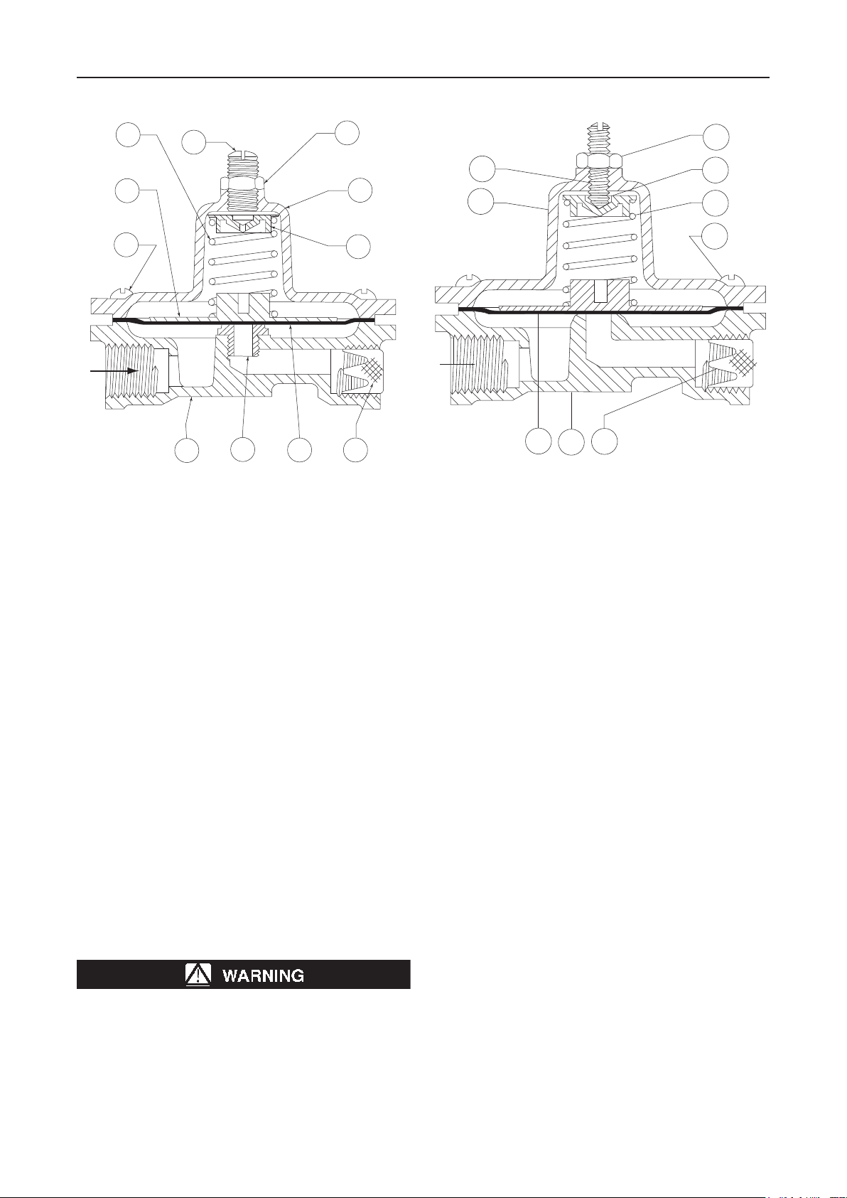
Figure 1. Type 289A Backpressure Regulator
1
10
5
11
11
6
4
2
2
4
9
18A2816-A
Figure 2. Type 289U Backpressure Regulator
5
9
1
7
8
For installation of Types 289H, 289HH, and 289L backpressure
regulators, the vent in the spring case must remain plugged or
undrilled in order for the pitot tube to function properly.
Overpressure
Maximum inlet pressures depend upon body materials and
temperatures. Refer to the nameplate for the maximum inlet
pressure of the valve. The valve should be inspected for damage
after any overpressure condition. Fisher® backpressure
regulators are NOT ASME safety relief valves.
Startup
The backpressure regulator is factory set at approximately the
midpoint of the spring range or the pressure requested, so an initial
adjustment may be required to give the desired results. With proper
installation completed and relief valves properly adjusted, slowly
open the upstream and downstream shutoff valves (if applicable).
Adjustment
To change the outlet pressure, remove closing cap or loosen the
locknut and turn the adjusting screw clockwise to increase outlet
pressure or counterclockwise to decrease pressure. Monitor the
outlet pressure with a test gauge during the adjustment. Replace
closing cap or tighten the locknut to maintain the desired setting.
Taking Out of Service (Shutdown)
To avoid personal injury resulting from sudden release
of pressure, isolate the backpressure regulator from
all pressure before attempting disassembly.
For the 2 NPT Type 289H backpressure regulators, when changing
from one spring range to another, it is recommended that a new
spring case be used so that the travel stop drive screw will be
positioned correctly for the corresponding spring range.
Parts List
Key Description
1 Valve Body
2 Spring Case/Spring Case Assembly
3 Diaphragm Head
4 Spring Seat
5 Diaphragm/Diaphragm Assembly
6 Adjusting Screw
7 Spring
8 Machine Screw
9 Screen
10 Orice
11 Hex Nut
13 Snap Ring
14 Closing Cap
15 Gasket
16 Nameplate
17 Lower Spring Seat
18 Pitot Tube
19 Gasket
20 O-Ring
21 O-Ring Holder
22 O-Ring Washer
23 Spacer
24 Hex Nut
25 Lifting Stem
26 Lower Diaphragm Head
27 Washer
28 Pipe Plug
29 Machine Screw
30 O-Ring
31 Stem Guide Assembly
38 Gasket
 Loading...