


3051S
Table of contents
 Loading...
www.rosemount.com
¢00825-0100-4801J¤
HART
®
Quick Installation Guide
00825-0100-4801, Rev HA
February 2008
Rosemount 3051S
Rosemount 3051S Series Pressure
Transmitter with HART
®
Protocol
Rosemount 3051SF Series Flowmeter
Transmitter with HART
®
Protocol
© 2008 Rosemount Inc. All rights reserved. All marks property of owner. Rosemount and the
Rosemount logotype are registered trademarks of Rosemount Inc.
Step 1: Mount the Transmitter
Step 2: Consider Housing Rotation
Step 3: Set Switches and Jumpers
Step 4: Connect Wiring and Power Up
Step 5: Verify Configuration
Step 6: Trim the Transmitter
Safety Instrumented Systems
Product Certifications
Start
End

Quick Installation Guide
00825-0100-4801, Rev HA
February 2008
Rosemount 3051S
2
Rosemount Inc.
8200 Market Boulevard
Chanhassen, MN USA 55317
T (US) (800) 999-9307
T (Intnl) (952) 906-8888
F (952) 949-7001
Emerson Process Management
GmbH & Co. OHG
Argelsrieder Feld 3
82234 Wessling
Germany
T 49 (8153) 9390, F49 (8153) 939172
Emerson Process Management
Asia Pacific Private Limited
1 Pandan Crescent
Singapore 128461
T (65) 6777 8211
F (65) 6777 0947/65 6777 0743
Beijing Rosemount Far East Instrument
Co., Limited
No. 6 North Street, Hepingli, Dong Cheng District
Beijing 100013, China
T (86) (10) 6428 2233
F (86) (10) 6422 8586
IMPORTANT NOTICE
This installation guide provides basic guidelines for Rosemount 3051S
transmitters (reference manual document number 00809-0100-4801). It
also provides the basic electronics guidelines for the 3051SFA
(reference manual document number 00809-0100-4809), 3051SFC
(reference manual document number 00809-0100-4810), and 3051SFP
(reference manual document number 00809-0100-4686). It does not
provide instructions for diagnostics, maintenance, service, or
troubleshooting. This document is also available electronically on
www.rosemount.com.

Quick Installation Guide
00825-0100-4801, Rev HA
February 2008
Rosemount 3051S
3
WARNING
Explosions could result in death or serious injury:
Installation of this transmitter in an explosive environment must be in
accordance with the appropriate local, national, and international
standards, codes, and practices. Please review the approvals section of
the 3051S reference manual for any restrictions associated with a safe
installation.
• Before connecting a HART communicator in an explosive
atmosphere, ensure the instruments in the loop are installed in
accordance with intrinsically safe or non-incendive field wiring
practices.
• In an Explosion-Proof/Flame-Proof installation, do not remove the
transmitter covers when power is applied to the unit.
Process leaks may cause harm or result in death.
• Install and tighten process connectors before applying pressure.
Electrical shock can result in death or serious injury.
• Avoid contact with the leads and terminals. High voltage that may be
present on leads can cause electrical shock.
Quick Installation Guide
00825-0100-4801, Rev HA
February 2008
Rosemount 3051S
4
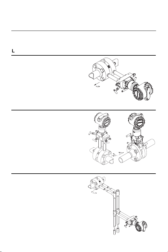
STEP 1: MOUNT THE TRANSMITTER
Liquid Flow Applications
1. Place taps to the side of the line.
2. Mount beside or below the taps.
3. Mount the transmitter so that the
drain/vent valves are oriented
upward.
Gas Flow Applications
1. Place taps in the top or side of
the line.
2. Mount beside or above the taps.
Steam Flow Applications
1. Place taps to the side of the line.
2. Mount beside or below the taps.
3. Fill impulse lines with water.
Quick Installation Guide
00825-0100-4801, Rev HA
February 2008
Rosemount 3051S
5
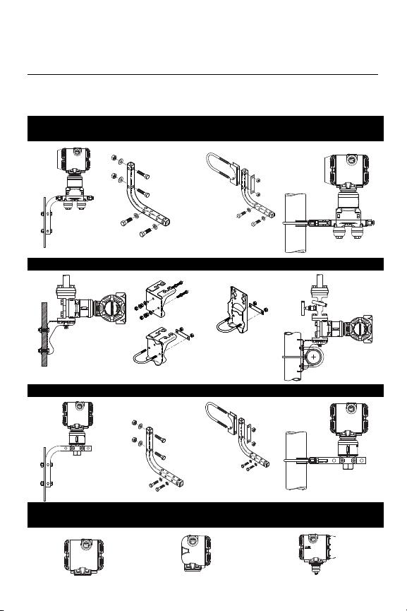
STEP 1 CONTINUED...
Panel Mount Pipe Mount
Coplanar
™
Flange
Traditional Flange
In-line
Housings
PlantWeb
™
Junction Box Remote Mount Display
Quick Installation Guide
00825-0100-4801, Rev HA
February 2008
Rosemount 3051S
6
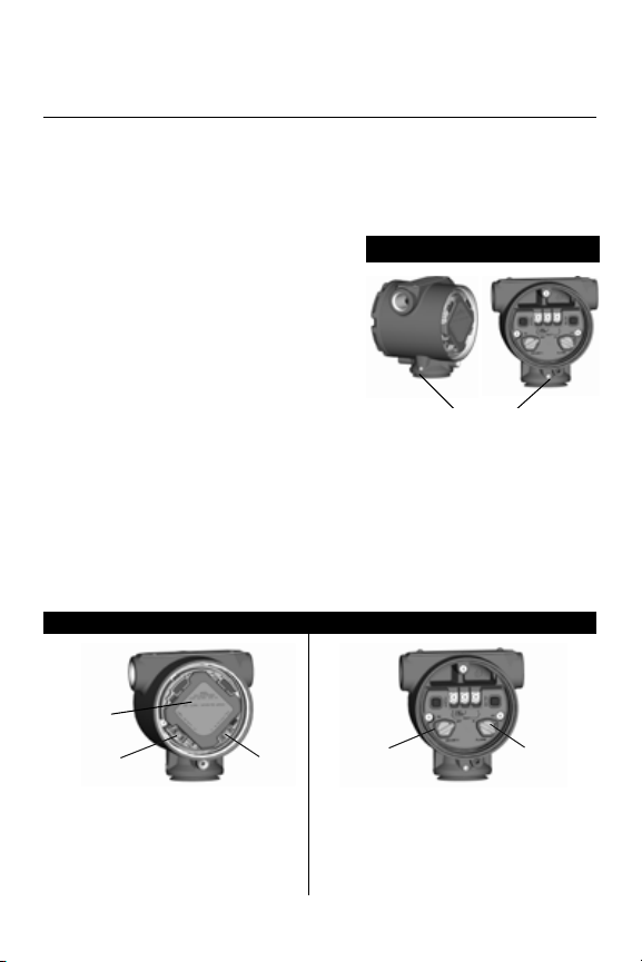
STEP 2: CONSIDER HOUSING ROTATION
STEP 3: SET SWITCHES AND JUMPERS
If alarm and security adjustment option is not installed, the transmitter
will operate normally with the default alarm condition alarm high and
the security off.
To improve field access to wiring or to
better view the optional LCD display:
Figure 1. Transmitter Housing
Set Screw
1. Loosen the housing rotation set
screw.
2. First rotate the housing clockwise
to the desired location. If the
desired location cannot be
achieved due to thread limit,
rotate the housing counter
clockwise to the desired location
(up to 360° from thread limit).
3. Retighten the housing rotation set
screw.
PlantWeb Junction Box
Figure 2. Transmitter Switch and Jumper Configuration
PlantWeb Junction Box
Slide the security and alarm
switches into the preferred position
by using a small screwdriver.
(A LCD display or an adjustment
module must be in place to activate
the switches.)
Pull the jumpers out and rotate 90°
into desired position to set the security
and alarm.
Housing Rotation Set
Screw (3/32-inch)
Alarm
Security
Meter/
Adjustment
Module
Security
Alarm
Quick Installation Guide
00825-0100-4801, Rev HA
February 2008
Rosemount 3051S
7
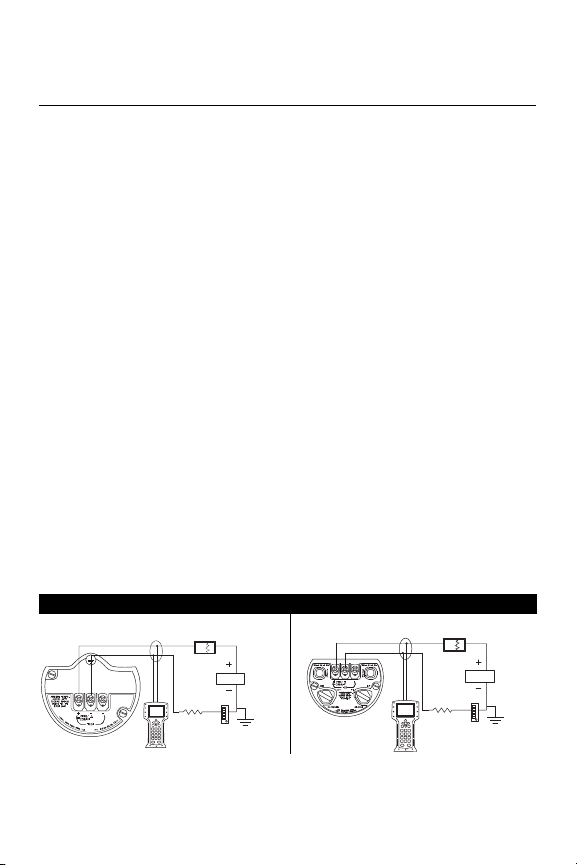
STEP 4: CONNECT WIRING AND POWER UP
Use the following steps to wire the transmitter:
1. Remove the housing cover labeled “Field Terminals.”
2. Connect the positive lead to the “+” terminal, and the negative lead
to the “–” terminal.
NOTE
Do not connect the power across the test terminals. Power could
damage the test diode in the test connection. Twisted pairs yield best
results. For single compartment housing (Junction Box housing),
shielded signal wiring should be used in high EMI/RFI environments.
Use 24 AWG to 14 AWG wire and do not exceed 5,000 feet
(1500 meters).
3. Plug and seal the unused conduit connection.
4. If applicable, install wiring with a drip loop. Arrange the drip loop
so the bottom is lower than the conduit connections and the
transmitter housing.
5. Replace the housing cover.
The figures below show the wiring connections necessary to power a
3051S and enable communications with a hand-held HART
communicator.
Figure 3. Transmitter Wiring
PlantWeb Housing Wiring Junction Box Housing Wiring
NOTE
Installation of the transient protection terminal block does not
provide transient protection unless the 3051S case is properly
grounded.
RL ≥ 250 Ω
Power
Supply
Power
Supply
RL ≥ 250 Ω

Quick Installation Guide
00825-0100-4801, Rev HA
February 2008
Rosemount 3051S
8
STEP 4 CONTINUED...
Remote Display Wiring and Power Up
The Remote Mount Display and Interface system consists of a local
transmitter and a remote mount LCD display assembly. The local
3051S transmitter assembly includes a Junction Box housing with a
three position terminal block integrally mounted to a SuperModule.
The remote mount LCD display assembly consists of a dual
compartment PlantWeb housing with a seven position terminal block.
See Figure 4 on page 9 for complete wiring instructions. The following
is a list of necessary information specific to the Remote Mount Display
system:
• Each terminal block is unique for the remote display system.
• A 316 SST housing adapter is permanently secured to the remote
mount LCD display PlantWeb housing providing an external
ground and a means for field mounting with the provided mounting
bracket.
• A cable is required for wiring between the transmitter and remote
mount LCD display. The cable length is limited to 100 ft.
• 50 ft. (option M8) or 100 ft. (option M9) cable is provided for wiring
between the transmitter and remote mount LCD display. Option
M7 does not include cable; see recommended specifications
below:
Cable type: Recommend Belden 3084A DeviceNet cable or Belden
123084A Armored DeviceNet cable. Other comparable cable may be
used as long as it has independent dual twisted shielded pair wires
with an outer shield. The Power wires must be 22 AWG minimum and
the CAN communication wires must be 24 AWG minimum.
Cable length: Up to 100 feet depending upon cable capacitance.
Cable capacitance: The capacitance from the CAN communications
line to the CAN return line as wired must be less than 5000 picofarads
total. This allows up to 50 picofarads per foot for a 100 foot cable.
Quick Installation Guide
00825-0100-4801, Rev HA
February 2008
Rosemount 3051S
9
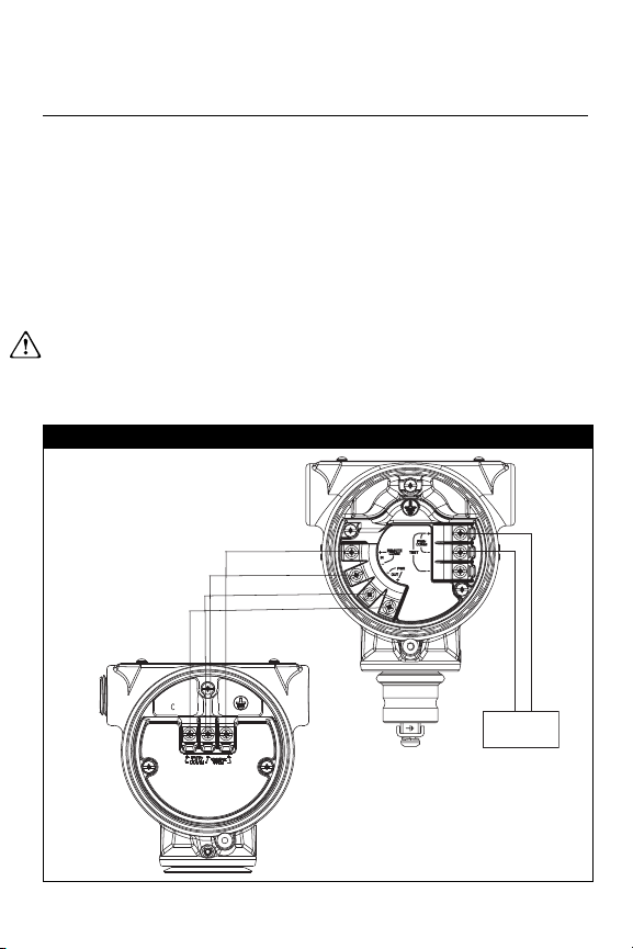
STEP 4 CONTINUED...
Intrinsic Safety Consideration: The transmitter assembly with
remote display has been approved with Belden 3084A DeviceNet
cable. Alternate cable may be used as long as the transmitter with
remote display and cable is configured according to the installation
control drawing or certificate. Refer to appropriate approval certificate
or control drawing in Appendix B of the 3051S reference manual for
remote cable IS requirements.
IMPORTANT
Do not apply power to the remote communications terminal. Follow
wiring instructions carefully to prevent damage to system components.
Figure 4. Remote Mount Display wiring diagram
Junction Box Housing Remote Mount Display
4-20 mA
(white) 24 AWG
(blue) 24 AWG
(black) 22 AWG
(red) 22 AWG
Quick Installation Guide
00825-0100-4801, Rev HA
February 2008
Rosemount 3051S
10
STEP 4 CONTINUED...
NOTE
Wire colors provided on page 9 are per Belden 3084A DeviceNet
cable. Wire color may vary depending on cable selected.
Belden 3084A DeviceNet cable includes a ground shield. This shield
must be connected to earth ground at either the SuperModule or the
Remote Display, but not both.
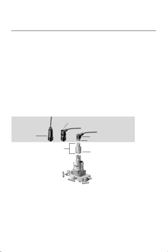
Quick Connect Wiring
As standard, the 3051S Quick Connect arrives properly assembled to
the SuperModule and is ready for installation. Cordsets and Field
Wireable Connectors (in shaded area) are sold separately.
Figure 5. Rosemount 3051S Quick Connect Exploded View
IMPORTANT
If Quick Connect is ordered as a 300S spare housing or is removed
from the SuperModule, follow the instructions below for proper
assembly prior to field wiring.
1. Place the Quick Connect onto the SuperModule. To ensure proper
pin alignment, remove coupling nut prior to installing quick connect
onto SuperModule.
Straight Field
Wireable
Connector
(1)(3)
Right Angle Field Wireable
Connector
(2)(3)
Coupling Nut
Cordset
(4)
Quick Connect
Housing
Quick Connect Coupling Nut
(1) Order part number
03151-9063-0001.
(2) Order part number
03151-9063-0002.
(3) Field wiring supplied by customer.
(4) Supplied by cordset vendor.

Quick Installation Guide
00825-0100-4801, Rev HA
February 2008
Rosemount 3051S
11
STEP 4 CONTINUED...
2. Place coupling nut over quick connect and wrench tighten to a
maximum of 300 in-lb. (34 N-m).
3. Tighten the set screw using a
3
/32-in hex wrench.
4. Install Cordset/ Field Wireable Connectors onto the Quick Connect.
Do not over tighten.
Figure 6. Quick Connect Housing Pin-Out
Conduit Electrical Connector Wiring (Option GE or GM)
For 3051S transmitters with conduit electrical connectors GE or GM,
refer to the cordset manufacturer’s installation instructions for wiring
details. For FM Intrinsically Safe, non-incendive or FM FISCO
Intrinsically Safe hazardous locations, install in accordance with
Rosemount drawing 03151-1009 to maintain outdoor rating (NEMA 4X
and IP66.) See Appendix B of the 3051S reference manual.
For other wiring
details, refer to pin-out
drawing and the
cordset
manufacturer’s
installation
instructions.
“+”
“–”
Ground
No Connection
Loading...