


|
|
|
|
|
|
|
|
|
|
|
|
|
|
|
|
|
|
|
|
|
|
|
|
|
|
|
|
|
|
|
|
|
|
|
|
|
|
|
|
|
|
|
|
|
|
|
|
|
|
|
|
|
|
|
|
|
|
|
|
|
|
|
|
|
|
|
|
RDS |
|
|
|
|
USB |
DVD |
iPOD |
A/V Input |
|
|
|
|
|
|
|
|
||||||
|
|
|
|
|
|
|
||||||
|
|
|
|
|
SD |
|||||||
|
|
|
|
|
||||||||
DivX MP3 WMA DVD |
VCD |
CD |
CD-R CD-RW ID3 |
RDS |
|
|
|
|
|
|
|
|
|
|
|
|
|
|
|
|
|
|
|
|

Welcome!
Dear Customer,
CONGRATULATIONS. The VRVD640G DVD/CD Player and AM/FM Stereo Receiver with RDS, SD Card, USB Port and AUX In, when used as described, will give you years of dependable service in your car, truck, RV, or mini-van. We have taken numerous measures in quality control to ensure that your product arrives in top condition and will perform to your satisfaction. In the rare event that your VRVD640G DVD/CD Player and AM/FM Stereo Receiver with RDS, SD Card, USB Port and AUX In contains a damaged or missing item, does not perform as specified, requires warranty service, or you have an installation problem, DO NOT RETURN THIS PRODUCT TO THE STORE. PLEASE CALL OUR TOLL FREE NUMBER FROM THE U.S.A. AND CANADA 1-800- 445-1797 and ask to speak with a member of our technical service team; or submit your questions by e-mail to customerservice@vr-3.com and a member of our technical service team will respond by e-mail to your questions. Our in-house technical service team will expedite delivery of your part, advise you on installation, or help troubleshoot a problem with you. If your product needs warranty service, our technical service team representative will help you obtain the fastest remedy possible under the warranty.
TABLE OF CONTENTS |
|
Contents....................................................................................................................... |
2-3 |
Warnings ......................................................................................................................... |
4 |
Precautions ..................................................................................................................... |
5 |
Disc & Memory Types..................................................................................................... |
6 |
Care of Discs................................................................................................................... |
6 |
Remove the Old Unit....................................................................................................... |
7 |
Installation (DIN Front Mount) ....................................................................................... |
7 |
Installation (Vehicle's Brackets)...................................................................................... |
9 |
Parts ............................................................................................................................................... |
9 |
Wiring Connections ...................................................................................................... |
10 |
Location of the Controls............................................................................................... |
11 |
Main Menu..................................................................................................................... |
16 |
Menu Screens ........................................................................................................... |
17-18 |
Radio Operation....................................................................................................... |
19-20 |
Multimedia Operation .............................................................................................. |
21-23 |
Navigation System |
|
Operating Controls .................................................................................................. |
24-26 |
Main Menu..................................................................................................................... |
26 |
GPS Data Screen.......................................................................................................... |
26 |
GPS Data Display ......................................................................................................... |
26 |
GPS Connection Indicator............................................................................................ |
27 |
GPS Connection Quality Indicator............................................................................... |
27 |
Time Synchronization ................................................................................................... |
27 |
The Map ........................................................................................................................ |
27 |
Map Controls & Functions....................................................................................... |
27-31 |
Cockpit Screen ............................................................................................................. |
32 |
Turn Preview ................................................................................................................. |
32 |
Zoom In And Out .......................................................................................................... |
32 |
Next Street / Next City ................................................................................................. |
32 |
Map Orientation And Overview .................................................................................... |
32 |
GPS Position Quality .................................................................................................... |
33 |
Sound Muting................................................................................................................ |
33 |
Track Log Recording/Playback Indicator..................................................................... |
33 |
Cursor............................................................................................................................ |
33 |
Lock To GPS Position And Heading ...................................................................... |
33-34 |
Cusor Menu............................................................................................................. |
34-35 |
Current Street ............................................................................................................... |
35 |
Tilt Up And Down.......................................................................................................... |
35 |
Menu.............................................................................................................................. |
35 |
Travel and Route Data .................................................................................................. |
35 |
Distance to Next Turn ................................................................................................... |
36 |
Approaching Next Turn................................................................................................. |
36 |
Map Scale ..................................................................................................................... |
36 |
Route Information Screen............................................................................................. |
36 |
Route Data Displayed ................................................................................................... |
36 |
2

Contents
Route Line ................................................... |
36 |
Distance Left ............................................... |
37 |
Method ........................................................ |
37 |
Time Left...................................................... |
37 |
Estimated Arrival ......................................... |
37 |
Destination / Via Point ................................ |
37 |
Warning Icons ........................................ |
37-38 |
Fit To Screen ............................................... |
38 |
Parameters .................................................. |
38 |
Menu Button................................................ |
38 |
Find Tab....................................................... |
38 |
Quick Tab .................................................... |
38 |
Route Tab .................................................... |
38 |
3D Map (switch)........................................... |
38 |
Zoom & Tilt (switch)..................................... |
38 |
Night Mode (switch) .................................... |
38 |
Manage POI (Points of Interest).................. |
39 |
Manage Built-In POI Visibility ..................... |
39 |
Manage My POI..................................... |
39-40 |
Manage Track Logs ................................... |
40 |
Route Tab ................................................... |
41 |
Recalculate.................................................. |
41 |
Drop Next Via Point / Delete Route............ |
41 |
Bypass......................................................... |
41 |
Cancel.......................................................... |
41 |
Delete .................................................... |
41-42 |
Display Modes............................................. |
42 |
Show............................................................ |
42 |
Avoid............................................................ |
42 |
Fly Over ....................................................... |
42 |
Lifelike Simulation ...................................... |
42 |
Edit .............................................................. |
43 |
Info .............................................................. |
43 |
Main Button................................................. |
43 |
SETTINGS ................................................... |
43 |
General Settings ......................................... |
43 |
Safety Mode ................................................ |
43 |
Set Favorite Destinations ..................... |
43-44 |
Automatic Night Colors .............................. |
44 |
Speeding Tolerance .................................... |
44 |
Alternative Speed Limit............................... |
44 |
Alternative Speeding Tolerance.................. |
44 |
Route Recalculation.................................... |
44 |
Automatic .................................................... |
44 |
Ask First ................................................ |
44-45 |
Disabled....................................................... |
45 |
MAP SETTINGS .......................................... |
45 |
Daylight / Night Color Profile ...................... |
45 |
Cockpit / Map Mode Map Details .............. |
45 |
Alternative Road Names ............................. |
45 |
Show Street Labels..................................... |
45 |
Textured Polygons ...................................... |
46 |
SOUND SETTINGS ..................................... |
46 |
Master Sound Volume/Switch .................... |
46 |
Voice Guidance Volume/Switch ................. |
46 |
Key Sound Volume/Switch ......................... |
46 |
Dynamic Volume ......................................... |
46 |
Attention Tone ............................................ |
46 |
ROUTE PARAMETER SETTINGS............... |
47 |
Method ........................................................ |
47 |
Route ........................................................... |
47 |
Short ............................................................ |
47 |
Fast .............................................................. |
47 |
Economical.................................................. |
47 |
Vehicle ......................................................... |
47 |
Road Types to Include/Exclude.................. |
|
47 |
Unpaved Roads........................................... |
|
48 |
Motorways................................................... |
|
48 |
Ferries.......................................................... |
|
48 |
U-Turns ........................................................ |
|
48 |
Permit Needed ............................................ |
|
48 |
Toll Roads.................................................... |
|
48 |
LANGUAGE & UNITS .................................. |
|
48 |
Program Language ..................................... |
|
48 |
Voice Language........................................... |
|
48 |
Units............................................................. |
|
48 |
Set Date & Time Format.............................. |
|
48 |
ADVANCED SETTINGS............................... |
|
49 |
Display Options........................................... |
|
49 |
2D in Map mode (and North-up orientation) ..... |
49 |
|
3D in Cockpit mode ................................... |
|
49 |
Zoom In After Find ..................................... |
|
49 |
Coordinate Display Format ........................ |
|
49 |
Cockpit Screen Layout ............................... |
|
50 |
BACKLIGHT SETTINGS.............................. |
|
50 |
Power Management .................................... |
|
50 |
Backlight Always On ................................... |
|
50 |
Brightness ................................................... |
|
50 |
SMART ZOOM SETTINGS.......................... |
|
50 |
Enable Overview Mode............................... |
|
50 |
Restore Lock-to-position And Smart Zoom...... |
|
50 |
Restore Lock-to-Position............................ |
|
51 |
Restore Smart Zoom .................................. |
|
51 |
Delay Before Restoring............................... |
|
51 |
ROUTE OPTIONS........................................ |
|
51 |
Off-Route Sensitivity And Recalculation Delay.51 |
||
Off-route Sensitivity .................................... |
|
52 |
Recalculation Delay .................................... |
|
52 |
U-Turn Penalty............................................. |
|
52 |
Cross-Border Planning ............................... |
|
52 |
Keep Position On Road (Lock-on-Road) ... |
52 |
|
USER DATA MANAGEMENT....................... |
|
52 |
Backup Data................................................ |
|
53 |
Restore Data ............................................... |
|
53 |
Remove Pins ............................................... |
|
53 |
Clear Data.................................................... |
|
53 |
Reset Advanced Settings ........................... |
|
53 |
FIND & GO (Main Menu) ............................. |
|
53 |
Selection By Tapping The Map .................. |
|
53 |
USING THE FIND MENU............................. |
|
54 |
Find An Address, Street, Intersection Or City... |
54 |
|
Selecting the City, State or Country to Search in ....... |
|
54 |
Selecting A New City To Search In ............ |
|
54 |
Changing the State (Australia, USA, etc.) .. |
55 |
|
Changing The Country................................ |
|
56 |
Selecting A Street Or The Center Of The City .. |
56 |
|
Selecting The Center Of The City .............. |
|
56 |
Selecting A Street ....................................... |
|
56 |
Selecting A House Number Or The Midpoint Of The Street.... |
56 |
|
Select An Intersection Instead Of A House Number ... |
56 |
|
An Example For A Full Address Search ..... |
57 |
|
Find in History ............................................. |
|
57 |
Find Coordinates......................................... |
|
57 |
Find a POI.................................................... |
|
58 |
Find one of the Favourites (Home/Work) ... |
59 |
|
Frequently Asked Questions ................ |
60-61 |
|
Glossary ................................................ |
61-63 |
|
Specifications........................................ |
64-65 |
|
NOTES ......................................................... |
|
66 |
Limited Warranty......................................... |
|
67 |
3

Warnings
•For safety reasons, certain video functions are disabled unless the parking brake is on. The Unit is designed with circuitry to detect the parked status of the vehicle, and must be connected to the power supply side of the parking brake switch. Improper connection or use of this connection may violate applicable law and may result in serious injury or damage.
•To avoid any risk of damage to the vehicle or injury its occupants and the potential violation of applicable laws, this unit is not for use with a video screen that is visible to the driver.
•Disconnect negative battery terminal before starting installation. Failure to disconnect the negative battery cable may cause damage to the unit or the vehicle’s electrical system. Consult the vehicle’s owner’s manual for proper instruction.
•Before final installation of the unit, temporarily connect the wiring, to make sure the unit works properly.
•Use only the parts included with this unit to ensure proper installation. The use of unauthorized parts may cause damage to the vehicle or unit.
•If installation requires the drilling of holes or other modifications to the vehicle, consult with your vehicle’s nearest dealership.
•Install the unit in a location where it shall not obstruct driver’s ability to safely operate the vehicle, and cannot injure any passengers if there is a sudden stop, like an emergency stop.
•The laser will be damaged if it overheats, do not install the unit where it will be exposed to excessive heat -- for instance, near a heater outlet.
•For optimum performance, do not install more than 30 degrees from horizontal.
4

PRECAUTIONS
Driving a vehicle while viewing a video on this head unit may violate motor vehicle laws, and may result in serious injury, property damage, or death!
Please read these important precautions BEFORE attempting to install this unit.
•Disconnect the vehicle’s negative battery terminal before starting installation. Consult the vehicle’s owner’s manual for proper instruction.
•The unit is designed for a 12 Volt DC negative ground operation system only. Before installing the unit, make sure your vehicle is a 12Volt DC negative ground system.
•Mark the polarity of the existing speaker wires before disconnecting the old head unit.
•Be sure to connect the color coded leads according to the wiring diagram. Incorrect connections may damage the unit or cause the unit to malfunction or cause damage the vehicle's electrical system.
•Make sure all the connections are completely correct before turning on your unit.
•When extending the ignition, memory backup or the ground cable, use 0.75mm diameter (AWG18) or heavier automotive grade cable to avoid wire deterioration or damage to the wire coating.
•To prevent short circuit, never put or leave any metallic object inside the unit. If you smell or see smoke, turn off the power immediately and consult your dealer.
•Insert the unit until it is firmly locked into mounting sleeve, otherwise it may fall out.
•Be careful not to drop or shock the unit, it may break or crack because it contains glass parts.
•The unit is only designed for use with 4 speakers. Do not combine speaker output wires for use with 2 speakers. Do not ground negative speaker leads to the chassis ground.
•Do not open the top or bottom cover. Modifying the unit will void the warranty and may damage the unit or cause the unit to malfunction or cause damage the vehicle's electrical system.
•Parking in direct sunlight for several hours will cause higher temperatures inside the vehicle. Do not operate in extremely high or low temperatures. The temperature inside the vehicle should be between 32º F (0º C) and 100º F (37º C) before turning on your unit. Cool down the vehicle before operating the unit
•The faceplate is a precision piece of equipment that contains sensitive electronic components. Do not subject it to excessive shock.
•When replacing the fuse(s), the replacement must be of the same amperage as shown on the fuse holder.
•Do not block this unit’s vents or heater panels. Blocking them will cause excessive heat to build up inside the unit and may result in fire.
•After completing the installation and before operating the unit, reconnect the battery according to the manufacturer’s instructions. Then press the reset (RES) button with a pointed object, such as a ball-point pen to set the unit to its initial status.
•Do not touch the terminals of the faceplate or of the unit.
•If you have difficulty installing this unit in your vehicle contact customerservice@ vr-3.com or Call 1-800-445-1797
5

Disc & Memory Types
• This unit will only play the following discs or memory types.
Disc Type |
Icon |
Content |
Size |
Playtime |
DVD |
|
Audio/Video |
12cm |
About 2 - 4.5 Hours |
VCD |
|
Audio/Video |
12cm |
About 74 minutes |
CD |
|
Audio |
12cm |
About 74 minutes |
MP3 |
|
Audio |
12cm |
About 600 minutes |
MPEG4 |
|
Audio/Video |
12cm |
|
DIVX |
|
|
|
|
Memory Type |
Icon |
Content |
Size |
Playtime |
||
USB Flash Memory |
|
|
|
Audio/Video |
Up to 2 Gb |
Depends on size of files |
|
|
|
||||
|
|
|
|
|
|
|
SD Card |
|
|
|
Audio/Video |
Up to 2 Gb |
Depends on size of files |
|
|
|
|
|
|
|
MMC |
|
|
|
Audio/Video |
Up to 2 Gb |
Depends on size of files |
|
|
|
|
|
|
|
Care of Discs
•Handle the disc by its edge to keep the disc clean. Do not touch the disc’s surface.
•Do not use a CD with paste or ink residue on it.
•Do not attempt to modify the unit.
•Modifying the unit will void the warranty.
•Stop the vehicle before carrying out any operation that could interfere with your driving.
•Do not operate in extremely high or low
•Do not use CDs with labels or stickers attached. The label may leave a sticky residue when it begins to peel.
•Clean the discs with an optional cleaning cloth. Wipe each disc from the center out.
temperatures. The temperature inside the vehicle should be between 32º F (0º C) and 100º F (37º C) before turning on your unit.
6

Installation
Automotive audio equipment installations can be challenging at times, even to the most experienced of installation technicians. If you are not confident working with electrical wiring, removing and reinstalling interior panels, carpeting, dashboards or other components of your vehicle, please e-mail us at customerservice@vr3.com or call our Toll-Free help line 1-800-445-1797 and our in-house technical service team will answer your installation questions. Or consider having the VRVD640G professionally installed. Contact the vehicle's manufacturer for vehicle specific instructions,
1. Remove the Old Unit from the Dashboard
A. Remove the outer trim frame. |
B. Insert the keys supplied with the old unit |
|
into both sides of the unit as shown in |
|
figure below until they click. Pull to re- |
|
move the old unit from the dashboard. |
DIN Front Mount
DO NOT DISCONNECT WIRES AT THIS TIME!
2. Mark Polarity of the Speaker Wires
Marking the polarity of the speaker wires will make it easier to connect the existing speakers to the VRVD640G. Consult the wiring diagram of the existing head unit before disconnecting any wires. If a wiring diagram is not available contact the head unit’s manufacturer.
1.While the old unit is playing, disconnect the wires from one speaker.
2.Take a length of masking tape and fold it around the wire so it forms a flag.
3.On the masking tape mark the polarity of the speaker wires (+ & - ), as well as left or right, and front or rear.
4.Double check that you marked the first speaker correctly by checking that the speaker wires are the same at the head unit.
5.Repeat this procedure for all of the speakers.
6.Mark the power, ground, and any other wires also.
GIVE US A CALL, WE'LL HELP YOU INSTALL.
PLEASE DO NOT RETURN PRODUCT TO STORE.
Visit us on the WEB
www.vr-3.com
For Information and Technical Assistance, Call Toll-Free in U.S.A. and Canada.
1-800-445-1797
7

Installation
DIN FRONT-MOUNT (Method A)
IMPORTANT!
BEFORE THE FINAL INSTALLATION OF THE HEAD UNIT, CONNECT THE WIRING TEMPORARILY, MAKING SURE THE UNIT AND THE SYSTEM WORK PROPERLY.
Insert fingers into the groove in the front of frame to remove it.
Insert the keys supplied with the old unit into the grooves on both sides of the old unit. The unit can be installed or removed from the dashboard using these keys. (Fig. 1)
Remove the half sleeve
Fig. 1


 After inserting the Mounting Sleeve into the


 dashboard, select tabs on top, bottom,


 and
and sides, then bend them to secure the


 mounting sleeve in the dash board.(Fig. 2)
Fig. 2
Follow the diagram in Fig. 3 for installing the rear mounting strap to the head unit. The rear mounting strap will help keep the head unit from moving around inside the dashboard.
1.Dashboard
2.Nut (5mm)
3.Spring washer
4.Screw (5 x 25mm)
5.Screw
6.Strap
7.Plain washer
Fig. 3
8

Installation
DIN REAR-MOUNT (Method B)
Installation using the screw holes on both sides of the unit.
1. Screw holes on the side of the unit.
2. Screws. Use either truss screws (5 x 8mm) or flush surface screws (4 x 8mm), depending on the shape of the screw holes in the bracket.
3. Vehicle’s Factory Mounting Bracket
4. Dashboard or Console
5. Hook (Remove this part)
NOTE: The mounting sleeve, outer trim ring, and the mounting strap are not used for this method of installation.
PARTS
Check All Included Parts
Open the VRVD640G box and remove all parts, then check all parts and compare them to the parts list in the user manual. For replacement parts contact VR3 Customer Service at customerservice@vr-3.com or call 1-800-445-1797.
2 Keys
1 Mounting Sleeve*
1 Sheet Metal Screw
1 Metal Support Strap
1 Mounting Bolt
1 Faceplate Case
1 1/8" Audio/Video Cable
1 AV Input Adaptor & Bracket*
1 Remote Control*
*=Not Shown
9
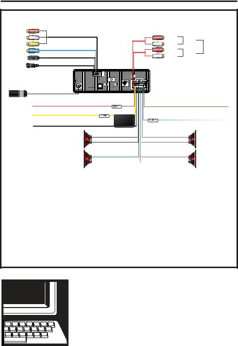
Wiring Connections
VRVD640G
DVD Out
Subwoofer Out
GPS Antenna
3.5mm Female A/V IN
Radio Antenna
IGNITION |
RED (+) |
MEMORY |
YELLOW (+) |
Connect YELLOW to battery or live 12 V(+)
Negative Ground -
12 Volt Negative -
Front Left
Rear Left
1 AMP
15 AMP
FILTER
WHITE +
WHITE/BLACK -
GREEN +
GREEN/BLACK -
Right |
Rear |
|
Left |
||
RCA Line Out |
||
Right |
||
Front |
||
Left |
||
|
DRIVER SAFETY WIRE
BROWN (-) PARKING BRAKE
1 AMP BLUE (+) POWER ANTENNA OR AMPLIFIER
GRAY + |
Front Right |
|
|
GRAY/BLACK - |
|
VIOLET + |
Rear Right |
|
|
VIOLET/BLACK - |
|
DRIVER SAFETY WIRE, MUST be connected to the car’s parking break switch-wire. Virtual Reality Video Labs and/or its affiliates waves any and all liability when this wire is NOT connected as directed. Driver can only watch a movie when the parking brake is ON.
•Before starting the installation, disconnect the negative battery cable from the battery’s negative terminal.
•Before final installation of the unit, connect the wiring temporarily, making sure the unit and the system operates properly.
GIVE US A CALL, WE'LL HELP YOU INSTALL.
PLEASE DO NOT RETURN PRODUCT TO STORE.
Visit us on the WEB
www.vr-3.com
For Information and Technical Assistance, Call Toll-Free in U.S.A. and Canada.
1-800-445-1797
10
Location Of The Controls
8 10 12 14
1 |
2 3 4 |
5 6 |
7 |
9 |
11 |
13 |
15 |
|||
|
|
|
|
|
|
|
|
|
|
|
|
|
|
|
|
|
|
|
|
|
|
|
|
|
|
|
|
|
|
|
|
|
IR |
POWER |
OPEN |
|
MUTE |
|
|
VOL+ |
1 |
2 |
TUN- |
OK |
MODE |
|
TUN+ |
|
||
|
|
||
|
VOL- |
3 |
4 |
|
|
|
|
|
|
MENU |
STOP |
PTY |
|
5 |
6 |
|
|
BAND |
|
|
|
FUNC |
|
TA |
|
|
|
GPS NAVIGATION & DVD PLAYER
CD, CD-R, CD-RW, VCD, DIVX, MP3, WMA
|
23 |
22 |
21 |
|
20 |
18 |
16 |
|
|
|
|
|
19 |
|
17 |
1. |
Left Arrow/Channel Down |
13. |
#4 Button/Stop |
|
|
||
2. |
Eject |
|
|
14. |
Open |
|
|
3. |
OK |
|
|
15. |
#2 Button/Step Forward |
|
|
4. |
Up Arrow/Volume Up |
16. |
#6 Button/Fast Forward |
|
|
||
5. |
Right Arrow/Channel Up |
17. USB Cover & Slot |
|
|
|||
6. |
Down Arrow/Volume Down |
18. |
#3 Button/Play/Pause |
|
|
||
7. |
TFT LCD Screen |
19. #5 Button/ Fast Reverse |
|
|
|||
8. |
Menu |
|
|
20. Band |
|
|
|
9. |
Mode |
|
|
21. FUNC Button |
|
|
|
10. |
Infra Red Window |
22. PTY Button |
|
|
|||
11. |
#1 Button/Step Backward |
23. TA |
|
|
|||
12. Power/Mute
Audio/Video Auxiliary Input
The VRVD640G is equipped with an Audio/ Video Auxiliary Input cable and mounting bracket.
In order to use the Audio/Video Auxiliary Input you MUST use the mounting bracket. Insert Audio/Video Auxiliary Input cable from the rear of the VRVD640G into the mounting bracket, then twist to lock.
The Adaptor has two 3.5 mm jacks (one Yellow for Video and one Black for Stereo Audio).
The Yellow jack on the Adpator accepts
a 3.5 mm mono Video plug from devices like portable DVD players and Video game controllers.
The Black jack on the Adaptor accepts a Stereo Audio 3.5 mm plug from any Stereo Audio device (CD player, MP3 player, DVD, etc).
UNLOCK LOCK
11

Remote Control
1 |
POWER |
|
|
|
|
DUAL |
TILT |
OPEN |
|
2 |
|
|
|
|
3 |
EJECT |
OSD |
MODE |
MUTE |
4 |
|
|
|
|
5 |
SETUP |
|
MENU |
|
|
|
|
|
|
6 |
|
|
|
|
7 |
|
|
|
|
8 |
ANGLE |
|
|
INT |
9 |
|
|
|
PBC |
SEL |
VOL - |
VOL + |
|
|
10 |
|
GO TO |
|
ZOOM |
|
|
|
||
|
|
|
|
|
11 |
FUNC |
AUDIO |
SUB-T |
A-B |
RDM |
PROG |
RPT |
|
|
12 |
|
|||
BAND |
PTY |
P.SCN |
TA |
|
13 |
1 |
2 |
3 |
4 |
14 |
5 |
6 |
7 |
8 |
|
||||
90
|
1. POWER |
14. PTY/PROG |
|
|
2. DUAL |
15. OPEN |
|
15 |
3. EJECT |
16. TILT |
|
4. OSD |
17. MUTE |
||
16 |
5. SETUP |
18. MODE |
|
17 |
6. UP/DOWN/LEFT/ |
19. MENU |
|
18 |
RIGHT/ENTER |
20. NEXT TRACK/ |
|
7. PREVIOUS |
FAST FORWARD |
||
19 |
|||
TRACK/FAST RE- |
21. INT |
||
|
|||
|
VERSE |
22. PLAY/PAUSE |
|
20 |
8. ANGLE |
23. STOP/PBC |
|
9. SEL |
24. VOLUME UP |
||
|
|||
21 |
10. VOLUME |
25. A-B/ZOOM |
|
DOWN |
26. SUB-T |
||
22 |
11. FUNC |
27. TA |
|
23 |
12. AUDIO/GO TO |
28. P.SCN/RPT |
|
24 |
|||
13. BAND/RDM |
29. 0-9 BUTTONS |
||
25 |
|||
|
|
||
26 |
|
|
|
27 |
See page 8 for a detailed description of the button’s functions. |
||
28 |
Changing the Battery |
||
|
|||
29 |
|
Turn the remote |
|
|
|
over, then slide the |
|
|
|
battery holder out |
|
|
|
of the remote. |
|
Use and Care of the Remote
Point the remote control at the front panel of the unit to operate.
Precautions:
•Using batteries improperly can cause them to explode.
•Keep the battery out of the reach of children.
•Should the battery be swallowed, immediately consult a doctor.
•Use one CR2025(3V) lithium battery.
•Remove the battery if the remote control is not to be used for a month or longer.
•Do not short-circuit or disassemble
•Dispose of spent batteries properly.
•Do not drop the remote control, it may become jammed under the brake or accelerator pedals.
Insert battery into battery holder with positive side of the battery facing up.
Insert battery holder into the remote control until
Dispose of All Batteries Properly
12

Remote Control
1. POWER
Press to turn the unit ON or OFF.
2. DUAL (DVD Output)
During DVD Mode this button toggles the Display settings under Settings II.
3. EJECT
During DVD Mode Press the EJECT button to eject the disc in the unit.
4. OSD
In radio mode only, press the OSD button to toggle between Radio frequency and Time display.
5. SETUP
In playback mode, press to access the setup menus for Language, Display, Audio, and Parental.
6. TRIANGLE BUTTONS [ /
/  /
/ /
/ ]
]
Use the Triangle buttons to navigate File lists and the setup menus.
7. SKIP BACKWARDS/FAST REV.
Press the button to go to the previous track, photo, or video. Press and hold this button to play a video in reverse at 2x current speed.
8. ANGLE
Press to change the viewing angle in DVD mode. Only if DVD Supports.
9. SEL
Press to confirm your choice on the menus.
10. VOLUME DOWN
Press to decrease the volume.
11. FUNC
Press to access the navigation system, press again to return to previous mode.
12. AUDIO/GO TO
In DVD mode, press to display current audio configuration.
13. BAND/RDM
In Radio mode, Change radio band in sequence of FM1 > FM2 > FM3 > AM1 > AM2.
14. PTY/PROG
In radio mode PTY will allow a search of radio program types. In VCD/CD mode, press the AMS button to program the order you wish the chapters to be played.
15. OPEN
Press to open the faceplate.
16. TILT
Press to adjust the angle of the faceplate for better viewing.
17. MUTE
Press to shut off the sound output. Press it again to resume previous sound level.
18. MODE
Press the MODE button to change the operating mode of the unit.
19. MENU
Press to access the Main menu anytime.
20.SKIP FORWARD/FAST FORWARD
Press the 
 button to go to the next track, photo, or video. Press and hold this button to play a video in at 2x current speed.
21.INT
Press to play the first 10 seconds of tracks on a disc, SD card, or USB memory.
22. PLAY/PAUSE
Press to play or resume the current playback.
23. STOP/PBC
Press to stop the playback. Press to display menus on VCD discs.
PBC ON songs play in order.
PBC OFF songs can be played in any order you wish.
24. VOLUME UP
Press to increase the volume.
25. A-B/ZOOM
In disc mode, A-B mode enables you to repeat a section of the disc. Press once, it sets the “A” position (beginning of the loop); pressed a 2nd time, it sets the “B” position (end of the loop). Pressed again, it exits the loop.
Zoom-Press to increase or decrease the picture in size.
26. SUB-T
In DVD playback mode, press to change the subtitle language.
27. TA
In radio mode allows reception of Traffic Announcements.
28. P.SCN/RPT
In Radio mode press to scan and save strongest staions to pre-set buttons.
In DVD mode, press to repeat tracks.
29. 0-9 BUTTONS/ENTER
Use number buttons to choose track numbers. Enter Confirms choices on menu.
13

Basic Operations
Driving a vehicle while viewing a video on this head unit may violate motor vehicle laws, and may result in serious injury, property damage, or death!
To play a video the vehcle must be stopped and the parking brake must be engaged.
Install the face Plate
1)Fit the face plate with its left hole on the left pin provided on the main unit.
2)Fit the other hole on the other pin applying slight pressure
3)Move the face plate up and down a few times to make sure it is secure. Then close the face plate and press down the right side of the face plate until it clicks into plate.
Caution
• This face plate is not waterproof. Do not expose it to water or excessive moisture,
• Do not remove the face plate while driving your car.
• Do not place the face plate on the dashboard or nearby areas where the temperature rises high.
• Do not touch the contacts on the face plate and the main unit, since this may result poor electrical contact.
• If dirt or other foreign substances get on the contacts, wipe them off with a clean and dry cloth.
• To avoid damaging the face plate, do not push it down or place objects on it while it is open.
Starting The Unit For the First Time
Immediately after installing or connecting power to the unit, it should be initialized. Lower the detachable front panel. Behind the front panel, is a small hole with the reset switch in it. With a ball-point pen or other pointed object, press the RESET switch to initialize the unit.
Power/Mute Button
Press any button to turn the unit ON. The Radio is the default function at start-up. Press and Hold the Power button to turn the unit OFF.
Press to mute the radio, CD/DVD, USB and SD card operations.
OPEN/CLOSE Button
When power is OFF, press the Open button, the unit turns ON and the panel opens for access to the Disc slot.
If the panel’s movement is hindered by any obstacle, it will return to original its closed position automatically.
Mode Button
Pressing the Mode button will cycle through the different functions. The DVD, USB, and SD will not be accessed if there is no media installed.
 TUNER--DVD--USB--SD--AV--MAIN MENU
Menu Button
Press Menu button to enter main menu.
Band Button
There are four Pre-set Bands - three FM (FM1, FM2, and FM3) and two AM Bands(AM1, AM2). Each time the button is pressed, the radio band changes in the following order:

 FM1----FM2----FM3----AM1----AM2
Each of the four bands can store up to six preset stations, for a total of 30 (18-FM,12- AM) pre-set memory stations.
EJECT Button
Eject the disc. If the disc is not removed after 10 seconds after it’s ejected, the disc is automatically re-loaded and will start to play.
Tune -/Left Arrow
Use this button to tune the receiver to a lower frequency.
14

Basic Operations
Tune+/Right Arrow
Use this button to tune the receiver to a higher frequency.
Volume +/Up Arrow
Use this button to increase the volume.
Volume -/Down Arrow
Use this button to decrease the volume, or navigate the file menus.
NOTE: VOL on the front panel works in radio or DVD mode. It does not work in DUAL mode. In DUAL mode, go into VOL of DUAL mode to increase or decrease volume.
Func Button
Press the Func button to access the GPS map while listening to the radio, CD/DVD, USB, and SD Card.
OK Button
Press the OK button to confirm a selection.
USB memory stick to access files to listen to, or view the files on the USB memory stick. The USB port supports MP3, WMA, JPG, MPEG and DIVX.
PTY
Press the PTY button in the radio mode to enter or disable Program Type.
TA
Enable or disable TA mode, press and hold more than 2 second enable or disable EON TA mode.
SD VIDEO
SD Card Slot
Remove face plate from unit, then insert an SD card to access files to listen to, or view the files on the SD card. The SD card supports MP3, WMA, JPG, MPEG and DIVX.
|
|
IR |
POWER |
OPEN |
|
|
MUTE |
|
|
|
VOL+ |
|
1 |
2 |
|
OK |
MODE |
|
|
TUNE- |
TUNE+ |
|
|
|
|
VOL- |
|
3 |
4 |
|
|
|
|
|
|
|
MENU |
|
STOP |
PTY |
|
|
5 |
6 |
|
|
BAND |
|
|
|
|
FUNC |
|
|
TA |
|
|
|
|
USB Port
Remove cover from USB port on the lower right side of the face plate, then insert a
15
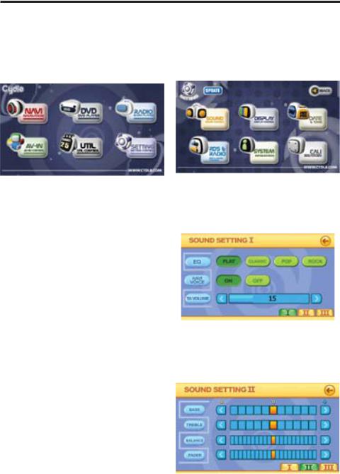
Main Menu
Main Menu Screen |
Settings Menu Screen |
Press the Power button in the upper right hand corner of the Radio screen or press the BAND button on the faceplate or remote control to access the Main Menu.
The Main menu screen is where you access all of the VRVD640G’s features and functions. To access all features and functions by tapping on touch screen buttons.
The NAVI button starts the Navigation software.
The DVD button will access the DVD player, USB port and SD card slot. If there isn’t any media installed a Warning Screen “NO DISC” will be displayed.
The RADIO button will start the radio, or return you to it if it is already on.
The AV-IN button will display the video signal from the AV-IN jack on the rear of the unit.
The UTIL button will access the Calculator and Calendar.
The Settings button will display the settings screen.
The Settings screen allows the user to access Sound, Display, Date & Time, RDS & Radio, System, and Calibration menus.
The Sound Settings I
From this screen the user can select Equalizer Pre-sets for listening to different music
types. You may also adjust System Volume as well as selecting Stereo or mono output.
The Sound Settings II
From this screen the user can adjust the Bass, Treble, Balance, and Fader settings.
16

Menu Screens
The Sound Settings III
The Sound Setting III screen turns the following functions ON & OFF. BEEP, LOUD, and SUB WOOFER.
The Display Settings
DISPLAY I Screen
The Display I screen allows you to adjust the brightness of the screen backlight.
DISPLAY II Screen
The Display II screen allows you to adjust the settings for the use of a 2nd monitor with the VRVD640G.
Date & Time Settings
The Date & Time Settings screen allows you to set the date & time for the unit.
RDS & Radio Settings
The RDS & Radio screens allow you to customize the Radio’s RDS funcionality.
17

Menu Screens
System Information
The system information screen displays the hardware and software information of the VRVD640G.
Calibration Screen
The calibration screen is used by the system to ensure the accuracy of the user’s touch when using the touch screen.
Follow the on-screen instructions when using this screen.
UTIL Utility Control Screen
The Utility screen is used to access the Calculator and Calendar.
Calculator
The calculator operates just like most other calculators.
CONTROL |
FUNCTION |
MC |
Memory Clear |
MR |
Memory Restore |
MS |
Save to Memory |
M+ |
Add # in Memory |
<_ |
Backspace |
CE |
Clear Display |
+/= |
Plus and Minus Alternate |
. |
Dot Display |
sqrt |
extract the square root |
%Percent
1/x |
Fraction |
=Enter
Exit Calculator
C |
Clear |
+,-,*,/ |
The four arithmetic operations |
0-9 |
Numeric Display |
Calendar
Use the button on the Calendar to check dates, Days of the week, and months.
18

Radio Mode
Radio Operations
1. Radio Mode
When you first start the VRVD640G, the radio is the default mode of operation. The Radio interface screen will be displayed on the touch screen. You may also access the radio from the touch screen Main Menu, or the Band button on the faceplate or remote control.
|
Band |
Frequency |
Equalizer Setting |
|
|
|
|
||
|
|
|
|
|
|
|
|
|
Exit Radio |
Access GPS |
|
FM1 |
|
|
FLAT |
|
|
|
|
|
NAVI |
87.50 |
|
|
|
Volume Level |
|||
|
|
MHz |
|
|
|
|
|||
Mute & Un-Mute |
|
|
|
|
|
|
|
|
|
GPS Voice |
NAVI |
|
|
|
|
|
|
|
|
Previous Station |
VOICE |
|
|
|
|
20 |
|
Next Station |
|
|
|
|
|
|
|
|
|
||
|
87.50 |
|
90.00 |
98.00 |
|
|
|
|
|
|
106.00 |
|
108.00 |
87.50 |
|
|
|
|
|
|
|
|
|
|
|
|
|
|
|
Memorized Pre-Set Radio Stations
2. Radio Bands
This unit comes with five bands - three FM (FM1, FM2, and FM3) and two AM Bands. Each of the four bands can store up to six preset stations, for a total of 30 (18-FM & 12-AM) pre-set memory stations. Each time the Band button on the face plate or remote control is pressed, the radio changes bands in the following order:
 FM1----FM2----FM3----AM1----AM2
3. Tuning
There are 3 types of Tuning modes; Pre-set, Scan, and Manual.
a) Pre-set Tuning
To use Pre-set tuning you must first save the radio stations to memory;
1.Press the BAND button to select the desired band, FM1, FM2, FM3, or AM1, AM2
2.Tune to the station you want to save as a Pre-Set.
3.Press and hold the Pre-set button at the bottom of the screen for 2 seconds. You will hear a beep to confirm that the Pre-Set has been stored.
If the Pre-set button has a previously
stored station it will be overwritten. Up to 6 stations can be saved as a Pre-Set.
b) Seek Tuning
Press the << button once to seek a lower frequency or the >> button to seek a higher frequency. When using Seek tuning the radio will seek for and tune to the next strongest radio signal.
c) Manual Tuning
Press and hold the << or >> button until the word manual appears on the LCD. Then press << to tune to a lower frequency or the >> button to tune to a higher frequency. Leave the unit idle for a few seconds and it will return to scan tuning.
Radio Data System (RDS)
On the Main Menu, press the Settings Button, then on the Settings Screen press the RDS & Radio button to access the RDS Settings Screens.
TA (Traffic Announcement) SEEK mode:
The Radio will automatically seek and tune in stations that transmitting Traffic Announcements.
When a tuned station does not transmit any Traffic Program (TP), the radio will re-tune to a new station that is transmitting TP info. You can select re-tune times of 30 seconds (RETUNE SHORT) or 90 seconds (RETUNE LONG) from the RDS Menu 2 above.
TA (Traffic Announcement) ALARM mode:
In TA ALARM, re-tuning does not occur. The current station keeps playing, but you will be alerted to Traffic Announcements either by a beeping sound or muting of the music (determined by the selected PI setting on the RDS Menu 1 above).
PI Mode
The RDS Menu 1 allows for selection of PI (Program ID) Sound or Mute.
When Sound is selected, a beep will be
19

Radio Mode
heard when a PI message is sent by the station.
When Mute is selected, the sound will decrease in volume when a PI message is sent by the station.
Regional Mode
Regional Mode is used in countries where national broadcasters run “Region Specific” programming.
For use in the USA, “REG” in the RDS Menu 1 should be turned OFF.
RETUNE Mode
On the RDS Menu 2, select RETUNE
SHORT or RETUNE LONG.
This selects the initial time of Auto TA or
PI search.
MASK Mode
MASK DPI is the default mode. It will mask only Alternate Frequencies (AF) with different PI.
MASK ALL will mask all AF that do not have enough RDS field strength.
EONTA
DX on pulls in weaker stations, and LOCAL only pulls in strong local stations.
GIVE US A CALL, WE'LL HELP YOU INSTALL.
PLEASE DO NOT RETURN PRODUCT TO STORE.
Visit us on the WEB
www.vr-3.com
For Information and Technical Assistance, Call Toll-Free in U.S.A. and Canada.
1-800-445-1797
20
Multimedia Mode
In DVD mode the VRVD640G plays files saved on disc as well as files saved on USB Memory sticks and SD Cards. The compatible file types MP3, WMA, MPEG, JPEG, VCD & DIVX.
See page 5 for more information about the disc and memory types.
Touch Screen
The functions and display characteristics can be adjsuted with the buttons on the faceplate, the remote control and the touchscreen. Below are two photos of the touch screen buttons and their functions.
GPS Toggle |
|
USB |
DISC SD |
Hide MENU |
|
|
|
|
|
||
|
|
Voice ON/OFF |
Up |
||
|
|
||||
Display Adjustments |
Enter |
||||
|
|||||
|
|
|
Left |
Right |
|
Skip Play/Pause Stop Skip
Down
The buttons on the top left are for the navigation system. NAVI will display the Navigation software, and NAVI VOICE toggles the GPS voice ON & OFF.
Touching the icons for the USB, DISC, and SD will change the playback to to the touched icon.
The arrow buttons are used to navigate the folder list, file list, and file type list. The Enter button confirms your choice.
Use the buttons on the bottom left for playback. They operate the same as corresponding buttons on the faceplate and remote control.
The button on the left side will display the controls for adjusting the display characteristics
File List Screen
The below screen is displayed when a Dics, SD card or USB memory with A/V files
Multimedia Operations
1. Inserting a Disc/SD Card/USB Memory DISC: Press the Eject button on the top left side of the faceplate, the faceplate will automatically drop down to give you access the disc slot. Insert a disc into the disc slot with the label side facing up. The disc will automatically load.
SD CARD: Press the open button on the top right side of the faceplate, then remove the faceplate.
Insert the SD card into the SD card slot until you hear a click. Re-install the face plate. To remove the SD card press the card until you hear a click, then release it and remove.
USB MEMORY: On the bottom right side of the faceplate remove the plug from the USB port, then insert the USB Memory.
To remove a USB memory stick, just pull it out ot the USB port. Replace the USB port’s cover when not in use.
2. Ejecting a Disc
Press the eject button on the top left side of the faceplate and the faceplate will automatically drop down and the disc will eject. Remove the disc. If the disc is not removed within 11 seconds it will automatically reload itself.
21
 Loading...