


ISTRUZIONI I
INSTRUCTIONS GB BEDIENUNGSANLEITUNG D MODE D’EMPLOI F INSTRUCCIONES E INSTRUCTIES NL

I - ITALIANO
INTRODUZIONE |
4 |
MONTAGGIO SENSORE DI CADENZA |
9 |
ISTRUZIONI DEL SOFTWARE |
4 |
Procedura di montaggio sensore di cadenza |
9 |
CARDIOFREQUENZIMETRO |
4 |
Procedura di montaggio magnete |
9 |
PENDENZA |
4 |
CONNESSIONE CAVI |
10 |
COPYRIGHT |
4 |
Connessione PC-Console |
10 |
IMPORTANTE |
5 |
Connessione Console-Unità di Resistenza |
10 |
NOTE |
5 |
Connessione dell’unità |
10 |
Requisiti minimi del sistema |
5 |
UTILIZZO DEL REALAXIOM SENZA COMPUTER |
10 |
NOME E LISTA DEI COMPONENTI |
6 |
UTILIZZO DEL REALAXIOM CON IL COMPUTER |
11 |
ISTRUZIONI DI ASSEMBLAGGIO |
7 |
INSTALLAZIONE DEL PROGRAMMA DEL REALAXIOM |
11 |
SCHEMA GENERALE SEMPLIFICATO |
7 |
INSTALLAZIONE DELLE VIDEOCORSE |
11 |
ASSEMBLAGGIO CAVALLETTO |
7 |
Informazioni sullo smaltimento del prodotto |
11 |
MONTAGGIO UNITÀ |
8 |
1) Nell’Unione Europea |
11 |
MONTAGGIO BICI SUL CAVALLETTO |
8 |
2) In paesi che non fanno parte dell’UE |
11 |
MONTAGGIO CONSOLE SUL MANUBRIO |
9 |
GARANZIA |
52 |
GB - ENGLISH
INTRODUCTION |
12 |
ASSEMBLY OF THE CADENCE SENSOR |
17 |
SOFTWARE INSTRUCTIONS |
12 |
How to fit the cadence sensor |
17 |
HEART RATE MONITOR |
12 |
Procedure for fitting the magnet |
17 |
SLOPE |
12 |
CABLE CONNECTIONS |
18 |
COPYRIGHT |
12 |
Connecting the PC to the console |
18 |
IMPORTANT |
13 |
Connecting the console to the resistance unit |
18 |
IMPORTANT POINTS |
13 |
Connecting the resistance unit |
18 |
Minimum system requirements |
13 |
USING REALAXIOM WITHOUT COMPUTER |
18 |
PARTS LIST |
14 |
USING REALAXIOM WITH COMPUTER |
19 |
ASSEMBLING INSTRUCTIONS |
15 |
INSTALLING THE REALAXIOM PROGRAMME |
19 |
SIMPLIFIED GENERAL DIAGRAM |
15 |
INSTALLING THE REALAXIOM VIDEO COURSE |
19 |
ASSEMBLING THE STAND |
15 |
Information on the disposal of the product |
19 |
ASSEMBLING THE UNIT |
16 |
1) Within the European Union |
19 |
MOUNTING THE BICYCLE ON THE STAND |
16 |
2) In non-EU countries |
19 |
ASSEMBLY OF THE CONSOLE TO THE HANDLEBAR |
17 |
WARRANTY |
52 |
D - DEUTSCH
ALLGEMEINE INFORMATIONEN |
20 |
MONTAGE VOM TRITTFREQUENZSENSOR |
25 |
SOFTWARE-ANLEITUNG |
20 |
Anbringen vom Trittfrequenzsensor |
25 |
HERZFREQUENZMESSER |
20 |
Anbringung vom Magneten |
25 |
GEFÄLLE |
20 |
ANSCHLIESSEN DER KABEL |
26 |
COPYRIGHT |
20 |
Anschluss vom PC an die Konsole |
26 |
WICHTIGER HINWEIS |
21 |
Anschluss der Konsole an die Widerstandseinheit |
26 |
HINWEIS |
21 |
Anschluss der Widerstandseinheit |
26 |
MINDESTAUSSTATTUNG PC |
21 |
GEBRAUCH VOM REALAXIOM OHNE COMPUTER |
26 |
BEZEICHNUNG UND VERZEICHNIS DER KOMPONENTEN 22 |
GEBRAUCH VOM REALAXIOM MIT COMPUTER |
27 |
|
MONTAGEANLEITUNG |
23 |
INSTALLATION DER REALAXIOM-SOFTWARE |
27 |
ALLGEMEINES VEREINFACHTES SCHEMA |
23 |
INSTALLIERUNG DER VIDEO-RENNEN |
27 |
ZUSAMMENBAU VOM STÄNDER |
23 |
Hinweise zur Entsorgung des Produkts |
27 |
MONTAGE DER WIDERSTANDSEINHEIT |
23 |
1) Innerhalb der Europäischen Union |
27 |
MONTAGE VOM FAHRRAD AUF DEM STÄNDER |
24 |
2) In Nicht-EU-Ländern |
27 |
MONTAGE DER KONSOLE AM LENKER |
25 |
GARANTIE |
52 |
|
|
|
|
|
|
|
|

F - FRANÇAIS
INTRODUCTION |
28 |
MONTAGE DU CAPTEUR DE CADENCE |
33 |
MODE D’EMPLOI DU LOGICIEL |
28 |
Procédé pour le montage du capteur de cadence |
33 |
CARDIO-FREQUENCEMETRE |
28 |
Procédé pour le montage de l’aimant |
33 |
PENTE |
28 |
BRANCHEMENT DES FILS |
34 |
COPYRIGHT |
28 |
Connexion PC-Console |
34 |
IMPORTANT |
29 |
Connexion Console-Unité de Résistance |
34 |
REMARQUES |
29 |
Connexion de l’unité |
34 |
CONDITIONS MINIMUMS REQUISES DU SYSTEME |
29 |
UTILISATION DE REALAXIOM SANS ORDINATEUR |
34 |
NOM ET LISTE DES PIECES |
30 |
UTILISATION DE REALAXIOM AVEC ORDINATEUR |
35 |
INSTRUCTIONS POUR L’ASSEMBLAGE |
31 |
INSTALLATION DU LOGICIEL DE REALAXIOM |
35 |
SCHEMA GENERAL SIMPLIFIE |
31 |
INSTALLATION DES VIDEO COURSES |
35 |
ASSEMBLAGE DU SUPPORT |
31 |
Informations sur l’élimination du produit |
35 |
MONTAGE DE L’UNITÉ |
32 |
1) En Union Européenne |
35 |
MONTAGE DU VELO SUR LE SUPPORT |
32 |
2) Danslespaysquinefontpaspartiedel’UnionEuropéenne 35 |
|
MONTAGE DE LA CONSOLE SUR LE GUIDON |
33 |
GARANTIE |
52 |
E - ESPAÑOL
INTRODUCCIÓN |
36 |
MONTAJE DETECTOR DE CADENCIA |
41 |
INSTRUCCIONES DEL SOFTWARE |
36 |
Procedimiento de montaje detector de cadencia |
41 |
FRECUENCIA CARDIACA |
37 |
Procedimiento de montaje magneto |
41 |
PENDIENTE |
37 |
CONEXIÓN CABLES |
42 |
COPYRIGHT |
37 |
Conexión PC-Consola |
42 |
IMPORTANTE |
36 |
Conexión Consola-Unidad de Resistencia |
42 |
NOTAS |
37 |
Conexión de la unidad |
42 |
Requisitos mínimos del sistema |
37 |
USO DEL REALAXIOM SIN ORDENADOR |
42 |
NOMBRE Y RELACIÓN DE LOS COMPONENTES |
38 |
USO DEL REALAXIOM CON EL ORDENADOR |
43 |
INSTRUCCIONES DE ENSAMBLAJE |
39 |
INSTALACIÓN DEL PROGRAMA DEL REALAXIOM |
43 |
ESQUEMA GENERAL SIMPLIFICADO |
39 |
INSTALACIÓN DE LOS VIDEO-CARRERAS |
43 |
ENSAMBLAJE CABALLETE |
39 |
Informaciones acerca de la eliminación del producto |
43 |
MONTAJE UNIDAD |
40 |
1) En la Unión Europea |
43 |
MONTAJE BICI SOBRE EL CABALLETE |
40 |
2) En países que no son parte de la Unión Europea |
43 |
MONTAJE CONSOLA EN EL MANILLAR |
41 |
GARANTIA |
52 |
NL - DUTCH
INLEIDING |
44 |
DE KADANSSENSOR MONTEREN |
49 |
AANWIJZINGEN M.B.T. DE SOFTWARE |
44 |
Hoe de kadanssensor plaatsen |
49 |
HARTSLAGMETER |
44 |
Werkwijze om de magneet te monteren |
49 |
HELLING |
44 |
KABELVERBINDINGEN |
50 |
AUTEURSRECHT |
44 |
De PC met de console verbinden |
50 |
BELANGRIJK |
45 |
De weerstandsunit met de console verbinden |
50 |
AANDACHTSPUNTEN |
45 |
De weerstandsunit aansluiten |
50 |
Minimum systeemvereisten |
45 |
DE REALAXIOM GEBRUIKEN ZONDER COMPUTER |
50 |
ONDERDELENLIJST |
46 |
DE REALAXIOM GEBRUIKEN MET COMPUTER |
51 |
MONTAGEVOORSCHRIFTEN |
47 |
HET REALAXIOM PROGRAMMA INSTALLEREN |
51 |
VEREENVOUDIGD ALGEMEEN DIAGRAM |
47 |
DE REALAXIOM VIDEORIT INSTALLEREN |
51 |
HET FRAME ASSEMBLEREN |
47 |
Informatie over de vernietiging van het product |
51 |
DE UNIT ASSEMBLEREN |
48 |
1) Binnen de Europese Unie |
51 |
DE FIETS IN HET FRAME PLAATSEN |
48 |
2) In niet-EU landen |
51 |
DE CONSOLE OP HET STUUR PLAATSEN |
49 |
GARANTIE |
52 |
|
|
|
|
|
|
|
|

I
INTRODUZIONE
Molte grazie per aver acquistato il ciclosimulatore Elite RealAxiom.
Elite RealAxiom è un dispositivo elettronico per effettuare allenamenti e test ciclistici indoor, da interfacciare con un personal computer (Windows) per mezzo di una console applicata al manubrio della bicicletta.
Il programma del RealAxiom permette di allenarsi visualizzando un vero percorso che scorre con la stessa velocità del ciclista regalando una simulazione della strada molto più realistica. Con Elite RealAxiom è inoltre possibile programmare qualsiasi percorso.
Il software provvederà a regolare automaticamente la resistenza in funzione della pendenza, velocità e peso del ciclista, rilevando frequenza cardiaca, potenza, velocità, elevazione, cadenza, distanza, tempo e altre informazioni.
Elite RealAxiom permette inoltre di salvare tutti i dati e richiamarli per analisi e comparazioni, con la possibilità di stampare i relativi report.
È necessario leggere questo manuale per arrivare ad una profonda conoscenza del prodotto e del suo funzionamento.
ISTRUZIONI DEL SOFTWARE
Nel presente manuale non c’è alcuna indicazione sull’uso del programma. Una completa guida dell’uso del programma si trova sull’Help del programma stesso.
Per accedere a tale Help, è necessario installare il programma. Le istruzioni per installare il programma sono descritte al paragrafo “Utilizzo del RealAxiom con il computer – Installazione del programma”.
Una volta installato il programma,
si può accedere all’Help in 2 diversi modi:
•premere il tasto F1 della tastiera;
•sul menù del programma, scegliere “Help – Contenuto Help”.
CARDIOFREQUENZIMETRO
Il RealAxiom ha al suo interno un ricevitore per cardiofrequenzimetri a fascia toracica. Ciò gli permette di rilevare il valore della frequenza cardiacadelciclistaedivisualizzarlosulloschermo durante la corsa. Tale cardiofrequenzimetro non è fornito con il prodotto.
Il ricevitore del cardiofrequenzimetro del RealAxiom è compatibile con tutti i trasmettitori di tipo“standard”,cioèconfrequenzeditrasmissione di 5 KHz.
Alcuni trasmettitori codificati (ad es. Polar) potrebbero non essere compatibili con il nostro ricevitore.
ATTENZIONE: sistemi integrati wireless che rilevanooltrealbattitocardiacoanchelacadenza di pedalata e la velocità, possono interferire col la lettura del battito cardiaco del RealAxiom. In questo caso allontanare il sensore della cadenza dalla pedivella.
PENDENZA
Anche la massima pendenza simulabile varia in funzione della velocità e del peso. Infatti, la potenza necessaria per affrontare una salita varia in funzione della velocità con cui la si affronta (più veloce, più potenza) e del peso (per “sollevare” più peso ci vuole più potenza). Quando la situazione richiede una potenza maggiore di quella massima, allora RealAxiom continua a fornire la potenza massima e di conseguenza non si sentirà aumentare ulteriormente la resistenza.
Ad esempio, per un ciclista di 60Kg alla velocità di 24km/h la pendenza massima simulabile è circa 10%.
COPYRIGHT
Nessuna della parti di questo manuale può essere riprodotta o trasmessa senza l’autorizzazione scritta di ELITE S.r.l.
Il software di Elite RealAxiom e il relativo codice sono di proprietà di ELITE S.r.l.
Il software è coperto dalle leggi internazionali sul copyright.
Il software di Elite RealAxiom deve essere trattato come ogni altro materiale coperto da copyright, come i libri.
Usando il software si accetta di non modificare o adattare il programma. Si accetta anche di non decompilare, disassemblare o tentare in qualsiasi maniera di scoprire il codice nativo del software.
4
I
IMPORTANTE
•Non frenare mai durante l’utilizzo del ciclosimulatore, ciò danneggia irreparabilmente il rullino e pneumatico.
•Per l’allenamento con il RealAxiom utilizzare pneumatici slick a carcassa rigida da 23 mm o più larghi.
•La pressione deve essere di 7-8 atm (4 atm per ruote MTB). Un pneumatico troppo stretto e una pressione insufficiente causano un’usura irreparabile del rullino elastogel e del pneumatico.
•Utilizzare pneumatici slick anche su MTB (si migliora l’aderenza, si riduce il rumore e il consumo).
•Attenzione alla pressione tra pneumatico e rullino: compiere 3 giri completi della vite di regolazione della piastra da quando il rullino toccailpneumatico.Seilpneumaticocontinua a slittare sul rullino compiere un altro giro della vite e rendere più progressivo lo sforzo
sul pedale. L’allenamento con il pneumatico che slitta danneggia irreparabilmente il rullino elastogel e il pneumatico.
•Durante l’uso del RealAxiom con rullino Elastogel, una leggera usura del rullino rientranellanormalità.ItesteseguitiinElite hanno dimostrato che dopo un uso continuo per 15000 Km, il consumo del rullino si aggira sui 0.1 mm. Essendo lo spessore totale 15 mm, un consumo ben superiore non impedisce un corretto funzionamento del ciclosimulatore. Contestazioni dovute ad utilizzo improprio o negligente, non verranno riconosciute.
•La console che va sul manubrio non è impermeabile.Attenzioneanonsudaresopra la console, perché si potrebbe danneggiare il circuito elettronico.
•Non conservate il RealAxiom in luoghi bagnati o umidi. Questo potrebbe danneggiare i componenti elettronici.
NOTE
Posti vicino a TV, radio e motori generano forti onde e interferenze elettromagnetiche, che possono causare misurazioni non corrette.
Evitate di usare il dispositivo e la console entro un raggio di circa un metro e mezzo da altri trasmettitori.
Non usate altri apparecchi wireless simultaneamente. Ci potrebbero essere delle misurazioni sbagliate.
Evitare di esporre l’unità e la console alla luce diretta del sole per periodi prolungati quando non sono utilizzate.
Periodicamente controllare la posizione e le condizioni di montaggio del sensore di cadenza e del magnete.
Non applicare mai detergenti chimici (benzine o diluenti) su nessuna parte dell’Elite RealAxiom.
Requisiti minimi del sistema:
Processore: |
Pentium 3 |
Sistema operativo: |
Windows 2000 / XP / Vista |
Hard disk: |
10Gb 7200 giri/minuto |
Ram: |
256 Mb |
Monitor: |
800x600 |
Drive: |
DVD-ROM |
Porte: |
I/O USB |
5
I
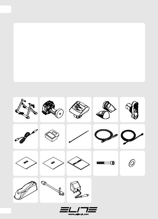
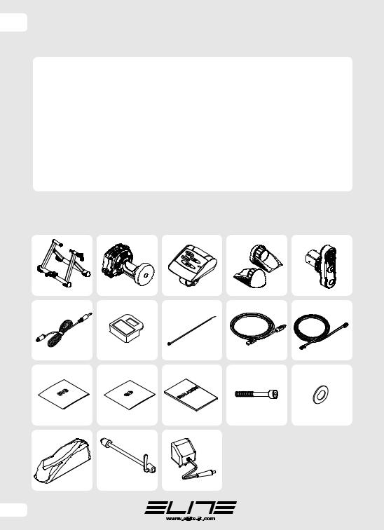
NOME E LISTA DEI COMPONENTI
Il tuo RealAxiom dovrebbe includere i seguenti componenti:
|
QUANTITÀ |
NUMERO |
|
QUANTITÀ |
NUMERO |
CAVALLETTO DELL’UNITÀ REALAXIOM |
1 |
1 |
CAVO CONSOLE-UNITÀ DI |
|
|
UNITÀ DI RESISTENZA ELETTRONICA |
1 |
2 |
RESISTENZA (8 POLI) |
1 |
J |
CONSOLE PER IL MANUBRIO |
1 |
3 |
DVD - ROM |
2 |
K |
PIEDINI |
2 |
4 |
CD - ROM |
1 |
L |
MANOVELLA |
1 |
5 |
MANUALE ISTRUZIONI |
1 |
M |
SENSORE DI CADENZA |
1 |
6 |
VITE M6 X 16 |
3 |
N |
MAGNETE |
1 |
7 |
RONDELLE M6 |
2 |
O |
FASCETTE DI FISSAGGIO PICCOLE |
10 |
8 |
TRAVEL BLOCK |
1 |
P |
CAVO USB PC-CONSOLE |
1 |
9 |
QUICK RELEASE |
1 |
Q |
|
|
|
ALIMENTATORE |
1 |
R |
ATTENZIONE: nel manuale, per agevolare l’identificazione dei vari pezzi, vicino al nome è riportato tra parentesi il numero d’identificazione. Questo numero è riferito alla seconda colonna della tabella soprastante e alle figure di pag 6.
1 |
B |
C |
D |
E |
F G H I J
K L M N O
P Q R
6
I
ISTRUZIONI DI ASSEMBLAGGIO
NOTA: NON CONNETTERE IL CAVO USB AL COMPUTER PRIMA DI AVER INSTALLATO
IL PROGRAMMA REALAXIOM
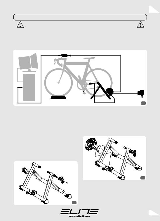
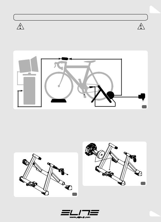
SCHEMA GENERALE SEMPLIFICATO
Nella figura 1 è rappresentato lo schema dei collegamenti del RealAxiom. In questa figura in nero sono rappresentate le parti che sono
contenute nella scatola del RealAxiom, mentre in grigio ci sono le parti che devono essere in possesso dell’utilizzatore.
|
console |
|
|
monitor |
|
|
|
|
|
sensore di |
|
|
|
cadenza |
unità di |
computer |
|
|
|
|
|
resistenza |
|
|
|
magnete |
|
|
Travel Block |
|
1 |
|
|
|
ASSEMBLAGGIO CAVALLETTO |
MONTAGGIO UNITÀ |
Nella figura 2 è mostrato come devono essere montati i piedini 4 sul cavalletto 1. In caso fosse difficile inserirli aiutarsi con un martello di gomma. Fare attenzione che le basi dei piedini siano parallele al suolo e che il cavalletto sia aperto nella sua massima estensione.
Nella stessa figura è mostrato anche come applicare la manovella 5. Quando s’inserisce la manovella sul perno a vite si deve prestare attenzione affinché la superficie piana presente sul perno vada a combaciare con quella presente all’interno della manovella. Utilizzare la vite M6X16 per fissare la manovella.
2
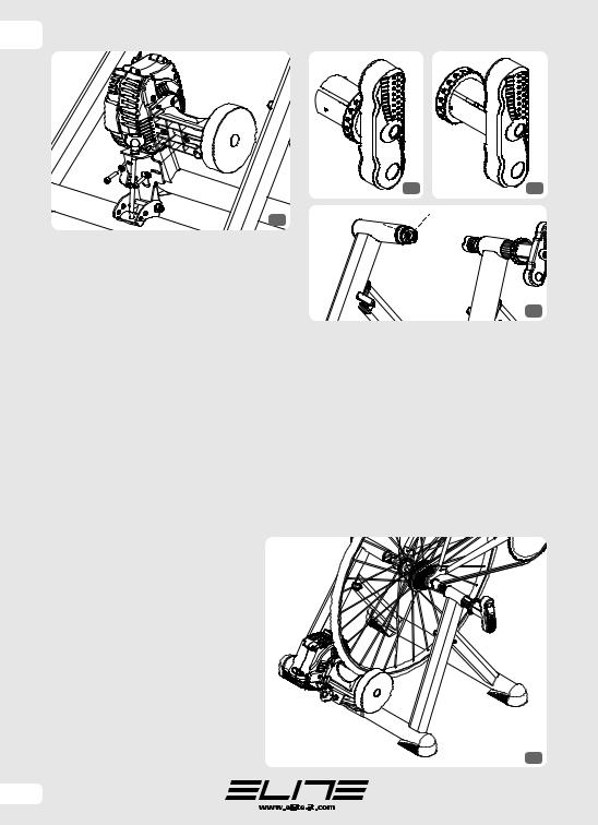
In figura 3 è mostrato come deve essere montata l’unità 2 sul cavalletto 1.
ATTENZIONE IL VOLANO DELL’UNITÀ È MOLTO PESANTE. ANCHE PICCOLI URTI POTREBBERO PIEGARE L’ALBERINO E RENDERE INUTILIZZABILE TUTTO IL SISTEMA.
3
Per il fissaggio dell’unità di resistenza sulla piastra, utilizzare le viti M6 N e le rondelle Ø6xØ14 O come mostrato in figura 4. Sulla piastra i fori sono fatti in modo da poter regolare la posizione dell’unità in base alla posizione della ruota rispetto al rullino.
7
I
4
Prima di montare l’unità, assicurarsi che il cavalletto sia perfettamente posizionato sul pavimento, al massimo della sua estensione e che la piastra di supporto sia in posizione orizzontale.
FARE ATTENZIONE PERCHÉ L’UNITÀ È MOLTO PESANTE E POTREBBE CAUSARE LA CHIUSURA DEL CAVALLETTO.
MONTAGGIO BICI SUL CAVALLETTO
Innanzi tutto, abbassare completamente l’unità 2, svitando la vite di regolazione della piastra. Se la manovella 5 è bloccata, spostare l’anello di bloccaggio verso la manovella, come mostrato in figura 5. Regolare l’apertura delle boccole supporto, ruotando in senso antiorario la manovella, fino a fine corsa.
Assicurarsi che il bloccaggio rapido della ruota posteriore della bicicletta sia ben stretto. Per un bloccaggio sicuro della bicicletta sul cavalletto, assicurarsi che la boccola sinistra (dove viene bloccata la leva del bloccaggio rapido) abbia lo scarico rivolto verso l’alto (vedi fig. 7).
Mettere in posizione la bicicletta inserendo l’estremità sinistra del bloccaggio rapido posteriore nella boccola di sinistra del cavalletto 1. Ruotando l’apposita manovella, serrare il supporto destro sede mozzo fino a quando la boccola destra non entra in contatto con l’estremità destra del bloccaggio rapido. A contatto avvenuto,
ruotare per circa 1/2 giro la manovella per bloccare la bici al cavalletto.
Bloccare la manovella utilizzando l’anello di bloccaggio, spostandolo verso il cavalletto (fig. 6). Quando l’anello si trova
in quest’ultima posizione, la manovella non può più ruotare.
Verificare la stabilità della bicicletta tirando e spingendo il tubo orizzontale del telaio ed agendo sulla sella.
5 |
6 |
7
Qualora la bicicletta non risultasse stabile, assicurarsi che il bloccaggio rapido e la sua levetta siano correttamente posizionati e che il perno di bloccaggio sia ben serrato. Se il bloccaggio rapido della ruota non è compatibile con le boccole del cavalletto bisogna sostituire il bloccaggio rapido con uno compatibile.
Avvitare la vite di regolazione dell’unità fino a mettere il rullino a contatto con la ruota.
Da questa posizione, ruotare per tre giri la vite di regolazione per ottenere la giusta pressione del rullino sulla ruota. Qualora pedalando si sentisse la ruota slittare, far compiere un altro giro alla vite di regolazione.
La figura 8 mostra come deve risultare la bici una volta montata sul cavalletto.
8
8
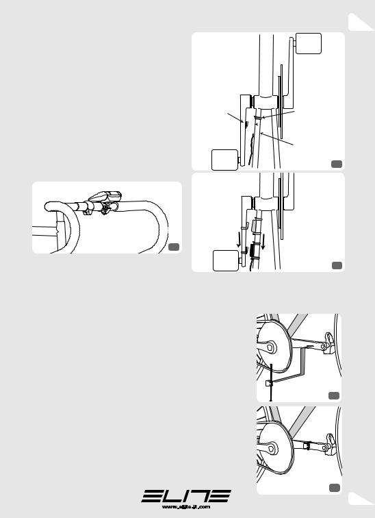
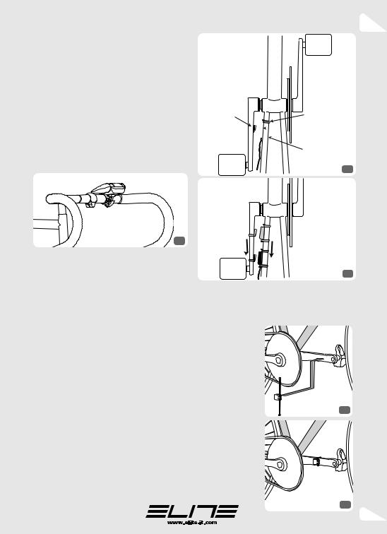
MONTAGGIO CONSOLE SUL MANUBRIO
Attaccare il morsetto al manubrio. Per chiudere il morsetto, agganciare la testa della leva sulla apposita sede (come mostrato in fig. 9). Qualora il diametro del manubrio fosse troppo piccolo o grande, è possibile avvitare/svitare la vite di bloccaggio del supporto della quantità necessaria. Se la regolazione della vite non fosse sufficiente, è possibile rimuovere uno o entrambi i gommini presenti sul morsetto.
Una volta posizionato il morsetto sul manubrio, chiuderlo e girare la vite per fissarlo. La figura 9 mostra come deve essere la console una volta montata sul manubrio.
Prima di continuare, assicurarsi che la console sia ben bloccata al manubrio in posizione leggermente inclinata.
9
MONTAGGIO SENSORE DI CADENZA
Il sensore di cadenza 6 serve per rilevare il numero di pedalate durante la corsa. Va montato sul telaio della bicicletta, mentre il magnete 7 va fissato sulla pedivella. Insieme al sensore e al magnete sono fornite alcune fascette di plastica 8 per fissare il sensore, il magnete e il filo alla bicicletta.
Procedura di montaggio sensore di cadenza
Applicare il sensore di cadenza 6 al telaio, sul tubo orizzontale che dal movimento centrale va all’asse della ruota posteriore (lato sinistro).
Utilizzare 2 fascette come mostrato in figura 10. Prima di stringere saldamente le fascette, completare il montaggio del magnete e verificare il corretto funzionamento durante una corsa di prova. Se il sensore non funziona correttamente è possibile che il magnete passi troppo distante dal sensore. Per risolvere il problema, avvicinare il sensore al magnete facendo scorrere magnete e sensore verso l’asse posteriore della bici (fig. 11).
I
MAGNETE |
FASCETTA |
FASCETTA


 SENSORE
FASCETTA
10
11
Procedura di montaggio magnete
Inserire una fascetta 8 nel magnete 7. Dopodi-
chè appoggiare il magnete con la fascetta sulla |
|||||
pedivella e stringere la fascetta (figure 12 e 13). |
|||||
Utilizzare |
le |
altre |
|||
fascette |
presenti |
||||
nella |
confezione |
||||
per |
fissare |
il |
filo |
||
del |
|
sensore |
al |
||
telaio della bici, in |
|||||
modo da prevenire |
|||||
il |
contatto |
dello |
|||
stesso con |
i raggi |
||||
della ruota o con la |
|||||
pedivella. |
|
|
12 |
||
A |
corredo |
|
con il |
||
RealAxiom ci sono |
|||||
numerose |
fascette |
||||
e non devono esse- |
|||||
re necessariamen- |
|||||
te utilizzate tutte. |
|||||
|
|
|
|
|
13 |
9

I
CONNESSIONE CAVI
NOTA: NON CONNETTERE IL CAVO USB AL COMPUTER PRIMA DI AVER INSTALLATO IL PROGRAMMA REALAXIOM
Connessione dell’unità
Collegare la spina del sensore di cadenza 6 con l’unità di resistenza. La presa per tale spina è sul guscio dell’unità di resistenza rivolta verso il basso.
Inserire il trasformatore in una presa elettrica e collegare la spina jack del trasformatore R al connettore presente nell’unità di resistenza.
Verificare che l’alimentazione funzioni correttamente controllando che il led verde sulla console sia acceso. Il led verde dovrebbe lampeggiare o essere acceso. Se il led è spento allora la connes-
14sione console - unità e/o unità - rete elettrica, non è stata eseguita correttamente.
Connessione PC-console
Per connettere la console del RealAxiom al PC, utilizzare il cavo USB 9. La spina più larga e piatta va inserita in una delle prese USB del computer, mentre l’altra va sulla console (vedi figura 14).
ATTENZIONE: NON CONNETTERE IL CAVO USB AL COMPUTER PRIMA DI AVER INSTALLATO IL PROGRAMMA REALAXIOM.
La diversità dei connettori, non permette di sbagliare.
Connessione Console-unità di resistenza
Per la connessione tra console e unità di resistenza, utilizzare il cavo piatto J. Una delle due estremità va inserita nel connettore libero della console (vedi figura 14), mentre l’altro va inserito nell’apposito connettore presente sull’unità di resistenza. La diversità dei connettori, non permette di sbagliare.
Fissare i 3 cavi all’unità utilizzando i fermacavo presenti, al fine prevenire incidentali rotture dei connettori della scheda elettronica (vedi figura 15).


 15
15
UTILIZZO DEL REALAXIOM SENZA COMPUTER
Èpossibile utilizzare il RealAxiom anche senza l’uso del computer. Se la console non è in comunicazione con il programma, allora si mette in modalità autonoma. In modalità autonoma il led verde presente sulla console lampeggia.
Ogni volta che il RealAxiom entra in modalità autonoma, esso imposta la resistenza al minimo.
Èpossibile variare la resistenza premendo i tasti “+” e “-” della console. Premendo il tasto “+” si aumenta la resistenza e premendo il tasto “-” si diminuisce. La resistenza del RealAxiom, in modalità autonoma, è stata suddivisa in 8 livelli.
Dopo 20 secondi di inutilizzo, la resistenza del RealAxiom torna a zero indipendentemente dal livello di resistenza impostato.
10
I
UTILIZZO DEL REALAXIOM CON IL COMPUTER
INSTALLAZIONEDELPROGRAMMADELREALAXIOM
Inserire il CD nel lettore CD-rom e seguire le istruzioni del software d’installazione.
Per accettare le impostazioni di default (scelta consigliata) è sufficiente premere il tasto “Invio” in tutte le schermate del programma d’installazione.
Le schermate del programma d’installazione sono le seguenti.
Schermata |
Schermata di selezione |
Schermata di selezione |
di introduzione |
della cartella programmi |
della cartella di installazione |
Schermata per la creazione |
Schermata di riassunto |
Schermata |
delle icone del programma |
dei dati immessi |
di installazione avvenuta |
Alla fine della procedura di installazione, sul desktop di Windows è presente l’icona del programma RealAxiom. Fare doppio click con il mouse sull’icona per avviare il programma.
ORA È POSSIBILE CONNETTERE IL CAVO USB AL COMPUTER.
INSTALLAZIONEDELLEVIDEOCORSE
Inserire il DVD della Corsa Video. L’installazione della Corsa Video dovrebbe partire automaticamente.
ATTENZIONE: L’INSTALLAZIONE DELLA CORSA VIDEO POTREBBE RICHIEDERE PARECCHI MINUTI.
INFORMAZIONI SULLO SMALTIMENTO DEL PRODOTTO
1) NELL’UNIONE EUROPEA
Attenzione:Persmaltireilpresentedispositivononutilizzareilnormalebidonedellaspazzatura!
Le apparecchiature elettriche ed elettroniche usate devono essere gestite a parte ed in conformità alla legislazione che richiede il trattamento, il recupero e il riciclaggio adeguato dei suddetti
prodotti. In seguito alle disposizioni attuate dagli Stati membri, i privati residenti nella UE possono conferire le apparecchiature elettriche ed elettroniche usate a centri di raccolta designati*.
*Per maggiori informazioni si prega di contattare l’autorità locale competente.
Lo smaltimento corretto del presente prodotto contribuirà a garantire che i rifiuti siano sottoposti al trattamento, al recupero e al riciclaggio necessari prevenendone il potenziale impatto negativo sull’ambiente e sulla salute umana, che potrebbe derivare da un’inadeguata gestione dei rifiuti.
2) IN PAESI CHE NON FANNO PARTE DELL’UNIONE EUROPEA
Se si desidera eliminare il presente prodotto, contattare le autorità locali e informarsi sul metodo di smaltimento.
11

GB
INTRODUCTION
Congratulations on your purchase of the Elite RealAxiom cycling simulator.
Elite RealAxiom is an electronic device for indoor training and tests; it interfaces with a PC (Windows) by means of a console fitted to the handlebar of your bike.
Elite RealAxiom allows you to view real-life courses while training which will run at the same speed you are running on your trainer offering a highly realistic on-road simulation. Elite RealAxiom allows you to programme any kind of route. The software automatically adjusts resistance depending on gradient, speed and weight and indicates heart rate, power, speed, height, pedalling frequency, distance, time and other important information.
Elite RealAxiom allows you to save all racing and test results for future analysis and print the relative reports.
Please read this manual with care in order to become perfectly familiar with the product and how it works.
SOFTWARE INSTRUCTIONS
This manual does not give any instructions regarding use of the programme. A complete guide to using the programme is given in the programme Help.
To access the Help guide it is necessary to install the programme. The instructions for installing the programme are given in the section “Use of RealAxiom with the computer – Programme installation”.
After installing the programme, the Help guide can be accessed in two different ways:
•press button F1 on the keyboard;
•select “Help – Help Contents” from the programme menu.
HEART RATE MONITOR
Elite RealAxiom incorporates a receiver for chest-band heart rate monitors. This allows it to measure your heart rate while training and
visualise it on the monitor. The heart rate monitor is not supplied with the product.
Elite RealAxiom’s heart rate monitor receiver is compatible with all “standard” transmitters, i.e., those featuring 5 KHz transmission frequencies. Some coded transmitters (i.e. Polar) may not be compatible with our receiver.
WARNING: integrated wireless systems that measure cadence and speed, in addition to heart rate, may interfere with the heart rate readings of RealAxiom. In order to avoid this, remove the sensor form the crank.
SLOPE
The maximum simulatable slope on the RealAxiom is a function of speed and the weight of the individual rider. In fact, the power required to pedal up a slope is function of the speed (faster = more power) and of the weight (the heavier the rider, the more power is required to climb any given slope). Each rider has a maximum slope given his weight [i.e., for a 60kg (130lbs) cyclist at 24Km/h (15mph) the maximum simulatable slope is about 10%.]
So, if the rider is already riding at his maximum power, and the slope increases, the actual the resistance won’t increase, even though the steeper slope is indicated on the screen.
COPYRIGHT
No part of this manual may be reproduced or transmitted without the written authorization of Elite S.r.l.
The Elite RealAxiom software and relative code are property of Elite S.r.l.
International copyright law protects the software. The Elite RealAxiom software must be treated like any other copyrighted material, such as books.
Users undertake not to modify or adapt the programme. Users also undertake not to decompile, disassemble or attempt in any way to discover the native software code.
12

GB
IMPORTANT
•Never brake when using the RealAxiom trainer, as this could permanently damage the Elastogel roller and the tyre.
•For training with the RealAxiom use slick tyres with rigid carcass of 23 mm or wider. The pressure must be 7-8 atm / 100-120 psi for racing wheels (4 atm for MTB wheels). A tyre that is too narrow and insufficient pressure will cause increased wear of the Elastogel roller and the tyre.
•Use slick tyres also on MTBs (this will improve grip, reduce noise and wear).
•Pay attention to the pressure between tyre and roller: tighten the plate adjustment screw three complete turns from when the roller touches the tyre. If the tyre still slips on the roller, tighten the screw another turn and make the pressure on the pedal more progressive. Training with the tyre slipping will permanently damage the Elastogel roller and the tyre.
•During use of the RealAxiom with Elastogel roller, slight wear of the roller is to be considered normal. Tests carried out at Elite have shown that after continuous use for 20000 Km, the wear on the roller is about 0.1 mm. As the total thickness is 15 mm, even far higher wear does not prevent correct operation of the cycle-simulator. Warranty claims resulting from improper or negligent use will not be acknowledged.
•The console that is fitted on the handlebar is not waterproof. Take care not to sweat over the console, as the sweat could damage the electronic circuit.
•Do not keep the RealAxiom in wet or damp places. This could damage the electronic components.
IMPORTANT POINTS
If placed near TV’s, radios and motors, the equipment generates strong magnetic waves and interference that may give rise to incorrect readings.
Do not use the device and the console within a distance of about one and a half metres from other transmitters.
Do not use other wireless equipment at the same time. This may give rise to incorrect measurements.
Do not expose the unit and the console to direct sunlight for long periods when they are not in use.
Check the position and assembly conditions of the frequency sensor and magnet at regular intervals.
Never use chemical detergents (benzene or thinners) on any part of the Elite RealAxiom.
Minimum System Requirements:
Processor: |
Pentium 3 |
Operative System: |
Windows 2000 / XP / Vista |
Hard disk: |
10 GB7200 rpm |
Ram: |
256 Mb |
Monitor: |
800x600 |
Drive: |
DVD-ROM |
Ports: |
I/O USB |
13
GB
PARTS LIST
Your RealAxiom electronic trainer is made of the following components:
|
QUANTITY |
NUMBER |
|
QUANTITY |
NUMBER |
REALAXIOM UNIT STAND |
1 |
1 |
CONSOLE-RESISTANCE |
|
|
ELECTRONIC RESISTANCE UNIT |
1 |
2 |
UNIT CABLE (8 POLES) |
1 |
J |
HANDLEBAR CONSOLE |
1 |
3 |
DVD CONTAINING REAL-LIVE VIDEOS |
2 |
K |
FEET |
2 |
4 |
CD CONTAINING REALAXIOM SOFTWARE |
1 |
L |
HANDLE |
1 |
5 |
INSTRUCTIONS MANUAL |
1 |
M |
CADENCE SENSOR |
1 |
6 |
M6 X 16 SCREW |
3 |
N |
MAGNET |
1 |
7 |
M6 WASHER |
2 |
O |
CLAMPS |
10 8 |
TRAVEL BLOCK |
1 |
P |
|
PC-CONSOLE CABLE WITH USB SOCKET |
1 |
9 |
QUICK RELEASE |
1 |
Q |
|
|
|
POWER SUPPLY |
1 |
R |
ATTENTION: in order to make it easier to identify the various pieces in the manual, the ID number is shown in brackets next to the name. This number is shown in the second column in the above table and in the illustration on page 14 of this manual.
1 |
B |
C |
D |
E |
F G H I J
K L M N O
P Q R
14
GB
ASSEMBLING INSTRUCTIONS
WARNING. NOTE. DO NOT CONNECT THE USB CABLE TO THE COMPUTER
BEFORE INSTALLING THE REALAXIOM SOFTWARE.
SEMPLIFIED GENERAL DIAGRAM
Illustration 1 shows the diagram of the RealAxiom. The parts in black are supplied in the RealAxiom box, while the user must provide the parts in grey.
|
handlebar console |
|
monitor |
|
|
|
cadence |
|
|
sensor |
resistance |
PC |
|
|
|
unit |
|
|
|
|
|
magnet |
|
|
Travel Block |
1 |
|
|
ASSEMBLING THE STAND |
ASSEMBLING THE UNIT |
Illustration 2 shows how to fit the feet 4 to the stand 1. Use a rubber mallet if necessary. Make sure that the bottoms of the feet are parallel with the floor and that the stand is completely open.
The illustration also shows how to fit the handle 5. When fitting the handle to the screw pin, make sure the flat surface of the pin matches the flat inside of the handle.
Use the M6x16 screw to fix the handle 5.
2
Illustration 4 shows how to fit the unit 2 to the stand 1.
CAUTION: THE FLYWHEEL OF THE UNIT IS VERY HEAVY. EVEN MINOR IMPACTS COULD BEND THE SHAFT AND MAKE THE ENTIRE SYSTEM UNUSABLE.
3
Use M6 bolts N and Ø6xØ14 washers O to fix the unit as shown in illustration 4. The pair of holes on the resistance unit plate allows lateral adjustment of the resistance unit.
15

GB
5 |
6 |
4
Before fitting the unit make sure that the stand is perfectly positioned on the floor, completely opened, and that the support plate is horizontal.
TAKE CARE, AS THE UNIT IS VERY HEAVY AND
COULD CAUSE THE STAND TO CLOSE.
7
MOUNTING THE BIKE ON THE STAND
First of all, completely lower the unit 2, by loosening the stand adjustment screw. If the handle 5 is locked, move the lock ring toward the handle as shown in illustration 5.
Adjust the space between the bushings by turning the handle, anti-clockwise as far as it will go. Make sure that the rear wheel QR skewer is well tightened. To have a safe locking of the bicycle on the stand, make sure that the left support cup (where the quick release lever is blocked) is positioned with the undercutting facing upwards (see ill. 7)
Place the bike on the stand by fitting the left-hand side of the rear QR skewer into the left-hand side bushing of the stand 1. Turn the handle 5, to tighten the righthand support of the hub housing until the right-hand bushing touches the right-hand end of the QR skewer. Then rotate the handle 5 by about half a turn in order to
lock the bike to the stand.
Lock the handle by moving the lock ring towards the stand (illustration 6). When the ring is in this position, the handle can no longer turn.
Check the stability of the bike by pulling and pushing the top tube of the frame and the saddle.
If the bike is unstable, make sure that the
QR skewer and its lever are correctly positioned and that the lock pin is well tightened. If the quick-release device is not compatible with the bushings, it needs to be substituted with one that is compatible.
Tighten the adjustment screw on the support plate until the roller touches the wheel.
Then rotate the adjustment screw by three turns in order to obtain the correct pressure of the roller on the wheel. If the wheel slips while you are pedalling, rotate the adjustment screw by another complete turn.
Illustration 8 shows the correct position of the bike mounted to the stand.
8
16
ASSEMBLY OF THE CONSOLE
TO THE HANDLEBAR
Attach the bracket to the handlebar, preferably close to the stem. To block the bracket, position the bolt lever as shown in illustration 8. The bolt regulation of the bracket can be adjusted for a secure fix to the handlebar. It may be necessary to remove one or both the rubber shims from the bracket in order to fit larger diameter handlebars.
Illustration 9 shows the correct position of the console mounted to the handlebar.
Check the console is securely fixed to the handlebar and slightly inclined before starting.
9
GB
MAGNET |
CLAMP |
CLAMP 


 SENSOR
CLAMP
10
ASSEMBLY OF THE CADENCE SENSOR
The cadence sensor 6 counts the number of pedal strokes per minute made during the course. It is fitted to the frame of the bike while the magnet 7 is fitted to the pedal crank.
Some plastic clamps 8 are supplied for fixing the sensor, the magnet and the cable to the bike.
How to fit the cadence sensor
Fix the sensor 6 to the horizontal tube connecting the central mechanism to the axis of the rear wheel (left-hand side). Use 2 clamps 8 as shown in illustration 10.
Before tightening the clamps complete the assembly of the magnet and verify the correct functioning during a trial course. If the sensor doesn’t function correctly it could be possible that the magnet is positioned too far from the sensor. In this case push the sensor closer to the magnet by sliding the magnet and the sensor towards the axis of the rear wheel (illustration 11).
11
Procedure for fitting the magnet
Fit a tight clamp 8 into the magnet 7.
Then place the magnet and clamp on the crank |
|||||
and tighten the clamp (illustration 12 and 13). |
|
||||
Use |
the |
other |
|
||
clamps in the pack |
|
||||
to fix |
the |
sensor |
|
||
cable to the frame |
|
||||
of the bike in order |
|
||||
to prevent |
it |
from |
|
||
touching the |
spo- |
|
|||
kes of the wheel or |
|
||||
the pedal crank. |
12 |
||||
Several clamps are |
|||||
|
|||||
supplied with |
the |
|
|||
RealAxiom and not |
|
||||
all of them need to |
|
||||
be used. |
|
|
|
||
13
17
 Loading...