


Project A3
Copyright © 2011 by ELENCO®, All rights reserved. No part of this book shall be reproduced by |
753154 |
any means; electronic, photocopying, or otherwise without written permission from the publisher. |
Patent #‘s: 7,144,255, 7,273,377, & other patents pending |

Table of Contents
Basic Troubleshooting |
1 |
Project Listings |
|
9 |
||
Parts List |
2 |
How to Use Snap Circuits® |
|
10 |
||
About Your Snap Circuits® Parts |
3 - 5 |
Part A – Introductory Projects (A1-A30) |
11 - 27 |
|||
Introduction to Electricity |
6 |
Part B – Microcontroller Projects (B1-B27) |
28 - 58 |
|||
DO’s and DON’Ts of Building Circuits |
7 |
Part C – To Go Further |
|
59 |
||
Advanced Troubleshooting |
8 |
Other Snap Circuits® Products |
|
62 |
||
! |
WARNING TO ALL PROJECTS WITH A ! SYMBOL - Moving parts. Do not touch the motor or fan during operation. Do not |
! |
||||
lean over the motor. Do not launch the fan at people, animals, or objects. Eye protection is recommended. |
|
|||||
|
|
|
|
|
|
|
WARNING: SHOCK HAZARD - Never connect Snap Circuits® |
! |
WARNING: CHOKING HAZARD - Small |
to the electrical outlets in your home in any way! |
parts. Not for children under 3 years. |
Conforms to ASTM F963-96A
Requirements for your computer: Windows® XP (or later) or Mac OS X 10.2 (or later) or Linux, 512MB RAM, 500MB of hard-disk space, USB port, and CD-ROM drive.
Basic Troubleshooting
1.Most circuit problems are due to incorrect assembly, always double-check that your circuit exactly matches the drawing for it.
2.Be sure that parts with positive/negative markings are positioned as per the drawing.
3.Be sure that all connections are securely snapped.
4.Try replacing the batteries.
5.If the motor spins but does not balance the fan, check the black plastic piece with three prongs on the motor shaft.
ELENCO® is not responsible for parts damaged due to incorrect wiring.
Note: If you suspect you have damaged parts, you can follow the Advanced Troubleshooting procedure on page 8 to determine which ones need replacing.
WARNING: Always check your wiring before turning on a circuit. Never leave a circuit unattended while the batteries are installed. Never connect additional batteries or any other power sources to your circuits. Discard any cracked or broken parts.
!Batteries:
•Use only 1.5V AA type, alkaline batteries (not incl.).
•Insert batteries with correct polarity.
•Non-rechargeable batteries should not be recharged. Rechargeable batteries should only be charged under adult supervision, and should not be recharged while in the product.
•Do not mix alkaline, standard (carbon-zinc), or rechargeable (nickel-cadmium) batteries.
•Do not mix old and new batteries.
•Remove batteries when they are used up.
•Do not short circuit the battery terminals.
•Never throw batteries in a fire or attempt to open its outer casing.
•Batteries are harmful if swallowed, so keep away from small children.
-1-

Parts List (Colors and styles may vary) Symbols and Numbers
Important: If any parts are missing or damaged, DO NOT RETURN TO RETAILER. Call toll-free (800) 533-2441 or e-mail us at: help@elenco.com. Customer Service • 150 Carpenter Ave. • Wheeling, IL 60090 U.S.A.
Qty. |
|
ID |
Name |
Symbol |
Part # |
|
Qty. |
|
ID |
Name |
Symbol |
Part # |
|||
|
|
|
|
|
|
|
|
|
|
|
|
|
|
|
|
r 1 |
|
|
|
Base Grid |
|
6SCBG |
|
r 1 |
|
|
|
Fan Blade |
|
6SCM1F |
|
|
|
|
(11.0” x 7.7”) |
|
|
|
|
|
|
||||||
|
|
|
|
|
|
|
|
|
|
|
|
|
|
|
|
|
|
|
|
|
|
|
|
|
|
|
|
|
|
|
|
|
|
|
|
1-Snap Wire |
|
6SC01 |
|
|
|
|
|
NPN Transistor |
|
6SCQ2 |
|
r 6 |
|
1 |
|
|
|
r 2 |
|
Q2 |
|
|
|||||
|
|
|
|
|
|
|
|
|
|
|
|
|
|
|
|
|
|
|
|
|
|
|
|
|
|
|
|
|
|
|
|
|
|
|
|
|
|
|
|
|
|
|
|
100Ω Resistor |
|
|
|
r 9 |
|
2 |
|
2-Snap Wire |
|
6SC02 |
|
r 1 |
|
R1 |
|
|
6SCR1 |
||
|
|
|
|
|
|
|
|
|
|
|
|
|
|
|
|
|
|
|
|
|
|
|
|
|
|
|
|
|
|
|
|
|
|
|
|
|
|
|
|
|
|
|
|
1kΩ Resistor |
|
|
|
r 4 |
|
3 |
|
3-Snap Wire |
|
6SC03 |
|
r 2 |
|
R2 |
|
|
6SCR2 |
||
|
|
|
|
|
|
|
|
|
|
|
|
|
|
|
|
|
|
|
|
|
|
|
|
|
|
|
|
|
|
|
|
|
|
|
|
4-Snap Wire |
|
6SC04 |
|
|
|
|
|
10kΩ Resistor |
|
6SCR4 |
|
r 3 |
|
4 |
|
|
|
r 2 |
|
R4 |
|
|
|||||
|
|
|
|
|
|
|
|
|
|
|
|
|
|
|
|
|
|
|
|
|
|
|
|
|
|
|
|
|
|
|
|
|
|
|
|
5-Snap Wire |
|
6SC05 |
|
|
|
|
|
100kΩ Resistor |
|
6SCR5 |
|
r 1 |
|
5 |
|
|
|
r 1 |
|
R5 |
|
|
|||||
|
|
|
|
|
|
|
|
|
|
|
|
|
|
|
|
|
|
|
|
|
|
|
|
|
|
|
|
|
|
|
|
|
|
|
|
6-Snap Wire |
|
6SC06 |
|
|
|
|
|
Photoresistor |
|
6SCRP |
|
r 1 |
|
6 |
|
|
|
r 1 |
|
RP |
|
|
|||||
|
|
|
|
|
|
|
|
|
|
|
|
|
|
|
|
|
|
|
|
|
|
|
|
|
|
|
|
|
|
|
|
|
|
|
|
|
|
|
|
|
|
|
|
|
|
||
r 1 |
|
7 |
|
7-Snap Wire |
|
6SC07 |
|
r 1 |
|
RV |
|
Adjustable Resistor |
|
6SCRV |
|
|
|
|
|
|
|
|
|
|
|
|
|
|
|
|
|
|
|
|
|
|
|
|
|
|
|
|
|
|
|
|
|
|
|
|
|
Battery Holder - uses |
|
|
|
|
|
|
|
|
|
|
|
r 1 |
|
B3 |
|
|
6SCB3 |
|
r 1 |
|
S1 |
|
Slide Switch |
|
6SCS1 |
||
|
|
3 1.5V type AA (not Included) |
|
|
|
|
|
||||||||
|
|
|
|
|
|
|
|
|
|
|
|
|
|
|
|
|
|
|
|
|
|
|
|
|
|
|
|
|
|
|
|
|
|
|
|
470μF Capacitor |
|
|
|
|
|
|
|
|
|
|
|
r 1 |
|
C5 |
|
|
6SCC5 |
|
r 1 |
|
S2 |
|
Press Switch |
|
6SCS2 |
||
|
|
|
|
|
|
|
|
|
|
|
|
|
|
|
|
|
|
|
|
|
|
|
|
|
|
|
|
|
|
|
|
r 1 |
|
|
|
Red Light Emitting |
|
6SCD1 |
|
r 1 |
|
|
|
8 Ohm Speaker |
|
6SCSP |
|
|
D1 |
|
|
|
|
SP |
|
|
|||||||
|
|
Diode (LED) |
|
|
|
|
|
||||||||
|
|
|
|
|
|
|
|
|
|
|
|
|
|
|
|
|
|
|
|
|
|
|
|
|
|
|
|
|
|
|
|
r 1 |
|
|
|
Green Light Emitting |
|
6SCD2 |
|
r 1 |
|
|
|
Microcontroller IC |
|
6SCU21 |
|
|
D2 |
|
|
|
|
U21 |
|
|
|||||||
|
|
Diode (LED) |
|
|
|
|
|
||||||||
|
|
|
|
|
|
|
|
|
|
|
|
|
|
|
|
|
|
|
|
|
|
|
|
|
|
|
|
|
|
|
|
r 1 |
|
|
|
Jumper Wire (Black) |
|
6SCJ1 |
|
r 1 |
|
|
|
Microphone |
|
6SCX1 |
|
|
|
|
|
|
|
X1 |
|
|
|||||||
|
|
|
|
|
|
|
|
|
|
|
|
|
|
|
|
|
|
|
|
|
|
|
|
|
|
|
|
|
|
|
|
r 1 |
|
|
|
Jumper Wire (Red) |
|
6SCJ2 |
|
r 1 |
|
|
|
CD with Software |
|
9CDXP50 |
|
|
|
|
|
|
|
|
|
|
|
|
|
|
|
|
|
r 1 |
|
|
DC Motor |
|
6SCM1 |
|
r 1 |
|
|
|
Programming Cable |
|
9TLSCXP |
||
|
M1 |
|
|
|
|
|
|
|
|||||||
|
|
|
|
|
|
|
|
|
|
|
|
|
|
|
|
|
|
|
|
|
|
|
|
|
|
|
|
|
|
|
|
You may order additional / replacement parts at our website: www.snapcircuits.net |
|
|
|
||||||||||||
|
|
|
|
|
|
|
|
|
|
|
|
|
|
|
|
-2-

About Your Snap Circuits® XP Parts
(Part designs are subject to change without notice).
BASE GRID
The base grid is a platform for parts and wires.
It functions like the printed circuit boards used in most electronic products, or like how walls are used for mounting the electrical
wiring in your home.
BATTERY HOLDER
The batteries (B3) produce an electrical voltage using a chemical reaction. This “voltage” can be thought of as electrical pressure, pushing electricity through a circuit just like a pump pushes water through pipes. This voltage is much lower and much safer than that used in your house wiring. Using more batteries increases the “pressure”, therefore, more electricity flows.
SNAP WIRES & JUMPER WIRES
The blue snap wires are wires used to connect components. They are used to electricity and do circuit performance. in different lengths to
arrangement of connections
on the base grid.
Battery Holder (B3)
The red and black jumper wires make flexible connections for times when using the
would be difficult. They also are
used to make connections off the base grid.
Wires transport electricity just like pipes are used to transport water. The colorful plastic coating protects them and prevents electricity from getting in or out.
The motor (M1) converts electricity into mechanical motion. An electric current in the motor will turn the shaft and the motor blades, and the fan
the motor.
Fan
How does electricity turn the shaft in the motor? The answer is magnetism. Electricity is closely related to magnetism, and an electric current flowing in a wire has a magnetic field similar to that of a very, very tiny magnet. Inside the motor is a coil of wire with many loops wrapped around metal plates. This is called an electromagnet. If a large electric current flows through the loops, it will turn ordinary metal into a magnet. The motor shell also has a magnet on it. When electricity flows through the electromagnet, it repels from the magnet on the motor shell and the shaft spins. If the fan is on the motor shaft, then its blades will create airflow.
Power Contacts
Magnet
Shell
Shaft
Electromagnet
-3-

About Your Snap Circuits® XP Parts
RESISTORS |
|
SLIDE & PRESS SWITCHES |
|
RED & GREEN LEDs |
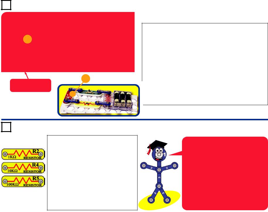
Resistors “resist” the flow of electricity and are used to control or limit the current in a circuit. Snap Circuits® XP includes 100Ω (R1), 1kΩ (R2), 10kΩ (R4), and 100kΩ (R5) resistors (“K” symbolizes 1,000, so R4 is really 10,000Ω). Materials like metal have very low resistance (<1Ω), while materials like paper, plastic, and air have near-infinite resistance. Increasing circuit resistance reduces the flow of electricity.
The slide & press switches (S1 & S2) connect (pressed or “ON”) or disconnect (not pressed or “OFF”) the wires in a circuit. When ON they have no effect on circuit performance. Switches turn on electricity just like a faucet turns on water from a pipe.
Slide & Press Switches (S1 & S2)
SPEAKER
The red & green LED’s (D1 & D2) are light emitting diodes, and may be thought of as a special one-way light bulb. In the “forward” direction, (indicated by the “arrow” in the symbol) electricity flows if the voltage exceeds a turn-on threshold (about 1.5V for red and a little higher for green); brightness then increases. A high current will burn out the LED, so the current must be limited by other components in the circuit. LED’s block electricity in the “reverse” direction.
Resistors (R1, R2, R4, & R5)
The adjustable resistor (RV) is a 50kΩ resistor but with a center tap that can be adjusted between 200Ω and 50kΩ.
The speaker (SP) converts electricity into sound by making mechanical
vibrations. These vibrations create variations in air pressure, which travel across the room. You “hear” sound when your ears feel these air pressure variations.
Speaker (SP)
Adjustable Resistor (RV)
The photoresistor (RP) is a light-sensitive resistor, its value changes from nearly infinite in total darkness to about 1000Ω when a bright light shines on it.
MICROPHONE
The microphone (X1) is actually a resistor that changes in value when changes in air pressure (sounds) apply pressure to its surface. Its resistance typically varies from around 1kΩ in silence to around 10kΩ when you blow on it
LED’s (D1 & D2)
CAPACITOR
The 470μF capacitor (C5) can store electrical pressure (voltage) for periods of time. This storage ability allows it to block stable voltage signals and pass changing ones. Capacitors are used for filtering and delay circuits.
Photoresistor (RP) |
Microphone (X1) |
Capacitor (C5) |
-4-

About Your Snap Circuits® XPTM Parts
TRANSISTORS
The NPN (Q2) transistors are components that use a small electric current to control a large current, and are used in switching, amplifier, and buffering applications. They are easy to miniaturize, and are the main
building blocks of integrated circuits including the microprocessor and memory circuits in computers.
NPN Transistor (Q2)
MICROCONTROLLER
The microcontroller IC (U21) includes the PICAXE® 08M integrated circuit. This is a mini computer which can be programmed to perform different tasks, including monitoring things and making things happen. The PICAXE® 08M has a special programming interface that makes it very easy to use.
CABLES
The programming cable is used to program and communicate with the U21 microcontroller.
Programming Cable
Microcontroller IC (U21)
Microcontroller outputs cannot control the motor or speaker directly, an interface transistor must be used. Microcontroller outputs can control Snap Circuits® LEDs directly.
Note: There is additional information for the PICAXE® 08M integrated circuit at www.picaxe.co.uk.
U21 Microcontroller IC:
(+) - power from batteries (GND) - power return to batteries S-In - Programming input snap S-Out /Snap 0 - Serial Output 0 Snap 1 - IN1/OUT1/ADC1
Snap 2 - IN2/OUT2/ADC2 Snap 3 - IN3
Snap 4 -IN4/OUT4/ADC4
Notes for using the PICAXE®-08M in other applications:
Power source:
This should be 4.5V or 5V. Higher voltages may damage the part.
S-In connection:
The U21 platform has an internal 10KΩ resistor between the S-In and GND snaps, and a 22KΩ resistor between the S-In snap and the microcontroller. These facilitate use of the programing cable.
Several snaps can be used as either inputs, outputs, or analog to digital converters:
as Outputs: Each output can supply or receive up to 20 mA. This is enough to light an LED, but an interface transistor must be used when controlling a motor or speaker.
as Inputs: An input should be above 80% of the power source voltage to be high, or below 20% of the power source voltage to be low.
as Analog to Digital Converters (ADC): The ADC range is the power source voltage range. Circuit resistance should be less than 20KΩ, or false readings may occur.
-5-

Introduction to Electricity
What is electricity? Nobody really knows. We only know how to produce it, understand its properties, and how to control it. Electricity is the movement of sub-atomic charged particles (called electrons) through a material due to electrical pressure across the material, such as from a battery.
Power sources, such as batteries, push electricity through a circuit, like a pump pushes water through pipes. Wires carry electricity, like pipes carry water. Devices like LEDs, motors, and speakers use the energy in electricity to do things. Switches and transistors control the flow of electricity like valves and faucets control water. Resistors limit the flow of electricity.
The electrical pressure exerted by a battery or other power source is called voltage and is measured in volts (V). Notice the “+” and “–” signs on the battery; these indicate which direction the battery will “pump” the electricity.
The electric current is a measure of how fast electricity is flowing in a wire, just as the water current describes how fast water is flowing in a pipe. It is expressed in amperes (A) or milliamps (mA, 1/1000 of an ampere).
The “power” of electricity is a measure of how fast energy is moving through a wire. It is a combination of the voltage and current (Power = Voltage x Current). It is expressed in watts (W).
The resistance of a component or circuit represents how much it resists the electrical pressure (voltage) and limits the flow of electric current. The relationship is Voltage = Current x Resistance. When the resistance increases, less current flows. Resistance is measured in ohms (Ω), or kilo ohms (kΩ, 1000 ohms).
Nearly all of the electricity used in our world is produced at enormous generators driven by steam or water pressure. Wires are used to efficiently transport this energy to homes and businesses where it is used. Motors convert the electricity back into mechanical form to drive machinery and appliances. The most important aspect of electricity in our society is that it allows energy to be easily transported over distances.
Note that “distances” includes not just large distances but also tiny distances. Try to imagine a plumbing structure of the same complexity as the circuitry inside a portable radio - it would have to be large because we can’t make water pipes so small. Electricity allows complex designs to be made very small.
There are two ways of arranging parts in a circuit, in series or in parallel. Here are examples:
Series Circuit
Parallel Circuit
Placing components in series increases the resistance; highest value dominates. Placing components in parallel decreases the resistance; lower value dominates.
The parts within these series and parallel sub-circuits may be arranged in different ways without changing what the circuit does. Large circuits are made of combinations of smaller series and parallel circuits.
-6-

DO’s and DON’Ts of Building Circuits
After building the circuits given in this booklet, you may wish to experiment on your own. Use the projects in this booklet as a guide, as many important design concepts are introduced throughout them. Every circuit will include a power source (the batteries), a resistance (which might be a resistor, capacitor, motor, integrated circuit, etc.), and wiring paths between them and back. You must be careful not to create “short circuits” (very lowresistance paths across the batteries, see examples at right) as this will damage components and/or quickly drain your batteries. Only connect the U21 microcontroller IC (the PICAXE 08M) using configurations given in the projects, incorrectly doing so may damage it. ELENCO® is not responsible for parts damaged due to incorrect wiring.
Here are some important guidelines:
ALWAYS USE EYE PROTECTION WHEN EXPERIMENTING ON YOUR OWN.
ALWAYS include at least one component that will limit the current through a circuit, such as the speaker, capacitors, ICs (which must be connected properly), motor, microphone, photoresistor, or resistors.
ALWAYS use LEDs, transistors, and switches in conjunction with other components that will limit the current through them. Failure to do so will create a short circuit and/or damage those parts.
ALWAYS connect capacitors so that the “+” side gets the higher voltage.
ALWAYS disconnect your batteries immediately and check your wiring if something appears to be getting hot.
ALWAYS check your wiring before turning on a circuit.
ALWAYS connect U21 microcontroller IC using configurations given in the projects or as per the connection description on page 5.
NEVER connect to an electrical outlet in your home in any way.
NEVER touch the motor when it is spinning at high speed.
Warning to Snap Circuits® owners: Do not use
`parts from other Snap Circuits® sets with this kit. Other sets use higher voltage which could damage the microcontroller and other parts.
You are encouraged to tell us about new programs and circuits you create. If they are unique, we will post them with your name and state on our website at www.snapcircuits.net/kidkreations.htm. Send your suggestions to ELENCO®: elenco@elenco.com.
ELENCO® provides a circuit designer so that you can make your own Snap Circuits® drawings. This Microsoft® Word document can be downloaded from www.snapcircuits.net/SnapDesigner.doc or through the www.snapcircuits.net website.
Examples of SHORT CIRCUITS - NEVER DO THESE!!!
Placing a 3-snap wire directly across the batteries is a SHORT CIRCUIT.
`
NEVER
DO!
`
NEVER
DO!
is also a CIRCUIT.
When the slide switch (S1) is turned on, this large circuit has a SHORT CIRCUIT path (as shown by the arrows). The short circuit prevents any other portions of the circuit from ever working.
` |
|
|
|
|
|
|
||
|
|
|
|
|
|
` |
||
|
||||||||
NEVER |
|
|
|
|
|
|
|
NEVER |
DO! |
|
|
|
|
|
|
|
|
|
|
|
|
|
|
|
DO! |
|
|
|
|
|
|
|
|
|
|
|
|
|
|
|
|
|
|
|
|
|
|
|
|
|
|
|
|
WARNING: SHOCK HAZARD - Never connect Snap Circuits® _to the electrical outlets in your home in any way!
-7-

Advanced Troubleshooting (Adult supervision recommended)
ELENCO® is not responsible for parts damaged due to incorrect wiring.
If you suspect you have damaged parts, you can follow this procedure to systematically determine which ones need replacing:
(Note: Some of these tests connect an LED directly across the batteries without another component to limit the current. Normally this might damage the LED, however Snap Circuits® LEDs have internal resistors added to protect them incorrect wiring, and will not be damaged.)
1.LEDs (D1 & D2), motor (M1), speaker (SP), and battery holder (B3): Place batteries in holder. Place one of the LEDs directly across the battery holder (LED + to battery +), it should light. Do the same for the motor, it should spin. “Tap” the speaker across the battery holder contacts, you should hear static as it touches. If none work, then replace your batteries and repeat. If still bad, then the battery holder is damaged.
2.Jumper wires:
Use this minicircuit to test each jumper wire, the LED should light.
3.Snap wires: Use this mini-circuit to test each of the snap wires, one at a time. The LED should light.
4.Slide switch (S1) and Press switch (S2):
Use this mini-circuit; if the LED doesn’t light then the slide
switch is bad. Replace the slide switch with the press switch to test it.
5.100Ω (R1), 1kΩ (R2), and 10kΩ (R4)
resistors: Use the mini-circuit from test 4 but replace the switch with the 100Ω resistor
(R1); the LED will be bright if the resistor is good. Next use the 1kΩ and 10kΩ resistors in place of the 100Ω resistor; the LED should be dimmer but still light.
6.Microphone (X1) and Photoresistor (RP):
Use the mini-circuit from test 4 but replace the switch with the microphone (X1, + on right); if blowing into the microphone does not change the LED brightness then the microphone is bad. Replace the microphone with the photoresistor. Waving your hand over the photoresistor (changing the light that shines on it) should change the brightness of the LED or the photoresistor is bad.
7.Adjustable resistor (RV): Build Project #A16, the resistor control lever should turn the LED (D1) on and off; otherwise it is bad.
8.NPN transistor (Q2): Build the mini-circuit shown here. The LED (D2) should only be on if the press switch (S2) is pressed. If otherwise, then the NPN is damaged.
9.470μF capacitor (C5) and 100kΩ resistor (R5): Build the mini-circuit shown here. When you press the switch, the LED should be bright but then slowly get dim, otherwise the
capacitor is bad. Replace the 1kΩ
resistor (R2) with the 100kΩ resistor (R5); the LED should stay on much longer or R5 is bad.
10.Programming cable: Connect the cable to the red LED (D1), orange and yellow wires to (+) and black wire to the other side. Run the AXEpad for Snap Circuits® XP software. Open a terminal (press F8). Type something into the output buffer and press Send. The red LED should flash and what you typed should appear in the input buffer.
11.Microcontroller (U21): Use project B27 (Test the Microcontroller).
ELENCO®
150 Carpenter Avenue Wheeling, IL 60090 U.S.A. Phone: (847) 541-3800 Fax: (847) 520-0085 e-mail: help@elenco.com Website: www.elenco.com
You may order additional / replacement parts at: www.snapcircuits.net
-8-

Project Listings
Part A - Introductory Projects: These projects introduce you to the Snap Circuits® method of building circuits and show how electronic components work. No computer is needed for these projects (some projects use the U21 microcontroller, but with a factory-loaded program).
Part B - Microcontroller Projects: These projects are an introduction to microprocessors, and the flexibility they give by being
Project # |
Title |
Page # |
|
A1 |
Electric Light |
|
11 |
A2 |
Controlling Electricity |
|
11 |
A3 |
Dancing Motor |
|
12 |
A4 |
Electronic Counter |
|
13 |
A5 |
Adding Sound to the Counter |
|
14 |
A6 |
Daylight Alarm Clock |
|
14 |
A7 |
Intruder Alarm |
|
15 |
A8 |
Jukebox |
|
16 |
A9 |
Counting to the Stars |
|
17 |
A10 |
Angles and Distance |
|
18 |
A11 |
Flip-Flop |
|
19 |
A12 |
Adjustable Light Timer |
|
19 |
A13 |
Light Sensitive Timer |
|
20 |
A14 |
Shot in the Dark |
|
20 |
A15 |
Microphone Control |
|
21 |
A16 |
Adjustable Brightness |
|
21 |
A17 |
Conduction Detector |
|
21 |
A18 |
Slider |
|
22 |
A19 |
Parallel Resistors |
|
22 |
A20 |
Series Resistors |
|
22 |
A21 |
Flying Saucer |
|
23 |
A22 |
Transistor |
|
23 |
A23 |
Capacitor Battery |
|
24 |
A24 |
Blow Off Sound |
|
24 |
A25 |
Capacitor Photo Control |
|
25 |
A26 |
Capacitor Photo Control with Slow Shut-off |
25 |
|
A27 |
Photo Switcher |
|
26 |
A28 |
Blow On Sound |
|
26 |
A29 |
Scratchy Amplifier |
|
27 |
programmable. A computer is needed to load programs into the microcontroller, but no other programming knowledge is needed. The microcontroller re-programming procedure is explained in project B1.
Part C - To Go Further: This section is intended for users who would like to develop their own programs for the microcontroller. It also has bonus circuits for owners of other Snap Circuits® models.
Project # |
Title |
Page # |
A30 |
One Shot |
27 |
B1 |
Blinker (Programming the Microcontroller) |
29 |
B2 |
Blinkers |
33 |
B3 |
Four Outputs |
34 |
B4 |
Play a Tune |
35 |
B5 |
Computer Music Box |
36 |
B6 |
Random Sounds |
38 |
B7 |
Sloppy Switches |
39 |
B8 |
Bounceless Switches |
40 |
B9 |
Jukebox with Terminal |
41 |
B10 |
Launch Pad |
42 |
B11 |
Adjustable Blinker |
43 |
B12 |
Basic Light Meter |
44 |
B13 |
Capacitor Discharge |
45 |
B14 |
Sunrise Alarm |
46 |
B15 |
Photon Counter |
47 |
B16 |
Photon Kazoo |
47 |
B17 |
Click Counter |
48 |
B18 |
Super Click Counter |
49 |
B19 |
Data Logger |
50 |
B20 |
Data Logger with Cost |
51 |
B21 |
24 Hour Data Logger |
52 |
B22 |
Digital Voltmeter |
53 |
B23 |
Battery Tester (4V or less) |
54 |
B24 |
Battery Tester (20V or less) |
55 |
B25 |
Clap Light |
56 |
B26 |
Clap Music |
57 |
B27 |
Test the Microcontroller |
58 |
-9-
PART A - Introductory Projects
How to Use Snap Circuits®
Snap Circuits® uses building blocks with snaps to build the different electrical and electronic circuits in the projects. Each block has a function: there are switch blocks, light blocks, battery blocks, different length wire blocks, etc. These blocks are different colors and have numbers on them so that you can easily identify them. The blocks you will be using are shown as color symbols with level numbers next to them, allowing you to easily snap them together to form a circuit.
For Example:
This is the switch block which is green and has the marking S2 on it. The part symbols in this booklet may not exactly match the appearance of the actual parts, but will clearly identify them.
This is a wire block which is blue and comes in different wire lengths.
This one has the number 2 , 3 , 4 , 5 , 6 or 7 on it depending on the length of the wire connection required.
There is also a 1-snap wire that is used as a spacer or for interconnection between different layers.
You need a power source to build each circuit. This is labeled B3 and requires three (3) “AA” batteries (not included).
A large clear plastic base grid is included with this kit to help keep the circuit blocks properly spaced. You will see evenly spaced posts that the different blocks snap into. The base has rows labeled A-G and columns labeled 1-10.
Next to each part in every circuit drawing is a small number in black. This tells you which
level the component is placed at. Place all parts on level 1 first, then all of the parts on level 2, then all of the parts on level 3, etc. Some circuits use the jumper wires to make unusual connections. Just clip them to the metal snaps or as indicated.
Usually when the motor M1 is used, the fan will be placed on it.
No computer is needed for introductory projects (some projects use the U21 microcontroller, but with a factory-loaded program).
Occasionally you may feel static electricity if you touch a circuit when the programming cable is connected, usually when humidity is very low. Don’t worry; this is harmless. It occurs because the cable makes an easy electrical path between your body and the ground, allowing static that has built up on you to dissipate. Sometimes this static electricity may reset the microcontroller (U21), causing it to re-start its program.
Note: While building the projects, be careful not to accidentally make a direct connection across the battery holder (a “short circuit”), as this may damage and/or quickly drain the batteries.
-10-
Project A1
 +
+
 +
+
Placement Level
Numbers
Project A2
Electric Light
Snap Circuits® uses electronic blocks that snap onto a clear plastic grid to build different circuits. These blocks have different colors and numbers on them so that you can easily identify them.
Build the circuit shown on the left by placing all the parts with a black 1 next to them on the board first. Then, assemble parts marked with a 2. Install three (3) “AA” batteries (not included) into the battery holder (B3) if you have not done so already.
When you turn on the slide switch (S1), current flows from the batteries through the switch, red LED (D1), and 100Ω resistor (R1), and back to the batteries. Turning on the switch completes the circuit. When the switch is off, the current can no longer flow back to the battery, so the red LED goes out.
The red LED is just like the ones used in electronic products throughout your home.
Controlling Electricity
Use the circuit built in project A1, but replace the 100Ω resistor (R1) with the 1kΩ resistor (R2). The circuit works the same, but the red LED (D1) will not be as bright.
Now replace the 1kΩ resistor with the 10kΩ resistor (R4). The LED will be dim now.
Now replace the 10kΩ resistor (R4) with the 100kΩ resistor (R5). The 100kΩ has very high resistance, so you may not see any light from the LED.
Take the circuit into a really dark room or curl your fingers around the LED to block the surrounding light. Now you see that the LED is on, though very dim.
Snappy says resistors are used to control or limit the flow of electricity in a circuit. Higher resistor values reduce the flow of electricity in a circuit.
In this circuit, the resistors are used to adjust the LED brightness, to limit the current so the batteries last longer, and to protect the LED from being damaged by the batteries.
What is Resistance? Take your hands and rub them together very fast. Your hands should feel warm. The friction between your hands converts your effort into heat. Resistance is the electrical friction between an electric current and the material it is flowing through.
-11-
|
|
|
Project |
A3 |
|
||||||
+ |
|
|
|
+ |
|
|
|||||
|
|
|
|
|
|
|
|
|
|
|
|
|
|
|
|
|
|
|
|
|
|
|
|
|
|
|
|
|
|
|
|
|
|
|
|
|
|
|
|
|
|
|
|
|
|
|
|
|
|
|
|
|
|
|
|
|
|
|
|
|
|
|
|
|
|
|
|
|
|
|
|
|
|
|
|
|
|
|
|
|
|
|
|
|
|
|
|
|
|
|
|
|
|
|
|
|
|
|
|
|
|
|
|
|
|
|
|
|
|
|
|
|
|
|
|
|
|
|
|
|
|
|
|
|
|
|
|
|
|
|
|
+
Placement Level
|
WARNING: Moving parts. |
Numbers |
! |
Do not touch the fan or |
|
motor during operation. Do |
|
not lean over the motor.
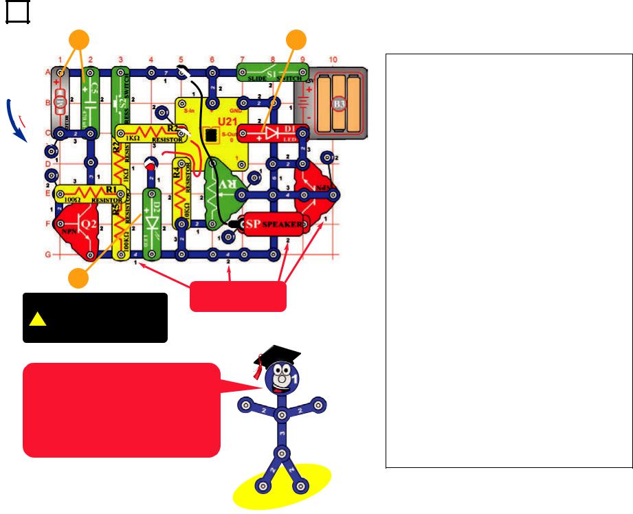
This complex circuit is pictured on the front cover, use that as a guide to help build it.
The program in the microcontroller IC (U21) controls power to the motor (M1), flashes the LED (D2), and sends music to the speaker (SP). The microcontroller is like an electronic brain running the circuit.
Dancing Motor
Note: This circuit requires program Electronic Brain to be in microcontroller U21’s memory. This is loaded into U21 at the Snap Circuits® factory and should still be there, unless you already reprogrammed it. If it has been reprogrammed, you must use project B1 (on page 29) to load program Electronic Brain back into U21 before building this circuit.
Snap Circuits® uses electronic blocks that snap onto a clear plastic grid to build different circuits. These blocks have different colors and numbers on them so that you can easily identify them.
Build the circuit shown above by placing all the parts with a black 1 next to them on the board first. Then, assemble parts marked with a 2. Then, assemble parts marked with a 3. Install three (3) “AA” batteries (not included) into the battery holder (B3) if you have not done so already.
Turn on slide switch (S1) and wait for the red LED (D1) to come on. Push the press switch (S2) and hold it down until music starts. Set the lever on the adjustable resistor (RV) for best sound. The motor (M1) will spin while you push S2, and then will follow the music as it plays. The red & green LEDs (D1 & D2) will blink in time with the music. The fan blade is not necessary and may be removed.
To change the song, push and release S2, then push it again but hold it down until music starts. For more songs, turn S1 off and on, slowly push and release S2 four times, then push and hold down S2 until music starts.
If you flip the motor around then the fan will rise into the air like a flying saucer.
-12-

Project A4 |
Electronic Counter |
We measure many things in quarters. This picture shows only a few of them. How many more can you think of that uses a system like this?
|
|
|
|
|
|
|
|
|
|
|
|
|
|
|
|
|
|
|
Note: |
This |
circuit |
requires |
switch S2 up to 255 times; the |
red LED will flash 2 times (12 + 2 |
|
Part B: 64 second timer |
|
||||||||
|
program Electronic Brain to be in |
red LED (D1) flashes each time. |
= 14). |
|
|
|
|
Turn slide switch S1 off and on |
|
||||||||
|
microcontroller |
U21’s |
memory. |
Then wait 10 seconds. |
|
|
|
|
|
|
|
|
|||||
|
|
|
When |
the |
microcontroller |
|
to reset the circuit, and wait for |
|
|||||||||
|
This is |
loaded |
into U21 at the |
|
|
|
|
|
|
|
|
||||||
|
After |
10 |
seconds, |
|
the |
finishes displaying the count, the |
|
the green LED to come on. Push |
|
||||||||
|
Snap Circuits® factory and should |
|
|
|
|||||||||||||
|
microcontroller |
(U21) |
recog- |
green LED will stay on, indicating |
|
press switch S2 and hold it down |
|
||||||||||
|
still be there, unless you already |
|
|
||||||||||||||
|
nizes that it is time to display the |
the microcontroller is ready for |
|
until the green LED turns off. |
|
||||||||||||
|
reprogrammed it. If it has been |
|
|
||||||||||||||
|
count. The green LED will turn |
you to press S2 more. |
|
After a short pause, the red LED |
|
||||||||||||
|
reprogrammed, |
you |
must use |
|
|
||||||||||||
|
off, and then the green & red |
The total is cumulative, and so |
|
will come on and stay on for |
|
||||||||||||
|
project B1 (on page 29) to load |
|
|
||||||||||||||
|
LEDs |
will |
flash based |
on |
the |
|
about 64 seconds. |
|
|||||||||
|
includes |
earlier |
presses in |
|
|
||||||||||||
|
program Electronic Brain back into |
|
|
||||||||||||||
|
number of S2 presses. The green |
|
|
|
|||||||||||||
|
counting mode. Turn slide switch |
|
|
|
|||||||||||||
|
U21 before building this circuit. |
|
|
|
|||||||||||||
|
LED will flash first and each flash |
|
|
|
|||||||||||||
|
S1 off and on to reset the count |
|
|
|
|||||||||||||
|
|
|
|
|
|
|
|
||||||||||
|
The circuit will count how many |
counts as 4, then the red LED |
|
|
|
||||||||||||
|
to zero. |
|
|
|
|
|
|
||||||||||
|
times you press switch S2, then |
will flash and each flash counts |
|
|
|
|
|
|
|||||||||
|
When pressing S2 to count, do |
|
|
|
|||||||||||||
|
announce the answer by flashing |
as 1. |
|
|
|
|
|
|
|
|
|||||||
|
|
|
|
|
|
not press it rapidly on and off, or |
|
|
|
||||||||
|
LEDs. |
|
|
|
For example, if you pressed S2 |
|
|
|
|||||||||
|
|
|
|
the microcontroller |
may miss |
|
|
|
|||||||||
|
|
|
|
|
|
|
|
||||||||||
|
Turn on slide switch (S1) and wait |
14 times, |
the |
green LED |
will |
|
|
|
|||||||||
|
counts. The red LED should blink |
|
|
|
|||||||||||||
|
a moment for |
the green LED |
flash 3 times (representing 12, |
|
|
|
|||||||||||
|
after each count. |
|
|
|
|
|
|||||||||||
|
(D2) to come on. Slowly press |
since each counts as 4) and the |
|
|
|
|
|
||||||||||
|
|
|
|
|
|
|
|
||||||||||
|
|
|
|
|
|
|
|
|
|
|
|
|
|
|
|
|
|
|
|
|
|
|
|
|
|
|
|
|
|
|
|
|
|
|
|
-13-

Project A5 Adding Sound to the Counter
Note: This circuit requires program Electronic Brain to be in microcontroller U21’s memory. This is loaded into U21 at the Snap Circuits® factory and should still be there, unless you already reprogrammed it. If it has been reprogrammed, you must use project B1 to load program Electronic Brain back into U21 before building this circuit.
Turn off the slide switch (S1). Use the circuit from the preceding project, but add parts to it so it matches the one shown here. Set the lever on the adjustable resistor (RV) to the middle.
Turn on the slide switch (S1), and wait a moment for the green LED (D2) to come on. Slowly press the press switch (S2) six times, then press it again but hold it down until music starts. The red & green LEDs blink in time as a song plays. You can adjust the sound volume using the lever on the adjustable resistor. The green LED will stay on when the song is finished.
The microcontroller can produce other tunes. Push the press switch several times (not six times), and then hold it down until an alarm plays. The green LED will come on when the alarm is finished.
You can still use the circuit as a counter like in the preceding project. To count, press switch S2 several times then wait 10 seconds (don’t hold S2 down). The LEDs will display the count as before, without music.
Project A6
Use the preceding circuit, but replace the press switch (S2) with the photoresistor (RP). Place the circuit in a dark room and turn on the slide switch (S1). The green LED (D2) will come on, indicating the circuit is working.
When a room light is turned on for more than 10 seconds, or sunlight makes the room bright, an alarm will sound. The warning will repeat approximately every minute until the slide switch is turned off or the
room is made dark again.
Daylight Alarm Clock
In darkness, the photoresistor has high resistance, like a switch that is turned off. When light shines on it, the photoresistor has much lower resistance, like a switch that is turned on.
-14-

Project A7
 Trigger Thread
The green LED uses about 20mA of electricity when it is lit. This isn’t much, but it will drain the batteries after several days when it is left on for 24 hours a day. Batterypreserving shutdown modes are an important feature of microcontrollers.
Intruder Alarm
Use the circuit from project A5, but replace the press switch (S2) with the 100Ω resistor (R1). Place a business card or old playing card under one end of the 100Ω resistor, as shown.
Tie a fine black trigger thread on the card and the other end of the thread to a fixed object in the room. Make sure the trigger thread stretches across a walk path or in front of a door that will catch the trigger thread when opened. Turn on the slide switch (S1). The green LED will come on indicating the alarm is active.
When an intruder trips on the trigger thread, the red light will come on for a few seconds and then the alarm will sound. The warning will repeat every minute until the slide switch is turned off or the card is placed back under the 100Ω resistor. You can adjust the sound volume using the lever on the adjustable resistor (RV).
Note: After the circuit has been on for several minutes without being triggered by an intruder, the green LED will turn off. Don’t worry, your alarm circuit is still working. The software running the microcontroller (U21) has a shutdown feature, which preserves battery life when there isn’t much happening. The microcontroller is sleeping, but it will wake up if an intruder triggers the alarm. Turn off the slide switch (S1) to turn off the circuit completely.
Note: This circuit requires program Electronic Brain to be in microcontroller U21’s memory. This is loaded into U21 at the Snap Circuits® factory and should still be there, unless you already reprogrammed it. If it has been reprogrammed, you must use project B1 to load program Electronic Brain back into U21 before building this circuit.
-15-

Project A8 |
Jukebox |
Note: This circuit requires program Electronic Brain to be in microcontroller U21’s memory. This is loaded into U21 at the Snap Circuits® factory and should still be there, unless you already reprogrammed it. If it has been reprogrammed, you must use project B1 to load program Electronic Brain back into U21 before building this circuit.
CAN YOU PLAY
THREE BLIND MICE?
Set the lever on the adjustable resistor (RV) to the middle. Turn on the slide switch (S1), and wait a moment for the green LED (D2) to come on. Push the press switch (S2) and hold it down until music starts. The red & green LEDs blink in time as a song plays. You can adjust the sound volume using the lever on the adjustable resistor. The green LED will stay on when the song is finished.
The microcontroller (U21) contains four songs that are built into memory and cannot be erased. Each of these can be programmed to play and flash lights. The machines that play songs on command are called “jukeboxes”. A jukebox is a partially automated music-playing device, usually a coin-operated machine, that can play specially selected songs from self-contained media.You just made a simple jukebox!
Select a song to play when the green LED is on and not flashing. S2 presses are cumulative, unless you turn the slide switch on and off between songs.
1)Press and hold down S2 to play “Birthday Song”.
2)Press S2 once, then press it again and hold it down for “Jingle Bells”.
3)Press S2 twice, then press it again and hold it down for “Silent Night”.
4)Press S2 three times, then press it again and hold it down for “Rudolph the Red Nose Reindeer”.
5)Press S2 four times, then press it again and hold it down for all of the above songs in reverse order.
6)Press S2 five or more times, then press it again and hold it down to play another familiar song.
-16-

Project A9 Counting To The Stars
|
|
|
|
|
|
This |
complex |
circuit |
is |
+ |
|
|
|
|
|
pictured on the box cover, use |
|||
|
|
|
|
|
that as a guide to help build it. |
||||
|
|
|
|
|
The |
program |
in |
the |
|
|
|
|
|
|
|
microcontroller |
IC (U21) |
||
|
|
|
|
|
|
||||
|
|
|
|
|
|
controls power to the motor |
|||
|
|
|
|
|
|
(M1), flashes the LEDs (D1 & |
|||
|
|
|
|
|
|
||||
|
|
|
|
|
|
D2), and sends music to the |
|||
|
|
|
|
|
|||||
|
|
|
|
|
|
||||
|
|
|
|
|
|
speaker (SP). |
|
|
|
|
|
|
|
|
|
|
|
||
|
|
|
|
|
|
The microcontroller is like an |
|||
|
|
|
|
|
|
electronic brain |
running |
the |
|
|
|
|
|
|
|
circuit. |
|
|
|
|
|
|
|
|
|
|
|
|
|
|
|
|
WARNING: Moving parts. |
|
|
! |
Do not touch the fan or |
|
|
motor during operation. Do |
|
|
|
|
not lean over the motor. |
|
|
|
|
|
|
|
|
|
|
Note: This circuit requires program Electronic |
(about 10 seconds after you press S2). When |
Each green flash equals 1 second and each |
|
|
Brain to be in microcontroller U21’s memory. |
the green LED comes back on, press and hold |
red flash equals 1/4 second, so the motor |
|
|
This is loaded into U21 at the Snap Circuits® |
down S2 until music starts. The motor (M1) will |
should spin for 2 and 1/2 seconds. Press and |
|
|
factory and should still be there, unless you |
spin for 1/4 second and stop. The green LED |
hold down switch S2 until the music starts. The |
|
|
already reprogrammed it. If it has been |
will come back on, indicating the time has been |
motor should spin for 2 and 1/2 seconds, and |
|
|
reprogrammed, you must use project B1 to load |
reset. |
the fan will rise into the air. |
|
|
program Electronic Brain back into U21 before |
Part B. Now press switch S2 three times, and |
Part D. For each time you push the switch, the |
|
|
building this circuit. |
|
||
|
wait for the green LED to go off. The red LED |
motor will spin for 1/4 second. Press switch S2 |
|
|
|
|
|
||
|
The circuit will count how many times you |
will flash three times, indicating the motor will |
up to fifty times, and wait for the green LED to |
|
|
press switch S2, play some music, and then |
spin for 3/4 seconds. Press and hold down |
go off. The green & red LEDs will flash based |
|
|
spin the fan for a duration based on how many |
switch S2 until the music starts. The motor |
on the motor spin time you entered; each green |
|
|
times you pressed the switch. |
should spin for 3/4 seconds, and the fan may |
flash equals 1 second and each red flash |
|
|
Part A. Turn on slide switch (S1) and wait a |
rise into the air. |
equals 1/4 second. Press and hold down switch |
|
|
|
S2 until the music starts. The motor should spin |
|
|
|
moment for the green LED (D2) to come on. |
Part C. Now press switch S2 ten times, and |
|
|
|
for the duration you entered; if the time is long |
|
||
|
Press switch S2 once; the red LED (D1) |
wait for the green LED to go off. The green LED |
|
|
|
enough then the fan will rise into the air. |
|
||
|
flashes. Wait for the green LED (D2) to turn off |
will flash twice and the red LED will flash twice. |
|
|
|
|
|
||
|
|
|
|
|
|
|
|
|
|
-17-

Project A10 |
Angles and Distance |
+
WARNING: Moving parts. Do not touch the fan or ! motor during operation. Do
not lean over the motor.
Note: This circuit requires program Electronic Brain to be in microcontroller U21’s memory. This is loaded into U21 at the Snap Circuits® factory and should still be there, unless you already reprogrammed it. If it has been reprogrammed, you must use project B1 to load program Electronic Brain back into U21 before building this circuit.
Use the same circuit as project A9, but place a book or other object under the base to create a launch angle as shown. Place a piece of paper or short box on the floor approximately three feet in front of the snap circuit base. This paper/box is the target area landing zone.
Turn on slide switch (S1) and wait a moment for the green LED (D2) to come on. Push the press switch (S2) as many times as desired, then press it again and hold it down. When an alarm starts, release S2. When the alarm stops, the motor (M1) should spin for a while, and then the fan should launch toward the target. Repeat, pressing S2 more or less times. The more times you press S2, the higher/farther the fan should fly. See who can land the fan on the paper/box with the fewest launches.
BOOK |
CIRCUIT |
TARGET |
-18-

Project A11 |
Flip-Flop |
This circuit is known as a “flip-flop” due to the way it operates. Variations of this circuit form one of the basic building blocks for computers. This circuit can be thought of as a memory because it only changes states when you tell it to, it “remembers” what you told it to do, even though you removed the loose wire. By combining several of these circuits, you can remember a letter or number. A typical computer has thousands of flip-flops, in miniaturized form.
Build the circuit, leaving one end of the black jumper wire unconnected. Turn on the switch (S1). One LED (D1 or D2) will be on, the other off.
Alternately touch the loose end of the black jumper wire to the snaps marked “A” and “B” in the drawing. When you do, both LEDs change between on and off. One LED “flips” on and the other “flops” off.
Project A12 Adjustable Light Timer
Build the circuit, turn on the slide switch (S1), and push the press switch (S2). The red LED (D1) will be on for a little while. Push the press switch again to turn the LED back on. Move the lever on the adjustable resistor (RV) to adjust how long the LED stays on for.
-19-
 Loading...