


Copyright © 2014 by Elenco® Electronics, Inc. All rights reserved. No part of this book shall be reproduced by |
753095 |
any means; electronic, photocopying, or otherwise without written permission from the publisher. |
|

Table of Contents
Basic Troubleshooting |
1 |
Advanced Troubleshooting |
8 |
Parts List |
2 |
Project Listings |
9, 10 |
How to Use Circuit Maker Skill Builder 125 |
3 |
Projects 1 - 125 |
11-60 |
About Your Circuit Maker Skill Builder 125 Parts |
4, 5 |
Other Circuit Maker Products |
61 |
Introduction to Electricity |
6 |
Project Shapes |
62 |
DOs and DON’Ts of Building Circuits |
7 |
|
|
|
|
|
|
WARNING: SHOCK HAZARD - Never connect Circuit Maker |
WARNING: CHOKING HAZARD - |
Conforms to all applicable |
Skill Builder 125 to the electrical outlets in your home in any way! |
! Small parts. Not for children under 3 years. |
U.S. government |
requirements. |
WARNING FOR ALL PROJECTS WITH A |
! |
SYMBOL |
|
!Moving parts. Do not touch the motor or fan during operation. Do not lean over the motor. Do not launch the fan at people, animals, or objects. Eye protection is recommended.
Basic Troubleshooting
1.Most circuit problems are due to incorrect assembly, always double-check that your circuit exactly matches the drawing for it.
2.Be sure the motor (M1) “+” marking is positioned as per the drawing.
3.Be sure that all connections are securely snapped.
4.Try replacing the batteries.
ELENCO® is not responsible for parts damaged due to incorrect wiring.
Note: If you suspect you have damaged parts, you can follow the Advanced Troubleshooting procedure on page 8 to determine which ones need replacing.
WARNING: Always check your wiring before turning on a circuit. Never leave a circuit unattended while the batteries are installed. Never connect additional batteries or any other power sources to your circuits. Discard any cracked or broken parts.
Adult Supervision: Because children’s abilities vary so much, even with age groups, adults should exercise discretion as to which experiments are suitable and safe (the instructions should enable supervising adults to establish the experiment’s suitability
!Batteries:
●Use only 1.5V “AA” type, alkaline batteries (not included).
●Insert batteries with correct polarity.
●Non-rechargeable batteries should not be recharged. Rechargeable batteries should only be charged under adult supervision, and should not be recharged while in the product.
●Do not mix old and new batteries.
●Do not connect batteries or battery holders in parallel.
for the child). Make sure your child reads and follows all of the relevant instructions and safety procedures, and keeps them at hand for reference.
This product is intended for use by adults and children who have attained sufficient maturity to read and follow directions and warnings.
Never modify your parts, as doing so may disable important safety features in them, and could put your child at risk of injury.
●Do not mix alkaline, standard (carbonzinc), or rechargeable (nickel-cadmium) batteries.
●Remove batteries when they are used up.
●Do not short circuit the battery terminals.
●Never throw batteries in a fire or attempt to open its outer casing.
●Batteries are harmful if swallowed, so keep away from small children.
-1-

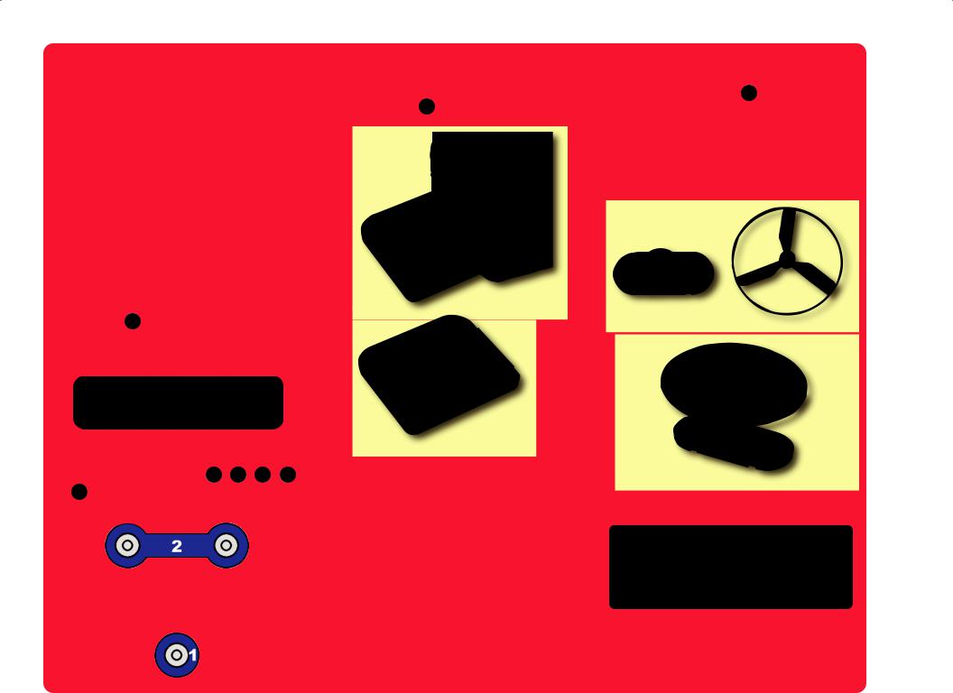
Parts List (Colors and styles may vary) Symbols and Numbers
Important: If any parts are missing or damaged in shipping, DO NOT RETURN TO Target. Call toll-free (800) 533-2441 or e-mail to help@elenco.com. Customer Service ● 150 Carpenter Ave. ● Wheeling, IL 60090 U.S.A.
Qty. |
ID |
Name |
Symbol |
Part # |
|
Qty. |
|
ID |
Name |
Symbol |
Part # |
|
|
|
|
|
|
|
|
|
|
|
|
|
|
r 1 |
|
Base Grid |
|
6SCBG |
|
r 1 |
|
M1 |
Motor |
|
6SCM1 |
|
|
(11.0” x 7.7”) |
|
|
r 1 |
|
Glow Fan |
|
6SCM1FG |
||||
|
|
|
|
|
|
|
|
|
||||
|
|
|
|
|
|
|
|
|
|
|
|
|
r 3 |
1 |
1-Snap Wire |
|
6SC01 |
|
r 1 |
|
Q2 |
NPN Transistor |
|
6SCQ2 |
|
|
|
|
|
|
|
|
|
|
|
|
|
|
r 6 |
2 |
2-Snap Wire |
|
6SC02 |
|
r 1 |
|
R1 |
100Ω Resistor |
|
6SCR1 |
|
|
|
|
|
|
|
|
|
|
|
|
|
|
r 3 |
3 |
3-Snap Wire |
|
6SC03 |
|
r 1 |
|
R2 |
1KΩ Resistor |
|
6SCR2 |
|
|
|
|
|
|
|
|
|
|
|
|
|
|
|
|
|
|
|
|
|
|
|
|
|
|
|
r 1 |
4 |
4-Snap Wire |
|
6SC04 |
|
r 1 |
|
RP |
|
Photoresistor |
|
6SCRP |
|
|
|
|
|
|
|
|
|
|
|
|
|
|
|
|
|
|
|
|
|
|
|
|
|
|
r 1 |
5 |
5-Snap Wire |
|
6SC05 |
|
r 1 |
|
S1 |
Slide Switch |
|
6SCS1 |
|
|
|
|
|
|
|
|
|
|
|
|
|
|
r 1 |
6 |
6-Snap Wire |
|
6SC06 |
|
r 1 |
|
S2 |
Press Switch |
|
6SCS2 |
|
|
|
|
|
|
|
|
|
|
|
|
|
|
r 1 |
B1 |
Battery Holder - uses |
|
6SCB1 |
|
r 1 |
|
SP |
Speaker |
|
6SCSP |
|
Two 1.5V type AA (not incl.) |
|
|
|
|
||||||||
|
|
|
|
|
|
|
|
|
|
|
|
|
|
|
|
|
|
|
|
|
|
|
|
|
|
r 1 |
C5 |
470μF Capacitor |
|
6SCC5 |
|
r 1 |
|
U1 |
Music |
|
6SCU1 |
|
|
|
|
Integrated Circuit |
|
||||||||
|
|
|
|
|
|
|
|
|
|
|
|
|
|
|
|
|
|
|
|
|
|
|
|
|
|
r 1 |
D1 |
Red Light Emitting |
|
6SCD1 |
|
r 1 |
|
U2 |
Alarm |
|
6SCU2 |
|
Diode (LED) |
|
|
|
Integrated Circuit |
|
|||||||
|
|
|
|
|
|
|
|
|
|
|
||
|
|
|
|
|
|
|
|
|
|
|
|
|
r 1 |
L1 |
2.5V Lamp |
|
6SCL1 |
|
r 1 |
|
U3 |
Space War |
|
6SCU3 |
|
|
|
|
Integrated Circuit |
|
||||||||
|
|
|
|
|
|
|
|
|
|
|
|
|
|
|
|
|
|
|
|
|
|
|
|
|
|
-2-
How to Use Circuit Maker Skill Builder 125
Circuit Maker Skill Builder 125 uses building blocks with snaps to build the different electronic circuits in the projects. Each block has a function: there are switch blocks, light blocks, battery blocks, different length wire blocks, etc. These blocks are different colors and have numbers on them so that you can easily identify them. The blocks you will be using are shown as color symbols with level numbers next to them, allowing you to easily snap them together to form a circuit.
For Example:
This is the switch block which is green and has the marking S2 on it. The part symbols in this booklet may not exactly match the appearance of the actual parts, but will clearly identify them.
This is a wire block which is blue and comes in different wire lengths.
This one has the number 2 , 3 , 4 , 5 , or 6 on it depending on the length of the wire connection required.
There is also a 1-snap wire that is used as a spacer or for interconnection between different layers.
You need a power source to build each circuit. This is labeled B1 and requires two (2) 1.5V “AA” batteries (not included).
A  with this kit to help keep the circuit blocks properly spaced. You will see evenly spaced posts that the different blocks snap into. The base has rows labeled A-G and columns labeled 1-10.
Next to each part in every circuit drawing is a small number in black. This tells you which level the component is placed at. Place all parts on level 1 first, then all of the parts on level 2, then all of the parts on level 3, etc.
Usually when the motor M1 is used, the glow fan will be placed on it. On top of the motor shaft is a black plastic piece (the motor top) with three little tabs. Lay the fan on the black piece so the slots in its bottom “fall into place” around the three tabs in the motor top. If not placed properly, the fan will fall off when the motor starts to spin.
Note: While building the projects, be careful not to accidentally make a direct connection across the battery holder (a “short circuit”), as this may damage and/or quickly drain the batteries.
-3-

About Your Circuit Maker Skill Builder 125 Parts
(Part designs are subject to change without notice).
BASE GRID
The base grid is a platform for mounting parts and wires. It functions like the printed circuit boards used in most electronic products, or like how the walls are used for mounting the electrical wiring in your home.
SNAP WIRES
The blue snap wires are wires used to connect components.
They are used to transport and do not affect performance. They come in to allow orderly
arrangement of connections on the base grid.
SLIDE & PRESS SWITCHES
The slide & press switches (S1 & S2) connect (pressed or “ON”) or disconnect (not pressed or “OFF”) the wires in a circuit. When ON they have no effect on circuit performance. Switches turn on electricity just like a faucet turns on water from a pipe.
Slide & Press Switches (S1 & S2)
BATTERY HOLDER
The batteries (B1) produce an electrical voltage using a chemical reaction. This “voltage” can be thought of as electrical pressure, pushing electricity through a circuit just like a pump pushes water through pipes. This voltage is much lower and much safer than that used in your house wiring. Using more batteries increases the “pressure”, therefore, more electricity flows.
Battery Holder (B1)
LAMP
A light bulb, such as in the 2.5V lamp (L1), contains a special thin high-resistance wire. When a lot of electricity flows through, this wire gets so hot it glows bright. Voltages above the bulb’s rating can burn out the wire.
Lamp (L1)
RESISTORS
Resistors “resist” the flow of electricity and are used to control or limit the current in a circuit. Circuit Maker Skill Builder 125 includes 100Ω (R1) and 1KΩ (R2) resistors (“K” symbolizes 1,000, so R2 is really 1,000Ω). Materials like metal have very low resistance (<1Ω), while materials like paper, plastic, and air have nearinfinite resistance. Increasing circuit resistance reduces the flow of electricity.
Resistors (R1 & R2)
The photoresistor (RP) is a light-sensitive resistor, its value changes from nearly infinite in total darkness to about 1,000Ω when a bright light shines on it.
Photoresistor (RP)
CAPACITOR
The 470μF capacitor (C5) can store electrical pressure (voltage) for a period of time. This storage ability allows it to block stable voltage signals and pass changing ones. Capacitors are used for filtering and delay circuits.
Capacitor (C5)
-4-

About Your Circuit Maker Skill Builder 125 Parts
MOTOR
The motor (M1) converts electricity into mechanical motion. An electric
current in the turn the shaft motor blades, and blade if it is on the motor.
Motor (M1)
How does electricity turn the shaft in the motor? The answer is magnetism. Electricity is closely related to magnetism, and an electric current flowing in a wire has a magnetic field similar to that of a very, very tiny magnet. Inside the motor is a coil of wire with many loops wrapped around metal plates. This is called an electromagnet. If a large electric current flows through the loops, it will turn ordinary metal into a magnet. The motor shell also has a magnet on it. When electricity flows through the electromagnet, it repels from the magnet on the motor shell and the shaft spins. If the fan is on the motor shaft, then its blades will create airflow.
Power Contacts
Magnet
Shell
Shaft
Electromagnet
INTEGRATED CIRCUITS (ICs)
Some types of electronic components can be super-miniaturized, allowing many thousands of parts to fit into an area smaller than your fingernail. These “integrated circuits” (ICs) are used in everything from simple electronic toys to the most advanced computers. The music, alarm, and space war ICs (U1, U2, and U3) in Circuit Maker Skill Builder 125 are actually modules containing specialized soundgeneration ICs and other supporting components (resistors, capacitors, and transistors) that are always needed with them. This was done to simplify the connections you need to make to use them. The descriptions for these modules are given here for those interested, see the projects for connection examples:
Music IC:
TRG (+) HLD
(–)OUT
Alarm IC:
IN1 IN2 IN3
(–) OUT
Space War IC:
(+) OUT
IN1 (–) IN2
Connections:
(+) - power from batteries
(–) - power return to batteries OUT - output connection HLD - hold control input TRG - trigger control input
Music for a few seconds on powerup, then hold HLD to (+) power or touch TRG to (+) power to resume music.
Connections:
IN1, IN2, IN3 - control inputs
(–) - power return to batteries OUT - output connection
Connect control inputs to (+) power to make five alarm sounds, see project 22 for configurations.
Connections:
(+) - power from batteries
(–) - power return to batteries OUT - output connection IN1, IN2 - control inputs
Connect each control input to (–) power to sequence through 8 sounds.
-5-

Introduction to Electricity
What is electricity? Nobody really knows. We only know how to produce it, understand its properties, and how to control it. Electricity is the movement of sub-atomic charged particles (called electrons) through a material due to electrical pressure across the material, such as from a battery.
Power sources, such as batteries, push electricity through a circuit, like a pump pushes water through pipes. Wires carry electricity, like pipes carry water. Devices like LEDs, motors, and speakers use the energy in electricity to do things. Switches and transistors control the flow of electricity like valves and faucets control water. Resistors limit the flow of electricity.
The electrical pressure exerted by a battery or other power source is called voltage and is measured in volts (V). Notice the “+” and “–” signs on the battery; these indicate which direction the battery will “pump” the electricity.
The electric current is a measure of how fast electricity is flowing in a wire, just as the water current describes how fast water is flowing in a pipe. It is expressed in amperes (A) or milliamps (mA, 1/1,000 of an ampere).
The “power” of electricity is a measure of how fast energy is moving through a wire. It is a combination of the voltage and current (Power = Voltage x Current). It is expressed in watts (W).
The resistance of a component or circuit represents how much it resists the electrical pressure (voltage) and limits the flow of electric current. The relationship is Voltage = Current x Resistance. When the resistance increases, less current flows. Resistance is measured in ohms (Ω), or kilo ohms (KΩ, 1,000 ohms).
Nearly all of the electricity used in our world is produced at enormous generators driven by steam or water pressure. Wires are used to efficiently transport this energy to homes and businesses where it is used. Motors convert the electricity back into mechanical form to drive machinery and appliances. The most important aspect of electricity in our society is that it allows energy to be easily transported over distances.
Note that “distances” includes not just large distances but also tiny distances. Try to imagine a plumbing structure of the same complexity as the circuitry inside a portable radio - it would have to be large because we can’t make water pipes so small. Electricity allows complex designs to be made very small.
There are two ways of arranging parts in a circuit, in series or in parallel. Here are examples:
Series Circuit
Parallel Circuit
Placing components in series increases the resistance; highest value dominates. Placing components in parallel decreases the resistance; lowest value dominates.
The parts within these series and parallel sub-circuits may be arranged in different ways without changing what the circuit does. Large circuits are made of combinations of smaller series and parallel circuits.
-6-
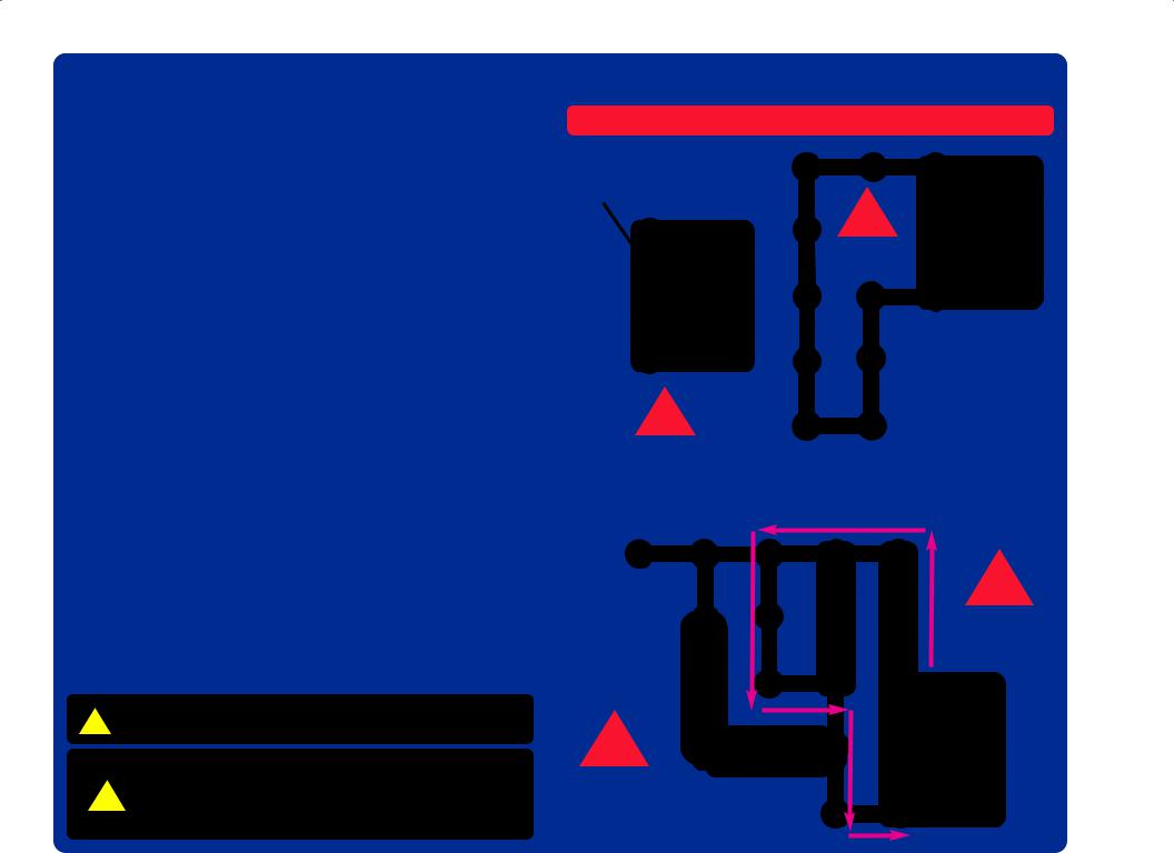
DOs and DON’Ts of Building Circuits
After building the circuits given in this booklet, you may wish to experiment on your own. Use the projects in this booklet as a guide, as many important design concepts are introduced throughout them. Every circuit will include a power source (the batteries), a resistance (which might be a resistor, capacitor, speaker, integrated circuit, etc.), and wiring paths between them and back. You must be careful not to create “short circuits” (very low-resistance paths across the batteries, see examples at right) as this will damage components and/or quickly drain your batteries. Only connect the ICs using configurations given in the projects, incorrectly doing so may damage them. ELENCO® is not responsible for parts damaged due to incorrect wiring.
Here are some important guidelines:
ALWAYS USE EYE PROTECTION WHEN ExPERIMENTING ON YOUR OWN.
ALWAYS include at least one component that will limit the current through a circuit, such as the speaker, lamp, ICs (which must be connected properly), motor, photoresistor, or resistor.
ALWAYS use the LED, NPN transistor, and switches in conjunction with other components that will limit the current through them. Failure to do so will create a short circuit and/or damage those parts.
ALWAYS disconnect your batteries immediately and check your wiring if something appears to be getting hot.
ALWAYS check your wiring before turning on a circuit.
ALWAYS connect capacitors so that the “+” side gets the higher voltage.
ALWAYS connect ICs using configurations given in the projects or as per the connection descriptions for the parts.
NEVER connect to an electrical outlet in your home in any way. NEVER leave a circuit unattended when it is turned on. NEVER touch the motor when it is spinning at high speed.
For all of the projects given in this book, the parts may be arranged in different ways without changing the circuit. For example, the order of parts connected in series or in parallel does not matter — what matters is how combinations of these sub-circuits are arranged together.
WARNING: SHOCK HAZARD - Never connect Circuit Maker
!Skill Builder 125 to the electrical outlets in your home in any way!
Warning to Circuit Maker owners: Do not connect
!additional voltage sources from other sets, or you may damage your parts. Contact ELENCO® if you have questions or need guidance.
Examples of SHORT CIRCUITS - NEVER DO THESE!!!
Placing a 3-snap wire directly across the batteries is a
SHORT CIRCUIT.
!
NEVER
DO!
This is also a
SHORT CIRCUIT.
NEVER ! DO!
When the slide switch (S1) is turned on, this large circuit has a SHORT CIRCUIT path (as shown by the arrows). The short circuit prevents any other portions of the circuit from ever working.
!
NEVER
DO!
!
NEVER
DO!
-7-

Advanced Troubleshooting (Adult supervision recommended)
ELENCO® is not responsible for parts damaged due to incorrect wiring.
If you suspect you have damaged parts, you can follow this procedure to systematically determine which ones need replacing:
1.2.5V lamp (L1), motor (M1), speaker (SP), and battery holder (B1): Place batteries in holder. Place the 2.5V lamp directly across the battery holder, it should light. Do the same with the motor (motor + to battery +), it should spin to the right at high speed. “Tap” the speaker across the battery holder contacts, you should hear static as it touches. If none work then replace your batteries and repeat, if still bad then the battery holder is damaged. If the motor spins but does not balance the fan, check the black plastic piece on the motor shaft; it should have 3 prongs.
2.Snap wires: Use this mini-circuit to test the 5-snap and 6-snap wires. The lamp should light. Then test each of the 1- snap, 2-snap, 3-snap, and 4-snap wires by connecting them
b e t w e e n the ends of the 5-snap and 6-snap.
3.Slide switch (S1) and Press switch (S2): Build Project #1, if the lamp (L1) doesn’t light then the slide switch is bad. Replace the slide switch with the press switch to test it.
4.100Ω resistor (R1), 1KΩ resistor (R2), and LED (D1): Build Project #11 except initially use the speaker (SP) in place of the resistor, the LED should light. Then, replace the speaker with the 100Ω resistor; the LED should still light. Then, replace the 100Ω resistor with the 1KΩ resistor; the LED should light but not as brightly.
5.Alarm IC (U2): Build Project #21, you should hear a siren. Then place a 3- snap wire between grid locations A1 and C1, the sound is different. Then move the 3-snap from A1-C1 to A3-C3 to hear a third sound.
6.Music IC (U1): Build Project #86 but use the press switch (S2) in place of the photoresistor (RP). Turn it on and the LED (D1) flickers for a while and stops, it resumes if you press and hold down the press switch. Then touch a 3- snap wire across base grid points A1 and C1 and the flickering resumes for a while.
7.Space war IC (U3) and photoresistor (RP): Build Project #4, both switches (S1 and S2) should change the sound. Then replace the slide switch (S1) with the photoresistor, waving your hand over it should change the sound.
8.NPN transistor (Q2): Build Project #31. When both switches are on, the lamp lights and motor spins. If one switch is off, nothing happens.
9.470μF capacitor (C5): Build Project #50, then press and release the switch. The LED should go off slowly.
Customer Service
Call toll-free: (800) 533-2441 e-mail: help@elenco.com
-8-

Project Listings
Project # |
Description |
Page # |
|
Project # |
Description |
Page # |
|
Project # |
Description |
Page # |
|
||
|
|
|
|
|
|
|
|
|
|
|
|
|
|
|
1 |
Turn on the Light |
11 |
|
22 |
Laser Blaster |
21 |
|
43 |
Motor Magic |
|
28 |
|
|
2 |
Up, Up, and Away! |
11 |
|
23 |
Mind Reader Game |
22 |
|
44 |
Spin & Shoot |
|
28 |
|
|
3 |
Super Circuit |
12 |
|
24 |
Don’t Make a Sound |
23 |
|
45 |
Spin Out Siren |
|
28 |
|
|
4 |
Space War |
13 |
|
25 |
Discover the Diode |
23 |
|
46 |
Whirl Out Warning |
|
28 |
|
|
5 |
Loud in Light |
13 |
|
26 |
Shine On Siren |
24 |
|
47 |
Turn a Tune |
|
28 |
|
|
6 |
Paper Player |
13 |
|
27 |
Shooting Sounds |
24 |
|
48 |
Wave & Watch |
|
29 |
|
|
7 |
Stick Around Saucer |
14 |
|
28 |
Song & Siren |
24 |
|
49 |
Switching Sounds |
|
29 |
|
|
8 |
Rotate & Roar |
14 |
|
29 |
Ambulance Melody |
24 |
|
50 |
Lingering Light |
|
30 |
|
|
9 |
Spin & Dim |
15 |
|
30 |
Static Song |
24 |
|
51 |
Current Splitter |
|
30 |
|
|
10 |
Balanced Buddies |
15 |
|
31 |
Transistor Control |
25 |
|
52 |
Light Up & Listen |
|
30 |
|
|
11 |
The Diode Dude |
16 |
|
32 |
Slow & Bright |
25 |
|
53 |
Auto-Off Night Light |
|
31 |
|
|
12 |
One Way Works |
16 |
|
33 |
Stop & Shine |
25 |
|
54 |
Auto-Off Day Light |
|
31 |
|
|
13 |
Clippy the Conductor |
17 |
|
34 |
Murky Motor |
25 |
|
55 |
Reflection Detector |
|
32 |
|
|
14 |
Nifty Noises |
17 |
|
35 |
Mixed Up Music |
26 |
|
56 |
Music Reflection Detector |
32 |
|
|
|
15 |
Mumbling Motor |
18 |
|
36 |
Blaster Disaster |
26 |
|
57 |
Laser Flasher |
|
33 |
|
|
16 |
Lift Loss |
18 |
|
37 |
Siren & Song |
26 |
|
58 |
Flash & Flicker |
|
33 |
|
|
17 |
Hi-Low Fan |
19 |
|
38 |
Ambulance Song |
26 |
|
59 |
Spinning Rings |
|
34 |
|
|
18 |
Fuse or Lose |
19 |
|
39 |
Space Battle |
27 |
|
60 |
Strobe the House Lights |
34 |
|
|
|
19 |
Magical Music |
20 |
|
40 |
Bizarre Blinker |
27 |
|
61 |
Race Game |
|
35 |
|
|
20 |
Press & Play |
20 |
|
41 |
Sporadic Sounds |
27 |
|
62 |
Using Parts as Conductors |
35 |
|
|
|
21 |
Simple Siren |
21 |
|
42 |
Blinking Double Flashlight 27 |
|
63 |
Spin Draw |
|
36 |
|
|
|
|
|
|
|
|
|
|
|
|
|
|
|
|
|
|
|
|
|
|
|
|
|
|
|
|
|
|
-9- |
|
|
|
|
|
|
|
|
|
|
|
|
|
Project Listings
|
Project # |
Description |
Page # |
|
Project # |
Description |
Page # |
|
Project # |
Description |
Page # |
|
|
|
|
|
|
|
|
|
|
|
|
|
|
|
|
|
64 |
Singing Motor |
36 |
|
85 |
Electron Warehouse |
44 |
|
106 |
Lagging Light |
|
52 |
|
|
65 |
Visual Volume |
37 |
|
86 |
Light Makes Light |
45 |
|
107 |
Sonic Flasher |
|
53 |
|
|
66 |
Daylight Alarm |
37 |
|
87 |
Go & Glow |
45 |
|
108 |
Stay or Blink |
|
53 |
|
|
67 |
Bang-Bang Bright |
37 |
|
88 |
Spin & Stop |
45 |
|
109 |
Glow & Go |
|
54 |
|
|
68 |
Daylight Danger |
37 |
|
89 |
Flashing Flare |
46 |
|
110 |
Fading Siren |
|
54 |
|
|
69 |
Crooks & Cars |
37 |
|
90 |
Touch & Go |
46 |
|
111 |
Light the Motor |
|
55 |
|
|
70 |
Pop On, Pop Off |
38 |
|
91 |
Two-Tone Twinkler |
46 |
|
112 |
Motor Space Sounds |
|
55 |
|
|
71 |
Little R Rules |
38 |
|
92 |
Fan Flash Energy |
47 |
|
113 |
Twist & Blink |
|
55 |
|
|
72 |
Big R Rules |
38 |
|
93 |
Photo Timer Light |
47 |
|
114 |
Morse Code |
|
56 |
|
|
73 |
Little to Big |
39 |
|
94 |
Room Light to Red Light 47 |
|
115 |
Light to Dark |
|
56 |
|
|
|
74 |
Luminate & Rotate |
39 |
|
95 |
Fun with the Alarm IC |
48 |
|
116 |
Power Shifter |
|
56 |
|
|
75 |
Light to Light |
39 |
|
96 |
Dancing Motor |
48 |
|
117 |
Touch of Light |
|
57 |
|
|
76 |
Switch & Store |
40 |
|
97 |
Musical Light |
48 |
|
118 |
Change & Charge |
|
57 |
|
|
77 |
Crazy Combo |
40 |
|
98 |
Music Alarm Combo |
49 |
|
119 |
Electricity You Can Wear |
58 |
|
|
|
78 |
Alien Alarm |
41 |
|
99 |
Hit the Target |
49 |
|
120 |
Electricity In Your Hair |
58 |
|
|
|
79 |
Same or “NOT” |
41 |
|
100 |
Many Missiles |
49 |
|
121 |
Bending Water |
|
59 |
|
|
80 |
This OR That |
42 |
|
101 |
Sing & Fling |
50 |
|
122 |
Static Tricks |
|
59 |
|
|
81 |
This AND That |
42 |
|
102 |
Power Pitch |
50 |
|
123 |
Sunrise Light |
|
60 |
|
|
82 |
Neither This NOR That 43 |
|
103 |
Long Gone Light |
51 |
|
124 |
Light-controlled Lamp |
|
60 |
|
|
|
83 |
NOT This AND That |
43 |
|
104 |
Slow Siren Changer |
51 |
|
125 |
Motor-controlled Lamp |
60 |
|
|
|
84 |
Two-way Light Switch |
44 |
|
105 |
The Dark Dimmer |
52 |
|
|
|
|
|
|
|
|
|
|
|
|
|
|
|
|
|
|
|
|
|
|
|
|
|
|
|
|
|
|
|
|
|
|
|
|
|
|
|
|
|
|
|
|
|
|
-10- |
|

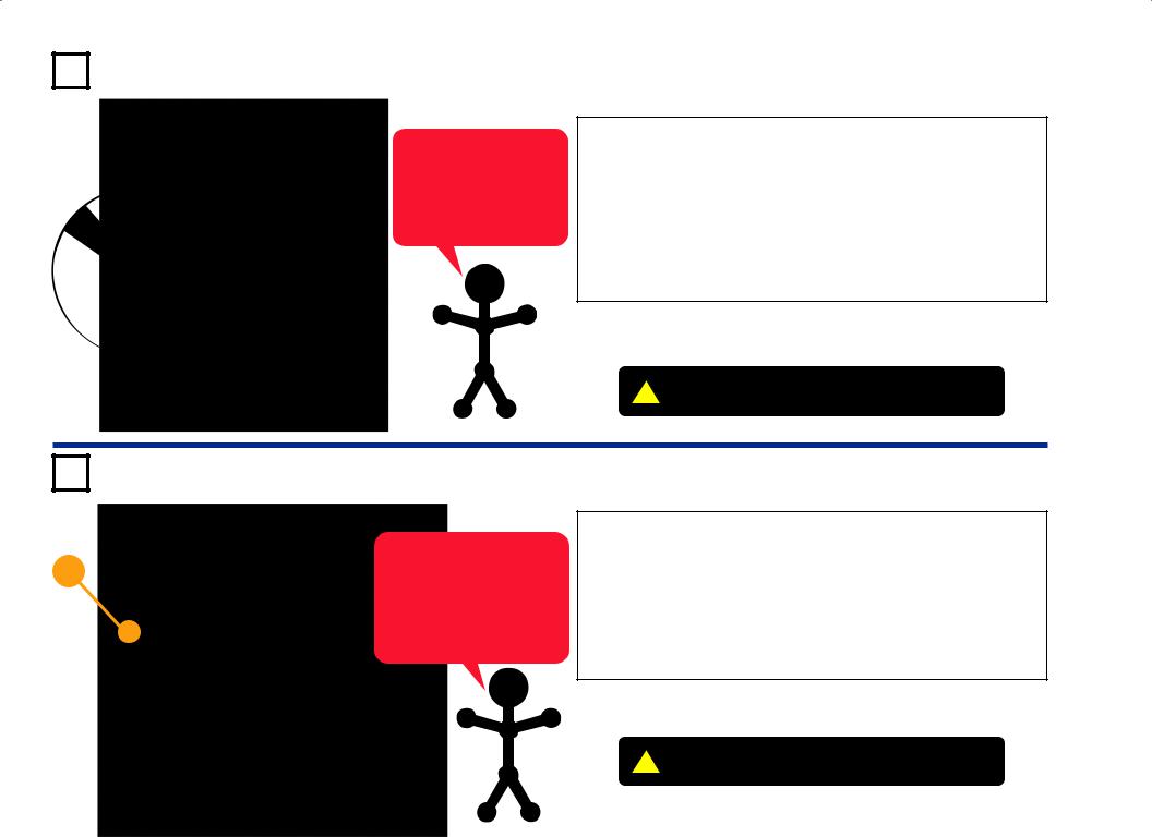
Project #1 |
Turn on the Light |
Snappy says the lamp contains a special thin high-resistance
wire. When a lot of electricity Placement Level Numbers flows through it, it gets so hot it
glows bright.
Circuit Maker Skill Builder 125 uses electronic blocks that snap onto a clear plastic grid to build different circuits. These blocks have different colors and numbers on them so that you can easily identify them.
Build the circuit shown on the left by placing all the parts with a black 1 next to them on the board first. Then, assemble parts marked with a 2. Install two (2) “AA” batteries (not included) into the battery holder (B1) if you have not done so already.
When you turn on the slide switch (S1), electricity flows from the batteries through the lamp (L1) and back to the batteries through the switch. The switch completes the circuit. The lamp gets bright as electricity flows through it.
|
|
|
|
Project #2 |
Up, Up, and Away! |
|||
|
|
|||||||
+ |
|
|
|
|
|
|
|
|
|
|
|
|
|
|
|
Build the circuit shown on the left by placing the parts |
|
|
|
|
|
|
|
|||
|
|
|
|
|
|
The air is being blown down through the blade |
with a black 1 next to them on the base grid first. |
|
|
|
|
|
|
|
and the motor rotation locks the fan on the shaft. |
Then, assemble parts marked with a 2. Place the |
|
|
|
|
|
|
|
|||
|
|
|
|
|
|
When the motor is turned off, the blade unlocks |
glow fan on the motor. New alkaline batteries are |
|
|
|
|
|
|
|
from the shaft and is free to act as a propeller |
recommended for this project. |
|
|
|
|
|
|
|
|||
|
|
|
|
|
|
and fly through the air. If speed of rotation is too |
Turn on the slide switch (S1), wait for the motor to |
|
|
|
|
|
|
|
slow, the fan will remain |
on the motor shaft |
|
|
|
|
|
|
|
reach full speed, then turn off the switch. The glow |
||
|
|
|
|
|
|
because it does not have enough lift to propel it. |
||
|
|
|
|
|
|
fan should rise and float through the air like a flying |
||
|
|
|
|
|
|
|
|
|
|
|
|
|
|
|
|
|
saucer. Be careful not to look directly down on the |
|
|
|
|
|
|
|
|
glow fan when it is spinning. |
|
|
|
|
|
|
|
|
If the fan doesn’t fly off, then turn the switch on and |
|
|
|
|
|
|
|
|
off several times rapidly when it is at full speed. |
|
|
Placement Level Numbers |
|
|
The glow fan will glow in the dark. It will glow best |
|||
|
|
|
|
|
|
|
|
after absorbing sunlight for a while. The glow fan is |
|
|
WARNING: Moving parts. Do not touch the |
|
|||||
! |
|
made of plastic, so be careful not to let it get hot |
||||||
fan or motor during operation. Do not lean |
|
|||||||
|
|
over the motor. |
|
enough to melt. The glow looks best in a dimly lit |
||||
! |
released.WARNING: Fan may not rise until switch is |
|
room. |
|||||
|
|
|||||||
|
|
|||||||
-11-

Project #3 |
Super Circuit |
|
|
Placement Level Numbers |
|
|
|
|
This complex circuit is pictured on the box cover. Use that as a guide to help in building it.
+
!WARNING: Moving parts. Do not touch the fan or motor during operation. Do not lean over the motor.
!WARNING:released. Fan may not rise until switch is
Placement
Level
Numbers
Circuit Maker Skill Builder 125 uses electronic |
Place the glow fan on the motor (M1). |
If the fan doesn’t fly off, then push and release |
||
blocks that snap onto a clear |
plastic grid to |
Turn on the slide switch (S1). You hear music |
the press switch several times rapidly when it is |
|
build different circuits. These |
blocks have |
at full speed. |
||
and alarm sounds, and the red LED (D1) lights. |
||||
different colors and numbers on them so that |
|
|||
The lamp (L1) may light briefly before the red |
If the 470μF capacitor (C5) is discharged when |
|||
you can easily identify them. |
|
|||
|
LED turns on. Cover the photoresistor (RP) to |
you turn on the slide switch, then the lamp will |
||
|
|
|||
Build the circuit shown above by placing all the |
change the sound a little. |
light for a few seconds as the circuit charges up |
||
parts with a black 1 next to them on the board |
Push the press switch (S2) to spin the motor |
C5. L1 will not light again until C5 is |
||
first. Then, assemble parts marked with a 2. |
discharged. To discharge C5, remove it from |
|||
and glow fan. Release the press switch when |
||||
Then, assemble parts marked with a 3. Then, |
the circuit and place it directly on the 4-snap |
|||
the motor is spinning at full speed. The glow fan |
||||
assemble the part marked with a 4 (the alarm |
wire for an instant, then move it back to its |
|||
should float through the air like a flying saucer. |
||||
IC (U2), which should be placed directly over |
normal spot in the circuit. |
|||
Be careful not to look directly down on the glow |
||||
the music IC (U1)). Install two (2) “AA” batteries |
fan when it is spinning. |
|
(not included) into the battery holder (B1). |
||
|
-12-

Project #4 |
|
Space War |
|
|
|
|
|
|
Build the circuit shown on the left, which uses the space war integrated |
|
|
|
circuit. Activate it by flipping the slide switch (S1) or pressing the press |
|
|
|
switch (S2), do both several times and in combination. You will hear an |
|
|
|
exciting range of sounds, as if a space war is raging! |
|
|
|
The space war IC (U3) is a super-miniaturized electronic circuit that |
|
|
|
can play a variety of cool sounds stored in it by using just a few extra |
|
|
|
components. |
|
|
|
In movie studios, technicians are paid to insert these sounds at the |
|
|
|
precise instant a gun is fired. Try making your sound occur at the same |
|
|
|
time an object hits the floor. It is not as easy as it sounds. |
|
|
|
|
|
|
|
|
|
|
|
|
The Space War, Alarm, and Music ICs contain |
|
|
|
specialized ICs combined with other electrical |
|
|
|
components (resistors, capacitors, transistors) |
|
|
|
designed to produce various cool sounds and music. |
|
|
|
|
|
Project #5
Loud in Light 
Use the circuit from Project #4 above, but replace the slide switch (S1) with the photoresistor (RP). The circuit immediately makes noise. Try turning it off. If you experiment, then you can see that the only ways to turn it off are to cover the photoresistor, or to turn off the lights in the room (if the room is dark). Since light is used to turn on the circuit, you might say it is a “light switch”.
The photoresistor contains material that changes its resistance when it is exposed to light; as it gets more light, the resistance of the photoresistor decreases. Parts like this are used in a number of ways that affect our lives. For example, you may have streetlights in your neighborhood that turn on when it starts getting dark and turn off in the morning.
-13-
Project #6
Paper Player
Use the same circuit as for Project #5. Find a piece of white paper that has a lot of large black or dark areas on it, and slowly slide it over the photosensitive resistor. You may need to shine a flashlight over the paper. You should hear the sound pattern constantly changing, as the white and dark areas of the paper control the light to the photosensitive resistance. You can also try the pattern below or something similar to it.

Project #7 |
Stick Around Saucer |
||
+ |
|
||
|
|
|
Build the circuit shown on the left which is the same as the circuit in |
|
|
|
Project #2 but with the motor part reversed. Place the glow fan on the |
|
|
|
motor. |
|
|
|
Turn on the slide switch (S1), wait for the motor to reach full speed, |
|
|
|
|
|
|
|
then turn off the switch. This time, the glow fan does not fly because |
|
|
|
the fan is now rotating in the opposite direction such that the airflow is |
|
|
|
pushing the fan downward. |
|
|
|
|
WARNING: Moving parts. Do not touch the fan or ! motor during operation.
|
Project #8 |
|
Rotate & Roar |
|
|
|
|||
|
|
|
||
|
|
Build the circuit shown on the left, but leave the fan off the motor (M1). |
||
|
|
When you turn on the slide switch (S1), the music may play for a short |
||
|
|
time and then stop. After the music has stopped, spin the motor with |
||
|
|
your fingers. The music should play again for a short time, then stop. |
||
|
|
Now replace the 100Ω resistor (R1) with a 3-snap wire, and notice how |
||
|
|
the sound is affected. |
||
|
|
In this project, you changed the amount of current that goes through |
||
|
|
the speaker (SP) and increased the sound output of the speaker. |
||
|
|
|
|
|
|
|
|
|
|
|
|
|
Resistors are used throughout electronics |
|
|
|
|
to limit the amount of current that flows. |
|
|
|
|
|
|
-14-
Project #9 |
Spin & Dim |
The parts are arranged as a series circuit. You can swap the locations of any of the parts without affecting circuit operation.
Build the circuit shown on the left.
When you turn on the slide switch (S1), the fan will spin and the lamp (L1) should turn on. The fan will take a while to start turning due to inertia. Inertia is the property that tries to keep a body at rest from moving and tries to keep a moving object from stopping.
The lamp helps protect the motor from getting the full voltage when the switch is turned on. Part of the voltage goes across the lamp and the rest goes across the motor. Remove the fan and notice how the lamp gets dimmer when the motor does not have to spin the fan blade.
WARNING: Moving parts. Do not touch the fan or ! motor during operation.
Project #10
The parts are arranged as a + parallel circuit. Parallel circuits are often used in residential homes so that turning on one device doesn’t limit the current to
other devices.
Balanced Buddies
Build the circuit shown on the left.
When you turn on the slide switch (S1), both the fan and the lamp (L1) should turn on. The fan will take a while to start turning due to inertia. In this connection, the lamp does not change the current to the motor (M1). The motor should start a little faster than in Project #9.
Remove the fan and notice how the lamp does not change in brightness as the motor picks up speed. It has its own path to the battery (B1).
WARNING: Moving parts. Do not touch the fan or ! motor during operation.
-15-

Project #11 |
The Diode Dude |
|
|
|
Build the circuit shown on the left. |
|
When you turn on the slide switch (S1), current flows from the batteries |
|
(B1) through the switch, through the 100Ω resistor (R1), through the |
|
LED (D1, light emitting diode) and back to the battery. The turned on |
|
switch completes the circuit. The resistor limits the current and prevents |
|
damage to the LED. NEVER PLACE AN LED DIRECTLY ACROSS |
|
THE BATTERY! If no resistor is in the circuit, the battery may push |
|
enough current through the LED to damage the semiconductor that is |
|
used to produce the light. |
|
|
+ |
|
|
LEDs are used in all types of electronic |
|
|
|
equipment to indicate conditions |
and |
|
|
|
|
pass information to the user of |
that |
|
|
|
equipment. Can you think of something |
|
|
|
|
||
|
|
|
you use everyday that has an LED in it? |
|
|
|
|
|
|
|
|
|
|
|
Project #12
+
One Way Works
Rebuild the circuit used in Project #11 but put the LED in as shown on the left.
This time when you turn on the slide switch (S1), current does not flow from the batteries (B1) through the 100Ω resistor (R1) or through the LED (D1), and hence the LED does not light up. This is because the LED is in backwards. The LED is like a check valve that lets current flow in only one direction (into the + end and out the other end).
An electronic component that needs to be connected in one direction is said to have polarity. Other parts like this will be discussed in future projects. Placing the LED in backwards does not harm it because the voltage is not large enough to break down this electronic component.
-16-

Project #13 |
Clippy the Conductor |
||
|
Rebuild the circuit from Project #11 but leave the slide switch (S1) out |
||
|
as shown on the left. |
||
|
When you place a paper clip across the terminals as shown in the |
||
|
picture on the left, current flows from the batteries (B1) through the |
||
|
100Ω resistor (R1), through the LED (D1), and back to the battery. The |
||
|
paper clip completes the circuit and current flows through the LED. |
||
|
Place your fingers across the terminals and the LED does not light. |
||
|
Your body is too high of a resistance to allow enough current to flow to |
||
|
light the LED. If the voltage, which is electrical pressure, was higher, |
||
|
current could be pushed through your fingers and the LED would light. |
||
|
|
|
|
|
|
This detector can be used to see if a material like plastic is a |
|
|
|
good conductor or a poor conductor. Materials that make the |
|
|
|
LED bright pass electricity easily, and are called conductors. |
|
|
|
Most metals are good conductors, and copper is used in |
|
|
|
most house wiring. Materials that block the flow of electricity |
|
|
|
are called insulators. Plastic, paper and air are insulators. |
|
|
|
|
|
|
|
|
|
|
|
|
|
Project #14 |
|
Nifty Noises |
|
|
Build the circuit shown. Turn it on, press the press switch (S2) several |
||
|
times, and wave your hand over the photoresistor (RP) to hear all the |
||
|
sound combinations. You can make the sound from the alarm IC (U2) |
||
|
louder by replacing the 100Ω resistor (R1) with the 2.5V lamp (L1). |
||
A photoresistor is a light-controlled variable resistor. The resistance of the photoresistor decreases with increasing light intensity.
-17-

|
|
|
Project #15 |
|
Mumbling Motor |
|||
|
|
|||||||
|
|
|
|
|
|
|
||
+ |
|
|
|
Place the fan on the motor (M1). Press the press switch (S2) and listen |
||||
|
|
|
to the motor. Why does the motor make sound? |
|||||
|
|
|
If you replace the motor with the 2.5V lamp (L1), then it will work the |
|||||
|
|
|
|
|
same as the “Hear the Motor” project, but only make noise when the |
|||
|
|
|
|
|
lamp is turned ON or OFF. |
|||
|
|
|
|
|
|
|
||
|
|
|
|
|
|
|
|
|
|
|
|
|
|
A motor uses magnetism to convert electrical |
|
||
|
|
|
|
|
energy into mechanical spinning motion. As the |
|
||
|
|
|
|
|
motor shaft spins around it connects / disconnects |
|
||
|
|
|
|
|
several sets of electrical contacts to give the best |
|
||
|
|
|
|
|
magnetic properties. As these contacts are |
|
||
|
|
|
|
|
switched, an electrical disturbance is created, |
|
||
|
|
|
|
|
which the speaker (SP) converts into sound. |
|
||
|
|
|
|
|
|
|
|
|
|
|
|
|
|
|
|
|
|
|
|
|
|
|
! |
WARNING: Moving parts. Do not touch the |
|
|
|
|
|
|
|
fan or motor during operation. |
|
|
|
|
|
|
|
|
|
|
|
|
|
|
|
|
|
|
|
|
|
|
|
|
|
|
|
|
|
|
|
|
|
Project #16 |
|
Lift Loss |
|||
|
|
|||||||
Build the circuit to the left.
Cover the photoresistor (RP) and turn on the slide switch (S1). The motor (M1) should spin. If not, give it a push to get it started. Now uncover the photoresistor or get a flashlight and shine it on the photoresistor. The motor will slow down as more light reaches the photoresistor, and will stop spinning if enough light reaches the photoresistor. This circuit demonstrates how darkness can be used to control a fan. Try this circuit with and without the fan on the motor.
WARNING: Moving parts. Do not touch the ! fan or motor during operation.
-18-

Project #17
WARNING:
! Moving parts. Do not touch the fan or motor during operation.
Hi-Low Fan
Build the circuit shown on the left.
When you close the slide switch (S1), current flows from the batteries through the slide switch (S1), motor (M1), the lamp (L1), and back to the battery (B1). When the press switch (S2) is closed, the lamp is shorted and motor speed increases.
The principle of removing resistance to increase motor speeds is only one way of changing the speed of the motor. Commercial fans do not use this method because it would produce heat in the resistor and fans are used to cool circuits by moving air over them. Commercial fans change the amount of voltage that is applied to the motor using a transformer or other electronic device.
Project #18 |
Fuse or Lose |
WARNING:
! Moving parts. Do not touch the fan or motor during operation.
Many electronic products in your home have a fuse that will open when too much current is drawn. Can you name some?
Use the circuit built in Project #17.
When you close the slide switch (S1), current flows from the batteries through the slide switch (S1), the lamp (L1), motor (M1), and back to the battery (B1). Pretend the 2-snap wire marked fuse in the drawing on the left is a device that will open the circuit if too much current is taken from the battery. When press switch (S2) is closed, the light is shorted and motor speed increases due to an increase in current to the motor. While still holding press switch (S2) down, remove the 2-snap wire marked fuse and notice how everything stops. Until the fuse is replaced, the open circuit path protects the electronic parts. If fuses did not exist, many parts could get hot and even start fires. Replace the 2-snap wire and the circuit should return to normal.
-19-
 Loading...